EP1520957B1 - Apparatus and method for damping vibrations between a compressor stator vane and a casing of a gas turbine engine - Google Patents
Apparatus and method for damping vibrations between a compressor stator vane and a casing of a gas turbine engine Download PDFInfo
- Publication number
- EP1520957B1 EP1520957B1 EP20030256262 EP03256262A EP1520957B1 EP 1520957 B1 EP1520957 B1 EP 1520957B1 EP 20030256262 EP20030256262 EP 20030256262 EP 03256262 A EP03256262 A EP 03256262A EP 1520957 B1 EP1520957 B1 EP 1520957B1
- Authority
- EP
- European Patent Office
- Prior art keywords
- casing
- stator vane
- damping member
- damping
- gas turbine
- Prior art date
- Legal status (The legal status is an assumption and is not a legal conclusion. Google has not performed a legal analysis and makes no representation as to the accuracy of the status listed.)
- Expired - Lifetime
Links
- 238000013016 damping Methods 0.000 title claims description 46
- 238000000034 method Methods 0.000 title claims description 8
- 239000013536 elastomeric material Substances 0.000 claims description 10
- 230000000717 retained effect Effects 0.000 claims description 5
- 239000012790 adhesive layer Substances 0.000 claims description 3
- YOBAEOGBNPPUQV-UHFFFAOYSA-N iron;trihydrate Chemical compound O.O.O.[Fe].[Fe] YOBAEOGBNPPUQV-UHFFFAOYSA-N 0.000 claims description 2
- 239000004636 vulcanized rubber Substances 0.000 claims description 2
- 238000006073 displacement reaction Methods 0.000 description 2
- 230000000694 effects Effects 0.000 description 2
- 230000001360 synchronised effect Effects 0.000 description 2
- 238000011144 upstream manufacturing Methods 0.000 description 2
- 230000006978 adaptation Effects 0.000 description 1
- 239000000853 adhesive Substances 0.000 description 1
- 230000001070 adhesive effect Effects 0.000 description 1
- 238000011065 in-situ storage Methods 0.000 description 1
- 239000010410 layer Substances 0.000 description 1
- 238000004519 manufacturing process Methods 0.000 description 1
- 239000000463 material Substances 0.000 description 1
- 238000012986 modification Methods 0.000 description 1
- 230000004048 modification Effects 0.000 description 1
- 239000004033 plastic Substances 0.000 description 1
- 229920003023 plastic Polymers 0.000 description 1
Images



Classifications
-
- F—MECHANICAL ENGINEERING; LIGHTING; HEATING; WEAPONS; BLASTING
- F01—MACHINES OR ENGINES IN GENERAL; ENGINE PLANTS IN GENERAL; STEAM ENGINES
- F01D—NON-POSITIVE DISPLACEMENT MACHINES OR ENGINES, e.g. STEAM TURBINES
- F01D25/00—Component parts, details, or accessories, not provided for in, or of interest apart from, other groups
- F01D25/24—Casings; Casing parts, e.g. diaphragms, casing fastenings
- F01D25/246—Fastening of diaphragms or stator-rings
-
- F—MECHANICAL ENGINEERING; LIGHTING; HEATING; WEAPONS; BLASTING
- F01—MACHINES OR ENGINES IN GENERAL; ENGINE PLANTS IN GENERAL; STEAM ENGINES
- F01D—NON-POSITIVE DISPLACEMENT MACHINES OR ENGINES, e.g. STEAM TURBINES
- F01D5/00—Blades; Blade-carrying members; Heating, heat-insulating, cooling or antivibration means on the blades or the members
- F01D5/12—Blades
- F01D5/26—Antivibration means not restricted to blade form or construction or to blade-to-blade connections or to the use of particular materials
-
- F—MECHANICAL ENGINEERING; LIGHTING; HEATING; WEAPONS; BLASTING
- F01—MACHINES OR ENGINES IN GENERAL; ENGINE PLANTS IN GENERAL; STEAM ENGINES
- F01D—NON-POSITIVE DISPLACEMENT MACHINES OR ENGINES, e.g. STEAM TURBINES
- F01D9/00—Stators
- F01D9/02—Nozzles; Nozzle boxes; Stator blades; Guide conduits, e.g. individual nozzles
- F01D9/04—Nozzles; Nozzle boxes; Stator blades; Guide conduits, e.g. individual nozzles forming ring or sector
- F01D9/041—Nozzles; Nozzle boxes; Stator blades; Guide conduits, e.g. individual nozzles forming ring or sector using blades
-
- F—MECHANICAL ENGINEERING; LIGHTING; HEATING; WEAPONS; BLASTING
- F01—MACHINES OR ENGINES IN GENERAL; ENGINE PLANTS IN GENERAL; STEAM ENGINES
- F01D—NON-POSITIVE DISPLACEMENT MACHINES OR ENGINES, e.g. STEAM TURBINES
- F01D9/00—Stators
- F01D9/02—Nozzles; Nozzle boxes; Stator blades; Guide conduits, e.g. individual nozzles
- F01D9/04—Nozzles; Nozzle boxes; Stator blades; Guide conduits, e.g. individual nozzles forming ring or sector
- F01D9/042—Nozzles; Nozzle boxes; Stator blades; Guide conduits, e.g. individual nozzles forming ring or sector fixing blades to stators
Definitions
- the present invention relates generally to stator vanes in compressors of a gas turbine engine and, in particular, to the damping of vibrations transmitted to such stator vanes from the case of the engine.
- stator vanes for the low pressure compressor and/or the high pressure compressor of the engine are generally attached to the engine case. This may be accomplished, for example, by sliding the stator vanes into rails supplied on the inner surface of the case or by capturing a flange between a split-line in the case. In both instances, at least some of the vibration energy of the engine case is transmitted to the stator vanes. Since the individual stator vanes and/or the shroud systems for such stator vanes can vibrate at frequency modes which are substantially synchronous with the case modes, the potential for wear damage and/or high cycle fatigue damage is created.
- US 5, 429,479 describes a stage of vanes where the vanes are embedded in a ring.
- the stage includes a ferrule concentric with the ring, and may include a plurality of springs that bias blocks against the ferrule.
- stator vane assembly it would be desirable for a stator vane assembly to be developed which damps the vibrations from the engine case to the stator vanes of the compressor. It is also desirable for the stator vane assembly to be easily assembled and disassembled to facilitate manufacturing and repair.
- the present invention relates to a stator vane assembly as described in claim 1.
- the present invention relates to a method for damping vibrations as described in claim 7.
- Fig. 1 depicts an exemplary gas turbine engine identified generally by reference numeral 10.
- Gas turbine engine 10 is typically utilized in marine and industrial applications, and includes in serial arrangement a low pressure compressor 12, a high pressure compressor 14, a booster compressor 13, a combustor 16, a high pressure turbine 18 and a low pressure turbine 20. It will be seen that a first shaft 22 connects high pressure turbine 18 and high pressure compressor 14 while a second shaft 24 connects low pressure turbine 20 and low pressure compressor 12.
- a longitudinal axis 25 is provided in Fig. 1 for reference purposes.
- gas turbine engine 10 includes a casing 26 which has a split-line configuration at an axial position adjacent high pressure compressor 14. This is evident from a first circumferential flange 28 and a second circumferential flange 30 being connected in abutting relation with a plurality of circumferentially spaced pins 32 or other similar devices connecting such flanges. It will be noted that a particular stage of stator vanes for high pressure compressor 14 (one stator vane 34 being shown) is positioned immediately downstream of the split-line in casing 26. Due to its proximity to flanges 28 and 30, stator vanes 34 may be more susceptible to the vibrations of casing 26.
- a damping member 36 is preferably positioned within an area 38 defined between an outer portion 40 of each stator vane 34 and casing 26.
- each stator vane 34 is retained within a bushing 44 located in a shroud 45, as is known in the art.
- Outer portion 40 of each stator vane 34 is attached to a platform 47 which is retained by casing 26, where outer platform 47 preferably includes a first or downstream end 46 having a substantially L-shaped design which is sized to fit within a corresponding slot 48 in casing 26.
- a second or upstream end 50 of each outer platform 47 preferably is a flange which is configured and sized so as to be inserted between first and second circumferential flanges 28 and 30, respectively, of casing 26 in abutting relation.
- Each flange 50 also includes at least one opening therethrough so as to permit one or more pins 32 to be inserted therethrough.
- Each outer platform 47 further includes a middle section 52 connecting upstream end 50 and downstream end 46, where middle section 52 extends substantially parallel to casing 26. Because of the respective configurations for each outer platform 47 and casing 26, it will be appreciated that individual open areas 38 are defined therebetween. In order to dampen vibrations experienced by each outer platform 47 (and therefore each stator vane outer portion 40) from casing 26, a damping member 36 is preferably located within each defined open area 38.
- Damping member 36 is preferably constructed of an elastomeric material which preferably is preformed and cured prior to placement within each defined area 38. It will be appreciated that each damping member 36 may be sized to extend within only a portion of each defined area 38 (see Fig. 3) or within substantially all of defined area 38 (see Fig. 4). It will be understood that the elastomeric material will preferably meet certain predefined parameters, including the ability to retain its properties under high temperatures. In particular, the elastomeric material of each damping member 36 will preferably retain its properties in temperatures of at least approximately 300°F, more preferably in temperatures of at least approximately 375°F, and optimally in temperatures of at least approximately 450°F.
- damping member 36 is able to provide similar functionality to stator vanes and their platforms positioned within the temperature environments of low compressor 12 and/or booster compressor 13.
- damping member 36 When positioning damping member 36 within a defined area 38, it is preferred that a layer of adhesive 54 be applied thereto so as to maintain it in position while each stator vane 34 and its platform 47 is connected to casing 26. It will be appreciated that adhesive layer 54 may dissolve or burn off once gas turbine engine 10 is in operation, whereby damping member 36 will be either frictionally engaged in defined area 38 or permitted to float therein.
- damping member 36 in a preformed and cured state is shown to be substantially rectangular in shape, although any shape and size may be utilized provided it performs the desired damping function between casing 26 and stator vanes 34.
- a plurality of grooves 56 is preferably formed in damping member 36 in order to provide better flexibility and assembly (see Fig. 7). Orientation of damping member 36 and grooves 56 within each defined area 38, however, is not deemed to be limiting upon the present invention.
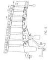
- FIG. 5 and 6 An alternate configuration for the stator vane assembly is depicted in Figs. 5 and 6, where a casing 58 thereof is continuous in an axial direction but has a pair of flanges 60 and 62 which are connected in a clam shell design at opposite radial ends (only one of which is shown).
- This casing configuration further provides a plurality of spaced rail members 64 along an inner surface thereof into which a plurality of stator vanes 66 are inserted and retained prior to assembly of casing 58.
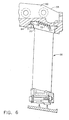
- an open area 68 is accordingly defined between casing 58 and an outer platform 70 for each stator vane 66.
- Each outer platform 70 further includes a pair of end members 71 and 73 which are received within corresponding pockets 75 and 77 of rail member 64.
- a damping member 72 like that discussed above is preferably positioned within each defined area 68 so as to damp the vibrations experienced by outer platforms 70 and stator vanes 66 from casing 58.
- damping member 72 will preferably be of a size and shape so as to fit within open area 68 and perform its intended function.
- elastomeric material may alternatively be squeezed into such areas 68, or "in situ,” where it is able to cure in place and perform as damping member 72.
- damping members 72 are able to be more closely sized to open areas 68. This method may also be utilized with split-line casing 26, as seen in Fig. 4.
- damping members 36 and 72 preferably reduce the vibrations experienced by outer platforms 47 and 70 from casings 26 and 58, respectively, by at least approximately 10%. More preferably, damping members 36 and 72 are able to damp the vibrations from casings 26 and 58 by at least approximately 20% and optimally by at least approximately 30%.
- a method of damping vibrations from casing 26 to stator vanes 34 includes the steps of positioning outer platforms 47 of stator vanes 34 with respect to casing 26 so as to define an open area 38 therebetween, providing damping member 36 made of an elastomeric material within such defined open areas 38 of casing 26, and securing damping members 36 therein. Thereafter, stator vanes 34 are attached to casing 26 so that outer platforms 47 are retained adjacent to damping members 36 and vibrations from casing 26 are dampened. Prior to such steps, damping members 36 are preferably preformed and cured, including grooves 56 formed therein, and adhesive layer 54 applied to a surface thereof. Outer platforms 47 are attached to casing 26 and maintained in position by means of flanges 50 which extend therefrom and are positioned between opposite flanges 28 and 30 of casing 26.
- stator vane assembly and damping member 36 thereof can be accomplished by appropriate modifications by one of ordinary skill in the art without departing from the scope of the invention.
- damping member 36 is illustrated as being used in a stator vane of high pressure compressor 14 for gas turbine engine 10, it may be utilized with any fixed or stator vane of any compressor.
- present invention may be utilized with engine casings have other configurations than that disclosed herein.
Landscapes
- Engineering & Computer Science (AREA)
- Mechanical Engineering (AREA)
- General Engineering & Computer Science (AREA)
- Structures Of Non-Positive Displacement Pumps (AREA)
Description
- The present invention relates generally to stator vanes in compressors of a gas turbine engine and, in particular, to the damping of vibrations transmitted to such stator vanes from the case of the engine.
- It has been found that the case of a gas turbine engine vibrates at various modal frequencies during engine operation. These modal vibrations typically have a wide range of mode shapes, as well as different levels of displacements. It will be appreciated that the fixed stator vanes for the low pressure compressor and/or the high pressure compressor of the engine are generally attached to the engine case. This may be accomplished, for example, by sliding the stator vanes into rails supplied on the inner surface of the case or by capturing a flange between a split-line in the case. In both instances, at least some of the vibration energy of the engine case is transmitted to the stator vanes. Since the individual stator vanes and/or the shroud systems for such stator vanes can vibrate at frequency modes which are substantially synchronous with the case modes, the potential for wear damage and/or high cycle fatigue damage is created.
- In order to prevent such potential damage, gas turbine engines in the prior art have employed a variety of solutions. One solution has been to redesign the engine case to remove the potentially damaging modes of vibration. Another solution has been to redesign the stator vanes or the vane/shroud system to remove the vibration modes which are synchronous with the case vibration modes. Damping material and other vibration damping devices have also been added in the shroud/vane tip area to damp the vibrations experienced by such stator vanes, as evidenced in
U.S. Patent 4,872,812 to Hendley et al. andU.S. Patent 6,343,912 to Manteiga et al. Still another solution has been to add a mechanical damper spring to the base of the stator vane, as seen inU.S. Patent 5,681,142 to Lewis . None of these solutions, however, has been seen to positively effect a change in the vibrations experienced by the stator vanes from the engine casing. -
US 5, 429,479 describes a stage of vanes where the vanes are embedded in a ring. The stage includes a ferrule concentric with the ring, and may include a plurality of springs that bias blocks against the ferrule. - Accordingly, it would be desirable for a stator vane assembly to be developed which damps the vibrations from the engine case to the stator vanes of the compressor. It is also desirable for the stator vane assembly to be easily assembled and disassembled to facilitate manufacturing and repair.
- According to a first aspect, the present invention relates to a stator vane assembly as described in claim 1.
- According to a second aspect, the present invention relates to a method for damping vibrations as described in claim 7.
- Embodiments of the invention will now be described, by way of example, with reference to the accompanying drawings, in which:
- Fig. 1 is a longitudinal cross-sectional view of an exemplary gas turbine engine including a compressor with a stator vane assembly of the present invention;
- Fig. 2 is a partial cross-sectional view of a split-line compressor depicted in Fig. 1, where an embodiment of the stator vane assembly according to the present invention is shown;
- Fig. 3 is an enlarged cross-sectional view of the stator vane assembly depicted in Fig. 2 including a damping member located in a defined area between the stator vane and the engine casing;
- Fig. 4 is an enlarged cross-sectional view of the stator vane assembly depicted in Fig. 2 including an alternative damping member located in a defined area between the stator vane and the engine casing;
- Fig. 5 is a partial cross-sectional view of an engine having an alternative casing configuration, where an embodiment of the stator vane assembly according to the present invention is shown;
- Fig. 6 is an enlarged cross-sectional view of the stator vane assembly depicted in Fig. 5 including a damping member located in a defined area between the stator vane and the engine casing; and,
- Fig. 7 is an enlarged perspective view of the damping member depicted in Figs. 3 and 6.
- Referring now to the drawings in detail, wherein identical numerals indicate the same elements throughout the figures, Fig. 1 depicts an exemplary gas turbine engine identified generally by
reference numeral 10.Gas turbine engine 10 is typically utilized in marine and industrial applications, and includes in serial arrangement alow pressure compressor 12, ahigh pressure compressor 14, abooster compressor 13, acombustor 16, ahigh pressure turbine 18 and alow pressure turbine 20. It will be seen that afirst shaft 22 connectshigh pressure turbine 18 andhigh pressure compressor 14 while asecond shaft 24 connectslow pressure turbine 20 andlow pressure compressor 12. Alongitudinal axis 25 is provided in Fig. 1 for reference purposes. - As seen in Fig. 2,
gas turbine engine 10 includes acasing 26 which has a split-line configuration at an axial position adjacenthigh pressure compressor 14. This is evident from a firstcircumferential flange 28 and a secondcircumferential flange 30 being connected in abutting relation with a plurality of circumferentially spacedpins 32 or other similar devices connecting such flanges. It will be noted that a particular stage of stator vanes for high pressure compressor 14 (onestator vane 34 being shown) is positioned immediately downstream of the split-line incasing 26. Due to its proximity toflanges stator vanes 34 may be more susceptible to the vibrations ofcasing 26. Such casing vibrations, as explained hereinabove, have a wide range of mode shapes with different levels of displacement. In order to lessen the effect such casing vibrations have onstator vanes 34, adamping member 36 is preferably positioned within anarea 38 defined between an outer portion 40 of eachstator vane 34 andcasing 26. - More specifically, it will be seen from Figs. 2 and 3 that a
tang 41 of aninner portion 42 of eachstator vane 34 is retained within a bushing 44 located in ashroud 45, as is known in the art. Outer portion 40 of eachstator vane 34 is attached to a platform 47 which is retained bycasing 26, where outer platform 47 preferably includes a first ordownstream end 46 having a substantially L-shaped design which is sized to fit within acorresponding slot 48 incasing 26. A second orupstream end 50 of each outer platform 47 preferably is a flange which is configured and sized so as to be inserted between first and secondcircumferential flanges casing 26 in abutting relation. Eachflange 50 also includes at least one opening therethrough so as to permit one ormore pins 32 to be inserted therethrough. Each outer platform 47 further includes amiddle section 52 connecting upstreamend 50 anddownstream end 46, wheremiddle section 52 extends substantially parallel tocasing 26. Because of the respective configurations for each outer platform 47 andcasing 26, it will be appreciated that individualopen areas 38 are defined therebetween. In order to dampen vibrations experienced by each outer platform 47 (and therefore each stator vane outer portion 40) fromcasing 26, adamping member 36 is preferably located within each definedopen area 38. -
Damping member 36 is preferably constructed of an elastomeric material which preferably is preformed and cured prior to placement within eachdefined area 38. It will be appreciated that each dampingmember 36 may be sized to extend within only a portion of each defined area 38 (see Fig. 3) or within substantially all of defined area 38 (see Fig. 4). It will be understood that the elastomeric material will preferably meet certain predefined parameters, including the ability to retain its properties under high temperatures. In particular, the elastomeric material of eachdamping member 36 will preferably retain its properties in temperatures of at least approximately 300°F, more preferably in temperatures of at least approximately 375°F, and optimally in temperatures of at least approximately 450°F. One example of such elastomeric material is known as red oxide RTV (Room Temperature Vulcanized Rubber) made by GE Plastics of Pittsfield, Massachusetts. Accordingly, dampingmember 36 is able to provide similar functionality to stator vanes and their platforms positioned within the temperature environments oflow compressor 12 and/orbooster compressor 13. - When positioning
damping member 36 within adefined area 38, it is preferred that a layer ofadhesive 54 be applied thereto so as to maintain it in position while eachstator vane 34 and its platform 47 is connected tocasing 26. It will be appreciated thatadhesive layer 54 may dissolve or burn off oncegas turbine engine 10 is in operation, whereby dampingmember 36 will be either frictionally engaged indefined area 38 or permitted to float therein. As seen in Fig. 7,damping member 36 in a preformed and cured state is shown to be substantially rectangular in shape, although any shape and size may be utilized provided it performs the desired damping function betweencasing 26 andstator vanes 34. Likewise, a plurality ofgrooves 56 is preferably formed in dampingmember 36 in order to provide better flexibility and assembly (see Fig. 7). Orientation of dampingmember 36 andgrooves 56 within eachdefined area 38, however, is not deemed to be limiting upon the present invention. - An alternate configuration for the stator vane assembly is depicted in Figs. 5 and 6, where a
casing 58 thereof is continuous in an axial direction but has a pair offlanges rail members 64 along an inner surface thereof into which a plurality ofstator vanes 66 are inserted and retained prior to assembly ofcasing 58. It will also be appreciated that anopen area 68 is accordingly defined betweencasing 58 and anouter platform 70 for eachstator vane 66. Eachouter platform 70 further includes a pair ofend members corresponding pockets rail member 64. A dampingmember 72 like that discussed above is preferably positioned within eachdefined area 68 so as to damp the vibrations experienced byouter platforms 70 andstator vanes 66 fromcasing 58. Of course, such dampingmember 72 will preferably be of a size and shape so as to fit withinopen area 68 and perform its intended function. - Because access to defined
areas 68 betweencasing 58 and each stator vaneouter portion 70 is not as simple as for the stage ofstator vanes 34 in the split-line casing 26 previously described, it will be appreciated that elastomeric material may alternatively be squeezed intosuch areas 68, or "in situ," where it is able to cure in place and perform asdamping member 72. By providing the elastomeric material in this manner, dampingmembers 72 are able to be more closely sized toopen areas 68. This method may also be utilized with split-line casing 26, as seen in Fig. 4. - It will be appreciated that damping
members outer platforms 47 and 70 fromcasings members casings - It will further be appreciated that a method of damping vibrations from
casing 26 tostator vanes 34 is presented. More specifically, such method includes the steps of positioning outer platforms 47 ofstator vanes 34 with respect to casing 26 so as to define anopen area 38 therebetween, providing dampingmember 36 made of an elastomeric material within such definedopen areas 38 ofcasing 26, and securing dampingmembers 36 therein. Thereafter,stator vanes 34 are attached to casing 26 so that outer platforms 47 are retained adjacent to dampingmembers 36 and vibrations from casing 26 are dampened. Prior to such steps, dampingmembers 36 are preferably preformed and cured, includinggrooves 56 formed therein, andadhesive layer 54 applied to a surface thereof. Outer platforms 47 are attached tocasing 26 and maintained in position by means offlanges 50 which extend therefrom and are positioned betweenopposite flanges casing 26. - An alternative method of damping vibrations from casing 58 to
stator vanes 68 is also demonstrated. This method includes the steps of positioningouter platforms 70 ofstator vanes 66 inrail members 64 incorporated intocasing 58 so as to defineopen areas 68 therebetween and providing dampingmembers 72 made of an elastomeric material within each such definedopen area 68. Further, dampingmembers 72 may be squeezed into each definedarea 68 and permitted to cure. - Having shown and described the preferred embodiment of the present invention, further adaptations of the stator vane assembly and damping
member 36 thereof can be accomplished by appropriate modifications by one of ordinary skill in the art without departing from the scope of the invention. In particular, while dampingmember 36 is illustrated as being used in a stator vane ofhigh pressure compressor 14 forgas turbine engine 10, it may be utilized with any fixed or stator vane of any compressor. Further, the present invention may be utilized with engine casings have other configurations than that disclosed herein.
Claims (7)
- A stator vane assembly for a compressor (14) of a gas turbine engine (10), comprising:(a) a stator vane (34/66) having an inner portion (42) and an outer portion (40);(b) a platform (47/70) attached to said outer portion (40) of said stator vane (34/66);(c) a casing (26/58) for said gas turbine engine (10), wherein said outer platform (47/70) of said stator vane (34/66) is attached to said casing (26/58) in a manner so that an open area (38/68) is defined therebetween; and(d) a member (36/72) positioned within said defined open area (38/68) for damping vibrations transmitted from said casing (26/58) to said outer platform (47/70), characterised in that:said damping member (36/72) is constructed of an elastomeric material.
- The stator vane assembly of claim 1, wherein said damping member (36/72) comprises red oxide room temperature vulcanized rubber (RTV).
- The stator vane assembly of claim 1, wherein said damping member (36/72) is retained within said defined area (38/68) by an adhesive layer (54).
- The stator vane assembly of claim 1, wherein said damping member (36/72) is preformed and cured prior to placement within said defined area (38/68).
- The stator vane assembly of claim 1, wherein said damping member (36/72) includes a plurality of grooves (56) formed in a surface thereof.
- The stator vane assembly of claim 1, wherein said casing (26) has a split-line configuration so that first and second circumferential flanges (28,30) are mated together, said outer platform (47) further comprising a flange (50) located between said first and second circumferential flanges (28,30) of said casing (26).
- A method of damping vibrations from an engine casing (26/58) to a stator vane (34/66) of a compressor (14) connected to said casing (26/58), comprising the following steps:(a) positioning an outer platform (47/70) attached to said stator vane (34/66) with respect to said casing (26/58) so as to define an open area (38/68) therebetween;(b) providing a damping member (36/72) within said defined open area (38/68) of said casing (26/58); and,(c) attaching said outer platform (47/70) to said casing (26/58),
characterized in that:said damping member (36/72) is constructed of an elastomeric material.
Priority Applications (2)
| Application Number | Priority Date | Filing Date | Title |
|---|---|---|---|
| DE2003618852 DE60318852T2 (en) | 2003-10-03 | 2003-10-03 | Apparatus and method for damping vibrations between compressor vanes and the casing of a gas turbine |
| EP20030256262 EP1520957B1 (en) | 2003-10-03 | 2003-10-03 | Apparatus and method for damping vibrations between a compressor stator vane and a casing of a gas turbine engine |
Applications Claiming Priority (1)
| Application Number | Priority Date | Filing Date | Title |
|---|---|---|---|
| EP20030256262 EP1520957B1 (en) | 2003-10-03 | 2003-10-03 | Apparatus and method for damping vibrations between a compressor stator vane and a casing of a gas turbine engine |
Publications (2)
| Publication Number | Publication Date |
|---|---|
| EP1520957A1 EP1520957A1 (en) | 2005-04-06 |
| EP1520957B1 true EP1520957B1 (en) | 2008-01-23 |
Family
ID=34306990
Family Applications (1)
| Application Number | Title | Priority Date | Filing Date |
|---|---|---|---|
| EP20030256262 Expired - Lifetime EP1520957B1 (en) | 2003-10-03 | 2003-10-03 | Apparatus and method for damping vibrations between a compressor stator vane and a casing of a gas turbine engine |
Country Status (2)
| Country | Link |
|---|---|
| EP (1) | EP1520957B1 (en) |
| DE (1) | DE60318852T2 (en) |
Families Citing this family (6)
| Publication number | Priority date | Publication date | Assignee | Title |
|---|---|---|---|---|
| FR2918108B1 (en) * | 2007-06-26 | 2009-10-02 | Snecma Sa | SHOCK ABSORBER DEVICE FOR TURBOMACHINE STATOR |
| US9206700B2 (en) * | 2013-10-25 | 2015-12-08 | Siemens Aktiengesellschaft | Outer vane support ring including a strong back plate in a compressor section of a gas turbine engine |
| US8939717B1 (en) * | 2013-10-25 | 2015-01-27 | Siemens Aktiengesellschaft | Vane outer support ring with no forward hook in a compressor section of a gas turbine engine |
| US9816387B2 (en) | 2014-09-09 | 2017-11-14 | United Technologies Corporation | Attachment faces for clamped turbine stator of a gas turbine engine |
| EP3075961A1 (en) * | 2015-04-02 | 2016-10-05 | Siemens Aktiengesellschaft | Guide vane assembly |
| CN108953130B (en) * | 2018-07-10 | 2019-09-13 | 南京航空航天大学 | A compressor stator blade segment quick release casing device |
Family Cites Families (4)
| Publication number | Priority date | Publication date | Assignee | Title |
|---|---|---|---|---|
| US4897021A (en) * | 1988-06-02 | 1990-01-30 | United Technologies Corporation | Stator vane asssembly for an axial flow rotary machine |
| FR2702242B1 (en) * | 1993-03-03 | 1995-04-07 | Snecma | Free blades stage at one end. |
| US5848874A (en) * | 1997-05-13 | 1998-12-15 | United Technologies Corporation | Gas turbine stator vane assembly |
| US6425736B1 (en) * | 1999-08-09 | 2002-07-30 | United Technologies Corporation | Stator assembly for a rotary machine and method for making the stator assembly |
-
2003
- 2003-10-03 DE DE2003618852 patent/DE60318852T2/en not_active Expired - Lifetime
- 2003-10-03 EP EP20030256262 patent/EP1520957B1/en not_active Expired - Lifetime
Also Published As
| Publication number | Publication date |
|---|---|
| DE60318852T2 (en) | 2009-02-05 |
| EP1520957A1 (en) | 2005-04-06 |
| DE60318852D1 (en) | 2008-03-13 |
Similar Documents
| Publication | Publication Date | Title |
|---|---|---|
| CA2441514C (en) | Apparatus and method for damping vibrations between a compressor stator vane and a casing of a gas turbine engine | |
| JP3701680B2 (en) | Vibration damping shroud for turbomachine blades | |
| US8794908B2 (en) | Stator stage for turbomachine compressor | |
| JP4017216B2 (en) | Turbine blade damper and seal | |
| CA2803342C (en) | Vane assemblies for gas turbine engines | |
| US9410443B2 (en) | Variable vane damping assembly | |
| EP2977558A1 (en) | An annular support, a casing, and vane assembly | |
| US10767690B2 (en) | Bearing housing with damping arrangement | |
| RU2584078C2 (en) | Angular sector of a stator for a turbine engine compressor, a turbine engine stator and a turbine engine including such a sector | |
| JPH06346703A (en) | Damper gear | |
| US8303255B2 (en) | Shaft trim balancing devices, related systems and methods | |
| JP2004124941A5 (en) | ||
| US11359509B1 (en) | Variable guide vane assembly with bushing ring and biasing member | |
| JPH0223204A (en) | Mounting structure of stator blade for axial-flow rotary machine and spring used for said mounting structure | |
| US5215432A (en) | Stator vane damper | |
| EP1520957A1 (en) | Apparatus and method for damping vibrations between a compressor stator vane and a casing of a gas turbine engine | |
| JP2009508031A (en) | Vane assembly with grommets | |
| US8197189B2 (en) | Vibration damping of a static part using a retaining ring | |
| US11028728B2 (en) | Strut dampening assembly and method of making same | |
| US7572098B1 (en) | Vane ring with a damper | |
| JP2024018991A (en) | Vibration damping system for turbine nozzles or turbine blades using stacked plate members | |
| JP2009068338A (en) | Vibration reduction structure of wing | |
| KR101871060B1 (en) | Gas Turbine | |
| US9447693B2 (en) | Compliant assembly | |
| KR101964873B1 (en) | Compressor Having Absorbing Thermal Expansion, And Gas Turbine Having The Same |
Legal Events
| Date | Code | Title | Description |
|---|---|---|---|
| PUAI | Public reference made under article 153(3) epc to a published international application that has entered the european phase |
Free format text: ORIGINAL CODE: 0009012 |
|
| AK | Designated contracting states |
Kind code of ref document: A1 Designated state(s): AT BE BG CH CY CZ DE DK EE ES FI FR GB GR HU IE IT LI LU MC NL PT RO SE SI SK TR |
|
| AX | Request for extension of the european patent |
Extension state: AL LT LV MK |
|
| 17P | Request for examination filed |
Effective date: 20051006 |
|
| AKX | Designation fees paid |
Designated state(s): DE FR GB IT |
|
| GRAP | Despatch of communication of intention to grant a patent |
Free format text: ORIGINAL CODE: EPIDOSNIGR1 |
|
| GRAS | Grant fee paid |
Free format text: ORIGINAL CODE: EPIDOSNIGR3 |
|
| GRAA | (expected) grant |
Free format text: ORIGINAL CODE: 0009210 |
|
| AK | Designated contracting states |
Kind code of ref document: B1 Designated state(s): DE FR GB IT |
|
| REG | Reference to a national code |
Ref country code: GB Ref legal event code: FG4D |
|
| REF | Corresponds to: |
Ref document number: 60318852 Country of ref document: DE Date of ref document: 20080313 Kind code of ref document: P |
|
| ET | Fr: translation filed | ||
| PLBE | No opposition filed within time limit |
Free format text: ORIGINAL CODE: 0009261 |
|
| STAA | Information on the status of an ep patent application or granted ep patent |
Free format text: STATUS: NO OPPOSITION FILED WITHIN TIME LIMIT |
|
| 26N | No opposition filed |
Effective date: 20081024 |
|
| REG | Reference to a national code |
Ref country code: FR Ref legal event code: PLFP Year of fee payment: 13 |
|
| REG | Reference to a national code |
Ref country code: FR Ref legal event code: PLFP Year of fee payment: 14 |
|
| PGFP | Annual fee paid to national office [announced via postgrant information from national office to epo] |
Ref country code: GB Payment date: 20161027 Year of fee payment: 14 Ref country code: FR Payment date: 20161025 Year of fee payment: 14 Ref country code: DE Payment date: 20161027 Year of fee payment: 14 |
|
| PGFP | Annual fee paid to national office [announced via postgrant information from national office to epo] |
Ref country code: IT Payment date: 20161024 Year of fee payment: 14 |
|
| REG | Reference to a national code |
Ref country code: DE Ref legal event code: R119 Ref document number: 60318852 Country of ref document: DE |
|
| GBPC | Gb: european patent ceased through non-payment of renewal fee |
Effective date: 20171003 |
|
| REG | Reference to a national code |
Ref country code: FR Ref legal event code: ST Effective date: 20180629 |
|
| PG25 | Lapsed in a contracting state [announced via postgrant information from national office to epo] |
Ref country code: GB Free format text: LAPSE BECAUSE OF NON-PAYMENT OF DUE FEES Effective date: 20171003 Ref country code: DE Free format text: LAPSE BECAUSE OF NON-PAYMENT OF DUE FEES Effective date: 20180501 |
|
| PG25 | Lapsed in a contracting state [announced via postgrant information from national office to epo] |
Ref country code: FR Free format text: LAPSE BECAUSE OF NON-PAYMENT OF DUE FEES Effective date: 20171031 |
|
| PG25 | Lapsed in a contracting state [announced via postgrant information from national office to epo] |
Ref country code: IT Free format text: LAPSE BECAUSE OF NON-PAYMENT OF DUE FEES Effective date: 20171003 |