EP1520837A1 - Component part of a microfluidic valve - Google Patents
Component part of a microfluidic valve Download PDFInfo
- Publication number
- EP1520837A1 EP1520837A1 EP20040102250 EP04102250A EP1520837A1 EP 1520837 A1 EP1520837 A1 EP 1520837A1 EP 20040102250 EP20040102250 EP 20040102250 EP 04102250 A EP04102250 A EP 04102250A EP 1520837 A1 EP1520837 A1 EP 1520837A1
- Authority
- EP
- European Patent Office
- Prior art keywords
- microfluidic
- microfluidic device
- valve element
- valve
- component part
- Prior art date
- Legal status (The legal status is an assumption and is not a legal conclusion. Google has not performed a legal analysis and makes no representation as to the accuracy of the status listed.)
- Granted
Links
- 230000008878 coupling Effects 0.000 claims description 15
- 238000010168 coupling process Methods 0.000 claims description 15
- 238000005859 coupling reaction Methods 0.000 claims description 15
- 239000007788 liquid Substances 0.000 claims description 12
- 238000001514 detection method Methods 0.000 claims description 4
- CNQCVBJFEGMYDW-UHFFFAOYSA-N lawrencium atom Chemical compound [Lr] CNQCVBJFEGMYDW-UHFFFAOYSA-N 0.000 description 20
- 239000002699 waste material Substances 0.000 description 10
- 238000000034 method Methods 0.000 description 9
- 238000004458 analytical method Methods 0.000 description 4
- 239000012530 fluid Substances 0.000 description 3
- 239000000463 material Substances 0.000 description 3
- 239000007921 spray Substances 0.000 description 3
- 239000004033 plastic Substances 0.000 description 2
- 238000007789 sealing Methods 0.000 description 2
- 239000000126 substance Substances 0.000 description 2
- 238000011144 upstream manufacturing Methods 0.000 description 2
- 239000004642 Polyimide Substances 0.000 description 1
- 238000013459 approach Methods 0.000 description 1
- 230000000712 assembly Effects 0.000 description 1
- 238000000429 assembly Methods 0.000 description 1
- 239000013060 biological fluid Substances 0.000 description 1
- 230000015572 biosynthetic process Effects 0.000 description 1
- 230000001419 dependent effect Effects 0.000 description 1
- 238000013461 design Methods 0.000 description 1
- 238000011161 development Methods 0.000 description 1
- 230000018109 developmental process Effects 0.000 description 1
- 238000005553 drilling Methods 0.000 description 1
- 238000005516 engineering process Methods 0.000 description 1
- 230000004907 flux Effects 0.000 description 1
- 230000003287 optical effect Effects 0.000 description 1
- 229920001721 polyimide Polymers 0.000 description 1
- 238000012545 processing Methods 0.000 description 1
- 238000000926 separation method Methods 0.000 description 1
- 239000000758 substrate Substances 0.000 description 1
- 238000003786 synthesis reaction Methods 0.000 description 1
Images


Classifications
-
- F—MECHANICAL ENGINEERING; LIGHTING; HEATING; WEAPONS; BLASTING
- F16—ENGINEERING ELEMENTS AND UNITS; GENERAL MEASURES FOR PRODUCING AND MAINTAINING EFFECTIVE FUNCTIONING OF MACHINES OR INSTALLATIONS; THERMAL INSULATION IN GENERAL
- F16K—VALVES; TAPS; COCKS; ACTUATING-FLOATS; DEVICES FOR VENTING OR AERATING
- F16K99/00—Subject matter not provided for in other groups of this subclass
- F16K99/0001—Microvalves
-
- F—MECHANICAL ENGINEERING; LIGHTING; HEATING; WEAPONS; BLASTING
- F16—ENGINEERING ELEMENTS AND UNITS; GENERAL MEASURES FOR PRODUCING AND MAINTAINING EFFECTIVE FUNCTIONING OF MACHINES OR INSTALLATIONS; THERMAL INSULATION IN GENERAL
- F16K—VALVES; TAPS; COCKS; ACTUATING-FLOATS; DEVICES FOR VENTING OR AERATING
- F16K99/00—Subject matter not provided for in other groups of this subclass
- F16K99/0001—Microvalves
- F16K99/0003—Constructional types of microvalves; Details of the cutting-off member
- F16K99/0013—Rotary valves
-
- F—MECHANICAL ENGINEERING; LIGHTING; HEATING; WEAPONS; BLASTING
- F16—ENGINEERING ELEMENTS AND UNITS; GENERAL MEASURES FOR PRODUCING AND MAINTAINING EFFECTIVE FUNCTIONING OF MACHINES OR INSTALLATIONS; THERMAL INSULATION IN GENERAL
- F16K—VALVES; TAPS; COCKS; ACTUATING-FLOATS; DEVICES FOR VENTING OR AERATING
- F16K99/00—Subject matter not provided for in other groups of this subclass
- F16K2099/0082—Microvalves adapted for a particular use
- F16K2099/0084—Chemistry or biology, e.g. "lab-on-a-chip" technology
-
- G—PHYSICS
- G01—MEASURING; TESTING
- G01N—INVESTIGATING OR ANALYSING MATERIALS BY DETERMINING THEIR CHEMICAL OR PHYSICAL PROPERTIES
- G01N30/00—Investigating or analysing materials by separation into components using adsorption, absorption or similar phenomena or using ion-exchange, e.g. chromatography or field flow fractionation
- G01N30/02—Column chromatography
- G01N30/04—Preparation or injection of sample to be analysed
- G01N30/16—Injection
- G01N30/20—Injection using a sampling valve
- G01N2030/202—Injection using a sampling valve rotary valves
-
- G—PHYSICS
- G01—MEASURING; TESTING
- G01N—INVESTIGATING OR ANALYSING MATERIALS BY DETERMINING THEIR CHEMICAL OR PHYSICAL PROPERTIES
- G01N35/00—Automatic analysis not limited to methods or materials provided for in any single one of groups G01N1/00 - G01N33/00; Handling materials therefor
- G01N35/10—Devices for transferring samples or any liquids to, in, or from, the analysis apparatus, e.g. suction devices, injection devices
- G01N2035/1027—General features of the devices
- G01N2035/1034—Transferring microquantities of liquid
-
- Y—GENERAL TAGGING OF NEW TECHNOLOGICAL DEVELOPMENTS; GENERAL TAGGING OF CROSS-SECTIONAL TECHNOLOGIES SPANNING OVER SEVERAL SECTIONS OF THE IPC; TECHNICAL SUBJECTS COVERED BY FORMER USPC CROSS-REFERENCE ART COLLECTIONS [XRACs] AND DIGESTS
- Y10—TECHNICAL SUBJECTS COVERED BY FORMER USPC
- Y10T—TECHNICAL SUBJECTS COVERED BY FORMER US CLASSIFICATION
- Y10T137/00—Fluid handling
- Y10T137/8593—Systems
- Y10T137/86493—Multi-way valve unit
- Y10T137/86863—Rotary valve unit
-
- Y—GENERAL TAGGING OF NEW TECHNOLOGICAL DEVELOPMENTS; GENERAL TAGGING OF CROSS-SECTIONAL TECHNOLOGIES SPANNING OVER SEVERAL SECTIONS OF THE IPC; TECHNICAL SUBJECTS COVERED BY FORMER USPC CROSS-REFERENCE ART COLLECTIONS [XRACs] AND DIGESTS
- Y10—TECHNICAL SUBJECTS COVERED BY FORMER USPC
- Y10T—TECHNICAL SUBJECTS COVERED BY FORMER US CLASSIFICATION
- Y10T137/00—Fluid handling
- Y10T137/8593—Systems
- Y10T137/87096—Valves with separate, correlated, actuators
- Y10T137/87121—Coaxial stems
- Y10T137/87129—Rotary
- Y10T137/87145—Concentric, central valve removable
Definitions
- the present invention relates generally to microfluidic laboratory technology for chemical, physical, and/or biological analysis, separation, or synthesis of substances on a substrate with a microfluidic structure. It relates in particular to valves associated with microfluidic assemblies, and more specifically, to component parts of valves adapted to control the flow of liquid samples for analytical purposes.
- microfluidic devices have to fulfill a variety of requirements such as low dead volume and short flow paths with a cross section as constant as possible. This results generally in an improved performance characteristic.
- a sufficient approach in the field ⁇ compared for example to the use of valves with threaded connections - is the use of microfluidic chips coupled to revolving valve elements for flow controlling the microfluidic processes executed within the chip.
- One solution to reduce dead volumes is disclosed for example in the US 2003/0015682 A1. Due to enormous amounts of samples and components to be analyzed, efforts in the field are made as well to reduce analyzing time.
- a component part of a microfluidic valve adapted to be coupled with a microfluidic device.
- the component part comprises a first revolving valve element with a first interface with the microfluidic device.
- the microfluidic device comprises at least one port.
- the component part is characterized by a second valve element with a second interface with the microfluidic device.
- the second revolving valve element is located within a through hole or recess of the first revolving valve element.
- a through hole is understood in this application as any kind of hole, bore, or opening having any shape. Embodiments may include one or more of the following.
- the port of the microfluidic device can be flow controlled by the interface.
- Liquid flowing through the port can be sealed or coupled to the flow path of the microfluidic device.
- Each valve element can flow-control the port or further ports of the microfluidic device.
- the valve elements are coaxially rotatable. Ports to be flow-controlled by the valve elements can be arranged in two concentric circles on the microfluidic device. An outer circle can be assigned to the first revolving valve element and an inner one to the second revolving valve element.
- Embodiments may also include one or more of the following.
- the through hole is a cylindrical hole.
- the second revolving valve element has at least partly a cylindrical shape and is located within the first revolving valve element with a clearance fit. The clearance fit is easy to produce and behaves like a bearing for the second revolving valve element.
- the second revolving valve element can therefore be shaped like a shaft.
- Preferred the first revolving valve element has at least partly the shape of a hollow cylinder. Hollow cylinders can be produced easily, for example by turning and drilling.
- Embodiments may also include one or more of the following.
- At least one of the valve elements has a coupling, in particular a step, for coupling with an actuator.
- the valve elements can be easily adjusted.
- Preferred the valve elements are adapted to be actuated by rotating them coaxially, separately, or concurrently in any direction of rotating.
- Advantageously a variety of settings of the valve elements can be achieved.
- the second revolving valve element comprises a center blind hole or a through bore.
- the through bore can be connected to another flow path.
- the interfaces are adapted to interact with the port of the microfluidic device to flow-control and/or seal them.
- the interfaces of the valve elements comprise at least one fluid-conducting feature, for example a groove.
- the groove is preferred scratched, grinded, formed, or such in a substantially planar contact surface of the valve elements.
- the planar surface can be put against a surface of the microfluidic device for sealing the port.
- the invention further relates to an assembly for handling liquid with a multi-route switching valve.
- the assembly comprises a microfluidic device, in particular a microfluidic chip.
- the valve can interact with the microfluidic device for flow-controlling the port.
- the assembly is characterized in that the valve is realized by the microfluidic device and a component part in any design as described above.
- Embodiments may include one or more of the following.
- the port is coupled to a flow path of the microfluidic device.
- the component part comprises at least two valve elements.
- the planar surface of the valve elements can be put against a surface of the microfluidic device close to the port for flow-controlling the port.
- a plurality of ports can be sealed, switched, or coupled by the valve to realize complex microfluidic processes to be executed with the device.
- Embodiments may also include one or more of the following.
- the interfaces with the fluid-conducting features, the valve elements, and the microfluidic device realize the valve.
- the microfluidic device can be a disposable part, for example a cheaply producible microfluidic plastic chip.
- the valve elements that have to be highly dimensionally accurate, can be put or rather pressed against many different chips or more precise against a surface of the chips for coupling close to the ports of the chips.
- Preferred the microfluidic device is adapted for analyzing and/or separating components of a liquid, in particular by a detection area within or nearby the microfluidic flow path. This process can be easily controlled by the valve of the assembly.
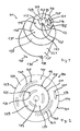
- Fig. 1 shows a component part 101 of a microfluidic valve with a first revolving valve element 103 and a second revolving valve element 105.
- the valve elements 103 and 105 have a first interface 107 and a second interface 109 that can be coupled to a microfluidic device (not shown).
- the second revolving valve element 105 is located in this embodiment within a cylindrical hole 111 of the first revolving valve element 103.
- the first revolving valve element 103 can comprise any kind of through hole instead of the cylindrical hole 111.
- the through hole and accordingly the second revolving valve element 105 are conically formed.
- the second revolving valve element 105 can have at least partly the shape of a cone, fitting into the conical through hole of the first revolving valve element 103.
- the second revolving valve element 105 has in this embodiment at least partly a cylindrical shape or rather the shape of a shaft.
- the second revolving valve element 105 and the cylindrical hole 111 of the first revolving valve element 103 build a clearance fit 113.
- the clearance fit 113 has the function of a bearing for the second revolving valve element 105.
- the Interfaces 107 and 109 each comprise a substantially planar contact surface 115 and 117.
- the surface 115 of the first revolving valve element 103 comprises a first fluid conducting feature 119 comprising a first groove 121.
- the surface 117 of the second revolving valve element 105 comprises three further fluid conducting features 123 comprising three further grooves 125.
- the groves 121 and 125 are arranged along sectors of around 60° of concentric circles around the axis of rotation of the first revolving valve element 103 and the second revolving valve element 105.
- the elements 103 and 105 are coaxially rotatable by their center axis.
- the surfaces 115 and 117 each are rectangular to the center axis of the elements 103 and 105.
- the first revolving valve element 103 comprises a body 127 with a greater diameter than the diameter of the first interface 107.
- the first revolving valve element 103 has partly the shape of a hollow cylinder 129 with a cylindrical surface 131.
- the diameter of the cylinder 129 widens at a circumferential step 133 of the first revolving valve element 103.
- the body also has the shape of a hollow cylinder with a cylindrical surface 135, but with a greater wall thickness than the hollow cylinder 129.
- the body 127 of the first revolving valve element 103 makes handling and coupling of the component part 101 easier.
- the body 127 of the first revolving valve element 103 and the second revolving valve element 105 comprise a coupling 137 for coupling with an actuator (not shown).
- the coupling comprises in this embodiment a step 139 of the body 127 of the first revolving valve element 103.
- the step 139 can be engaged with an according lug or projection of the actuator.
- the actuator can apply a torque for rotating to the first revolving valve element 103 in at least one rotating direction - symbolized with an arrow 141.
- the first revolving valve element 103 can comprise a second step for rotating the first revolving valve element 103 in the opposite direction of rotation.
- the second revolving valve element 105 can comprise in embodiments according features to be rotated.
- the coupling 137 can comprise any other features for coupling like groves, flutes, and threads or alike.
- the elements 103 and 105 can be rotated synchronously or asynchronously in only one or any direction of rotation.
- the second revolving valve element 105 can be adjusted in rotations by 60° in just one direction from a first setting to a second setting and back, because the grooves each are arranged rotationally symmetric in the surface 117 of the second revolving valve element 105. Consequently, the same setting results from a rotation of 120° of the grooves.
- Fig. 2 shows a front view of another component part 143 similar to the component part 101 of a microfluidic valve. Therefore, only the differences are described.
- the second revolving valve element 105 of the component part 143 comprises two additionally fluid conducting features 145 with grooves 147.
- the grooves 147 are circular.
- the groves 147 and 121 are inserted 180° rotationally symmetric and in circles with different diameters in the surface 115 of the second revolving valve element 105. Consequently, the same setting results from a rotation of 180° of the grooves.
- Ports of the microfluidic device can be arranged in three different circles. Ports arranged in a first circle can be flow-controlled by the grooves 125 of the second valve element 105, in a second circle by the grooves 147 of the first valve element 103, and in a third circle by the grooves 121 of the first valve element 103. By this, highly integrated and complex fluidic circuits with many interconnections to be controlled can be realized.
- the second revolving valve element 105 of the component part 143 comprises a center blind hole 151 to avoid wearing and undefined condition of the surface 117 and any leaks.
- the lengths of the grooves 125 of the second revolving valve element 105 are equal to the lengths of the grooves 121 of the first revolving valve element 103. Because of the different diameters of the valve elements 103 and 105, they have to be rotated in different angels for adjusting the grooves 121 and 125. Ports according to the groove 121 of the first revolving valve element 103 can be arranged relatively close to each other by this. Advantageously this results in short flow paths and low dead volumes.
- the rotational angel to adjust the grooves 121 and 125 of the valve elements 103 and 105 can be each adapted to the length of the grooves 121 and 125 separately by rotating the valve elements 103 and 105 independently.
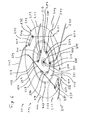
- Fig. 3 shows a schematic layout of a microfluidic chip 201 showing microfluidic structures, in particular flow paths and analytical columns, being part of a microfluidic assembly 202 for handling liquid with a multi-route switching valve 204.
- the microfluidic chip 201 can comprise or consist of any material, preferred a flexible material, for example plastic or rather any polymeric material. In another preferred embodiment, the microfluidic chip 201 comprises polyimide.
- Fig. 4A and 4B show detailed views of the microfluidic chip 201 as shown in Fig. 3 together with a component part 203 of the microfluidic valve 204 in two different settings.
- the component part 203 comprises a first valve element 207 and a second valve element 205 - each symbolized by dotted lines ⁇ realizing the multi-route switching valve 204 together with the microfluidic chip 201.
- the elements 205 and 207 are adapted for sealing and/or coupling one or more ports - 12 ports 209 to 231 in this embodiment- of the microfluidic chip 201.
- the figures 3, 4A, and 4B show how highly integrated and parallelized processes that can be executed with the assembly 202 for handling liquid with a multi-route switching valve 204.
- Fig. 5A, 5B, and 5C show different cross-sectional views of the device of Figure 3, taken along the lines A - A, B - B and C - C of Figure 3.
- Fig. 6 shows a three-dimensional schematic view of the component part 203 and with the partially shown three-dimensional layout of the microfluidic chip 201 of the figures 3 to 5.
- the elements 205 and 207 have essentially a cylindrical shape, wherein the first valve element 207 has essentially the shape of a hollow cylinder.
- the second valve element 205 is arranged within the opening of the hollow cylinder of the first valve element 207.
- the concentric elements 205 and 207 are adapted to be rotated separately.
- Each of the elements 205 and 207 comprise an interface with a substantially planar surface 232 with at least one fluid-conducting feature, for example, a groove 233 to 241, to flow-control the ports of the microfluidic chip 201.
- Each interface comprises at least one of the groves 233 to 241 - symbolized with dotted lines in the figures 4A and 4B - to couple and/or to control the flux within the ports 209 to 231 of the microfluidic chip 201.
- the microfluidic chip 201 comprises a surface 242 for coupling with the substantially planar contact surfaces 232 of the interfaces of the valve elements close to the port.
- the elements 205 and 207 can be adjusted by rotating them along their cylindrical middle axis.
- the ports 209 to 231 of the microfluidic chip 201 are arranged on circles or rather on the corner points of an equilateral hexagon - ports 213 to 223 - in this embodiment.
- the microfluidic chip 201 comprises a first combination column 243, a second combination column 245, a spray tip 247 and a flow path 249 coupled to the spray tip 247.
- the flow path 249 comprises a forking 251 coupled to a first analysis port 209 and a second analysis port 211.
- the microfluidic chip 201 comprises three layers, a top layer 253, a middle layer 255, and a bottom layer 257.
- the top layer 253 comprises the combination columns 243 and 245.
- the middle layer 255 comprises the flow path 249 as shown in Figure 5B with the forking 251.
- the bottom layer 257 comprises two flow paths 259 and 261 each coupled to an inlet port 213 or rather 215 and an outlet port 217 or rather 219 of the microfluidic chip 201.
- the inlet ports 213 and 215 are double ports each with two openings on the top side and on the bottom side of the microfluidic chip 201. The two openings are separated by the middle layer 255 of the microfluidic chip 201.
- the outlet ports 217 and 219 are located on the top side of the microfluidic chip 201 an can be realized by holes in the middle layer 255 and the top layer 253 of the microfluidic chip 201.
- the inlet ports 213 and 215 can be coupled at the bottom side of the microfluidic chip 201 to two nano-pumps. Inflowing liquid can flow from the bottom side of the microfluidic chip 201 through the flow paths 259 and 261 in the bottom layer of the microfluidic chip 201, to the outlet ports 217 and 219 on the top side of the microfluidic chip 201.
- the flow path 249 is implemented in the middle layer 255.
- the first combination column 243 and the second combination column 245 are implemented in the top layer 253.
- the first combination column 243 and the second combination column 245 cross the forking 251 of the flow path 249. This is possible because the middle layer 255 separates these flow paths.
- the first combination column 243 can be coupled upstream to a microfluidic sample-feeding device (not shown) via a sample inlet port 221 via a groove 233 of the second valve element 205, and via the inlet port 213.
- the sample inlet port 221 can be realized by a hole through all layers 253, 255, and 257 of the microfluidic chip 201.
- the sample inlet port 221 can be coupled at the bottom side of the microfluidic chip 201 to the sample-feeding device.
- the first combination column 243 can be coupled downstream to a waste container via a first column port 225, via a second outer groove 235 of the first valve element 207, via a first waste port 229, via a waste flow path 263, and via a waste outlet port 223 at the bottom side of the microfluidic chip 201.
- the waste flow path 263 is implemented in the middle layer 255 of the microfluidic chip 201 and is coupled to the waste outlet port 223.
- the waste container can be coupled at the bottom side of the microfluidic chip 201 or rather to the waste outlet port 223.
- the waste outlet port 223 can be realized by a hole through all layers 253, 255, and 257 of the microfluidic chip 201.
- the flow path described above can be used for injecting a sample to the first combination column 243.
- the second combination column 245 can be coupled upstream for example to a nano-pump via a the second inlet port 215 at the top side of the microfluidic chip 201, via a inner grove 239 of the second valve element 205, via the second outlet port 219, via the flow path 261, and via the second inlet port 215 at the bottom side of the microfluidic chip 201.
- the second combination column 245 can be coupled downstream to a laboratory apparatus (not shown) via a second column port 227, via a second outer groove 237 of the first valve element 207, via a second analysis port 211, via the forking 251 of the flow path 249, via the flow path 249, and via the spray tip 247 of the microfluidic chip 201.
- the flow path described above can be used for analyzing a liquid with a combination column as known in the art.
- the microfluidic chip 201 is adapted to execute two processes in parallel.
- the elements 205 and 207 can be adapted to interact with more or less than six ports.
- the layout of the microfluidic chip 201 can for example be transformed to interact with one six-port and one ten-port multi-route switching valve.
- the microfluidic chip 201 can have a detection area 269, for example an optical detection area, to analyze the liquid within the microfluidic chip 201, for example within the flow path 249.
- a detection area 269 for example an optical detection area
- the second valve element comprises, instead of or additionally to the center blind hole 151, a through bore 271 - illustrated with dotted lines ⁇ and the microfluidic chip 201 comprises a center port 273.
- the port 273 can be fed alternatively or synchronously with liquid through the through bore 271 or can be connected to a waste container for realizing other microfluidic circuits.
- the microfluidic chip 201 comprises at least one hole 275 to align the microfluidic chip 201, in particular the ports of the microfluidic chip 201, relatively to the component part 203.
- the microfluidic chip 201 comprises two holes 275.
- the microfluidic chip 201 can be fitted to two pins (not shown) by the holes 275 to align the microfluidic chip 201.
- the component part 203 may be free to rotate but is positioned in a constant position to the pins.
- the second revolving valve element is located within and/or adjacent to a recess - instead of the through hole as described above - of the first revolving valve element.
- the first revolving valve element may have for example the shape of a half-hollow cylinder. In this example, the half-round inside of the half-hollow cylinder realizes the recess.
- the recess may have any other shape.
- the component part 203 comprises more than two valve elements free to rotate to each other.
- the microfluidic assembly can comprise more than one valve comprising a component part 203.
Landscapes
- Engineering & Computer Science (AREA)
- General Engineering & Computer Science (AREA)
- Chemical & Material Sciences (AREA)
- Dispersion Chemistry (AREA)
- Mechanical Engineering (AREA)
- Automatic Analysis And Handling Materials Therefor (AREA)
- Micromachines (AREA)
- Multiple-Way Valves (AREA)
- Temperature-Responsive Valves (AREA)
Abstract
Description
- The present invention relates generally to microfluidic laboratory technology for chemical, physical, and/or biological analysis, separation, or synthesis of substances on a substrate with a microfluidic structure. It relates in particular to valves associated with microfluidic assemblies, and more specifically, to component parts of valves adapted to control the flow of liquid samples for analytical purposes.
- There is a growing demand for biological fluid processing systems that have generated a need for small fluidic valves. Such miniaturized microfluidic devices has to fulfill a variety of requirements such as low dead volume and short flow paths with a cross section as constant as possible. This results generally in an improved performance characteristic. A sufficient approach in the field ― compared for example to the use of valves with threaded connections - is the use of microfluidic chips coupled to revolving valve elements for flow controlling the microfluidic processes executed within the chip. One solution to reduce dead volumes is disclosed for example in the US 2003/0015682 A1. Due to enormous amounts of samples and components to be analyzed, efforts in the field are made as well to reduce analyzing time. These efforts have led to parallelized and more time efficient processesas shown for example in the
EP 1 162 464 A1 or in the WO 01/84143 A1, but also to higher complexity of systems and executed processes, and consequently to an increased expenditure for controlling. In particular, coupling and flow controlling is an important matter of the latest developments in the technical field of microfluidic devices as shown for example in the EP 0 310 4413.4 (not published yet). Increasing the complexity of the processes executed by the microfluidic devices generally results disadvantageously in a higher amount of interconnections to be realized, switched, and/or flow controlled. - It is an object of the invention to provide an improved controlling, in particular flow controlling, of microfluidic devices. The object is solved by the independent claims. Preferred embodiments are shown by the dependent claims.
- According to the present invention, the objects indicated are achieved by a component part of a microfluidic valve adapted to be coupled with a microfluidic device. The component part comprises a first revolving valve element with a first interface with the microfluidic device. The microfluidic device comprises at least one port. The component part is characterized by a second valve element with a second interface with the microfluidic device. The second revolving valve element is located within a through hole or recess of the first revolving valve element. A through hole is understood in this application as any kind of hole, bore, or opening having any shape. Embodiments may include one or more of the following. The port of the microfluidic device can be flow controlled by the interface. Liquid flowing through the port can be sealed or coupled to the flow path of the microfluidic device. Each valve element can flow-control the port or further ports of the microfluidic device. To couple, for example a first port flow-controlled by the first revolving valve element with a second port flow-controlled by the second revolving valve element, only a distance shorter than the diameter of the first revolving valve element has to be bridged by a flow path. This guarantees microfluidic devices with higher integrated microfluidic structures with minimal dead volume and consequently improved performance characteristics.
- According to embodiments of the present invention, the valve elements are coaxially rotatable. Ports to be flow-controlled by the valve elements can be arranged in two concentric circles on the microfluidic device. An outer circle can be assigned to the first revolving valve element and an inner one to the second revolving valve element.
- Embodiments may also include one or more of the following. Preferred the through hole is a cylindrical hole. The second revolving valve element has at least partly a cylindrical shape and is located within the first revolving valve element with a clearance fit. The clearance fit is easy to produce and behaves like a bearing for the second revolving valve element. The second revolving valve element can therefore be shaped like a shaft. Preferred the first revolving valve element has at least partly the shape of a hollow cylinder. Hollow cylinders can be produced easily, for example by turning and drilling.
- Embodiments may also include one or more of the following. At least one of the valve elements has a coupling, in particular a step, for coupling with an actuator. With this, the valve elements can be easily adjusted. Preferred the valve elements are adapted to be actuated by rotating them coaxially, separately, or concurrently in any direction of rotating. Advantageously a variety of settings of the valve elements can be achieved. The second revolving valve element comprises a center blind hole or a through bore. The through bore can be connected to another flow path. The interfaces are adapted to interact with the port of the microfluidic device to flow-control and/or seal them. For this purpose, the interfaces of the valve elements comprise at least one fluid-conducting feature, for example a groove. The groove is preferred scratched, grinded, formed, or such in a substantially planar contact surface of the valve elements. The planar surface can be put against a surface of the microfluidic device for sealing the port.
- The invention further relates to an assembly for handling liquid with a multi-route switching valve. The assembly comprises a microfluidic device, in particular a microfluidic chip. The valve can interact with the microfluidic device for flow-controlling the port. The assembly is characterized in that the valve is realized by the microfluidic device and a component part in any design as described above. Embodiments may include one or more of the following. The port is coupled to a flow path of the microfluidic device. The component part comprises at least two valve elements. The planar surface of the valve elements can be put against a surface of the microfluidic device close to the port for flow-controlling the port. A plurality of ports can be sealed, switched, or coupled by the valve to realize complex microfluidic processes to be executed with the device.
- Embodiments may also include one or more of the following. The interfaces with the fluid-conducting features, the valve elements, and the microfluidic device realize the valve. The microfluidic device can be a disposable part, for example a cheaply producible microfluidic plastic chip. The valve elements that have to be highly dimensionally accurate, can be put or rather pressed against many different chips or more precise against a surface of the chips for coupling close to the ports of the chips. Preferred the microfluidic device is adapted for analyzing and/or separating components of a liquid, in particular by a detection area within or nearby the microfluidic flow path. This process can be easily controlled by the valve of the assembly.
- Other objects and many of the attendant advantages of embodiments of the present invention will be readily appreciated and become better understood by reference to the following more detailed description of preferred embodiments in connection with the accompanied drawings. Features that are substantially or functionally equal or similar will be referred to with the same reference signs.
- Fig. 1 shows a three-dimensional view of a component part of a microfluidic valve;
- Fig. 2 shows a front view of an interface of another component part of a microfluidic valve;
- Fig. 3 shows a schematic layout of a microfluidic chip with microfluidic structures, in particular flow paths and combination columns;
- Fig. 4A and 4B show detailed views of the microfluidic chip as shown in Fig. 3 together with a sketched component part of a microfluidic valve in two different settings;
- Fig. 5A, 5B, and 5C show different cross-sectional views of the device of Figure 3, taken along the lines A - A, B - B and C - C of Figure 3; and
- Fig. 6 shows a three-dimensional schematic view of another component part with a partially shown three-dimensional layout of the microfluidic chip of figure 3.
-
- Fig. 1 shows a
component part 101 of a microfluidic valve with a first revolvingvalve element 103 and a second revolving valve element 105. Thevalve elements 103 and 105 have afirst interface 107 and asecond interface 109 that can be coupled to a microfluidic device (not shown). - The second revolving valve element 105 is located in this embodiment within a
cylindrical hole 111 of the first revolvingvalve element 103. Preferred the first revolvingvalve element 103 can comprise any kind of through hole instead of thecylindrical hole 111. In another preferred embodiment the through hole and accordingly the second revolving valve element 105 are conically formed. - Consequently, the second revolving valve element 105 can have at least partly the shape of a cone, fitting into the conical through hole of the first revolving
valve element 103. - The second revolving valve element 105 has in this embodiment at least partly a cylindrical shape or rather the shape of a shaft. The second revolving valve element 105 and the
cylindrical hole 111 of the first revolvingvalve element 103 build aclearance fit 113. The clearance fit 113 has the function of a bearing for the second revolving valve element 105. - The
Interfaces planar contact surface 115 and 117. Thesurface 115 of the first revolvingvalve element 103 comprises a first fluid conducting feature 119 comprising afirst groove 121. The surface 117 of the second revolving valve element 105 comprises three further fluid conducting features 123 comprising threefurther grooves 125. Thegroves valve element 103 and the second revolving valve element 105. Theelements 103 and 105 are coaxially rotatable by their center axis. Thesurfaces 115 and 117 each are rectangular to the center axis of theelements 103 and 105. - The first revolving
valve element 103 comprises abody 127 with a greater diameter than the diameter of thefirst interface 107. The first revolvingvalve element 103 has partly the shape of ahollow cylinder 129 with acylindrical surface 131. The diameter of thecylinder 129 widens at acircumferential step 133 of the first revolvingvalve element 103. The body also has the shape of a hollow cylinder with acylindrical surface 135, but with a greater wall thickness than thehollow cylinder 129. Thebody 127 of the first revolvingvalve element 103 makes handling and coupling of thecomponent part 101 easier. - The
body 127 of the first revolvingvalve element 103 and the second revolving valve element 105 comprise acoupling 137 for coupling with an actuator (not shown). The coupling comprises in this embodiment astep 139 of thebody 127 of the first revolvingvalve element 103. Thestep 139 can be engaged with an according lug or projection of the actuator. The actuator can apply a torque for rotating to the first revolvingvalve element 103 in at least one rotating direction - symbolized with an arrow 141. The first revolvingvalve element 103 can comprise a second step for rotating the first revolvingvalve element 103 in the opposite direction of rotation. The second revolving valve element 105 can comprise in embodiments according features to be rotated. Thecoupling 137 can comprise any other features for coupling like groves, flutes, and threads or alike. Theelements 103 and 105 can be rotated synchronously or asynchronously in only one or any direction of rotation. For example, the second revolving valve element 105 can be adjusted in rotations by 60° in just one direction from a first setting to a second setting and back, because the grooves each are arranged rotationally symmetric in the surface 117 of the second revolving valve element 105. Consequently, the same setting results from a rotation of 120° of the grooves. - Fig. 2 shows a front view of another
component part 143 similar to thecomponent part 101 of a microfluidic valve. Therefore, only the differences are described. - The second revolving valve element 105 of the
component part 143 comprises two additionally fluid conducting features 145 withgrooves 147. Thegrooves 147 are circular. Thegroves surface 115 of the second revolving valve element 105. Consequently, the same setting results from a rotation of 180° of the grooves. - Ports of the microfluidic device can be arranged in three different circles. Ports arranged in a first circle can be flow-controlled by the
grooves 125 of the second valve element 105, in a second circle by thegrooves 147 of thefirst valve element 103, and in a third circle by thegrooves 121 of thefirst valve element 103. By this, highly integrated and complex fluidic circuits with many interconnections to be controlled can be realized. - The second revolving valve element 105 of the
component part 143 comprises a centerblind hole 151 to avoid wearing and undefined condition of the surface 117 and any leaks. - The lengths of the
grooves 125 of the second revolving valve element 105 are equal to the lengths of thegrooves 121 of the first revolvingvalve element 103. Because of the different diameters of thevalve elements 103 and 105, they have to be rotated in different angels for adjusting thegrooves groove 121 of the first revolvingvalve element 103 can be arranged relatively close to each other by this. Advantageously this results in short flow paths and low dead volumes. The rotational angel to adjust thegrooves valve elements 103 and 105 can be each adapted to the length of thegrooves valve elements 103 and 105 independently. - Fig. 3 shows a schematic layout of a
microfluidic chip 201 showing microfluidic structures, in particular flow paths and analytical columns, being part of amicrofluidic assembly 202 for handling liquid with amulti-route switching valve 204. - The
microfluidic chip 201 can comprise or consist of any material, preferred a flexible material, for example plastic or rather any polymeric material. In another preferred embodiment, themicrofluidic chip 201 comprises polyimide. - Fig. 4A and 4B show detailed views of the
microfluidic chip 201 as shown in Fig. 3 together with acomponent part 203 of themicrofluidic valve 204 in two different settings. Thecomponent part 203 comprises afirst valve element 207 and a second valve element 205 - each symbolized by dotted lines ― realizing themulti-route switching valve 204 together with themicrofluidic chip 201. Theelements ports 209 to 231 in this embodiment- of themicrofluidic chip 201. - The figures 3, 4A, and 4B show how highly integrated and parallelized processes that can be executed with the
assembly 202 for handling liquid with amulti-route switching valve 204. - Fig. 5A, 5B, and 5C show different cross-sectional views of the device of Figure 3, taken along the lines A - A, B - B and C - C of Figure 3.
- Fig. 6 shows a three-dimensional schematic view of the
component part 203 and with the partially shown three-dimensional layout of themicrofluidic chip 201 of the figures 3 to 5. - The
elements first valve element 207 has essentially the shape of a hollow cylinder. Thesecond valve element 205 is arranged within the opening of the hollow cylinder of thefirst valve element 207. Theconcentric elements elements planar surface 232 with at least one fluid-conducting feature, for example, agroove 233 to 241, to flow-control the ports of themicrofluidic chip 201. Each interface comprises at least one of thegroves 233 to 241 - symbolized with dotted lines in the figures 4A and 4B - to couple and/or to control the flux within theports 209 to 231 of themicrofluidic chip 201. Themicrofluidic chip 201 comprises asurface 242 for coupling with the substantially planar contact surfaces 232 of the interfaces of the valve elements close to the port. - The
elements ports 209 to 231 of themicrofluidic chip 201 are arranged on circles or rather on the corner points of an equilateral hexagon -ports 213 to 223 - in this embodiment. - The
microfluidic chip 201 comprises afirst combination column 243, asecond combination column 245, aspray tip 247 and aflow path 249 coupled to thespray tip 247. Theflow path 249 comprises a forking 251 coupled to afirst analysis port 209 and asecond analysis port 211. - By referring to the figures 3 to 6 the layout of the
microfluidic chip 201 and the processes executable with themicrofluidic chip 201 are described as follows. - The
microfluidic chip 201 comprises three layers, atop layer 253, amiddle layer 255, and abottom layer 257. - The
top layer 253 comprises thecombination columns middle layer 255 comprises theflow path 249 as shown in Figure 5B with the forking 251. Thebottom layer 257 comprises twoflow paths inlet port 213 or rather 215 and anoutlet port 217 or rather 219 of themicrofluidic chip 201. Theinlet ports microfluidic chip 201. The two openings are separated by themiddle layer 255 of themicrofluidic chip 201. Theoutlet ports microfluidic chip 201 an can be realized by holes in themiddle layer 255 and thetop layer 253 of themicrofluidic chip 201. - The
inlet ports microfluidic chip 201 to two nano-pumps. Inflowing liquid can flow from the bottom side of themicrofluidic chip 201 through theflow paths microfluidic chip 201, to theoutlet ports microfluidic chip 201. - The
flow path 249 is implemented in themiddle layer 255. Thefirst combination column 243 and thesecond combination column 245 are implemented in thetop layer 253. Thefirst combination column 243 and thesecond combination column 245 cross the forking 251 of theflow path 249. This is possible because themiddle layer 255 separates these flow paths. - In the following, the flow paths in a first setting of the
elements groves 233 to 241 in this first setting: - The
first combination column 243 can be coupled upstream to a microfluidic sample-feeding device (not shown) via asample inlet port 221 via agroove 233 of thesecond valve element 205, and via theinlet port 213. Thesample inlet port 221 can be realized by a hole through alllayers microfluidic chip 201. Thesample inlet port 221 can be coupled at the bottom side of themicrofluidic chip 201 to the sample-feeding device. Thefirst combination column 243 can be coupled downstream to a waste container via afirst column port 225, via a secondouter groove 235 of thefirst valve element 207, via afirst waste port 229, via awaste flow path 263, and via awaste outlet port 223 at the bottom side of themicrofluidic chip 201. Thewaste flow path 263 is implemented in themiddle layer 255 of themicrofluidic chip 201 and is coupled to thewaste outlet port 223. The waste container can be coupled at the bottom side of themicrofluidic chip 201 or rather to thewaste outlet port 223. Thewaste outlet port 223 can be realized by a hole through alllayers microfluidic chip 201. - The flow path described above can be used for injecting a sample to the
first combination column 243. - The
second combination column 245 can be coupled upstream for example to a nano-pump via a thesecond inlet port 215 at the top side of themicrofluidic chip 201, via ainner grove 239 of thesecond valve element 205, via thesecond outlet port 219, via theflow path 261, and via thesecond inlet port 215 at the bottom side of themicrofluidic chip 201. Thesecond combination column 245 can be coupled downstream to a laboratory apparatus (not shown) via asecond column port 227, via a secondouter groove 237 of thefirst valve element 207, via asecond analysis port 211, via the forking 251 of theflow path 249, via theflow path 249, and via thespray tip 247 of themicrofluidic chip 201. - Flow paths and processes resulting from the setting of the
valve elements - The flow path described above can be used for analyzing a liquid with a combination column as known in the art.
- The
microfluidic chip 201 is adapted to execute two processes in parallel. - The
elements microfluidic chip 201 can for example be transformed to interact with one six-port and one ten-port multi-route switching valve. - In another preferred embodiment the
microfluidic chip 201 can have adetection area 269, for example an optical detection area, to analyze the liquid within themicrofluidic chip 201, for example within theflow path 249. - In another preferred embodiment, the second valve element comprises, instead of or additionally to the center
blind hole 151, a through bore 271 - illustrated with dotted lines ― and themicrofluidic chip 201 comprises acenter port 273. Theport 273 can be fed alternatively or synchronously with liquid through the throughbore 271 or can be connected to a waste container for realizing other microfluidic circuits. - In a further preferred embodiment, the
microfluidic chip 201 comprises at least onehole 275 to align themicrofluidic chip 201, in particular the ports of themicrofluidic chip 201, relatively to thecomponent part 203. In Figure 3 themicrofluidic chip 201 comprises twoholes 275. Themicrofluidic chip 201 can be fitted to two pins (not shown) by theholes 275 to align themicrofluidic chip 201. Thecomponent part 203 may be free to rotate but is positioned in a constant position to the pins. - In a further preferred embodiment, the second revolving valve element is located within and/or adjacent to a recess - instead of the through hole as described above - of the first revolving valve element. The first revolving valve element may have for example the shape of a half-hollow cylinder. In this example, the half-round inside of the half-hollow cylinder realizes the recess. The recess may have any other shape.
- Finally, in preferred embodiments the
component part 203 comprises more than two valve elements free to rotate to each other. Besides this, the microfluidic assembly can comprise more than one valve comprising acomponent part 203.
Claims (10)
- Component part (101;143;203) of a microfluidic valve (204) adapted to be coupled with a microfluidic device, the microfluidic device having at least one port (209,211,213,215,217,219,221,223,225,227,229,231) coupled to a flow path (243,245,249,259,261,263) of the microfluidic device, the component part (101;143;203) comprising a first revolving valve element (103;207) having a first interface (107) with the microfluidic device, and a second revolving valve element (105;205) having a second interface (109) with the microfluidic device and being located within a through hole or recess of the first revolving valve element (103;207).
- The component part of the above claim, wherein at least one of the valve elements (105;205,103;207) comprise at least one of the following features:a coupling (137), in particular a step (139), for coupling with an actuator,a center hole (151),a through bore (271),at least one fluid-conducting feature (119,123;145), in particular being inserted in the interfaces (107,109) of the valve elements (105;205,103;207),at least one groove (121,125;147;233,235,237,239,241), in particular being part of the fluid-conducting feature (119,123;145),at least one substantially planar contact surface (115,117), in particular being part of the interfaces (107,109) of the valve elements (105;205,103;207).
- The component part of claim 1 or any one of the above claims, wherein the through hole is a cylindrical hole (111), and wherein the second revolving valve element (105;205) has at least partly a cylindrical shape and is located within the first revolving valve element (103;207) by a clearance fit, wherein in particular the first revolving valve element (103;207) has at least partly the shape of a hollow cylinder.
- The component part of claim 1 or any one of the above claims, wherein the valve elements (105;205,103;207) are rotatable coaxially, in particular are adapted to be actuated by rotating them coaxially by the actuator separately or concurrently in any direction of rotating.
- The component part of claim 1 or any one of the above claims, wherein the interfaces (107,109) of the valve elements (105;205,103;207) are adapted to interact with the port, in particular with 12 ports (209,211,213,215,217,219,221,223,225,227,229,231), of the microfluidic device.
- An assembly for handling liquid with a multi-route switching valve (204) comprising a microfluidic device, in particular a microfluidic chip (201), wherein the microfluidic device is adapted for interacting with the valve (204) and comprises at least one port (209,211,213,215,217,219,221,223,225,227,229,231), wherein the port (209,211,213,215,217,219,221,223,225,227,229,231) is flow controlled by the valve (204), in particular sealed, switched, or coupled, wherein the microfluidic device comprises at least one microfluidic flow path (243,245,249,259,261,263) coupled to the port (209,211,213,215,217,219,221,223,225,227,229,231), wherein the valve (204) is realized by the microfluidic device and a component part (101;143;203) according to any one of the above claims.
- The assembly of the above claim, wherein the valve is realized by the interfaces (107,109), by the fluid-conducting features (119,123;145) of the interfaces (107,109) of the valve elements (105;205,103;207), and by the microfluidic device.
- The assembly of claim 6 or any one of the above claims, wherein the microfluidic device comprises a surface (242) for coupling with the substantially planar contact surfaces (115,117;232) of the interfaces (107,109) of the valve elements (105;205,103;207) close to the port (209,211,213,215,217,219,221,223,225,227,229,231 ).
- The assembly of claim 6 or any one of the above claims, wherein the microfluidic device is adapted for analyzing and/or separating components of a liquid, in particular by a detection area (269) within or close to the microfluidic flow path (249).
- The assembly of claim 6 or any one of the above claims, wherein the first combination column (243) and the second combination column (245) cross the flow path (249), in particular a forking (251) of the flow path (249).
Priority Applications (5)
| Application Number | Priority Date | Filing Date | Title |
|---|---|---|---|
| AT04102250T ATE353313T1 (en) | 2004-05-22 | 2004-05-22 | COMPONENT OF A MICROFLUIDIC VALVE |
| DE200460004612 DE602004004612T2 (en) | 2004-05-22 | 2004-05-22 | Component of a microfluidic valve |
| EP20040102250 EP1520837B1 (en) | 2004-05-22 | 2004-05-22 | Component part of a microfluidic valve |
| CN2005100599095A CN1700018B (en) | 2004-05-22 | 2005-03-30 | Microfluidic valve with two reversing valve members |
| US11/134,131 US7143787B1 (en) | 2004-05-22 | 2005-05-20 | Microluidic valve having two revolving valve elements |
Applications Claiming Priority (1)
| Application Number | Priority Date | Filing Date | Title |
|---|---|---|---|
| EP20040102250 EP1520837B1 (en) | 2004-05-22 | 2004-05-22 | Component part of a microfluidic valve |
Publications (2)
| Publication Number | Publication Date |
|---|---|
| EP1520837A1 true EP1520837A1 (en) | 2005-04-06 |
| EP1520837B1 EP1520837B1 (en) | 2007-02-07 |
Family
ID=34307096
Family Applications (1)
| Application Number | Title | Priority Date | Filing Date |
|---|---|---|---|
| EP20040102250 Expired - Lifetime EP1520837B1 (en) | 2004-05-22 | 2004-05-22 | Component part of a microfluidic valve |
Country Status (5)
| Country | Link |
|---|---|
| US (1) | US7143787B1 (en) |
| EP (1) | EP1520837B1 (en) |
| CN (1) | CN1700018B (en) |
| AT (1) | ATE353313T1 (en) |
| DE (1) | DE602004004612T2 (en) |
Cited By (7)
| Publication number | Priority date | Publication date | Assignee | Title |
|---|---|---|---|---|
| EP1624234A1 (en) | 2005-03-29 | 2006-02-08 | Agilent Technologies, Inc. | Fluid handling assembly with valve position control based on fluid amount measurement |
| EP1623763A1 (en) | 2005-03-11 | 2006-02-08 | Agilent Technologies, Inc. | Chip with cleaning cavity |
| EP1879026A1 (en) | 2006-06-24 | 2008-01-16 | Agilent Technologies, Inc. | Focussing a sample on an analytical column |
| DE112004002936B4 (en) * | 2004-08-18 | 2008-12-11 | Agilent Technologies, Inc. (n.d.Ges.d. Staates Delaware), Santa Clara | Microfluidic arrangement with a valve slide for a microfluidic coupling device |
| EP2081211A1 (en) * | 2008-01-15 | 2009-07-22 | Agilent Technologies, Inc. | Improving abrasion resistance of surfaces |
| US8438910B2 (en) | 2009-05-07 | 2013-05-14 | Agilent Technologies, Inc. | Shear valve with DLC comprising multi-layer coated member |
| US9316324B2 (en) | 2008-10-29 | 2016-04-19 | Agilent Technologies, Inc. | Shear valve with silicon carbide member |
Families Citing this family (17)
| Publication number | Priority date | Publication date | Assignee | Title |
|---|---|---|---|---|
| US8656949B2 (en) * | 2006-08-15 | 2014-02-25 | University Of Maryland College Park | Microfluidic devices and methods of fabrication |
| DE102008006266B4 (en) | 2008-01-25 | 2011-06-09 | Dionex Softron Gmbh | Sampler for liquid chromatography, in particular for high performance liquid chromatography |
| US8230744B2 (en) | 2009-05-06 | 2012-07-31 | Cequr Sa | Low-dead volume microfluidic circuit and methods |
| US20100282766A1 (en) * | 2009-05-06 | 2010-11-11 | Heiko Arndt | Low-Dead Volume Microfluidic Component and Method |
| US20110081677A1 (en) * | 2009-09-30 | 2011-04-07 | University Of Maryland, College Park | Active Microfluidic Membranes |
| JP6043786B2 (en) * | 2011-05-05 | 2016-12-14 | ウオーターズ・テクノロジーズ・コーポレイシヨン | High pressure fluid switching valve with variable pressure load |
| JP6159391B2 (en) | 2012-04-03 | 2017-07-05 | イラミーナ インコーポレーテッド | Integrated read head and fluid cartridge useful for nucleic acid sequencing |
| KR101638941B1 (en) | 2014-09-15 | 2016-07-12 | 울산과학기술원 | Microfluidic device and control system for the same |
| DE202016100451U1 (en) | 2015-06-25 | 2016-02-16 | Dionex Softron Gmbh | Sampler for liquid chromatography, in particular for high performance liquid chromatography |
| DE102016101658B4 (en) * | 2016-01-29 | 2018-04-05 | Dionex Softron Gmbh | Sample pre-compression valve for liquid chromatography, especially for high performance liquid chromatography |
| US10309545B2 (en) | 2016-07-13 | 2019-06-04 | Delta Electronics Int'l (Singapore) Pte Ltd | Fluid control device |
| SG10201605723YA (en) | 2016-07-13 | 2018-02-27 | Delta Electronics Intl Singapore Pte Ltd | Integrated Fluidic Module |
| US10527192B2 (en) | 2018-02-15 | 2020-01-07 | Talis Biomedical Corporation | Rotary valve |
| CN108757995B (en) * | 2018-07-24 | 2023-07-28 | 凯铭科技(杭州)有限公司 | Multi-channel flow control valve |
| GB2583059B (en) * | 2019-01-30 | 2024-01-31 | Cn Bio Innovations Ltd | A microvalve, and a multi-directional valve apparatus |
| US10820847B1 (en) | 2019-08-15 | 2020-11-03 | Talis Biomedical Corporation | Diagnostic system |
| DE102020133427A1 (en) | 2020-12-14 | 2022-06-15 | Agilent Technologies, Inc. - A Delaware Corporation - | Fluid rotary valve |
Citations (5)
| Publication number | Priority date | Publication date | Assignee | Title |
|---|---|---|---|---|
| US5616300A (en) * | 1993-06-01 | 1997-04-01 | Optimize Technologies, Inc. | Priming and injection valve for analytical instruments |
| WO2001084143A1 (en) | 2000-04-13 | 2001-11-08 | Thermo Finnigan Llc | Proteomic analysis by parallel mass spectrometry |
| EP1162464A1 (en) | 2000-06-08 | 2001-12-12 | Pfizer Products Inc. | Method and device for increasing efficiency of bioanalysis |
| US20030015682A1 (en) | 2001-07-17 | 2003-01-23 | Kevin Killeen | Flow-switching microdevice |
| US20030116206A1 (en) * | 2001-12-26 | 2003-06-26 | Herbert Hartshorne | Microfluidic valve and method of manufacturing same |
Family Cites Families (11)
| Publication number | Priority date | Publication date | Assignee | Title |
|---|---|---|---|---|
| US3700003A (en) * | 1971-04-15 | 1972-10-24 | Russell G Smith | Valve with flow regulating means |
| US4187872A (en) * | 1976-11-02 | 1980-02-12 | Tapco International, Inc. | Control valve assembly |
| US4444066A (en) * | 1981-06-29 | 1984-04-24 | Beckman Instruments, Inc. | High pressure sample injector valve |
| JP2972367B2 (en) * | 1991-03-20 | 1999-11-08 | 株式会社日立製作所 | Cell analyzer |
| US5804701A (en) * | 1996-10-22 | 1998-09-08 | Hewlett-Packard Company | Compact, low-profile chromatograph |
| US6701774B2 (en) * | 2000-08-02 | 2004-03-09 | Symyx Technologies, Inc. | Parallel gas chromatograph with microdetector array |
| US6852291B1 (en) * | 2000-10-11 | 2005-02-08 | Innovadyne Technologies, Inc. | Hybrid valve apparatus and method for fluid handling |
| US6910503B2 (en) * | 2001-05-25 | 2005-06-28 | Upchurch Scientific, Inc. | Methods and apparatus for micro-fluidic analytical chemistry |
| US7314599B2 (en) * | 2001-07-17 | 2008-01-01 | Agilent Technologies, Inc. | Paek embossing and adhesion for microfluidic devices |
| US7128876B2 (en) * | 2001-07-17 | 2006-10-31 | Agilent Technologies, Inc. | Microdevice and method for component separation in a fluid |
| US20030224531A1 (en) * | 2002-05-29 | 2003-12-04 | Brennen Reid A. | Microplate with an integrated microfluidic system for parallel processing minute volumes of fluids |
-
2004
- 2004-05-22 EP EP20040102250 patent/EP1520837B1/en not_active Expired - Lifetime
- 2004-05-22 DE DE200460004612 patent/DE602004004612T2/en not_active Expired - Lifetime
- 2004-05-22 AT AT04102250T patent/ATE353313T1/en not_active IP Right Cessation
-
2005
- 2005-03-30 CN CN2005100599095A patent/CN1700018B/en not_active Expired - Fee Related
- 2005-05-20 US US11/134,131 patent/US7143787B1/en not_active Expired - Lifetime
Patent Citations (5)
| Publication number | Priority date | Publication date | Assignee | Title |
|---|---|---|---|---|
| US5616300A (en) * | 1993-06-01 | 1997-04-01 | Optimize Technologies, Inc. | Priming and injection valve for analytical instruments |
| WO2001084143A1 (en) | 2000-04-13 | 2001-11-08 | Thermo Finnigan Llc | Proteomic analysis by parallel mass spectrometry |
| EP1162464A1 (en) | 2000-06-08 | 2001-12-12 | Pfizer Products Inc. | Method and device for increasing efficiency of bioanalysis |
| US20030015682A1 (en) | 2001-07-17 | 2003-01-23 | Kevin Killeen | Flow-switching microdevice |
| US20030116206A1 (en) * | 2001-12-26 | 2003-06-26 | Herbert Hartshorne | Microfluidic valve and method of manufacturing same |
Cited By (8)
| Publication number | Priority date | Publication date | Assignee | Title |
|---|---|---|---|---|
| DE112004002936B4 (en) * | 2004-08-18 | 2008-12-11 | Agilent Technologies, Inc. (n.d.Ges.d. Staates Delaware), Santa Clara | Microfluidic arrangement with a valve slide for a microfluidic coupling device |
| DE112004003058B4 (en) * | 2004-08-18 | 2009-05-07 | Agilent Technologies Inc., Santa Clara | Microfluidic coupling device with variable flow resistance and microfluidic arrangement |
| EP1623763A1 (en) | 2005-03-11 | 2006-02-08 | Agilent Technologies, Inc. | Chip with cleaning cavity |
| EP1624234A1 (en) | 2005-03-29 | 2006-02-08 | Agilent Technologies, Inc. | Fluid handling assembly with valve position control based on fluid amount measurement |
| EP1879026A1 (en) | 2006-06-24 | 2008-01-16 | Agilent Technologies, Inc. | Focussing a sample on an analytical column |
| EP2081211A1 (en) * | 2008-01-15 | 2009-07-22 | Agilent Technologies, Inc. | Improving abrasion resistance of surfaces |
| US9316324B2 (en) | 2008-10-29 | 2016-04-19 | Agilent Technologies, Inc. | Shear valve with silicon carbide member |
| US8438910B2 (en) | 2009-05-07 | 2013-05-14 | Agilent Technologies, Inc. | Shear valve with DLC comprising multi-layer coated member |
Also Published As
| Publication number | Publication date |
|---|---|
| CN1700018B (en) | 2011-03-23 |
| US7143787B1 (en) | 2006-12-05 |
| EP1520837B1 (en) | 2007-02-07 |
| US20060260700A1 (en) | 2006-11-23 |
| DE602004004612D1 (en) | 2007-03-22 |
| DE602004004612T2 (en) | 2007-05-24 |
| CN1700018A (en) | 2005-11-23 |
| ATE353313T1 (en) | 2007-02-15 |
Similar Documents
| Publication | Publication Date | Title |
|---|---|---|
| EP1520837B1 (en) | Component part of a microfluidic valve | |
| US10309545B2 (en) | Fluid control device | |
| US10124335B2 (en) | Integrated fluidic module | |
| JP6882480B2 (en) | High pressure valve with multi-part stator assembly | |
| US11353132B2 (en) | High pressure valve with multi-piece stator assembly | |
| EP3779257A1 (en) | Multifunctional microvalve capable of controlling flow of fluid, microfluidic chip and method | |
| US9194504B2 (en) | Rotating valve | |
| JP6546396B2 (en) | Processing fluid connections to microfluidic devices | |
| US11484813B2 (en) | High pressure valve with two-piece stator assembly | |
| CN109058582A (en) | Valve gear | |
| CN209354751U (en) | A microvalve that controls the flow of liquids | |
| CN111902724A (en) | Fluid processing device and fluid processing system | |
| US11592114B2 (en) | Fluid handling device and fluid handling system | |
| US11511276B2 (en) | Liquid handling device, liquid handling system and liquid handling method | |
| US6918573B1 (en) | Microvalve | |
| JP4485305B2 (en) | Small volume constant volume injection valve structure | |
| WO2006018043A2 (en) | Valve slider for a microfluidic coupling device | |
| JP2017072259A (en) | Fluid handling apparatus and fluid handling method | |
| EP4467854A1 (en) | Assembly method for flow path switching valve | |
| WO2013011652A1 (en) | Fluid handling device, fluid handling method, and fluid handling system | |
| KR102141073B1 (en) | Manually operated on-chip micro-metering valve and microfluidic-chip apparatus comprising thereof | |
| EP3561504B1 (en) | High pressure valve with multi-piece stator assembly | |
| JP2019144164A (en) | Fluid handling device | |
| JP2023118107A (en) | microfluidic cartridge |
Legal Events
| Date | Code | Title | Description |
|---|---|---|---|
| PUAI | Public reference made under article 153(3) epc to a published international application that has entered the european phase |
Free format text: ORIGINAL CODE: 0009012 |
|
| 17P | Request for examination filed |
Effective date: 20050204 |
|
| AK | Designated contracting states |
Kind code of ref document: A1 Designated state(s): AT BE BG CH CY CZ DE DK EE ES FI FR GB GR HU IE IT LI LU MC NL PL PT RO SE SI SK TR |
|
| AX | Request for extension of the european patent |
Extension state: AL HR LT LV MK |
|
| 17Q | First examination report despatched |
Effective date: 20050524 |
|
| AKX | Designation fees paid |
Designated state(s): AT BE BG CH CY CZ DE DK EE ES FI FR GB GR HU IE IT LI LU MC NL PL PT RO SE SI SK TR |
|
| GRAP | Despatch of communication of intention to grant a patent |
Free format text: ORIGINAL CODE: EPIDOSNIGR1 |
|
| GRAS | Grant fee paid |
Free format text: ORIGINAL CODE: EPIDOSNIGR3 |
|
| GRAA | (expected) grant |
Free format text: ORIGINAL CODE: 0009210 |
|
| RAP1 | Party data changed (applicant data changed or rights of an application transferred) |
Owner name: AGILENT TECHNOLOGIES, INC. |
|
| AK | Designated contracting states |
Kind code of ref document: B1 Designated state(s): AT BE BG CH CY CZ DE DK EE ES FI FR GB GR HU IE IT LI LU MC NL PL PT RO SE SI SK TR |
|
| PG25 | Lapsed in a contracting state [announced via postgrant information from national office to epo] |
Ref country code: NL Free format text: LAPSE BECAUSE OF FAILURE TO SUBMIT A TRANSLATION OF THE DESCRIPTION OR TO PAY THE FEE WITHIN THE PRESCRIBED TIME-LIMIT Effective date: 20070207 Ref country code: SI Free format text: LAPSE BECAUSE OF FAILURE TO SUBMIT A TRANSLATION OF THE DESCRIPTION OR TO PAY THE FEE WITHIN THE PRESCRIBED TIME-LIMIT Effective date: 20070207 Ref country code: PL Free format text: LAPSE BECAUSE OF FAILURE TO SUBMIT A TRANSLATION OF THE DESCRIPTION OR TO PAY THE FEE WITHIN THE PRESCRIBED TIME-LIMIT Effective date: 20070207 Ref country code: BE Free format text: LAPSE BECAUSE OF FAILURE TO SUBMIT A TRANSLATION OF THE DESCRIPTION OR TO PAY THE FEE WITHIN THE PRESCRIBED TIME-LIMIT Effective date: 20070207 Ref country code: DK Free format text: LAPSE BECAUSE OF FAILURE TO SUBMIT A TRANSLATION OF THE DESCRIPTION OR TO PAY THE FEE WITHIN THE PRESCRIBED TIME-LIMIT Effective date: 20070207 Ref country code: AT Free format text: LAPSE BECAUSE OF FAILURE TO SUBMIT A TRANSLATION OF THE DESCRIPTION OR TO PAY THE FEE WITHIN THE PRESCRIBED TIME-LIMIT Effective date: 20070207 Ref country code: FI Free format text: LAPSE BECAUSE OF FAILURE TO SUBMIT A TRANSLATION OF THE DESCRIPTION OR TO PAY THE FEE WITHIN THE PRESCRIBED TIME-LIMIT Effective date: 20070207 |
|
| REG | Reference to a national code |
Ref country code: GB Ref legal event code: FG4D |
|
| REG | Reference to a national code |
Ref country code: CH Ref legal event code: EP |
|
| REG | Reference to a national code |
Ref country code: IE Ref legal event code: FG4D |
|
| REF | Corresponds to: |
Ref document number: 602004004612 Country of ref document: DE Date of ref document: 20070322 Kind code of ref document: P |
|
| PG25 | Lapsed in a contracting state [announced via postgrant information from national office to epo] |
Ref country code: SE Free format text: LAPSE BECAUSE OF FAILURE TO SUBMIT A TRANSLATION OF THE DESCRIPTION OR TO PAY THE FEE WITHIN THE PRESCRIBED TIME-LIMIT Effective date: 20070507 |
|
| PG25 | Lapsed in a contracting state [announced via postgrant information from national office to epo] |
Ref country code: BG Free format text: LAPSE BECAUSE OF FAILURE TO SUBMIT A TRANSLATION OF THE DESCRIPTION OR TO PAY THE FEE WITHIN THE PRESCRIBED TIME-LIMIT Effective date: 20070508 |
|
| PG25 | Lapsed in a contracting state [announced via postgrant information from national office to epo] |
Ref country code: ES Free format text: LAPSE BECAUSE OF FAILURE TO SUBMIT A TRANSLATION OF THE DESCRIPTION OR TO PAY THE FEE WITHIN THE PRESCRIBED TIME-LIMIT Effective date: 20070518 |
|
| PG25 | Lapsed in a contracting state [announced via postgrant information from national office to epo] |
Ref country code: PT Free format text: LAPSE BECAUSE OF FAILURE TO SUBMIT A TRANSLATION OF THE DESCRIPTION OR TO PAY THE FEE WITHIN THE PRESCRIBED TIME-LIMIT Effective date: 20070709 |
|
| NLV1 | Nl: lapsed or annulled due to failure to fulfill the requirements of art. 29p and 29m of the patents act | ||
| ET | Fr: translation filed | ||
| PG25 | Lapsed in a contracting state [announced via postgrant information from national office to epo] |
Ref country code: SK Free format text: LAPSE BECAUSE OF FAILURE TO SUBMIT A TRANSLATION OF THE DESCRIPTION OR TO PAY THE FEE WITHIN THE PRESCRIBED TIME-LIMIT Effective date: 20070207 |
|
| PLBE | No opposition filed within time limit |
Free format text: ORIGINAL CODE: 0009261 |
|
| STAA | Information on the status of an ep patent application or granted ep patent |
Free format text: STATUS: NO OPPOSITION FILED WITHIN TIME LIMIT |
|
| PG25 | Lapsed in a contracting state [announced via postgrant information from national office to epo] |
Ref country code: CZ Free format text: LAPSE BECAUSE OF FAILURE TO SUBMIT A TRANSLATION OF THE DESCRIPTION OR TO PAY THE FEE WITHIN THE PRESCRIBED TIME-LIMIT Effective date: 20070207 Ref country code: RO Free format text: LAPSE BECAUSE OF FAILURE TO SUBMIT A TRANSLATION OF THE DESCRIPTION OR TO PAY THE FEE WITHIN THE PRESCRIBED TIME-LIMIT Effective date: 20070207 |
|
| 26N | No opposition filed |
Effective date: 20071108 |
|
| PG25 | Lapsed in a contracting state [announced via postgrant information from national office to epo] |
Ref country code: MC Free format text: LAPSE BECAUSE OF NON-PAYMENT OF DUE FEES Effective date: 20070531 |
|
| PG25 | Lapsed in a contracting state [announced via postgrant information from national office to epo] |
Ref country code: IT Free format text: LAPSE BECAUSE OF FAILURE TO SUBMIT A TRANSLATION OF THE DESCRIPTION OR TO PAY THE FEE WITHIN THE PRESCRIBED TIME-LIMIT Effective date: 20070207 Ref country code: GR Free format text: LAPSE BECAUSE OF FAILURE TO SUBMIT A TRANSLATION OF THE DESCRIPTION OR TO PAY THE FEE WITHIN THE PRESCRIBED TIME-LIMIT Effective date: 20070508 |
|
| PG25 | Lapsed in a contracting state [announced via postgrant information from national office to epo] |
Ref country code: IE Free format text: LAPSE BECAUSE OF NON-PAYMENT OF DUE FEES Effective date: 20070522 |
|
| PG25 | Lapsed in a contracting state [announced via postgrant information from national office to epo] |
Ref country code: EE Free format text: LAPSE BECAUSE OF FAILURE TO SUBMIT A TRANSLATION OF THE DESCRIPTION OR TO PAY THE FEE WITHIN THE PRESCRIBED TIME-LIMIT Effective date: 20070207 |
|
| PG25 | Lapsed in a contracting state [announced via postgrant information from national office to epo] |
Ref country code: CY Free format text: LAPSE BECAUSE OF FAILURE TO SUBMIT A TRANSLATION OF THE DESCRIPTION OR TO PAY THE FEE WITHIN THE PRESCRIBED TIME-LIMIT Effective date: 20070207 |
|
| PG25 | Lapsed in a contracting state [announced via postgrant information from national office to epo] |
Ref country code: LU Free format text: LAPSE BECAUSE OF NON-PAYMENT OF DUE FEES Effective date: 20070522 |
|
| PG25 | Lapsed in a contracting state [announced via postgrant information from national office to epo] |
Ref country code: TR Free format text: LAPSE BECAUSE OF FAILURE TO SUBMIT A TRANSLATION OF THE DESCRIPTION OR TO PAY THE FEE WITHIN THE PRESCRIBED TIME-LIMIT Effective date: 20070207 Ref country code: HU Free format text: LAPSE BECAUSE OF FAILURE TO SUBMIT A TRANSLATION OF THE DESCRIPTION OR TO PAY THE FEE WITHIN THE PRESCRIBED TIME-LIMIT Effective date: 20070808 |
|
| PGFP | Annual fee paid to national office [announced via postgrant information from national office to epo] |
Ref country code: CH Payment date: 20090513 Year of fee payment: 6 |
|
| PGFP | Annual fee paid to national office [announced via postgrant information from national office to epo] |
Ref country code: GB Payment date: 20090520 Year of fee payment: 6 |
|
| REG | Reference to a national code |
Ref country code: CH Ref legal event code: PL |
|
| GBPC | Gb: european patent ceased through non-payment of renewal fee |
Effective date: 20100522 |
|
| PG25 | Lapsed in a contracting state [announced via postgrant information from national office to epo] |
Ref country code: LI Free format text: LAPSE BECAUSE OF NON-PAYMENT OF DUE FEES Effective date: 20100531 Ref country code: CH Free format text: LAPSE BECAUSE OF NON-PAYMENT OF DUE FEES Effective date: 20100531 |
|
| PG25 | Lapsed in a contracting state [announced via postgrant information from national office to epo] |
Ref country code: GB Free format text: LAPSE BECAUSE OF NON-PAYMENT OF DUE FEES Effective date: 20100522 |
|
| REG | Reference to a national code |
Ref country code: FR Ref legal event code: PLFP Year of fee payment: 13 |
|
| REG | Reference to a national code |
Ref country code: FR Ref legal event code: PLFP Year of fee payment: 14 |
|
| PGFP | Annual fee paid to national office [announced via postgrant information from national office to epo] |
Ref country code: FR Payment date: 20170413 Year of fee payment: 14 |
|
| PG25 | Lapsed in a contracting state [announced via postgrant information from national office to epo] |
Ref country code: FR Free format text: LAPSE BECAUSE OF NON-PAYMENT OF DUE FEES Effective date: 20180531 |
|
| PGFP | Annual fee paid to national office [announced via postgrant information from national office to epo] |
Ref country code: DE Payment date: 20230331 Year of fee payment: 20 |
|
| REG | Reference to a national code |
Ref country code: DE Ref legal event code: R071 Ref document number: 602004004612 Country of ref document: DE |