EP1520674A2 - A mold and method of molding annular tread belt - Google Patents
A mold and method of molding annular tread belt Download PDFInfo
- Publication number
- EP1520674A2 EP1520674A2 EP04104628A EP04104628A EP1520674A2 EP 1520674 A2 EP1520674 A2 EP 1520674A2 EP 04104628 A EP04104628 A EP 04104628A EP 04104628 A EP04104628 A EP 04104628A EP 1520674 A2 EP1520674 A2 EP 1520674A2
- Authority
- EP
- European Patent Office
- Prior art keywords
- radially
- segments
- belt
- mold
- tread belt
- Prior art date
- Legal status (The legal status is an assumption and is not a legal conclusion. Google has not performed a legal analysis and makes no representation as to the accuracy of the status listed.)
- Granted
Links
Images


Classifications
-
- B—PERFORMING OPERATIONS; TRANSPORTING
- B29—WORKING OF PLASTICS; WORKING OF SUBSTANCES IN A PLASTIC STATE IN GENERAL
- B29C—SHAPING OR JOINING OF PLASTICS; SHAPING OF MATERIAL IN A PLASTIC STATE, NOT OTHERWISE PROVIDED FOR; AFTER-TREATMENT OF THE SHAPED PRODUCTS, e.g. REPAIRING
- B29C33/00—Moulds or cores; Details thereof or accessories therefor
- B29C33/005—Moulds or cores; Details thereof or accessories therefor characterised by the location of the parting line of the mould parts
-
- B—PERFORMING OPERATIONS; TRANSPORTING
- B29—WORKING OF PLASTICS; WORKING OF SUBSTANCES IN A PLASTIC STATE IN GENERAL
- B29C—SHAPING OR JOINING OF PLASTICS; SHAPING OF MATERIAL IN A PLASTIC STATE, NOT OTHERWISE PROVIDED FOR; AFTER-TREATMENT OF THE SHAPED PRODUCTS, e.g. REPAIRING
- B29C33/00—Moulds or cores; Details thereof or accessories therefor
- B29C33/20—Opening, closing or clamping
-
- B—PERFORMING OPERATIONS; TRANSPORTING
- B29—WORKING OF PLASTICS; WORKING OF SUBSTANCES IN A PLASTIC STATE IN GENERAL
- B29C—SHAPING OR JOINING OF PLASTICS; SHAPING OF MATERIAL IN A PLASTIC STATE, NOT OTHERWISE PROVIDED FOR; AFTER-TREATMENT OF THE SHAPED PRODUCTS, e.g. REPAIRING
- B29C33/00—Moulds or cores; Details thereof or accessories therefor
- B29C33/44—Moulds or cores; Details thereof or accessories therefor with means for, or specially constructed to facilitate, the removal of articles, e.g. of undercut articles
-
- B—PERFORMING OPERATIONS; TRANSPORTING
- B29—WORKING OF PLASTICS; WORKING OF SUBSTANCES IN A PLASTIC STATE IN GENERAL
- B29D—PRODUCING PARTICULAR ARTICLES FROM PLASTICS OR FROM SUBSTANCES IN A PLASTIC STATE
- B29D30/00—Producing pneumatic or solid tyres or parts thereof
- B29D30/06—Pneumatic tyres or parts thereof (e.g. produced by casting, moulding, compression moulding, injection moulding, centrifugal casting)
- B29D30/0601—Vulcanising tyres; Vulcanising presses for tyres
- B29D30/0606—Vulcanising moulds not integral with vulcanising presses
- B29D30/0629—Vulcanising moulds not integral with vulcanising presses with radially movable sectors
-
- B—PERFORMING OPERATIONS; TRANSPORTING
- B29—WORKING OF PLASTICS; WORKING OF SUBSTANCES IN A PLASTIC STATE IN GENERAL
- B29D—PRODUCING PARTICULAR ARTICLES FROM PLASTICS OR FROM SUBSTANCES IN A PLASTIC STATE
- B29D30/00—Producing pneumatic or solid tyres or parts thereof
- B29D30/06—Pneumatic tyres or parts thereof (e.g. produced by casting, moulding, compression moulding, injection moulding, centrifugal casting)
- B29D30/70—Annular breakers
-
- B—PERFORMING OPERATIONS; TRANSPORTING
- B30—PRESSES
- B30B—PRESSES IN GENERAL
- B30B11/00—Presses specially adapted for forming shaped articles from material in particulate or plastic state, e.g. briquetting presses, tabletting presses
- B30B11/007—Presses specially adapted for forming shaped articles from material in particulate or plastic state, e.g. briquetting presses, tabletting presses using a plurality of pressing members working in different directions
-
- B—PERFORMING OPERATIONS; TRANSPORTING
- B60—VEHICLES IN GENERAL
- B60C—VEHICLE TYRES; TYRE INFLATION; TYRE CHANGING; CONNECTING VALVES TO INFLATABLE ELASTIC BODIES IN GENERAL; DEVICES OR ARRANGEMENTS RELATED TO TYRES
- B60C11/00—Tyre tread bands; Tread patterns; Anti-skid inserts
- B60C11/02—Replaceable treads
-
- B—PERFORMING OPERATIONS; TRANSPORTING
- B29—WORKING OF PLASTICS; WORKING OF SUBSTANCES IN A PLASTIC STATE IN GENERAL
- B29D—PRODUCING PARTICULAR ARTICLES FROM PLASTICS OR FROM SUBSTANCES IN A PLASTIC STATE
- B29D30/00—Producing pneumatic or solid tyres or parts thereof
- B29D30/06—Pneumatic tyres or parts thereof (e.g. produced by casting, moulding, compression moulding, injection moulding, centrifugal casting)
- B29D30/52—Unvulcanised treads, e.g. on used tyres; Retreading
- B29D2030/523—Ring-shaped treads
Definitions
- the present invention relates to a mold for curing annular or ring treads, more preferably an annular tread belt assembly, and further includes a method for molding said annular assemblies and a tread belt that can be made by using this mold or method.
- the outer mold face segmented cylinder can, of course, be constantly heated but it is more difficult to heat the inner core about which the rubber is wrapped. As a result, premature curing might then take place.
- US-A- 4,207,052 it was disclosed that this type of uneven curing of the elastomer deforms the cured tire tread or track belt assembly, in particular the metal cords within the tread belt can be displaced in such prior art molds due to the large temperature gradient between the inner core and the tread forming outer core.
- US-A- 4,207,052 showed a plurality of inner segments which fit together to form a generally cylindrical mold face surface to form the inner surface of the tread belt along with a means for retracting said plurality of inner segments toward the axis of said inner cylinder and a means for heating said segments.
- the apparatus included a plurality of outer segments which fit together to form an inner generally cylindrical mold face surface of an outer cylinder, said outer cylinder being coaxial with said inner cylinder and of equal lengths therewith along with the means for retracting the plurality of outer segments away from the common axis of said cylinders and a means for heating said plurality of outer segments.
- the radially retractable segments In the prior art it was common for the radially retractable segments to have curved or arcuate shapes with vertically extending edges or sides.
- the outer segments could move inwardly and create an annular ring for forming the outer tread surface including the tread lugs.
- the inner segments would move sequentially radially outwardly in an alternating pattern wherein every other inner tread segment would be extended and then every other retracted inner tread segment could be then extended outwardly thereby forming a ring in the fully extended position thereby providing a mold that would cure the tread belt assembly over a period of time. This time was considered the mold cure cycle.
- Each radially outer segment and each radially inner segment had edges that were generally vertically extending and parallel to the common axis of both the inner and outer segments.
- the inner segments Upon curing the tread the inner segments would then be retracted such that the inner surface of the molded tread could be separated from the first radially inward moving segments while the adjacent inner segments held in the closed position would retrain the tread belt assembly within the tread forming outer segments.
- the second set of radially inner segments could be moved inwardly thereby releasing the entire inner surface of the tread.
- the outer tread forming segments could be moved radially outwardly thereby releasing the tread belt assembly from the mold in its entirety. As the tread is removed from the outer segments a device would be used to lift the cured tread belt assembly from the mold.
- a second objective of the present invention is to provide a way in which the radially outer mold segments can be provided with improved structural integrity wherein the parting line between the radially inner and radially outer adjacent segments located to minimize rubber flow in an area near the belt reinforcing structure.
- the invention relates to a segmented annular mold according to claim 1.
- the radially inner segments may have upper and lower lateral edge forming portions extending outwardly to the parting line.
- the radially outer mold segments may have upper and lower lateral edge forming portions extending inwardly to the parting line.
- the parting line is located at least radially outwardly of a radially inner second belt layer of the belt reinforcing structure.
- the tread belt has a radially inner 0° wire reinforced layer, two or more cross angled wire reinforced belt layers interposed between a 90° wire reinforced belt layer and the 0° wire layer; and the mold parting line is located radially between or above the radially outermost cross ply layer and the 90° wire reinforced layer.
- the invention also relates to a segmented annular mold according to claim 5.
- this segmented annular mold for forming a tread belt has a plurality of split "J" frames, one split "J" frame for supporting each outer tread belt forming segment.
- a base plate support is attached to each split J frame and a pair of linear bearing rails is attached to the base plates and a plurality of and bearing blocks are mounted onto the linear bearing guide rails.
- the bearing blocks are attached to the inner and outer segments and the pair of linear bearing rails provides linear guides for the segments.
- a cooling plate may be attached to the respective segment and interposed between each segment and the linear bearing blocks.
- the cooling plate has a plurality of passages for passing a coolant medium.
- “Circumferential” means lines or directions extending along the perimeter of the surface of the annular tread perpendicular to the axial direction.
- Core means one of the reinforcement strands of which the plies in the track are comprised.
- Equatorial plane means the plane perpendicular to the track's axis of rotation and passing through the center of its tread.
- “Footprint” means the contact patch or area of contact of the tread with a flat surface under load and pressure.
- “Lateral” and “laterally” means lines or directions that are parallel to the axis of rotation of the tire (also “axial”).
- Ply means a continuous layer of rubber-coated parallel cords.
- Ring and radially means directions extending radially toward or away from the axis of rotation of the track.
- Zero-degree wires means at least one layer of parallel cords &usually metal wire), underlying the tread, unanchored to the bead, spiraling circumferentially around the tread, and having cord angles in the range from 0 degrees to 5 degrees with respect to the equatorial plane of the tire.
- a plan view of a mold 2, according to the present invention, and a tread belt assembly 4 is shown in a cross-sectional view.
- the right half shows the tread belt 4 being supported on a transfer means 50 while the mold 2 is in a full open position.
- the left half of the mold 2 shows the tread belt 4 held by the transfer means 50 and the radially retracted open position that is less open than the right half.
- the transfer means 50 has a plurality of legs 52 with tread supporting feet 54 that support the entire weight of the tread belt 4 during a transfer of the tread belt 4 to the mold 2.
- These tread belts 4 can weigh in excess of 4,000 pounds, some many more times that.
- the transfer means 50 supports the weight such that the tread belt 4 can be positioned into an annular space between a plurality of inner mold segments 12 consisting of alternating segments 12A, 12B and a plurality of outer mold segments 14 consisting of alternating segments 14A, 14B.
- the inner mold segments 12 form the inner surface 3 of the tread belt assembly 4.
- Each inner segment 12 has radially extending outer portions 16,18 at both the top and the bottom, respectively, and the tread belt 4 can be positioned such that it is supported by these radially outward extending portions 16,18.
- FIG. 3 a top view of the mold 2 is shown and the plurality of legs 52 supporting the tread belt 4 are illustrated wherein alternating inner segments 12A of the mold 2 are retracted but in close proximity to the tread belt assembly 4.
- the legs 52 are shown interposed between two of such contacting inner segments 12A. Accordingly, where the inner segments 12B are still shown in a retracted position not contacting the tread belt, the legs 52 are positioned fully supporting the tread belt assembly 4.
- the plurality of radially outer segments 14A is moved into a contacting position with the tread belt assembly 4. These outer segments 14A are aligned with a contacting inner segment 12A.
- This provides a means for supporting the tread belt 4 at which point the transfer means 50 can be moved away from the tread belt 4 and the tread belt 4 can be supported by these alternating patterns of contacting inner and outer segments 12A, 14A.
- the legs 52 are radially expanded outwardly and can be lifted vertically between the space between the tread belt 4 and the outer segments 14B. Once this is accomplished, the inner segments 12B that were in the retracted position can also be moved radially outward into a full contacting position with the tread belt 4.
- the remaining outer segments 14B can be moved into a partial contact position aligned with the outer segments 14A at which point the outer segments 14A and 14B can be moved inwardly into a fully closed position and the tread belt 4 can be cured in the mold 2. This is as illustrated in Figure 2.
- An important aspect of the present invention is that after the outer segments 14A partially close against the tread belt assembly 4 in an alternating fashion the remaining outer segments 14B also come to a partially closed position once the legs 52 are removed. Once the outer segments 14A and 14BB are in this partially closed position while the inner segments 12A, 12B are in full contact position then it is possible to do a final close of the mold 2 at which point all the mold outer segments 14A and 14B come into a closed position as illustrated in Figure 2. Once this is accomplished, the tread belt 4 is completely encapsulated within the mold 2. The movement of the mold mechanisms is controlled by several devices which will be discussed in greater detail later. What is of interest is that this tread belt 4 is extremely large and has a very sophisticated tread belt reinforcing structure.
- tread belt assembly 4 be positioned within a mold and cured without distorting the tread belt's reinforcing structure 5.
- a further important aspect and concern of the present invention is that because the inner segments 12 and the outer segments 14 are rigid the volume that is available to form the tread belt assembly 4 between each segment 12, 14 is generally fixed. However, due to the fact that rubber grows at approximately 2% while the component is being cured one of the sets of segments 12 or 14 has to be able to expand radially outwardly or inwardly to permit the tread belt 4 to grow as it is being cured.
- the alternative to growing the tread belt as the mold moves is to provide a tread belt 4 as slightly undersized within the mold cavity 13 and allow the tread belt 4 to expand to fill the cavity 13.
- the tread belt assembly 4 as it is being formed is provided to a size or volume that is controlled by either weight or specific gravity, preferably the specific gravity of the rubber as it is being applied to the tread belt 4 is known and the precise amount of rubber is then applied. Accordingly, the volume of the tread belt 4 at any location is generally known and matches the cavity 13 of the mold 2 sufficiently that movement of rubber is minimized.
- the outer segments 14 are all partially in contact with the tread rubber just prior to closing and then are driven into a full contact closed position in the mold 2 curing cycle such that the movement of the tread forming ribs on the outer segments 14 is occurred rather uniformly such that the rubber as it is being pushed is pushed uniformly around the 360° circumference of the tread belt 4.
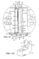
- the movement of the outer segments is controlled by a large cylinder connected by pins 17 to the outer segments 14 and attached to what is called a split J frame.
- the split J frame 10 as shown in Figure 10 provides support for the outer segment 14 and also for an attachment to a frame structure 20 that supports the inner segments 12.
- the split J frame 10 is a casting that provides a flat base and curves upwardly to a pair of slots 11. These slots 11 provide an axle support 7 for the cylinder 6 as shown in Figure 1.
- a reinforcement brace 15 is positioned to provide added structural integrity.
- Each split J frame is 10 is securely attached to the floor and is exposed to approximately 1.8 million pounds force during curing. As shown, the J frames are also cantilevered off the frame 20 and under load can deflect about 0.12 inches (3 mm) or less which is easily accommodated by the pivoting axle support 7 and pin 17 connecting the cylinders 6 to the J frame and the outer segments 14. The entire mold sees approximately 22 million pounds force around the entire periphery.
- the outward cylinders 6 are quite massive and are approximately 16 inches in diameter and have a stroke of approximately 20 inches.
- the inner segments 12 are supported on a frame 20 and the driving mechanism includes an actuating slidable hub assembly 30 that provides radial movement for the inner segments 12 and is co-axially mounted slidably onto a central post or shaft 60.
- the slidable hub assembly 30 has an upper portion 32B and a lower portion 32A as illustrated. Each upper portion 32B and each lower portion 32A has casting locations 33 with a hole 34 for attaching a mechanical link 8. These mechanical links 8 are shown in Figures 1 and 2 and one link 8 is connected by pins 17 to each radially inner segment 12A, 12B.
- the upper hub portion 32B has attached to it through the pivotable links 8 all the inner segments 12B in alternating sequence and interspaced between each inner segment 12B and an upper hub portion 32B of the hub assembly 30 are the links 8.
- This means 36 for providing radial movement of the inner segments 12A, 12B includes not only the hub assembly 30 but also cylinders 31, 35 as clearly illustrated in Figure 2.
- One cylinder 31 moves the lower hub 32A into a lower position such that the linkage mechanism or links 8 are shown almost horizontal.
- the upper portion of the hub 32B is driven by the second cylinder 35 which also moves the hub 32B downward until the linkage mechanism or links 8 connected to that segment 12B are also shown in an almost horizontal position.
- the hub assembly 30 when moved to the mold close position has the holes 34 virtually aligned in both the upper hub portion 32B and the lower hub portion 32A with the centerline of the tread belt 4 as defined as the distance halfway between the lateral edge of the tread belt between the mold portions 16, 18.
- the linkages 8 are pinned at locations 34 of the hub assembly 30 and at the inner segments 12A and 12B at the vertical centerline of the formed tread belt. This ensures that the linkages all line in the same horizontal plane minimizing any off-center loading due to the curing pressure.
- the inner and outer segments 12, 14 are mounted onto a support plate 22 and the support plate 22 has a pair of linear bearings 40 as illustrated in Figure 7 that extend inwardly towards the central shaft 60. These linear bearings 40 provide movement about the inner and outer segments 12, 14.
- the pair of linear bearing rails 41 as shown in Figure 7 have linear bearing blocks 42 attached to the inner and outer segments 12, 14, respectively.
- Each inner segment 12 and each outer segment 14 has four bearing blocks 42 as illustrated, two bearing blocks 42 being slidably attached to each linear bearing rail 41.
- a cooling line 70 is shown.
- the cooling line 70 passes of fluid medium 72 into channeled cooling plate 19, to which inner and outer segments 12, 14 are attached.
- This cooling medium 72 keeps the cooling plate 19 at approximately ambient or room temperature such that the linear bearing blocks attached to the cooling plate 19 remain at a low temperature while the inner and outer segments 12, 14 are heated to provide the curing temperature. It was found that on such a large mold 2 having a diameter of approximately ten feet or greater, that the movement of the linear bearings 40 and the thermal contraction and expansion of the frame 20 had to be controlled such that the frame 20 is generally always at room temperature and not growing substantially with a thermal gradient which would provide an uncontrolled internal diameter based on the growth of the mold 2 and its associated frame 20 over a period of time as the temperature gradient increased. By maintaining the frame 20 at approximately room temperature the dimensional control of the finished product is greatly improved.
- the cooling of the plate 19 between the inner segments 12 and the bearing blocks 42 and the outer segments 14 and the bearing blocks 42 greatly enhances the life of the linear bearings 40.
- the inner segment 12 has fluid medium passages 74 to provide heated fluid 76, either water or steam or any other suitable heating medium, to provide a curing temperature.
- the outside segments 14 also have a fluid medium 76 and passages 74 providing heat to the outer segment 14.
- the parting line 80 for the two mold segments 12, 14, that is, the place where the two mold segments 12, 14 meet is approximately at the radially outer location of the belt layers 5A, 5B, 5C, 5D, preferably between the two radially outermost belt layers 5C, 5D.
- the parting line 80 is shown in a closed position.
- the closure of the parting lines 80 very precisely was achieved in the present invention by providing shims 8A as shown in Fig. 1 in the mechanical links 8.
- the shims 8A were machined precisely to the closed position at temperature for mold curing. This ensures that the parting line 80 starts in a fully closed abutting position or approximately fully closed depending on the size of the tread belt assembly. As the tread belt 4 is being cured and the rubber expands, the parting line 80 is allowed to gap or open. It was determined that providing a parting line 80 towards the radially outer portion of the tread belt 4 enables the tread belt 4 to be performed very uniformly.
- the tread belt 5 has belt layers such that the radially inner belt layer 5A is approximately very close to the lateral edge of the tread belt assembly 4. This being so, if the inner segments 12 have the parting line 80 as shown near the radially inner belt it is possible for the rubber to flow at that area. When that occurs, the tread belt structure 5 distorts the lateral ends creating a weakened position. If the parting line 80 is moved outwardly as illustrated, the tread belt assembly has very little rubber flow movement in the area near the belt structure 5. As illustrated, the parting line 80 is actually achieved by an upper and lower plate 81, 82 that has been bolted with fasteners 90 to the inner segment 12. This effectively moves the parting line 80 outwardly towards the outer segment 14 and closer to the tread rubber 9.
- the tread belt assembly 4 has a radially outer tread area 9 and a radially inner surface 3 having a plurality of ribs 3A and grooves 38.
- the radially inner surface 3 provides an interface between a carcass or casing assembly to which the tread belt 4 is to be later mounted for use.
- Above the inner surface 3 is the entire tread belt reinforcing structure 5.
- the tread belt reinforcing structure includes a first belt layer 5A including zero degree wires circumferentially wound about the tread belt assembly 4 and interposed between the circumferential wire layers 5A and a radially outermost belt layer 90 are two cross plies 5B, 5C, each cross ply 5B, 5C having lateral edges being moved axially inwardly from the circumferential belt wire 5A lateral edges such that each radially outer belt layer 5B, 5C, 5D, respectively, is slightly narrower than the radially inner adjacent layer.
- Outward of the two cross ply layers 5B, 5C as illustrated is a 90° wire layer 50 which provides tremendous axial strength.
- the parting line 80 is positioned very close to this 90° wire layer 50.
- parting line 80 is in alignment with a 90° layer 50 growth in the lateral extent is resisted by the 90° wires. This provides substantial strength and helps prevent buckling or other nonuniformities to occur in the lower layers 5A, 5B and 5C.
- a further benefit is that as the parting line 80 is closer to the narrowest belt 50, far less movement of the rubber compound around the belt structure 5 can occur and the primary movement will be from the tread rubber 9 which is of no consequence. While these features may seem subtle, they are extremely important in manufacturing a quality tread belt structure 4. For example, a typical large off-road pneumatic radial tire has the largest or widest belt layer 3.65 inches from the tread's lateral edge.
- a similarly sized two-piece tread belt has the widest belt layer 1.25 inches or approximately 300% closer to the lateral edge of the mold. Accordingly, the sensitivity to belt distortion at the lateral edges of the tread belt 4 is significantly increased. Avoidance of undesirable flows of rubber are mandated because the resultant distortion of the belt layers 5A through 5D can adversely affect the durability of the tread belt 4.
Landscapes
- Engineering & Computer Science (AREA)
- Mechanical Engineering (AREA)
- Moulds For Moulding Plastics Or The Like (AREA)
- Heating, Cooling, Or Curing Plastics Or The Like In General (AREA)
- Tyre Moulding (AREA)
- Tires In General (AREA)
Abstract
Description
Claims (9)
a plurality of radially movable and outwardly expandable inner segments (12A, 12B) for forming the inner surface (3) of the tread belt (4); and
a plurality of radially movable and contracting outer segments (14A, 14B) for forming the outer surface of the tread belt (14),
characterized in that wherein the radially inner and radially outer segments form a mold parting line (80) at a location radially outward of a midpoint of the belt reinforcing structure (5) of the tread belt (4) at a location greater than 50% of the radial thickness (t) as measured from the radially innermost surface of the belt reinforcing structure (5).
a plurality of outer tread belt forming segments (14A, 14B);
a plurality of radially movable and outwardly expandable inner segments (12A, 12B) for forming the inner surface (3) of the tread belt (4);
a slidable hub assembly (30), the slidable hub assembly (30) having a central shaft (60), an upper hub portion (32B) and a lower hub portion (32A) each slidably mounted onto the central shaft (60); each upper and lower hub portions having a plurality of linkage arms (8) pivotably connected to the respective hub and the radially inner segments, each circumferentially adjacent segment being connected to either an upper or lower hub in an alternating pattern, the movement of one hub relative to the other being independently actuated by one or more means (36) for moving the hub portions, and wherein the movement of the lower and upper hub into interlocking alignment moves the inner segments (12A, 12B) to form an annular ring.
a radially outer tread;
a belt reinforcing structure (5), the belt structure (5) having at least a radially inner layer of 0° circumferentially extending wires, a pair of cross ply layers and a radially outer layer of 90° laterally extending wires; and
a parting line (80) radially outward of the radially inner layer and at least one of the layers of the cross ply layers.
Priority Applications (1)
| Application Number | Priority Date | Filing Date | Title |
|---|---|---|---|
| EP08156750A EP1961543A1 (en) | 2003-10-03 | 2004-09-23 | A mold for curing annular or ring treads |
Applications Claiming Priority (2)
| Application Number | Priority Date | Filing Date | Title |
|---|---|---|---|
| US678997 | 1996-07-12 | ||
| US10/678,997 US7189069B2 (en) | 2003-10-03 | 2003-10-03 | Mold for forming an annular tread belt |
Related Child Applications (1)
| Application Number | Title | Priority Date | Filing Date |
|---|---|---|---|
| EP08156750A Division EP1961543A1 (en) | 2003-10-03 | 2004-09-23 | A mold for curing annular or ring treads |
Publications (3)
| Publication Number | Publication Date |
|---|---|
| EP1520674A2 true EP1520674A2 (en) | 2005-04-06 |
| EP1520674A3 EP1520674A3 (en) | 2006-04-19 |
| EP1520674B1 EP1520674B1 (en) | 2008-05-28 |
Family
ID=34314084
Family Applications (2)
| Application Number | Title | Priority Date | Filing Date |
|---|---|---|---|
| EP04104628A Expired - Lifetime EP1520674B1 (en) | 2003-10-03 | 2004-09-23 | A mold and method of molding annular tread belt |
| EP08156750A Withdrawn EP1961543A1 (en) | 2003-10-03 | 2004-09-23 | A mold for curing annular or ring treads |
Family Applications After (1)
| Application Number | Title | Priority Date | Filing Date |
|---|---|---|---|
| EP08156750A Withdrawn EP1961543A1 (en) | 2003-10-03 | 2004-09-23 | A mold for curing annular or ring treads |
Country Status (6)
| Country | Link |
|---|---|
| US (1) | US7189069B2 (en) |
| EP (2) | EP1520674B1 (en) |
| JP (1) | JP4469247B2 (en) |
| BR (1) | BRPI0404104A (en) |
| DE (1) | DE602004014080D1 (en) |
| ES (1) | ES2306961T3 (en) |
Cited By (2)
| Publication number | Priority date | Publication date | Assignee | Title |
|---|---|---|---|---|
| CN109689328A (en) * | 2016-08-12 | 2019-04-26 | 通伊欧轮胎株式会社 | The manufacturing method of tire curing unit and tire |
| EP4378675A1 (en) * | 2022-11-30 | 2024-06-05 | The Goodyear Tire & Rubber Company | Mold for producing annular rubber component |
Families Citing this family (7)
| Publication number | Priority date | Publication date | Assignee | Title |
|---|---|---|---|---|
| BRPI0822855A2 (en) * | 2008-06-27 | 2015-06-30 | Michelin Rech Tech | Tire Curing Mold |
| EP2296860B1 (en) * | 2008-06-30 | 2015-01-28 | MICHELIN Recherche et Technique S.A. | Tire mold with positive mold opening system |
| ES2370466T3 (en) * | 2009-09-30 | 2011-12-16 | Eurocopter Deutschland Gmbh | CONTROLLED CIRCUNFERENTIAL IMPREGNATION DEVICE. |
| WO2012150948A1 (en) | 2011-04-30 | 2012-11-08 | Michelin Recherche Et Technique S.A. | Methods and apparatus for joining treads |
| US8512614B2 (en) | 2011-06-20 | 2013-08-20 | Dayco Ip Holdings, Llc | Modular molding system |
| BR112013033157A2 (en) | 2011-06-30 | 2017-01-31 | Michelin & Cie | methods and apparatus for installing a tread ring and a tire casing |
| US10562250B2 (en) * | 2017-07-17 | 2020-02-18 | American Kenda Rubber Industrial Co., Ltd. | Non-pneumatic tire tread layer mold and molding process |
Family Cites Families (17)
| Publication number | Priority date | Publication date | Assignee | Title |
|---|---|---|---|---|
| US2381395A (en) * | 1943-07-08 | 1945-08-07 | Firestone Tire & Rubber Co | Vulcanizing mold |
| CH399734A (en) * | 1963-07-27 | 1965-09-30 | Pirelli | Procedure for printing a relief design along the perimeter band, in the plastic state, of a flexible ring and device for carrying out this procedure |
| US3659976A (en) * | 1970-08-21 | 1972-05-02 | Arsenty Vasilievich Yavorsky | Apparatus for molding and vulcanization of annular rubber articles |
| US3791897A (en) | 1971-06-16 | 1974-02-12 | Bombardier Ltd | Method and apparatus for making endless belts |
| IT1010109B (en) | 1974-04-26 | 1977-01-10 | Pirelli | MOLD FOR THE MANUFACTURING OF DOUBLE-TOOTHED TIMING BELTS AND TIMING BELTS SO OBTAINED |
| US4207052A (en) | 1976-07-16 | 1980-06-10 | Caterpillar Tractor Co. | Curing mold for curing replaceable tread and track belts |
| US4263083A (en) * | 1979-07-20 | 1981-04-21 | The Goodyear Tire & Rubber Company | Building and curing an inextensible belt structure for a tire assembly |
| JPS58163638A (en) | 1982-03-25 | 1983-09-28 | Mitsuboshi Belting Ltd | Fabricated mold for manufacture of toothed belt made of rubber |
| IT1234666B (en) | 1989-09-21 | 1992-05-26 | Mai Spa | PROCEDURE FOR THE REALIZATION OF RUBBER TRACKS AND TRACK SO MADE |
| US5066448A (en) * | 1990-10-03 | 1991-11-19 | The Goodyear Tire & Rubber Company | Tread removal method and apparatus |
| JPH07144375A (en) | 1993-11-22 | 1995-06-06 | Sumitomo Rubber Ind Ltd | Tire band winding equipment |
| DE69715756T2 (en) * | 1996-08-20 | 2003-02-06 | Sumitomo Rubber Industries Ltd., Kobe | Method and device for producing a radial pneumatic tire |
| US6086811A (en) | 1998-04-29 | 2000-07-11 | The Goodyear Tire & Rubber Company | Molding system for rubber tractor tracks |
| US6177042B1 (en) * | 1998-11-23 | 2001-01-23 | The Goodyear Tire & Rubber Company | Method and apparatus for making integral rubber tractor tracks |
| DE60125126T2 (en) | 2000-10-18 | 2007-04-12 | Sumitomo Rubber Industries Ltd., Kobe | tire |
| DE60238610D1 (en) | 2001-07-19 | 2011-01-27 | Pirelli | TIRES FOR MOTOR VEHICLES WITH WAVY MONOFILAMENTS IN BELT REINFORCEMENT LAYER |
| US6554377B2 (en) * | 2001-07-19 | 2003-04-29 | The Goodyear Tire & Rubber Company | Rubber track and improved method and method for producing the track |
-
2003
- 2003-10-03 US US10/678,997 patent/US7189069B2/en not_active Expired - Fee Related
-
2004
- 2004-09-23 ES ES04104628T patent/ES2306961T3/en not_active Expired - Lifetime
- 2004-09-23 DE DE602004014080T patent/DE602004014080D1/en not_active Expired - Fee Related
- 2004-09-23 EP EP04104628A patent/EP1520674B1/en not_active Expired - Lifetime
- 2004-09-23 EP EP08156750A patent/EP1961543A1/en not_active Withdrawn
- 2004-09-27 BR BR0404104-6A patent/BRPI0404104A/en not_active IP Right Cessation
- 2004-09-28 JP JP2004281094A patent/JP4469247B2/en not_active Expired - Lifetime
Cited By (2)
| Publication number | Priority date | Publication date | Assignee | Title |
|---|---|---|---|---|
| CN109689328A (en) * | 2016-08-12 | 2019-04-26 | 通伊欧轮胎株式会社 | The manufacturing method of tire curing unit and tire |
| EP4378675A1 (en) * | 2022-11-30 | 2024-06-05 | The Goodyear Tire & Rubber Company | Mold for producing annular rubber component |
Also Published As
| Publication number | Publication date |
|---|---|
| BRPI0404104A (en) | 2005-05-24 |
| ES2306961T3 (en) | 2008-11-16 |
| EP1520674A3 (en) | 2006-04-19 |
| JP4469247B2 (en) | 2010-05-26 |
| DE602004014080D1 (en) | 2008-07-10 |
| US20050073074A1 (en) | 2005-04-07 |
| US7189069B2 (en) | 2007-03-13 |
| EP1961543A1 (en) | 2008-08-27 |
| EP1520674B1 (en) | 2008-05-28 |
| JP2005111989A (en) | 2005-04-28 |
Similar Documents
| Publication | Publication Date | Title |
|---|---|---|
| FI87163C (en) | Rigid mold for casting and vulcanization of outer tires | |
| US7628599B2 (en) | Self-locking tire mold apparatus | |
| JP3325580B2 (en) | Centrally divided and arcuate mold for curing pneumatic tires | |
| US3464090A (en) | Tire curing press | |
| US3358330A (en) | Apparatus for producing the tread band of flexible tread rings while in a plastic state | |
| EP1520674B1 (en) | A mold and method of molding annular tread belt | |
| US20130180646A1 (en) | Method and apparatus for manufacturing tyres | |
| JPS637937B2 (en) | ||
| US7001163B2 (en) | Mold and method of molding annular tread | |
| US9724884B2 (en) | Equipment for moulding and curing a green tyre | |
| AU704846B2 (en) | Apparatus and method for curing endless rubber track | |
| EP1629963B1 (en) | Tire curing bladder | |
| JPH0259052B2 (en) | ||
| GB1592854A (en) | Method of building tyres | |
| US20060125147A1 (en) | Segmented tire mold for off-road-vehicle tires | |
| US7833374B2 (en) | Radially expansible tire assembly drum and method for forming tires | |
| JPS6011603B2 (en) | Vulcanizing equipment for replaceable tread belts and cover belts | |
| US6607373B2 (en) | Resilient mold for tread | |
| JPH0423632B2 (en) | ||
| CA1096115A (en) | Centering a tire in a mold |
Legal Events
| Date | Code | Title | Description |
|---|---|---|---|
| PUAI | Public reference made under article 153(3) epc to a published international application that has entered the european phase |
Free format text: ORIGINAL CODE: 0009012 |
|
| AK | Designated contracting states |
Kind code of ref document: A2 Designated state(s): AT BE BG CH CY CZ DE DK EE ES FI FR GB GR HU IE IT LI LU MC NL PL PT RO SE SI SK TR |
|
| AX | Request for extension of the european patent |
Extension state: AL HR LT LV MK |
|
| PUAL | Search report despatched |
Free format text: ORIGINAL CODE: 0009013 |
|
| AK | Designated contracting states |
Kind code of ref document: A3 Designated state(s): AT BE BG CH CY CZ DE DK EE ES FI FR GB GR HU IE IT LI LU MC NL PL PT RO SE SI SK TR |
|
| AX | Request for extension of the european patent |
Extension state: AL HR LT LV MK |
|
| RIC1 | Information provided on ipc code assigned before grant |
Ipc: B29C 33/44 20060101ALI20060301BHEP Ipc: B29D 30/70 20060101ALI20060301BHEP Ipc: B60C 11/00 20060101ALI20060301BHEP Ipc: B29D 30/52 20060101ALI20060301BHEP Ipc: B29C 33/24 20060101AFI20041217BHEP |
|
| 17P | Request for examination filed |
Effective date: 20061019 |
|
| 17Q | First examination report despatched |
Effective date: 20061113 |
|
| AKX | Designation fees paid |
Designated state(s): DE ES FR |
|
| GRAP | Despatch of communication of intention to grant a patent |
Free format text: ORIGINAL CODE: EPIDOSNIGR1 |
|
| GRAS | Grant fee paid |
Free format text: ORIGINAL CODE: EPIDOSNIGR3 |
|
| GRAA | (expected) grant |
Free format text: ORIGINAL CODE: 0009210 |
|
| AK | Designated contracting states |
Kind code of ref document: B1 Designated state(s): DE ES FR |
|
| REF | Corresponds to: |
Ref document number: 602004014080 Country of ref document: DE Date of ref document: 20080710 Kind code of ref document: P |
|
| PGFP | Annual fee paid to national office [announced via postgrant information from national office to epo] |
Ref country code: ES Payment date: 20080728 Year of fee payment: 5 |
|
| REG | Reference to a national code |
Ref country code: ES Ref legal event code: FG2A Ref document number: 2306961 Country of ref document: ES Kind code of ref document: T3 |
|
| PGFP | Annual fee paid to national office [announced via postgrant information from national office to epo] |
Ref country code: FR Payment date: 20080707 Year of fee payment: 5 |
|
| PGFP | Annual fee paid to national office [announced via postgrant information from national office to epo] |
Ref country code: DE Payment date: 20080731 Year of fee payment: 5 |
|
| PLBE | No opposition filed within time limit |
Free format text: ORIGINAL CODE: 0009261 |
|
| STAA | Information on the status of an ep patent application or granted ep patent |
Free format text: STATUS: NO OPPOSITION FILED WITHIN TIME LIMIT |
|
| 26N | No opposition filed |
Effective date: 20090303 |
|
| REG | Reference to a national code |
Ref country code: FR Ref legal event code: ST Effective date: 20100531 |
|
| PG25 | Lapsed in a contracting state [announced via postgrant information from national office to epo] |
Ref country code: DE Free format text: LAPSE BECAUSE OF NON-PAYMENT OF DUE FEES Effective date: 20100401 Ref country code: FR Free format text: LAPSE BECAUSE OF NON-PAYMENT OF DUE FEES Effective date: 20090930 |
|
| REG | Reference to a national code |
Ref country code: ES Ref legal event code: FD2A Effective date: 20110711 |
|
| PG25 | Lapsed in a contracting state [announced via postgrant information from national office to epo] |
Ref country code: ES Free format text: LAPSE BECAUSE OF NON-PAYMENT OF DUE FEES Effective date: 20110629 |
|
| PG25 | Lapsed in a contracting state [announced via postgrant information from national office to epo] |
Ref country code: ES Free format text: LAPSE BECAUSE OF NON-PAYMENT OF DUE FEES Effective date: 20090924 |