EP1520314B1 - Fuel cell with evaporative cooling and humidification - Google Patents
Fuel cell with evaporative cooling and humidification Download PDFInfo
- Publication number
- EP1520314B1 EP1520314B1 EP03735632.6A EP03735632A EP1520314B1 EP 1520314 B1 EP1520314 B1 EP 1520314B1 EP 03735632 A EP03735632 A EP 03735632A EP 1520314 B1 EP1520314 B1 EP 1520314B1
- Authority
- EP
- European Patent Office
- Prior art keywords
- openings
- fluid
- cells
- generator according
- collection
- Prior art date
- Legal status (The legal status is an assumption and is not a legal conclusion. Google has not performed a legal analysis and makes no representation as to the accuracy of the status listed.)
- Expired - Lifetime
Links
- 239000000446 fuel Substances 0.000 title description 10
- 238000001816 cooling Methods 0.000 title description 6
- 239000000376 reactant Substances 0.000 claims description 74
- 239000012530 fluid Substances 0.000 claims description 64
- 238000006243 chemical reaction Methods 0.000 claims description 56
- 238000002347 injection Methods 0.000 claims description 37
- 239000007924 injection Substances 0.000 claims description 37
- XLYOFNOQVPJJNP-UHFFFAOYSA-N water Substances O XLYOFNOQVPJJNP-UHFFFAOYSA-N 0.000 claims description 37
- 239000012528 membrane Substances 0.000 claims description 35
- 238000007789 sealing Methods 0.000 claims description 33
- 239000007788 liquid Substances 0.000 claims description 32
- 239000007795 chemical reaction product Substances 0.000 claims description 20
- 239000012809 cooling fluid Substances 0.000 claims description 14
- 238000009826 distribution Methods 0.000 claims description 8
- 238000010438 heat treatment Methods 0.000 claims description 6
- 238000007599 discharging Methods 0.000 claims 2
- 239000007800 oxidant agent Substances 0.000 description 9
- 230000001590 oxidative effect Effects 0.000 description 9
- 230000015572 biosynthetic process Effects 0.000 description 8
- 230000008878 coupling Effects 0.000 description 6
- 238000010168 coupling process Methods 0.000 description 6
- 238000005859 coupling reaction Methods 0.000 description 6
- 238000001704 evaporation Methods 0.000 description 4
- 238000006722 reduction reaction Methods 0.000 description 4
- OKKJLVBELUTLKV-UHFFFAOYSA-N Methanol Chemical compound OC OKKJLVBELUTLKV-UHFFFAOYSA-N 0.000 description 3
- 230000008901 benefit Effects 0.000 description 3
- 230000008020 evaporation Effects 0.000 description 3
- 230000007062 hydrolysis Effects 0.000 description 3
- 238000006460 hydrolysis reaction Methods 0.000 description 3
- 230000007246 mechanism Effects 0.000 description 3
- 229910052751 metal Inorganic materials 0.000 description 3
- 239000000047 product Substances 0.000 description 3
- 239000000243 solution Substances 0.000 description 3
- LFQSCWFLJHTTHZ-UHFFFAOYSA-N Ethanol Chemical compound CCO LFQSCWFLJHTTHZ-UHFFFAOYSA-N 0.000 description 2
- UFHFLCQGNIYNRP-UHFFFAOYSA-N Hydrogen Chemical compound [H][H] UFHFLCQGNIYNRP-UHFFFAOYSA-N 0.000 description 2
- 238000004026 adhesive bonding Methods 0.000 description 2
- 238000004873 anchoring Methods 0.000 description 2
- 230000006835 compression Effects 0.000 description 2
- 238000007906 compression Methods 0.000 description 2
- 230000000694 effects Effects 0.000 description 2
- 229920001971 elastomer Polymers 0.000 description 2
- 239000000806 elastomer Substances 0.000 description 2
- 239000001257 hydrogen Substances 0.000 description 2
- 229910052739 hydrogen Inorganic materials 0.000 description 2
- 238000000465 moulding Methods 0.000 description 2
- 229920000642 polymer Polymers 0.000 description 2
- 229920001296 polysiloxane Polymers 0.000 description 2
- 230000009467 reduction Effects 0.000 description 2
- 238000000926 separation method Methods 0.000 description 2
- 239000007779 soft material Substances 0.000 description 2
- 239000000126 substance Substances 0.000 description 2
- 150000001298 alcohols Chemical class 0.000 description 1
- QVGXLLKOCUKJST-UHFFFAOYSA-N atomic oxygen Chemical compound [O] QVGXLLKOCUKJST-UHFFFAOYSA-N 0.000 description 1
- 230000003197 catalytic effect Effects 0.000 description 1
- 238000006555 catalytic reaction Methods 0.000 description 1
- 150000001768 cations Chemical class 0.000 description 1
- 230000003247 decreasing effect Effects 0.000 description 1
- 230000000593 degrading effect Effects 0.000 description 1
- 239000008367 deionised water Substances 0.000 description 1
- 238000001035 drying Methods 0.000 description 1
- 230000002708 enhancing effect Effects 0.000 description 1
- 239000008246 gaseous mixture Substances 0.000 description 1
- 230000036571 hydration Effects 0.000 description 1
- 238000006703 hydration reaction Methods 0.000 description 1
- 150000002500 ions Chemical class 0.000 description 1
- 238000004519 manufacturing process Methods 0.000 description 1
- 239000000463 material Substances 0.000 description 1
- 239000002184 metal Substances 0.000 description 1
- -1 methanol or ethanol Chemical class 0.000 description 1
- 238000000034 method Methods 0.000 description 1
- 238000012986 modification Methods 0.000 description 1
- 230000004048 modification Effects 0.000 description 1
- 238000009828 non-uniform distribution Methods 0.000 description 1
- 239000001301 oxygen Substances 0.000 description 1
- 229910052760 oxygen Inorganic materials 0.000 description 1
- 230000008569 process Effects 0.000 description 1
- 229920006395 saturated elastomer Polymers 0.000 description 1
- 238000009827 uniform distribution Methods 0.000 description 1
Images




Classifications
-
- H—ELECTRICITY
- H01—ELECTRIC ELEMENTS
- H01M—PROCESSES OR MEANS, e.g. BATTERIES, FOR THE DIRECT CONVERSION OF CHEMICAL ENERGY INTO ELECTRICAL ENERGY
- H01M8/00—Fuel cells; Manufacture thereof
- H01M8/02—Details
-
- H—ELECTRICITY
- H01—ELECTRIC ELEMENTS
- H01M—PROCESSES OR MEANS, e.g. BATTERIES, FOR THE DIRECT CONVERSION OF CHEMICAL ENERGY INTO ELECTRICAL ENERGY
- H01M8/00—Fuel cells; Manufacture thereof
- H01M8/04—Auxiliary arrangements, e.g. for control of pressure or for circulation of fluids
- H01M8/04007—Auxiliary arrangements, e.g. for control of pressure or for circulation of fluids related to heat exchange
- H01M8/04029—Heat exchange using liquids
-
- H—ELECTRICITY
- H01—ELECTRIC ELEMENTS
- H01M—PROCESSES OR MEANS, e.g. BATTERIES, FOR THE DIRECT CONVERSION OF CHEMICAL ENERGY INTO ELECTRICAL ENERGY
- H01M8/00—Fuel cells; Manufacture thereof
- H01M8/02—Details
- H01M8/0202—Collectors; Separators, e.g. bipolar separators; Interconnectors
- H01M8/0267—Collectors; Separators, e.g. bipolar separators; Interconnectors having heating or cooling means, e.g. heaters or coolant flow channels
-
- H—ELECTRICITY
- H01—ELECTRIC ELEMENTS
- H01M—PROCESSES OR MEANS, e.g. BATTERIES, FOR THE DIRECT CONVERSION OF CHEMICAL ENERGY INTO ELECTRICAL ENERGY
- H01M8/00—Fuel cells; Manufacture thereof
- H01M8/02—Details
- H01M8/0271—Sealing or supporting means around electrodes, matrices or membranes
-
- H—ELECTRICITY
- H01—ELECTRIC ELEMENTS
- H01M—PROCESSES OR MEANS, e.g. BATTERIES, FOR THE DIRECT CONVERSION OF CHEMICAL ENERGY INTO ELECTRICAL ENERGY
- H01M8/00—Fuel cells; Manufacture thereof
- H01M8/02—Details
- H01M8/0271—Sealing or supporting means around electrodes, matrices or membranes
- H01M8/0273—Sealing or supporting means around electrodes, matrices or membranes with sealing or supporting means in the form of a frame
-
- H—ELECTRICITY
- H01—ELECTRIC ELEMENTS
- H01M—PROCESSES OR MEANS, e.g. BATTERIES, FOR THE DIRECT CONVERSION OF CHEMICAL ENERGY INTO ELECTRICAL ENERGY
- H01M8/00—Fuel cells; Manufacture thereof
- H01M8/04—Auxiliary arrangements, e.g. for control of pressure or for circulation of fluids
-
- H—ELECTRICITY
- H01—ELECTRIC ELEMENTS
- H01M—PROCESSES OR MEANS, e.g. BATTERIES, FOR THE DIRECT CONVERSION OF CHEMICAL ENERGY INTO ELECTRICAL ENERGY
- H01M8/00—Fuel cells; Manufacture thereof
- H01M8/04—Auxiliary arrangements, e.g. for control of pressure or for circulation of fluids
- H01M8/04007—Auxiliary arrangements, e.g. for control of pressure or for circulation of fluids related to heat exchange
- H01M8/04067—Heat exchange or temperature measuring elements, thermal insulation, e.g. heat pipes, heat pumps, fins
- H01M8/04074—Heat exchange unit structures specially adapted for fuel cell
-
- H—ELECTRICITY
- H01—ELECTRIC ELEMENTS
- H01M—PROCESSES OR MEANS, e.g. BATTERIES, FOR THE DIRECT CONVERSION OF CHEMICAL ENERGY INTO ELECTRICAL ENERGY
- H01M8/00—Fuel cells; Manufacture thereof
- H01M8/04—Auxiliary arrangements, e.g. for control of pressure or for circulation of fluids
- H01M8/04082—Arrangements for control of reactant parameters, e.g. pressure or concentration
- H01M8/04089—Arrangements for control of reactant parameters, e.g. pressure or concentration of gaseous reactants
- H01M8/04119—Arrangements for control of reactant parameters, e.g. pressure or concentration of gaseous reactants with simultaneous supply or evacuation of electrolyte; Humidifying or dehumidifying
- H01M8/04126—Humidifying
- H01M8/04134—Humidifying by coolants
-
- H—ELECTRICITY
- H01—ELECTRIC ELEMENTS
- H01M—PROCESSES OR MEANS, e.g. BATTERIES, FOR THE DIRECT CONVERSION OF CHEMICAL ENERGY INTO ELECTRICAL ENERGY
- H01M8/00—Fuel cells; Manufacture thereof
- H01M8/24—Grouping of fuel cells, e.g. stacking of fuel cells
- H01M8/241—Grouping of fuel cells, e.g. stacking of fuel cells with solid or matrix-supported electrolytes
- H01M8/242—Grouping of fuel cells, e.g. stacking of fuel cells with solid or matrix-supported electrolytes comprising framed electrodes or intermediary frame-like gaskets
-
- H—ELECTRICITY
- H01—ELECTRIC ELEMENTS
- H01M—PROCESSES OR MEANS, e.g. BATTERIES, FOR THE DIRECT CONVERSION OF CHEMICAL ENERGY INTO ELECTRICAL ENERGY
- H01M8/00—Fuel cells; Manufacture thereof
- H01M8/24—Grouping of fuel cells, e.g. stacking of fuel cells
- H01M8/2457—Grouping of fuel cells, e.g. stacking of fuel cells with both reactants being gaseous or vaporised
-
- H—ELECTRICITY
- H01—ELECTRIC ELEMENTS
- H01M—PROCESSES OR MEANS, e.g. BATTERIES, FOR THE DIRECT CONVERSION OF CHEMICAL ENERGY INTO ELECTRICAL ENERGY
- H01M8/00—Fuel cells; Manufacture thereof
- H01M8/24—Grouping of fuel cells, e.g. stacking of fuel cells
- H01M8/2465—Details of groupings of fuel cells
- H01M8/2483—Details of groupings of fuel cells characterised by internal manifolds
-
- Y—GENERAL TAGGING OF NEW TECHNOLOGICAL DEVELOPMENTS; GENERAL TAGGING OF CROSS-SECTIONAL TECHNOLOGIES SPANNING OVER SEVERAL SECTIONS OF THE IPC; TECHNICAL SUBJECTS COVERED BY FORMER USPC CROSS-REFERENCE ART COLLECTIONS [XRACs] AND DIGESTS
- Y02—TECHNOLOGIES OR APPLICATIONS FOR MITIGATION OR ADAPTATION AGAINST CLIMATE CHANGE
- Y02E—REDUCTION OF GREENHOUSE GAS [GHG] EMISSIONS, RELATED TO ENERGY GENERATION, TRANSMISSION OR DISTRIBUTION
- Y02E60/00—Enabling technologies; Technologies with a potential or indirect contribution to GHG emissions mitigation
- Y02E60/30—Hydrogen technology
- Y02E60/50—Fuel cells
Definitions
- the present invention relates to a membrane electrochemical generator with direct injection of liquid water into the gaseous reactants.
- a membrane electrochemical generator is formed by a multiplicity of reaction cells mutually connected in electrical series and assembled according to a bipolar configuration.
- Each reaction cell converts the chemical energy generated during the reaction of a fuel with an oxidant without degrading it completely to thermal energy, and therefore without being subject to the limitations of Carnot's cycle. More specifically, the fuel is supplied to the anodic chamber of the reaction cell and consists for instance of a hydrogen-rich gaseous mixture or of solutions of light alcohols, such as methanol or ethanol, while the oxidant is supplied to the cathodic chamber of the same cell and consists for instance of air or oxygen.
- the fuel is catalytically electro-oxidised in the anodic chamber releasing protons H + and electrons e - which are consumed in the cathodic chamber through a catalytic reaction of oxidant electro-reduction, with production of water.
- a proton-exchange membrane which separates the anodic and the cathodic chamber allows the continuous flow of protons H + from the anodic chamber to the cathodic chamber while simultaneously hindering the passage of electrons e - , which conversely takes place through an external electric circuit. In this way, the difference of electric potential established at the poles of the reaction cell is maximised.
- the proton-exchange membranes commonly employed in membrane electrochemical generators consist of a chemically inert polymer, partially functionalised with groups capable of undergoing an acid-base hydrolysis in the presence of liquid water, with consequent separation of electrical charge. More precisely, the above hydrolysis consists of the release of positive ions (cations) and the formation of fixed negative charges on the polymer.
- the gaseous reactants fuel and oxidant
- the electrochemical generator saturated with water vapour and at a temperature close to that of the reaction cells by means of expensive and complex saturation devices, placed outside the electrochemical generator itself.
- the known electrochemical generators are also provided with suitable cooling devices which accomplish the withdrawal of the heat produced during the functioning of the generator itself, through thermal exchange with a circulating fluid (for instance deionised water).
- a circulating fluid for instance deionised water.
- the heat must be efficiently withdrawn from the electrochemical generator to allow the thermal control thereof not only due to the limited thermal stability of the proton-exchange membranes, usually unfit for operating at temperatures above 100°C, but also to limit as far as possible the evaporation of the water produced in the course of the electro-reduction reaction and its consequent removal by the flow of inerts and unconverted reactants exiting the generator, with the consequent risk of membrane dry-out.
- the direct injection of the calibrated flow of liquid water takes place peripherally to the active area of each reaction cell and transversally to the flow of gaseous reactants.
- Such a mode for direct injection of liquid water due to the reduced momentum of the latter and to the adhesion phenomena to the walls of the sealing gaskets, may determine a non uniform distribution of water within the active area of each cell, with consequent formation of non moistened, hot and incipiently drying regions. This has the effect of provoking the membrane drying-out and thus the reduction of their operative lifetime besides hampering the mechanism of water evaporation, with consequent increment of the liquid water flow-rate necessary to the thermal control of the electrochemical generator.
- the object of the present invention is to provide a membrane electrochemical generator free of the described drawbacks.
- a membrane electrochemical generator is realised as independently defined in claims 1 and 8.
- FIG. 1 shows a first embodiment of a membrane electrochemical generator according to the invention.
- the electrochemical generator 1 comprises a multiplicity of reaction cells 2 mutually connected in series and assembled according to a filter-press type configuration.
- each reaction cell 2 is delimited by a pair of conductive bipolar plates 3, with planar faces, among which are comprised, proceeding outwards, the proton-exchange membrane 4; a pair of porous electrodes 5; a pair of catalytic layers 6 deposited at the interface between membrane 4 and each of the porous electrodes 5; a pair of current collectors/distributors 7, realised by means of a reticulated metallic element of the type described in US Patent 5,482,792 , electrically connecting the conductive bipolar plates 3 to the porous electrodes 5 while simultaneously distributing the gaseous reactants; a sealing gasket pair 8a, 8b consisting of an anodic sealing gasket 8a and a cathodic sealing gasket 8b.
- the anodic sealing gasket 8a is directed to seal the periphery of the anodic chamber 9 of the reaction cell 2 in order to avoid the leakage of fuel (hydrogen in particular), while the cathodic sealing gasket 8b is directed to seal the periphery of the cathodic chamber 10 of the reaction cell 2 in order to avoid the leakage of oxidant (air in particular).
- the anodic and cathodic sealing gaskets 8a, 8b are also directed to realise the seat for the current collectors/distributors 7.
- the conductive bipolar plates 3 have a substantially rectangular shape and each of them presents a perimetrical portion 11 provided with: first and second upper openings 12, 13 for the passage of the gaseous reactants, respectively fuel and oxidant; first and second lower openings 14, 15 for the discharge of the reaction products mixed with the optional residual reactants; side openings 16 for the passage of a cooling fluid, in particular liquid water.
- the perimetrical portion 11 is also provided with a multiplicity of holes 17 for the housing of tie-rods by means of which the tightening of the electrochemical generator 1 is accomplished.
- the coupling between the first and the second upper openings 12, 13 of all the conductive bipolar plates 3 determines the formation of two upper longitudinal ducts 18 while the coupling between the first and the second lower openings 14, 15 of all the conductive bipolar plates 3 determines the formation of two lower longitudinal ducts 19.
- the two upper longitudinal ducts 18, only one of which is shown in figure 1 define the feeding manifolds of the gaseous reactants while the two lower longitudinal ducts 19, only one of which is shown in figure 1 , define the discharge manifolds of the reaction products mixed with the optional residual reactants.
- the lower longitudinal ducts 19 can be employed as feeding manifolds, and the upper longitudinal ducts 18 as discharge manifolds.
- the coupling between the side openings 16 of all the conductive bipolar plates 3 determines the formation of side ducts, not shown in figure 1 , for the passage of the liquid water.
- Each conductive bipolar plate 3 is also provided with a multiplicity of fluid injection calibrated holes 20, all having the same diameter (for instance comprised between 0,2 mm ⁇ 1 mm), through which the liquid water flowing in the side ducts of the electrochemical generator 1 is injected into the reaction cells 2, as will be better explained hereafter.
- the fluid injection calibrated holes 20 are mutually aligned in order to ensure a homogeneous distribution of the liquid water and are placed below the first and second upper openings 12, 13.
- the anodic and cathodic sealing gaskets 8a, 8b of each reaction cell 2 have a substantially rectangular shape and present respective first and second upper openings 8a 1 , 8a 2 , 8b 1 , 8b 2 , for the passage of the gaseous reactants; respective first and second lower openings 8a 3 , 8a 4 , 8b 3 , 8b 4 , for the discharge of the reaction products mixed with the optional residual reactants; respective side openings 8a 5 , 8b 5 for the passage of liquid water.
- the first upper openings 8a 1 (through which the fuel passes) and the second lower openings 8a 4 of the anodic gasket 8a are connected to the anodic chamber 9 through, respectively, distribution channels 21 a and discharge channels 21 b, obtained within the thickness of the same anodic sealing gasket ( figure 3a ).
- the second upper openings 8b 2 (through which the oxidant passes) and the first lower openings 8b 3 of the cathodic sealing gasket 8b are connected to the cathodic chamber 10 respectively through the distribution channels 23a and the discharge channels 23b, obtained within the thickness of the same cathodic sealing gasket ( figure 3b ).
- the distributing and discharge channels 21a, 21b, 23a and 23b have a comb-like structure allowing them to distribute and collect within each reaction cell 2 the gaseous reactants and the reaction products, the latter mixed with the optional residual reactants, in a uniform fashion.
- the anodic sealing gasket 8a is also provided with fluid collection channels 22 connected with the side openings 8a 5 .
- the fluid collection channels 22 can also be connected to the distribution channels 21 a ( figure 3c ).
- the first and the second upper openings 8a 1 , 8a 2 , 8b 1 , 8b 2 of the anodic and cathodic sealing gaskets 8a, 8b form, in conjunction with the first and the second upper openings 12, 13 of the conductive bipolar plates 3 the two upper longitudinal ducts 18;
- the first and the second lower openings 8a 3 , 8a 4 , 8b 3 , 8b 4 of the anodic and cathodic sealing gaskets 8a, 8b form, in conjunction with the first and the second lower openings 14,15 of the conductive bipolar plates 3 the two lower longitudinal ducts 19;
- the side openings 8a 5 , 8b 5 of the anodic and cathodic sealing gaskets 8a, 8b form, in conjunction with the side openings 16 of the conductive bipolar plates 3 the side ducts for the liquid water feed.
- the fluid collection channels 22 with which the anodic sealing gasket 8a is provided are placed in correspondence of the fluid injection calibrated holes 20 which in their turn are placed each in correspondence of a distribution channel 23a of the cathodic sealing gasket 8b.
- the anodic and cathodic sealing gaskets 8a, 8b are also provided with a multiplicity of holes 24 for housing the tie-rods by means of which the tightening of the electrochemical generator 1 is accomplished.
- the electrochemical generator 1 is delimited by two conductive terminal plates 25 ( figure 1 ), one of which is provided with nozzles, not shown in figure 1 , for the hydraulic connection of the upper and lower longitudinal ducts 18 and 19 and of the side ducts. Furthermore, both the conductive terminal plates 25 are provided with appropriate holes (also not shown in figure 1 ) for housing the tie-rods.
- the flow of liquid water supplied through the side ducts of the electrochemical generator 1 flows in the fluid collection channels 22 of the anodic sealing gaskets 8a and from here, through the fluid injection calibrated holes 20, is injected in the cathodic reactive streams entering the adjacent reaction cells 2.
- the stream of liquid water flows in the fluid collection channels 22, in this case obtained within the cathodic sealing gaskets 8b, and from here, through the fluid injection calibrated holes 20, is injected in the anodic reactive streams entering the adjacent reaction cells 2.
- the thermal management of the electrochemical generator 1 and the humidification of the membrane 4 are performed by the evaporation of the liquid water flow across the reticulated metallic element which realises the current collector/distributor 7.
- FIG 4 wherein the equivalent parts to those already illustrated making reference to figures 1 , 2 and 3 have been provided with the same reference numerals, a second embodiment of membrane electrochemical generator according to the invention is shown.
- the electrochemical generator 100 is entirely similar to the electrochemical generator 1 except that it comprises a multiplicity of additional cells 101, interposed between the reaction cells 2 in a 1:1 ratio.
- the additional cells 101 have a substantially rectangular shape and dimensions equivalent to those of the reaction cells 2 and each comprises a perimetrical portion 102a, acting as the separating surface for the two gaseous reactants and a hollow central portion 102b to realise the seat of the current collector/distributor 7.
- the perimetrical portion 102a is provided with first and second upper openings 103a 1 , 103a 2 , first and second lower openings 103b 1 , 103b 2 and side openings 104 placed in correspondence of the first and second upper openings 103a 1 , 103a 2 .
- the first and the second upper openings 103a 1 , 103a 2 of the additional cells 101 form, in conjunction with the first and the second upper openings 8a 1 , 8a 2 , 8b 1 , 8b 2 of the anodic and cathodic sealing gaskets 8a, 8b which, in this case, have the same structure equivalent to that shown in figure 3b , and with the first and the second upper openings 12, 13 of the conductive bipolar plates 3, the two upper longitudinal ducts 18; the first and the second lower openings 103b 1 , 103b 2 of the additional cells 101 form, in conjunction with the first and the second lower openings 8a 3 , 8a 4 , 8b 3 , 8b 4 of the anodic and cathodic sealing gaskets 8a, 8b and with the first and the second lower openings 14, 15 of the conductive bipolar plates 3, the two lower longitudinal ducts 19.
- the side openings 104 of the additional cells 101 form, in conjunction with the side openings 8a 5 , 8b 5 of the anodic and cathodic sealing gaskets 8a, 8b and with the side openings 16 of the conductive bipolar plates 3 the side feeding ducts of the liquid water.
- the perimetrical portion 102a is also provided with a multiplicity of holes 105 for housing the tie-rods.
- a fluid collection channel 106 is present, connected to the side openings 104 and positioned below the first and second upper openings 103a 1 , 103a 2 .
- the fluid collection channel 106 is in correspondence of the fluid injection calibrated holes 20 of the conductive bipolar plates 3.
- the stream of liquid water supplied through the side ducts of the electrochemical generator 100 flows in the fluid collection channel 106 and from here, through the fluid injection calibrated holes 20, is injected in the reactant streams entering the adjacent reaction cells 2.
- the fluid collection channel 106 may be formed by two side portions 107, 108, connected with the side openings 104, the latter being obtained in correspondence of the first and second lower openings 103b 1 , 103b 2 ( figure 5b ).
- the stream of liquid water prior to reaching the fluid injection calibrated holes 20 and being injected into the reaction cells 2, enters the two side portions 107, 108 of the fluid collection channel 106 to subsequently cross the whole surface of the current collector/distributor 7 of the additional cell 101 pre-heating counter-currently or concurrently with respect to at least one of the reactant flows entering the reaction cells 2.
- the additional cells 101 acts as cooling cells of the electrochemical generator 100.
- FIG. 6 shows a cross-section of a third embodiment, according to the invention, of a membrane electrochemical generator.
- the electrochemical generator 200 is formed by a multiplicity of reaction cells 201 and of additional cells 202 mutually connected in series and assembled according to a filter-press type configuration; each additional cell 202 being interposed between a pair of reaction cells 201.
- each reaction cell 201 is delimited by a pair of flat-face conductive bipolar plates 203 among which are comprised, proceeding outwards, a proton-exchange membrane 204; a pair of porous electrodes 205; a pair of current collector/distributors 206 electrically connecting the conductive bipolar plates 203 to the porous electrodes 205; a pair of sealing gaskets 207 directed to seal the periphery of the reaction cell 201 in order to avoid the leakage of the gaseous reactants.
- the conductive bipolar plates 203 shown in figures 7a, 7b , have a substantially rectangular shape and a typical thickness of 0,1 ⁇ 0,4 mm. They present a perimetrical portion 208 provided with first and second upper openings 208a 1 , 208a 2 , first and second lower openings 208b 1 , 208b 2 and side openings 209.
- the perimetrical portion 208 is also provided with a multiplicity of holes 210 for housing the tie-rods by means of which the tightening of the electrochemical generator 200 is achieved.
- the coupling between the first and the second upper openings 208a 1 , 208a 2 of all the conductive bipolar plates 203 determines the formation of two upper longitudinal ducts 211 while the coupling between the first and the second lower openings 208b 1 , 208b 2 of all the conductive bipolar plates 203 determines the formation of two lower longitudinal ducts 212.
- the two upper longitudinal ducts 211 only one of which is shown in figure 6, define the feeding manifolds of the gaseous reactants (fuel and oxidant) while the two lower longitudinal ducts 212, only one of which is shown in figure 6, define the discharge manifolds of the reaction products mixed with the optional residual reactants.
- the lower longitudinal ducts 212 may be employed as feeding manifolds, and the upper longitudinal ducts 211 as discharge manifolds. It is also possible to feed one of the two gaseous reactants through one of the upper longitudinal ducts 211, using the correspondent lower longitudinal duct 212 for the discharge and feeding the other gaseous reactant through the other lower longitudinal duct 212 using the correspondent upper longitudinal duct 211 for the discharge.
- the coupling between the side openings 209 of all the conductive bipolar plates 203 determines the formation of side ducts, not shown in figure 6, for the passage of liquid water.
- the sealing gaskets 207 are laid on just one face of each conductive bipolar plate 203 by (injection or compression) moulding, mechanical anchoring or gluing. They realise the seat of the current collector/distributors 206 besides delimiting the active area of the reaction cells 201.
- the sealing gaskets 207 are obtained with a soft material, for instance silicone, elastomer, etc, and present a final thickness which can range from some tenth of a millimetre to a few millimetres.
- Each conductive bipolar plate 203 is also provided with a multiplicity of upper calibrated holes 213a and of a multiplicity of lower calibrated holes 213b of diameter comprised between 0,1 mum ⁇ 5 mm.
- the upper calibrated holes 213a are mutually aligned in order to ensure a homogeneous distribution of the gaseous reactants and are placed below the first and second upper openings 208a 1 , 208a 2 .
- the lower calibrated holes 213b are mutually aligned and are placed above the first and second lower openings 208b 1 , 208b 2 . Both the upper 213a and lower 213b calibrated holes are spaced from the sealing gasket 207 by about 1 mm for better exploiting the active area of the reaction cell 201.
- each conductive bipolar plate 203 is provided with a multiplicity of fluid injection calibrated holes 230, all having the same diameter (for example comprised between 0,2 mm ⁇ 1mm), through which the liquid water coming from the adjacent additional cell 202 is injected into the reaction cell 201.
- the fluid injection calibrated holes 230 are mutually aligned in order to ensure a homogeneous distribution of liquid water and are placed below the upper calibrated holes 213a.
- each additional cell 202 has a substantially rectangular shape and dimensions equivalent to those of the reaction cell 201.
- Each additional cell 202 comprises a rigid perimetrical portion 202a, made of plastic or metal, acting as the separating surface for the two gaseous reactants and a hollow central portion 202b to realise the seat of the current collector/distributor 206.
- the rigid perimetrical portion 202a is provided with first and second upper openings 214a 1 , 214a 2 , first and second lower openings 214b 1 , 214b 2 and side openings 215.
- the first and the second upper openings 214a 1 , 214a 2 of the additional cells 202 form, in conjunction with the first and second upper openings 208a 1 , 208a 2 of the conductive bipolar plates 203, the two upper longitudinal ducts 211, while the first and the second lower openings 214b 1 , 214b 2 of the additional cells 202 form, in conjunction with the first and second lower openings 208b 1 , 208b 2 of the conductive bipolar plates 203, the two lower longitudinal ducts 212.
- the side openings 215 of the additional cells 202 form, in conjunction with the side openings 209 of the conductive bipolar plates 203 the feeding ducts of the liquid water.
- the rigid perimetrical portion 202a is also provided with a multiplicity of holes 216 for housing the tie-rods.
- each additional cell 202 comprises gaskets 217 which are laid on both faces of the rigid perimetrical portion 202a so that they define on each face of the perimetrical portion itself: a collection channel of the gaseous reactants 218a placed below the first and second upper openings 214a 1 , 214a 2 ; a collection channel of the reaction products and the residual reactants 218b placed above the first and second lower openings 214b 1 , 214b 2 ; a feeding channel 219 to connect one of the two upper openings 214a 1 , 214a 2 to the collection channel of the gaseous reactants 218a; a discharge channel 220 to connect the collection channel of the reaction products and of the residual reactants 218b to one of the lower openings 214b 1 , 214b 2 ; a fluid collection channel 221 placed below the collection channel of the gaseous reactants 218a and connecting the side openings 209.
- the collection channel of the gaseous reactants 218a is placed in correspondence of the upper calibrated holes 213a
- the collection channel of the reaction products and of the residual reactants 218b is placed in correspondence of the lower calibrated holes 213b
- the fluid collection channel 221 is placed in correspondence of the fluid injection calibrated holes 230.
- the gaskets 217 seal the collection channel of the gaseous reactants 218a, the collection channel of the reaction products and of the residual reactants 218b and the fluid collection channel 221 so as to hinder the passage of the gaseous reactants, of the reaction products and of the residual reactants and of liquid water inside the additional cell 202.
- the gaskets 217 are made of a soft material (silicone, elastomer etc.) compatible with the tightening/assemblage loads imposed by the sealing gaskets 207 of the reaction cell 201 and are laid on the rigid perimetrical portion 202a by (injection or compression) moulding, mechanical anchoring or gluing.
- the electrochemical generator 200 operates as follows.
- the gaseous reactants (fuel and oxidant) supplied to the electrochemical generator 200 through the upper longitudinal ducts 211 flow in the collection channels of the gaseous reactants 218a through the feeding channels 219. From here, the gaseous reactants, being unable to flow within additional cells 202 since the collection channels of the gaseous reactants 218 are sealed by gaskets 217, pass through the multiplicity of upper calibrated holes 213a placed on the conductive bipolar plates 203 of the adjacent reaction cells 201. In this way, the gaseous reactants reach the active are of the reaction cells 201 where the effective reaction takes place.
- reaction products and the residual reactants generated in the reaction cells 201 pass through the multiplicity of lower calibrated holes 213b placed on the conductive bipolar plates 203 of the same reaction cells reaching the collection channels of the discharge products 218b of the adjacent additional cells 202. From here, they exit the electrochemical generator 200 through the discharge channels 220.
- the stream of liquid water supplied through the side ducts of the electrochemical generator 200 flows in the fluid collection channels 221 and from here, through the fluid injection calibrated holes 230, is injected into the reactant streams entering the adjacent reaction cells 201 providing for the humidification of membrane 204 and for the thermal management of the electrochemical generator 200.
- the additional cell 202 may comprise two lateral fluid collection channels (222, 223) connected to the side openings 215 and placed below the collection channel of the discharge products 218b ( figures 9a, 9b ).
- the flow of liquid water prior to reaching the fluid injection calibrated holes 230 and being injected into the reaction cells 201, enters through the two lateral fluid collection channels 222, 223 to subsequently cross the whole surface of the current collector/distributor 206 of the additional cell 202 pre-heating counter-currently or concurrently with respect to at least one of the reactant flows entering the reaction cells 201.
- the additional cells 202 act as cooling cells of the electrochemical generator 200.
- each conductive bipolar plate 203 may be placed above (rather than below) the upper calibrated holes 213a.
- the fluid collection channel 221 is placed above the collection channel of the gaseous reactants 218a ( figures 11a, 11b ).
- the additional cell 202 may comprise a first and a second lateral channel 224, 225, placed above the collection channel of the discharge products 218b, and a third and a fourth lateral channel 226, 227 placed below the collection channel of the gaseous reactants 218a ( figures 12a, 12b ).
- the flow of liquid water prior to reaching the fluid injection calibrated holes 230 and being injected into the reaction cells 201, enters the first and second lateral channel 224, 225 and exits from the third and fourth lateral channel 226, 227 crossing the current collector/distributor 206 of the additional cell 202 so that it is pre-heated counter-currently or concurrently with respect to at least one of the reactant streams supplied to the reaction cells 201.
- the fluid injection calibrated holes 20, 230 permit to obtain a uniform distribution of the calibrated flow of liquid water inside the reaction cells 2, 201.
- the cooling of the electrochemical generators 1, 100, 200 as the hydration of the proton-exchange membranes 4, 204 result more uniform, with the effect of increasing the operative life of the same membranes besides enhancing the liquid water evaporative mechanism, thus decreasing the required flow-rate for the thermal management of the same generators.
- liquid water flow pre-heating achieved by the use of the additional cells shown in figures 5b , 9a , 9b and 12a, 12b amplifies the above disclosed advantages since it further enhances the liquid water evaporative mechanism allowing a further reduction of the time for reaching steady-state conditions at the start-up of the electrochemical generators 1, 100, 200.
Landscapes
- Chemical Kinetics & Catalysis (AREA)
- Engineering & Computer Science (AREA)
- Manufacturing & Machinery (AREA)
- Sustainable Development (AREA)
- Sustainable Energy (AREA)
- Chemical & Material Sciences (AREA)
- Life Sciences & Earth Sciences (AREA)
- Electrochemistry (AREA)
- General Chemical & Material Sciences (AREA)
- Electrolytic Production Of Non-Metals, Compounds, Apparatuses Therefor (AREA)
- Fuel Cell (AREA)
- Hybrid Cells (AREA)
- Physical Or Chemical Processes And Apparatus (AREA)
Description
- The present invention relates to a membrane electrochemical generator with direct injection of liquid water into the gaseous reactants.
- Processes of conversion of chemical energy to electric energy based on membrane electrochemical generators are known in the art.
- In general, a membrane electrochemical generator is formed by a multiplicity of reaction cells mutually connected in electrical series and assembled according to a bipolar configuration.
- Each reaction cell converts the chemical energy generated during the reaction of a fuel with an oxidant without degrading it completely to thermal energy, and therefore without being subject to the limitations of Carnot's cycle. More specifically, the fuel is supplied to the anodic chamber of the reaction cell and consists for instance of a hydrogen-rich gaseous mixture or of solutions of light alcohols, such as methanol or ethanol, while the oxidant is supplied to the cathodic chamber of the same cell and consists for instance of air or oxygen.
- The fuel is catalytically electro-oxidised in the anodic chamber releasing protons H+ and electrons e- which are consumed in the cathodic chamber through a catalytic reaction of oxidant electro-reduction, with production of water. A proton-exchange membrane which separates the anodic and the cathodic chamber allows the continuous flow of protons H+ from the anodic chamber to the cathodic chamber while simultaneously hindering the passage of electrons e-, which conversely takes place through an external electric circuit. In this way, the difference of electric potential established at the poles of the reaction cell is maximised.
- The proton-exchange membranes commonly employed in membrane electrochemical generators consist of a chemically inert polymer, partially functionalised with groups capable of undergoing an acid-base hydrolysis in the presence of liquid water, with consequent separation of electrical charge. More precisely, the above hydrolysis consists of the release of positive ions (cations) and the formation of fixed negative charges on the polymer.
- In order to maintain the proton-exchange membranes constantly hydrated so as to allow the hydrolysis and thus the separation of electrical charge permitting the protonic conduction to take place, the gaseous reactants (fuel and oxidant) are supplied to the electrochemical generator saturated with water vapour and at a temperature close to that of the reaction cells by means of expensive and complex saturation devices, placed outside the electrochemical generator itself.
- The known electrochemical generators are also provided with suitable cooling devices which accomplish the withdrawal of the heat produced during the functioning of the generator itself, through thermal exchange with a circulating fluid (for instance deionised water). The heat must be efficiently withdrawn from the electrochemical generator to allow the thermal control thereof not only due to the limited thermal stability of the proton-exchange membranes, usually unfit for operating at temperatures above 100°C, but also to limit as far as possible the evaporation of the water produced in the course of the electro-reduction reaction and its consequent removal by the flow of inerts and unconverted reactants exiting the generator, with the consequent risk of membrane dry-out.
- Nevertheless, the presence of these cooling devices renders the known electrochemical generators even more complex and expensive.
- A known solution to prevent these inconveniences is disclosed in the international patent application
WO 00/63992 US Patent 5,482,792 , placed inside the anodic and cathodic chambers. The calibrated flow of liquid water, partially evaporating within the reticulated element taking advantage of the elevated surface development, simultaneously provides to humidifying the gaseous reactants while thermally controlling the electrochemical generator without making use of two distinct devices and thus limiting the costs and the complexity of the generator itself. - The above described solution, while being advantageous under many aspects, nonetheless presents a few inconveniences.
- In particular, the direct injection of the calibrated flow of liquid water takes place peripherally to the active area of each reaction cell and transversally to the flow of gaseous reactants. Such a mode for direct injection of liquid water, due to the reduced momentum of the latter and to the adhesion phenomena to the walls of the sealing gaskets, may determine a non uniform distribution of water within the active area of each cell, with consequent formation of non moistened, hot and incipiently drying regions. This has the effect of provoking the membrane drying-out and thus the reduction of their operative lifetime besides hampering the mechanism of water evaporation, with consequent increment of the liquid water flow-rate necessary to the thermal control of the electrochemical generator.
- The object of the present invention is to provide a membrane electrochemical generator free of the described drawbacks.
- According to the present invention, a membrane electrochemical generator is realised as independently defined in
claims 1 and 8. - For a better understanding of the invention, an embodiment thereof is described below, as a mere non limiting example and making reference to the attached drawings, wherein:
-
figure 1 shows an exploded side-view of a first embodiment of a membrane electrochemical generator according to the invention; -
figure 2 shows a front-view of a component of the membrane electrochemical generator offigure 1 ; -
figures 3a, 3b ,3c show front-views of embodiments of further components of the membrane electrochemical generator offigure 1 ; -
figure 4 shows an exploded side-view of a second embodiment of a membrane electrochemical generator according to the invention; -
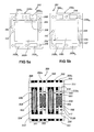
figures 5a, 5b show front-views of two different embodiments of a component of the electrochemical generator offigure 4 ; - figure 6 shows a side-view of a portion of a third embodiment of a membrane electrochemical generator according to the invention;
-
figures 7a, 7b show front-views of a component of the electrochemical generator of figure 6; -
figures 8a, 8b show front-views of a further component of the electrochemical generator of figure 6; -
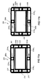
figures 9a, 9b show front-views of a different embodiment of the component shown infigures 8a and 8b ; -
figures 10a, 10b show front-views of a different embodiment of the component shown infigures 7a and 7b ; -
figures 11a, 11b show front-views of a different embodiment of the component shown infigures 8a and 8b ; and -
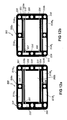
figures 12a, 12b show front-views of a different embodiment of the component shown infigures 9a and 9b . -
Figure 1 shows a first embodiment of a membrane electrochemical generator according to the invention. Theelectrochemical generator 1 comprises a multiplicity ofreaction cells 2 mutually connected in series and assembled according to a filter-press type configuration. - More in detail, each
reaction cell 2 is delimited by a pair of conductivebipolar plates 3, with planar faces, among which are comprised, proceeding outwards, the proton-exchange membrane 4; a pair of porous electrodes 5; a pair ofcatalytic layers 6 deposited at the interface betweenmembrane 4 and each of the porous electrodes 5; a pair of current collectors/distributors 7, realised by means of a reticulated metallic element of the type described inUS Patent 5,482,792 , electrically connecting the conductivebipolar plates 3 to the porous electrodes 5 while simultaneously distributing the gaseous reactants; a sealinggasket pair anodic sealing gasket 8a and acathodic sealing gasket 8b. Theanodic sealing gasket 8a is directed to seal the periphery of theanodic chamber 9 of thereaction cell 2 in order to avoid the leakage of fuel (hydrogen in particular), while thecathodic sealing gasket 8b is directed to seal the periphery of thecathodic chamber 10 of thereaction cell 2 in order to avoid the leakage of oxidant (air in particular). The anodic andcathodic sealing gaskets distributors 7. - As shown in
figure 2 , the conductivebipolar plates 3 have a substantially rectangular shape and each of them presents aperimetrical portion 11 provided with: first and secondupper openings lower openings side openings 16 for the passage of a cooling fluid, in particular liquid water. Theperimetrical portion 11 is also provided with a multiplicity ofholes 17 for the housing of tie-rods by means of which the tightening of theelectrochemical generator 1 is accomplished. - During the assemblage of the
electrochemical generator 1, the coupling between the first and the secondupper openings bipolar plates 3 determines the formation of two upperlongitudinal ducts 18 while the coupling between the first and the secondlower openings bipolar plates 3 determines the formation of two lowerlongitudinal ducts 19. The two upperlongitudinal ducts 18, only one of which is shown infigure 1 , define the feeding manifolds of the gaseous reactants while the two lowerlongitudinal ducts 19, only one of which is shown infigure 1 , define the discharge manifolds of the reaction products mixed with the optional residual reactants. Alternatively, the lowerlongitudinal ducts 19 can be employed as feeding manifolds, and the upperlongitudinal ducts 18 as discharge manifolds. It is also possible to feed one of the two gaseous reactants through one of the upperlongitudinal ducts 18, using the corresponding lowerlongitudinal duct 19 for the discharge and feeding the other gaseous reactant through the other lowerlongitudinal duct 19 using the corresponding upperlongitudinal duct 18 for the discharge. - Moreover, the coupling between the
side openings 16 of all the conductivebipolar plates 3 determines the formation of side ducts, not shown infigure 1 , for the passage of the liquid water. - Each conductive
bipolar plate 3 is also provided with a multiplicity of fluid injection calibratedholes 20, all having the same diameter (for instance comprised between 0,2 mm ÷ 1 mm), through which the liquid water flowing in the side ducts of theelectrochemical generator 1 is injected into thereaction cells 2, as will be better explained hereafter. The fluid injection calibratedholes 20 are mutually aligned in order to ensure a homogeneous distribution of the liquid water and are placed below the first and secondupper openings - As shown in
figures 3a, 3b ,3c the anodic andcathodic sealing gaskets reaction cell 2 have a substantially rectangular shape and present respective first and secondupper openings lower openings respective side openings - More in detail, the first
upper openings 8a1 (through which the fuel passes) and the secondlower openings 8a4 of theanodic gasket 8a are connected to theanodic chamber 9 through, respectively,distribution channels 21 a anddischarge channels 21 b, obtained within the thickness of the same anodic sealing gasket (figure 3a ). In their turn, the secondupper openings 8b2 (through which the oxidant passes) and the firstlower openings 8b3 of thecathodic sealing gasket 8b are connected to thecathodic chamber 10 respectively through thedistribution channels 23a and the discharge channels 23b, obtained within the thickness of the same cathodic sealing gasket (figure 3b ). The distributing anddischarge channels reaction cell 2 the gaseous reactants and the reaction products, the latter mixed with the optional residual reactants, in a uniform fashion. Theanodic sealing gasket 8a is also provided withfluid collection channels 22 connected with theside openings 8a5. Optionally, thefluid collection channels 22 can also be connected to thedistribution channels 21 a (figure 3c ). - In a filter-press configuration, the first and the second
upper openings cathodic sealing gaskets upper openings bipolar plates 3 the two upperlongitudinal ducts 18; the first and the secondlower openings cathodic sealing gaskets lower openings bipolar plates 3 the two lowerlongitudinal ducts 19; theside openings cathodic sealing gaskets side openings 16 of the conductivebipolar plates 3 the side ducts for the liquid water feed. - Moreover, in a filter-press configuration, the
fluid collection channels 22 with which theanodic sealing gasket 8a is provided are placed in correspondence of the fluid injection calibratedholes 20 which in their turn are placed each in correspondence of adistribution channel 23a of thecathodic sealing gasket 8b. - The anodic and
cathodic sealing gaskets holes 24 for housing the tie-rods by means of which the tightening of theelectrochemical generator 1 is accomplished. - In its turn, the
electrochemical generator 1 is delimited by two conductive terminal plates 25 (figure 1 ), one of which is provided with nozzles, not shown infigure 1 , for the hydraulic connection of the upper and lowerlongitudinal ducts conductive terminal plates 25 are provided with appropriate holes (also not shown infigure 1 ) for housing the tie-rods. - Operatively, the flow of liquid water supplied through the side ducts of the
electrochemical generator 1 flows in thefluid collection channels 22 of theanodic sealing gaskets 8a and from here, through the fluid injection calibratedholes 20, is injected in the cathodic reactive streams entering theadjacent reaction cells 2. - As an alternative, if the
anodic sealing gaskets 8a have a structure equivalent to the one shown infigure 3b and thecathodic 8a have a structure equivalent to the one shown insealing gaskets 8bfigure 3a the stream of liquid water flows in thefluid collection channels 22, in this case obtained within thecathodic sealing gaskets 8b, and from here, through the fluid injection calibratedholes 20, is injected in the anodic reactive streams entering theadjacent reaction cells 2. - In both cases, the thermal management of the
electrochemical generator 1 and the humidification of themembrane 4 are performed by the evaporation of the liquid water flow across the reticulated metallic element which realises the current collector/distributor 7. - In
figure 4 , wherein the equivalent parts to those already illustrated making reference tofigures 1 ,2 and3 have been provided with the same reference numerals, a second embodiment of membrane electrochemical generator according to the invention is shown. Theelectrochemical generator 100 is entirely similar to theelectrochemical generator 1 except that it comprises a multiplicity ofadditional cells 101, interposed between thereaction cells 2 in a 1:1 ratio. - Making reference to
figure 5a , theadditional cells 101 have a substantially rectangular shape and dimensions equivalent to those of thereaction cells 2 and each comprises aperimetrical portion 102a, acting as the separating surface for the two gaseous reactants and a hollow central portion 102b to realise the seat of the current collector/distributor 7. Theperimetrical portion 102a is provided with first and second upper openings 103a1, 103a2, first and second lower openings 103b1, 103b2 andside openings 104 placed in correspondence of the first and second upper openings 103a1, 103a2. - In a filter-press configuration, the first and the second upper openings 103a1, 103a2 of the
additional cells 101 form, in conjunction with the first and the secondupper openings cathodic sealing gaskets figure 3b , and with the first and the secondupper openings bipolar plates 3, the two upperlongitudinal ducts 18; the first and the second lower openings 103b1, 103b2 of theadditional cells 101 form, in conjunction with the first and the secondlower openings cathodic sealing gaskets lower openings bipolar plates 3, the two lowerlongitudinal ducts 19. In their turn, theside openings 104 of theadditional cells 101 form, in conjunction with theside openings cathodic sealing gaskets side openings 16 of the conductivebipolar plates 3 the side feeding ducts of the liquid water. Theperimetrical portion 102a is also provided with a multiplicity ofholes 105 for housing the tie-rods. - Furthermore, on both faces of the
perimetrical portion 102a afluid collection channel 106 is present, connected to theside openings 104 and positioned below the first and second upper openings 103a1, 103a2. In a filter-press configuration, thefluid collection channel 106 is in correspondence of the fluid injection calibratedholes 20 of the conductivebipolar plates 3. - Operatively, the stream of liquid water supplied through the side ducts of the
electrochemical generator 100 flows in thefluid collection channel 106 and from here, through the fluid injection calibratedholes 20, is injected in the reactant streams entering theadjacent reaction cells 2. - As an alternative, the
fluid collection channel 106 may be formed by twoside portions 107, 108, connected with theside openings 104, the latter being obtained in correspondence of the first and second lower openings 103b1, 103b2 (figure 5b ). - In this case, the stream of liquid water, prior to reaching the fluid injection calibrated
holes 20 and being injected into thereaction cells 2, enters the twoside portions 107, 108 of thefluid collection channel 106 to subsequently cross the whole surface of the current collector/distributor 7 of theadditional cell 101 pre-heating counter-currently or concurrently with respect to at least one of the reactant flows entering thereaction cells 2. In this way, theadditional cells 101 acts as cooling cells of theelectrochemical generator 100. - Figure 6 shows a cross-section of a third embodiment, according to the invention, of a membrane electrochemical generator. The
electrochemical generator 200, only a portion of which is shown in figure 6, is formed by a multiplicity ofreaction cells 201 and ofadditional cells 202 mutually connected in series and assembled according to a filter-press type configuration; eachadditional cell 202 being interposed between a pair ofreaction cells 201. - More in detail, each
reaction cell 201 is delimited by a pair of flat-face conductivebipolar plates 203 among which are comprised, proceeding outwards, a proton-exchange membrane 204; a pair ofporous electrodes 205; a pair of current collector/distributors 206 electrically connecting the conductivebipolar plates 203 to theporous electrodes 205; a pair of sealinggaskets 207 directed to seal the periphery of thereaction cell 201 in order to avoid the leakage of the gaseous reactants. - The conductive
bipolar plates 203, shown infigures 7a, 7b , have a substantially rectangular shape and a typical thickness of 0,1÷0,4 mm. They present aperimetrical portion 208 provided with first and secondupper openings side openings 209. Theperimetrical portion 208 is also provided with a multiplicity ofholes 210 for housing the tie-rods by means of which the tightening of theelectrochemical generator 200 is achieved. - During the assemblage of the
electrochemical generator 200, the coupling between the first and the secondupper openings bipolar plates 203 determines the formation of two upperlongitudinal ducts 211 while the coupling between the first and the second lower openings 208b1, 208b2 of all the conductivebipolar plates 203 determines the formation of two lowerlongitudinal ducts 212. The two upperlongitudinal ducts 211, only one of which is shown in figure 6, define the feeding manifolds of the gaseous reactants (fuel and oxidant) while the two lowerlongitudinal ducts 212, only one of which is shown in figure 6, define the discharge manifolds of the reaction products mixed with the optional residual reactants. As an alternative, the lowerlongitudinal ducts 212 may be employed as feeding manifolds, and the upperlongitudinal ducts 211 as discharge manifolds. It is also possible to feed one of the two gaseous reactants through one of the upperlongitudinal ducts 211, using the correspondent lowerlongitudinal duct 212 for the discharge and feeding the other gaseous reactant through the other lowerlongitudinal duct 212 using the correspondent upperlongitudinal duct 211 for the discharge. - Moreover, the coupling between the
side openings 209 of all the conductivebipolar plates 203 determines the formation of side ducts, not shown in figure 6, for the passage of liquid water. - As shown in
figure 7b , the sealinggaskets 207 are laid on just one face of each conductivebipolar plate 203 by (injection or compression) moulding, mechanical anchoring or gluing. They realise the seat of the current collector/distributors 206 besides delimiting the active area of thereaction cells 201. - In particular, the sealing
gaskets 207 are obtained with a soft material, for instance silicone, elastomer, etc, and present a final thickness which can range from some tenth of a millimetre to a few millimetres. - Each conductive
bipolar plate 203 is also provided with a multiplicity of upper calibratedholes 213a and of a multiplicity of lower calibrated holes 213b of diameter comprised between 0,1 mum ÷ 5 mm. Through the multiplicity of upper calibratedholes 213a the gaseous reactants coming from the adjacentadditional cell 202 flow, while through the multiplicity of lower calibrated holes 213b the reaction products and the residual reactants exit thereaction cell 201, as will be explained more in detail hereafter. The upper calibratedholes 213a are mutually aligned in order to ensure a homogeneous distribution of the gaseous reactants and are placed below the first and secondupper openings gasket 207 by about 1 mm for better exploiting the active area of thereaction cell 201. - Furthermore, each conductive
bipolar plate 203 is provided with a multiplicity of fluid injection calibratedholes 230, all having the same diameter (for example comprised between 0,2 mm ÷ 1mm), through which the liquid water coming from the adjacentadditional cell 202 is injected into thereaction cell 201. The fluid injection calibratedholes 230 are mutually aligned in order to ensure a homogeneous distribution of liquid water and are placed below the upper calibratedholes 213a. - Making now reference to
figures 8a, 8b , eachadditional cell 202 has a substantially rectangular shape and dimensions equivalent to those of thereaction cell 201. Eachadditional cell 202 comprises a rigidperimetrical portion 202a, made of plastic or metal, acting as the separating surface for the two gaseous reactants and a hollowcentral portion 202b to realise the seat of the current collector/distributor 206. The rigidperimetrical portion 202a is provided with first and secondupper openings lower openings side openings 215. In a filter-press configuration, the first and the secondupper openings additional cells 202 form, in conjunction with the first and secondupper openings bipolar plates 203, the two upperlongitudinal ducts 211, while the first and the secondlower openings additional cells 202 form, in conjunction with the first and second lower openings 208b1, 208b2 of the conductivebipolar plates 203, the two lowerlongitudinal ducts 212. In their turn, theside openings 215 of theadditional cells 202 form, in conjunction with theside openings 209 of the conductivebipolar plates 203 the feeding ducts of the liquid water. The rigidperimetrical portion 202a is also provided with a multiplicity ofholes 216 for housing the tie-rods. - Moreover, each
additional cell 202 comprisesgaskets 217 which are laid on both faces of the rigidperimetrical portion 202a so that they define on each face of the perimetrical portion itself: a collection channel of thegaseous reactants 218a placed below the first and secondupper openings residual reactants 218b placed above the first and secondlower openings feeding channel 219 to connect one of the twoupper openings gaseous reactants 218a; adischarge channel 220 to connect the collection channel of the reaction products and of theresidual reactants 218b to one of thelower openings fluid collection channel 221 placed below the collection channel of thegaseous reactants 218a and connecting theside openings 209. In a filter-press configuration, the collection channel of thegaseous reactants 218a is placed in correspondence of the upper calibratedholes 213a, the collection channel of the reaction products and of theresidual reactants 218b is placed in correspondence of the lower calibrated holes 213b while thefluid collection channel 221 is placed in correspondence of the fluid injection calibratedholes 230. Thegaskets 217 seal the collection channel of thegaseous reactants 218a, the collection channel of the reaction products and of theresidual reactants 218b and thefluid collection channel 221 so as to hinder the passage of the gaseous reactants, of the reaction products and of the residual reactants and of liquid water inside theadditional cell 202. - Moreover, the
gaskets 217 are made of a soft material (silicone, elastomer etc.) compatible with the tightening/assemblage loads imposed by the sealinggaskets 207 of thereaction cell 201 and are laid on the rigidperimetrical portion 202a by (injection or compression) moulding, mechanical anchoring or gluing. - The
electrochemical generator 200 operates as follows. The gaseous reactants (fuel and oxidant) supplied to theelectrochemical generator 200 through the upperlongitudinal ducts 211 flow in the collection channels of thegaseous reactants 218a through the feedingchannels 219. From here, the gaseous reactants, being unable to flow withinadditional cells 202 since the collection channels of the gaseous reactants 218 are sealed bygaskets 217, pass through the multiplicity of upper calibratedholes 213a placed on the conductivebipolar plates 203 of theadjacent reaction cells 201. In this way, the gaseous reactants reach the active are of thereaction cells 201 where the effective reaction takes place. - In their turn, the reaction products and the residual reactants generated in the
reaction cells 201 pass through the multiplicity of lower calibrated holes 213b placed on the conductivebipolar plates 203 of the same reaction cells reaching the collection channels of thedischarge products 218b of the adjacentadditional cells 202. From here, they exit theelectrochemical generator 200 through thedischarge channels 220. - Furthermore, according to the present invention, the stream of liquid water supplied through the side ducts of the
electrochemical generator 200 flows in thefluid collection channels 221 and from here, through the fluid injection calibratedholes 230, is injected into the reactant streams entering theadjacent reaction cells 201 providing for the humidification ofmembrane 204 and for the thermal management of theelectrochemical generator 200. - As an alternative to the
fluid collection channel 221, theadditional cell 202 may comprise two lateral fluid collection channels (222, 223) connected to theside openings 215 and placed below the collection channel of thedischarge products 218b (figures 9a, 9b ). - In this case, the flow of liquid water, prior to reaching the fluid injection calibrated
holes 230 and being injected into thereaction cells 201, enters through the two lateralfluid collection channels distributor 206 of theadditional cell 202 pre-heating counter-currently or concurrently with respect to at least one of the reactant flows entering thereaction cells 201. In this way theadditional cells 202 act as cooling cells of theelectrochemical generator 200. - Moreover, as shown in
figures 10a, 10b , the fluid injection calibratedholes 230 of each conductivebipolar plate 203 may be placed above (rather than below) the upper calibratedholes 213a. In this case thefluid collection channel 221 is placed above the collection channel of thegaseous reactants 218a (figures 11a, 11b ). - As an alternative, besides the
fluid collection channel 221, theadditional cell 202 may comprise a first and a secondlateral channel discharge products 218b, and a third and a fourthlateral channel gaseous reactants 218a (figures 12a, 12b ). - In this case, the flow of liquid water, prior to reaching the fluid injection calibrated
holes 230 and being injected into thereaction cells 201, enters the first and secondlateral channel lateral channel distributor 206 of theadditional cell 202 so that it is pre-heated counter-currently or concurrently with respect to at least one of the reactant streams supplied to thereaction cells 201. - The advantages obtainable with the above described electrochemical generators are the following.
- First, the fluid injection calibrated
holes reaction cells electrochemical generators exchange membranes - Moreover, the liquid water flow pre-heating achieved by the use of the additional cells shown in
figures 5b ,9a ,9b and12a, 12b amplifies the above disclosed advantages since it further enhances the liquid water evaporative mechanism allowing a further reduction of the time for reaching steady-state conditions at the start-up of theelectrochemical generators - It is finally evident that modifications and variations can be made to the described electrochemical generators, without departing from the domain of the present invention.
Claims (20)
- Membrane electrochemical generator (1, 100, 200) fed with gaseous reactants and comprising a multiplicity of reaction cells (2, 201) being delimited by conductive bipolar plates (3, 203) among which is comprised a proton-exchange membrane (4, 204), characterised in that said conductive bipolar plates (3, 203) comprise a multiplicity of fluid injection calibrated holes (20, 230) for the injection of a calibrated flow of a cooling fluid inside said reaction cells (2, 201), a multiplicity of additional cells (101), each of the additional cells (101) being interposed between a pair of reaction cells (2), realizing a seat for a respective electrically conductive reticulated element (7) and comprising a perimetrical portion (102a) in which are obtained:- side openings (104) for the passage of said cooling fluid ;- at least one fluid collection channel (106) connected to said side openings (104) and suited to collect said cooling fluid ;- feed openings (103a1, 103a2) for the passage of said gaseous reactants;- discharge openings (103b1, 103b2) for discharging the reaction products and residual reactants,wherein said fluid collection channel (106) is placed below said feed openings (103a1, 103a2), and said fluid collection channel (106) is superposed to said fluid injection calibrated holes (20) of said conductive bipolar plates (3).
- Generator according to claim 1, characterised in that each of said reaction cells (2, 201) is formed by an anodic chamber (9) and a cathodic chamber (10) separated by said membrane (4, 204), said anodic chamber (9) and said cathodic chamber (10) each comprising an electrically conductive reticulated element (7, 206) at whose interior said calibrated flow of said cooling fluid partially evaporates simultaneously providing for the humidification of said gaseous reactants and for the thermal management of said membrane electrochemical generator (1,100, 200).
- Generator according to claim 1 or 2, characterised in that said fluid injection calibrated holes (20, 230) are mutually aligned and placed in correspondence of feed openings (12, 13, 208a1, 208a2) for feeding said gaseous reactants and of side openings (16, 209) for feeding said cooling fluid (12, 13, 208a1, 208a2) and said side openings (16, 209) being obtained in a perimetrical portion (11, 208) of said conductive bipolar plates (3, 203).
- Generator according to anyone of claims 1-3, characterised in that said fluid injection calibrated holes (20, 230) have the same diameter comprised between 0.2 mm -1mm.
- Generator according to anyone of the previous claims, characterized in that a pair of gaskets (8a, 8b), are interposed between a pair of said conductive bipolar plates delimiting said reaction cell (2), said sealing gaskets (8a, 8b) each realizing a seat for a respective electrically conductive reticulated element (7) and comprising:- respective feed openings (8a1, 8a2, 8b1, 8b2) for the passage of said gaseous reactants;- respective side openings (8a5; 8b5) for the passage of said cooling fluid;- respective distribution channels (21 a, 23a) to connect said respective feed openings (8a1, 8a2, 8b1, 8b2) to said respective electrically conducting reticulated element (7).
- Generator according to anyone of the previous claims, characterised in that said fluid collection channel (106) is formed by a first and a second side portion (107,108) placed above said discharge openings (103b1, 103b2).
- Generator according to claim 6, characterised in that said cooling fluid, prior to reaching said fluid injection holes (20), crosses the whole surface of said respective electrically conductive reticulated element (7) pre-heating counter-currently or concurrently with respect to at least one gaseous flow entering said reaction cells (2).
- Membrane electrochemical generator (200) fed with gaseous reactants and comprising a multiplicity of reaction cells (201) being delimited by conductive bipolar plates (3, 203) among which is comprised a proton-exchange membrane (4, 204), wherein said conductive bipolar plates (203) comprise a multiplicity of fluid injection calibrated holes (230) for the injection of a calibrated flow of a cooling fluid inside said reaction cells (201) a multiplicity of first calibrated holes (213a) for the passage of said gaseous reactants and a multiplicity of second calibrated holes (213b) for the discharge of reaction products and of optional residual reactants, said multiplicity of fluid injection calibrated holes (20, 230) are placed in correspondence of said multiplicity of first calibrated holes (213a); said membrane electrochemical generator further comprising a multiplicity of additional cells (202), each of the additional cells (201) being interposed between a pair of reaction cells (201), said additional cells comprising a rigid perimetrical portion (202a) and a hollow central portion (202b), said rigid perimetrical portion (202a) acting as a separating surface for said gaseous reactants and said hollow central portion (202b) realizing a seat for a respective electrically conductive reticulated element (206).
- Generator according to claim 8, characterised in that said first calibrated holes (213a) are mutually aligned and placed in correspondence of said feed openings (208a1, 208a2) of said conductive bipolar plates (203) and that said second calibrated holes (213b) are mutually aligned and placed in correspondence of discharge openings (208b1, 208b2) obtained on said perimetrical portion (208) of said conductive bipolar plates (203).
- Generator according to claim 8 or 9, characterised in that said reaction cells (201) comprise a sealing gasket (207) covering only one face of said perimetrical M/44167-EP (10585.0024-00155, case 201 EP) portion (208) of said conductive bipolar plates (203), said sealing gasket (207) realising a seat for a respective electrically conductive reticulated element (206).
- Generator according to anyone of claims 8 to 10, characterised in that said rigid perimetrical portion (202a) is provided with feed openings (214a1, 214a2) for feeding said gaseous reactants, of discharge openings (214b1, 214b2) for discharging the reaction products and the residual reactants and of side openings (215) for the passage of said cooling fluid.
- Generator according to anyone of claims 8 to 11, characterised in that said rigid perimetrical portion (202a) is covered on each face by a gasket (217), said gasket (217) defining on each face of said rigid perimetrical portion (202a) a zone of collection of the gaseous reactants (218a) placed in correspondence of said feed openings (214a1, 214a2) of said rigid perimetrical portion (202a), a zone of collection of the reaction products and of the residual reactants (218b) placed in correspondence of said discharge openings (214b1, 214b2) of said rigid perimetrical portion (202a), a feed channel (219) to connect one of said feed openings (214a1, 214a2) to said zone of collection of the gaseous reactants (218a), a discharge channel (220) to connect said zone of collection of the reaction products and of the residual reactants (218b) to one of said discharge openings (214b1, 214b2).
- Generator according to claim 12, characterised in that said gasket (117) seals said zone of collection of the gaseous reactants (218a) and said zone of collection of the reaction products and of the residual reactants (218b) so as to hinder the passage of said gaseous reactants and of said reaction products and optional residual reactants within said additional cell (202).
- Generator according to claim 12 or 13, characterised in that in a filter- press configuration said zone of collection of the gaseous reactants (218a) is superposed to said first calibrated holes (213a) and said zone of collection of the reaction products and of the residual reactants (218b) is superposed to said second calibrated holes (213b).
- Generator according to anyone of claims 12 to 14, characterised in that said fluid injection calibrated holes (230) are placed below said first calibrated holes (213a) and that said gasket (217) defines on each face of said rigid perimetrical portion (202a) a fluid collection channel (221) placed below said feed openings (214a1, 214a2) of said additional cells (202).
- Generator according to anyone of claims 12 to 14, characterised in that said fluid injection calibrated holes (230) are interposed between said feed openings (208a1, 208a2) of said bipolar plates (203) and said first calibrated holes (113a, 113b) and that said gasket (217) defines on each face of said rigid perimetrical portion (202a) a fluid collection channel (221) interposed between said feed openings (214a1, 214a2) of said additional cell (202) and said zone of collection of the gaseous reactants (118a).
- Generator according to claim 15 or 16, characterised in that in a filter-press configuration said fluid collection channel (221) is superposed to said fluid injection calibrated holes (230).
- Generator according to anyone of claims 12 to 14, characterised in that said additional cells (202) comprise a first and a second fluid collection lateral channel (222, 223) connected to said side openings (215) of said additional cells (202) and placed above said discharge openings (214b1, 214b2) of said additional cells (202) and that said cooling fluid, prior to reaching said fluid injection holes (230) passes through said first and second fluid collection lateral channel (222, 223) to cross subsequently the whole surface of said respective electrically conductive reticulated element (206) pre-heating counter-currently or concurrently with respect to at least one gaseous flow entering said reaction cells (201).
- Generator according to anyone of claims 12 to 14, characterised in that said additional cells (202) comprise:- a first and a second fluid collection lateral channel (224, 225) connected to said side openings (215) of said additional cells (202) and placed above said discharge openings (214b1, 214b2) of said additional cells (202);- a third and a fourth fluid collection lateral channel (226, 227) connected to said side openings (215) of said additional cells (202) and placed below said feed openings (214a1, 214a2) of said additional cells (202);- a fluid collection channel (221) interposed between said feed openings (214a1, 214a2) of said additional cells (202) and said zone of collection of the gaseous reactants (218a) and connected to said side openings (215) of said additional cells (202);and that said cooling fluid, prior to reaching said fluid injection holes (230) enters through said first and second fluid collection lateral channel (224, 225) to subsequently cross the whole surface of said respective electrically conductive reticulated element (206), pre-heating counter-currently or concurrently with respect to at least one gaseous flow entering said reaction cells (201), said cooling fluid subsequently exiting from said third and fourth fluid collection lateral channel (226, 227);
and that in a filter-press configuration said fluid collection channel (221) is superposed to said fluid injection calibrated holes (230). - Generator according to anyone of the previous claims, characterised in that said cooling fluid is liquid water.
Applications Claiming Priority (3)
| Application Number | Priority Date | Filing Date | Title |
|---|---|---|---|
| IT2002MI001338A ITMI20021338A1 (en) | 2002-06-17 | 2002-06-17 | MEMBRANE ELECTROCHEMICAL GENERATOR WITH DIRECT INJECTION OF LIQUID WATER IN GASEOUS AGENTS |
| ITMI20021338 | 2002-06-17 | ||
| PCT/EP2003/006327 WO2003107465A1 (en) | 2002-06-17 | 2003-06-16 | Fuel cell with evaporative cooling and humidification |
Publications (2)
| Publication Number | Publication Date |
|---|---|
| EP1520314A1 EP1520314A1 (en) | 2005-04-06 |
| EP1520314B1 true EP1520314B1 (en) | 2015-09-02 |
Family
ID=29727281
Family Applications (1)
| Application Number | Title | Priority Date | Filing Date |
|---|---|---|---|
| EP03735632.6A Expired - Lifetime EP1520314B1 (en) | 2002-06-17 | 2003-06-16 | Fuel cell with evaporative cooling and humidification |
Country Status (11)
| Country | Link |
|---|---|
| US (1) | US7666536B2 (en) |
| EP (1) | EP1520314B1 (en) |
| JP (1) | JP4954472B2 (en) |
| KR (1) | KR101061395B1 (en) |
| CN (1) | CN1663068A (en) |
| AU (1) | AU2003237948A1 (en) |
| BR (1) | BR0311888A (en) |
| CA (1) | CA2488652C (en) |
| ES (1) | ES2552229T3 (en) |
| IT (1) | ITMI20021338A1 (en) |
| WO (1) | WO2003107465A1 (en) |
Families Citing this family (4)
| Publication number | Priority date | Publication date | Assignee | Title |
|---|---|---|---|---|
| GB2409763B (en) | 2003-12-31 | 2007-01-17 | Intelligent Energy Ltd | Water management in fuel cells |
| KR100737017B1 (en) * | 2005-11-15 | 2007-07-09 | 현대자동차주식회사 | Fuel Cell Stack Humidifier |
| US8889314B2 (en) * | 2009-01-13 | 2014-11-18 | GM Global Technology Operations LLC | Bipolar plate for a fuel cell stack |
| DE102012011863A1 (en) * | 2012-06-14 | 2013-03-07 | Daimler Ag | Fuel cell system for vehicle, has flow channels for flowing humidifying mediums that are formed in separator plates at different locations, and moistening device that is set to moisten electrolyte membrane with humidifying mediums |
Family Cites Families (9)
| Publication number | Priority date | Publication date | Assignee | Title |
|---|---|---|---|---|
| IT1270878B (en) * | 1993-04-30 | 1997-05-13 | Permelec Spa Nora | IMPROVED ELECTROCHEMISTRY CELL USING ION EXCHANGE MEMBRANES AND METAL BIPOLAR PLATES |
| JPH07509807A (en) | 1993-06-02 | 1995-10-26 | フィリップス エレクトロニクス ネムローゼ フェンノートシャップ | Flat panel display with electron transport duct and segmented filament |
| US5998054A (en) * | 1997-07-23 | 1999-12-07 | Plug Power, L.L.C. | Fuel cell membrane hydration and fluid metering |
| IT1312198B1 (en) | 1999-04-21 | 2002-04-09 | De Nora Spa | COOLED FUEL CELL BY DIRECT INJECTION OF AQUALIQUIDA |
| ITMI991090A1 (en) * | 1999-05-18 | 2000-11-18 | De Nora Spa | HUMIDIFYING DEVICE FOR POLYMER MEMBRANE FUEL CELLS |
| JP4812920B2 (en) * | 2000-02-22 | 2011-11-09 | 本田技研工業株式会社 | Fuel cell stack |
| JP4623795B2 (en) * | 2000-03-16 | 2011-02-02 | 本田技研工業株式会社 | Fuel cell stack |
| US6689500B2 (en) * | 2001-03-29 | 2004-02-10 | Power Plug, Inc. | Cooling a fuel cell stack |
| JP4085652B2 (en) * | 2001-08-21 | 2008-05-14 | 株式会社エクォス・リサーチ | Fuel cell |
-
2002
- 2002-06-17 IT IT2002MI001338A patent/ITMI20021338A1/en unknown
-
2003
- 2003-06-16 CA CA2488652A patent/CA2488652C/en not_active Expired - Lifetime
- 2003-06-16 CN CN038141515A patent/CN1663068A/en active Pending
- 2003-06-16 BR BR0311888-6A patent/BR0311888A/en not_active Application Discontinuation
- 2003-06-16 JP JP2004514170A patent/JP4954472B2/en not_active Expired - Fee Related
- 2003-06-16 US US10/517,982 patent/US7666536B2/en not_active Expired - Lifetime
- 2003-06-16 ES ES03735632.6T patent/ES2552229T3/en not_active Expired - Lifetime
- 2003-06-16 WO PCT/EP2003/006327 patent/WO2003107465A1/en not_active Ceased
- 2003-06-16 EP EP03735632.6A patent/EP1520314B1/en not_active Expired - Lifetime
- 2003-06-16 KR KR1020047020326A patent/KR101061395B1/en not_active Expired - Lifetime
- 2003-06-16 AU AU2003237948A patent/AU2003237948A1/en not_active Abandoned
Also Published As
| Publication number | Publication date |
|---|---|
| US20070196710A1 (en) | 2007-08-23 |
| KR20050034647A (en) | 2005-04-14 |
| ITMI20021338A1 (en) | 2003-12-17 |
| JP2005530322A (en) | 2005-10-06 |
| CA2488652C (en) | 2011-10-25 |
| BR0311888A (en) | 2005-04-05 |
| WO2003107465A1 (en) | 2003-12-24 |
| EP1520314A1 (en) | 2005-04-06 |
| CN1663068A (en) | 2005-08-31 |
| KR101061395B1 (en) | 2011-09-05 |
| CA2488652A1 (en) | 2003-12-24 |
| AU2003237948A1 (en) | 2003-12-31 |
| ES2552229T3 (en) | 2015-11-26 |
| US7666536B2 (en) | 2010-02-23 |
| JP4954472B2 (en) | 2012-06-13 |
Similar Documents
| Publication | Publication Date | Title |
|---|---|---|
| US7285352B2 (en) | Separator for fuel cell and fuel cell therewith | |
| EP0959511B1 (en) | Separator for a unit cell of a fuel cell, and fuel cell using the same | |
| CA2408538C (en) | Fuel cell assembly with heater wire provided on a grid frame of an electrolyte layer | |
| US20020006539A1 (en) | Fuel cell assembly | |
| JPH10510390A (en) | PEM fuel cell | |
| WO2001059864A1 (en) | Polymer electrolyte fuel cell | |
| JP2011198776A (en) | Membrane electrochemical generator | |
| US20090123784A1 (en) | Fuel cell module | |
| JP2000277132A (en) | Fuel cell | |
| JPH0950819A (en) | Solid polymer electrolyte fuel cell | |
| JP3858016B2 (en) | Fuel cell and fuel cell separator | |
| CA2488652C (en) | Membrane electrochemical generator | |
| EP1952471B1 (en) | Pem fuel cell with charging chamber | |
| JP4642975B2 (en) | Polymer electrolyte fuel cell system | |
| US3445294A (en) | Electrode backing plate for fuel cells | |
| JPH1167260A (en) | Fuel cell device | |
| EP1547179B1 (en) | Membrane electrochemical generator | |
| CN1326279C (en) | polymer electrolyte fuel cell | |
| JP2004207082A (en) | Fuel cell and fuel cell separator | |
| CA2351871A1 (en) | Liquid reactant flow field plates for liquid feed fuel cells |
Legal Events
| Date | Code | Title | Description |
|---|---|---|---|
| PUAI | Public reference made under article 153(3) epc to a published international application that has entered the european phase |
Free format text: ORIGINAL CODE: 0009012 |
|
| 17P | Request for examination filed |
Effective date: 20050114 |
|
| AK | Designated contracting states |
Kind code of ref document: A1 Designated state(s): AT BE BG CH CY CZ DE DK EE ES FI FR GB GR HU IE IT LI LU MC NL PT RO SE SI SK TR |
|
| AX | Request for extension of the european patent |
Extension state: AL LT LV MK |
|
| DAX | Request for extension of the european patent (deleted) | ||
| 17Q | First examination report despatched |
Effective date: 20091106 |
|
| GRAP | Despatch of communication of intention to grant a patent |
Free format text: ORIGINAL CODE: EPIDOSNIGR1 |
|
| INTG | Intention to grant announced |
Effective date: 20150330 |
|
| GRAS | Grant fee paid |
Free format text: ORIGINAL CODE: EPIDOSNIGR3 |
|
| GRAA | (expected) grant |
Free format text: ORIGINAL CODE: 0009210 |
|
| AK | Designated contracting states |
Kind code of ref document: B1 Designated state(s): AT BE BG CH CY CZ DE DK EE ES FI FR GB GR HU IE IT LI LU MC NL PT RO SE SI SK TR |
|
| REG | Reference to a national code |
Ref country code: GB Ref legal event code: FG4D |
|
| REG | Reference to a national code |
Ref country code: DE Ref legal event code: R081 Ref document number: 60347987 Country of ref document: DE Owner name: NUVERA FUEL CELLS EUROPE S.R.L., IT Free format text: FORMER OWNER: NUVERA FUEL CELLS EUROPE S.R.L., MAILAND/MILANO, IT |
|
| REG | Reference to a national code |
Ref country code: AT Ref legal event code: REF Ref document number: 747116 Country of ref document: AT Kind code of ref document: T Effective date: 20150915 Ref country code: CH Ref legal event code: EP |
|
| REG | Reference to a national code |
Ref country code: IE Ref legal event code: FG4D |
|
| REG | Reference to a national code |
Ref country code: DE Ref legal event code: R096 Ref document number: 60347987 Country of ref document: DE |
|
| REG | Reference to a national code |
Ref country code: ES Ref legal event code: FG2A Ref document number: 2552229 Country of ref document: ES Kind code of ref document: T3 Effective date: 20151126 |
|
| REG | Reference to a national code |
Ref country code: DE Ref legal event code: R081 Ref document number: 60347987 Country of ref document: DE Owner name: NUVERA FUEL CELLS EUROPE S.R.L., IT Free format text: FORMER OWNER: NUVERA FUEL CELLS EUROPE S.R.L., MAILAND/MILANO, IT |
|
| RAP2 | Party data changed (patent owner data changed or rights of a patent transferred) |
Owner name: NUVERA FUEL CELLS EUROPE S.R.L. |
|
| REG | Reference to a national code |
Ref country code: AT Ref legal event code: MK05 Ref document number: 747116 Country of ref document: AT Kind code of ref document: T Effective date: 20150902 |
|
| PG25 | Lapsed in a contracting state [announced via postgrant information from national office to epo] |
Ref country code: FI Free format text: LAPSE BECAUSE OF FAILURE TO SUBMIT A TRANSLATION OF THE DESCRIPTION OR TO PAY THE FEE WITHIN THE PRESCRIBED TIME-LIMIT Effective date: 20150902 Ref country code: GR Free format text: LAPSE BECAUSE OF FAILURE TO SUBMIT A TRANSLATION OF THE DESCRIPTION OR TO PAY THE FEE WITHIN THE PRESCRIBED TIME-LIMIT Effective date: 20151203 |
|
| REG | Reference to a national code |
Ref country code: NL Ref legal event code: MP Effective date: 20150902 |
|
| PG25 | Lapsed in a contracting state [announced via postgrant information from national office to epo] |
Ref country code: AT Free format text: LAPSE BECAUSE OF FAILURE TO SUBMIT A TRANSLATION OF THE DESCRIPTION OR TO PAY THE FEE WITHIN THE PRESCRIBED TIME-LIMIT Effective date: 20150902 Ref country code: SE Free format text: LAPSE BECAUSE OF FAILURE TO SUBMIT A TRANSLATION OF THE DESCRIPTION OR TO PAY THE FEE WITHIN THE PRESCRIBED TIME-LIMIT Effective date: 20150902 |
|
| PG25 | Lapsed in a contracting state [announced via postgrant information from national office to epo] |
Ref country code: SK Free format text: LAPSE BECAUSE OF FAILURE TO SUBMIT A TRANSLATION OF THE DESCRIPTION OR TO PAY THE FEE WITHIN THE PRESCRIBED TIME-LIMIT Effective date: 20150902 Ref country code: NL Free format text: LAPSE BECAUSE OF FAILURE TO SUBMIT A TRANSLATION OF THE DESCRIPTION OR TO PAY THE FEE WITHIN THE PRESCRIBED TIME-LIMIT Effective date: 20150902 Ref country code: CZ Free format text: LAPSE BECAUSE OF FAILURE TO SUBMIT A TRANSLATION OF THE DESCRIPTION OR TO PAY THE FEE WITHIN THE PRESCRIBED TIME-LIMIT Effective date: 20150902 Ref country code: EE Free format text: LAPSE BECAUSE OF FAILURE TO SUBMIT A TRANSLATION OF THE DESCRIPTION OR TO PAY THE FEE WITHIN THE PRESCRIBED TIME-LIMIT Effective date: 20150902 |
|
| PG25 | Lapsed in a contracting state [announced via postgrant information from national office to epo] |
Ref country code: PT Free format text: LAPSE BECAUSE OF FAILURE TO SUBMIT A TRANSLATION OF THE DESCRIPTION OR TO PAY THE FEE WITHIN THE PRESCRIBED TIME-LIMIT Effective date: 20160104 Ref country code: RO Free format text: LAPSE BECAUSE OF FAILURE TO SUBMIT A TRANSLATION OF THE DESCRIPTION OR TO PAY THE FEE WITHIN THE PRESCRIBED TIME-LIMIT Effective date: 20150902 |
|
| REG | Reference to a national code |
Ref country code: DE Ref legal event code: R097 Ref document number: 60347987 Country of ref document: DE |
|
| REG | Reference to a national code |
Ref country code: FR Ref legal event code: PLFP Year of fee payment: 14 |
|
| PLBE | No opposition filed within time limit |
Free format text: ORIGINAL CODE: 0009261 |
|
| STAA | Information on the status of an ep patent application or granted ep patent |
Free format text: STATUS: NO OPPOSITION FILED WITHIN TIME LIMIT |
|
| 26N | No opposition filed |
Effective date: 20160603 |
|
| PG25 | Lapsed in a contracting state [announced via postgrant information from national office to epo] |
Ref country code: SI Free format text: LAPSE BECAUSE OF FAILURE TO SUBMIT A TRANSLATION OF THE DESCRIPTION OR TO PAY THE FEE WITHIN THE PRESCRIBED TIME-LIMIT Effective date: 20150902 Ref country code: DK Free format text: LAPSE BECAUSE OF FAILURE TO SUBMIT A TRANSLATION OF THE DESCRIPTION OR TO PAY THE FEE WITHIN THE PRESCRIBED TIME-LIMIT Effective date: 20150902 |
|
| PG25 | Lapsed in a contracting state [announced via postgrant information from national office to epo] |
Ref country code: BE Free format text: LAPSE BECAUSE OF FAILURE TO SUBMIT A TRANSLATION OF THE DESCRIPTION OR TO PAY THE FEE WITHIN THE PRESCRIBED TIME-LIMIT Effective date: 20150902 |
|
| PG25 | Lapsed in a contracting state [announced via postgrant information from national office to epo] |
Ref country code: MC Free format text: LAPSE BECAUSE OF FAILURE TO SUBMIT A TRANSLATION OF THE DESCRIPTION OR TO PAY THE FEE WITHIN THE PRESCRIBED TIME-LIMIT Effective date: 20150902 |
|
| REG | Reference to a national code |
Ref country code: CH Ref legal event code: PL |
|
| REG | Reference to a national code |
Ref country code: IE Ref legal event code: MM4A |
|
| PG25 | Lapsed in a contracting state [announced via postgrant information from national office to epo] |
Ref country code: LI Free format text: LAPSE BECAUSE OF NON-PAYMENT OF DUE FEES Effective date: 20160630 Ref country code: CH Free format text: LAPSE BECAUSE OF NON-PAYMENT OF DUE FEES Effective date: 20160630 |
|
| PG25 | Lapsed in a contracting state [announced via postgrant information from national office to epo] |
Ref country code: IE Free format text: LAPSE BECAUSE OF NON-PAYMENT OF DUE FEES Effective date: 20160616 |
|
| REG | Reference to a national code |
Ref country code: FR Ref legal event code: PLFP Year of fee payment: 15 |
|
| PG25 | Lapsed in a contracting state [announced via postgrant information from national office to epo] |
Ref country code: CY Free format text: LAPSE BECAUSE OF FAILURE TO SUBMIT A TRANSLATION OF THE DESCRIPTION OR TO PAY THE FEE WITHIN THE PRESCRIBED TIME-LIMIT Effective date: 20150902 Ref country code: HU Free format text: LAPSE BECAUSE OF FAILURE TO SUBMIT A TRANSLATION OF THE DESCRIPTION OR TO PAY THE FEE WITHIN THE PRESCRIBED TIME-LIMIT; INVALID AB INITIO Effective date: 20030616 |
|
| REG | Reference to a national code |
Ref country code: FR Ref legal event code: PLFP Year of fee payment: 16 |
|
| PG25 | Lapsed in a contracting state [announced via postgrant information from national office to epo] |
Ref country code: LU Free format text: LAPSE BECAUSE OF NON-PAYMENT OF DUE FEES Effective date: 20160616 Ref country code: TR Free format text: LAPSE BECAUSE OF FAILURE TO SUBMIT A TRANSLATION OF THE DESCRIPTION OR TO PAY THE FEE WITHIN THE PRESCRIBED TIME-LIMIT Effective date: 20150902 |
|
| PG25 | Lapsed in a contracting state [announced via postgrant information from national office to epo] |
Ref country code: BG Free format text: LAPSE BECAUSE OF FAILURE TO SUBMIT A TRANSLATION OF THE DESCRIPTION OR TO PAY THE FEE WITHIN THE PRESCRIBED TIME-LIMIT Effective date: 20150902 |
|
| PGFP | Annual fee paid to national office [announced via postgrant information from national office to epo] |
Ref country code: IT Payment date: 20220513 Year of fee payment: 20 Ref country code: GB Payment date: 20220513 Year of fee payment: 20 Ref country code: FR Payment date: 20220519 Year of fee payment: 20 Ref country code: DE Payment date: 20220527 Year of fee payment: 20 |
|
| PGFP | Annual fee paid to national office [announced via postgrant information from national office to epo] |
Ref country code: ES Payment date: 20220718 Year of fee payment: 20 |
|
| REG | Reference to a national code |
Ref country code: DE Ref legal event code: R071 Ref document number: 60347987 Country of ref document: DE |
|
| REG | Reference to a national code |
Ref country code: ES Ref legal event code: FD2A Effective date: 20230626 |
|
| REG | Reference to a national code |
Ref country code: GB Ref legal event code: PE20 Expiry date: 20230615 |
|
| PG25 | Lapsed in a contracting state [announced via postgrant information from national office to epo] |
Ref country code: ES Free format text: LAPSE BECAUSE OF EXPIRATION OF PROTECTION Effective date: 20230617 |
|
| PG25 | Lapsed in a contracting state [announced via postgrant information from national office to epo] |
Ref country code: GB Free format text: LAPSE BECAUSE OF EXPIRATION OF PROTECTION Effective date: 20230615 |