EP1519582A1 - Image data delivery system, image data transmitting device thereof, and image data receiving device thereof - Google Patents
Image data delivery system, image data transmitting device thereof, and image data receiving device thereof Download PDFInfo
- Publication number
- EP1519582A1 EP1519582A1 EP03761837A EP03761837A EP1519582A1 EP 1519582 A1 EP1519582 A1 EP 1519582A1 EP 03761837 A EP03761837 A EP 03761837A EP 03761837 A EP03761837 A EP 03761837A EP 1519582 A1 EP1519582 A1 EP 1519582A1
- Authority
- EP
- European Patent Office
- Prior art keywords
- image data
- image
- request information
- viewpoint
- information
- Prior art date
- Legal status (The legal status is an assumption and is not a legal conclusion. Google has not performed a legal analysis and makes no representation as to the accuracy of the status listed.)
- Withdrawn
Links
Images


Classifications
-
- H—ELECTRICITY
- H04—ELECTRIC COMMUNICATION TECHNIQUE
- H04N—PICTORIAL COMMUNICATION, e.g. TELEVISION
- H04N7/00—Television systems
- H04N7/14—Systems for two-way working
-
- H—ELECTRICITY
- H04—ELECTRIC COMMUNICATION TECHNIQUE
- H04N—PICTORIAL COMMUNICATION, e.g. TELEVISION
- H04N21/00—Selective content distribution, e.g. interactive television or video on demand [VOD]
- H04N21/40—Client devices specifically adapted for the reception of or interaction with content, e.g. set-top-box [STB]; Operations thereof
- H04N21/41—Structure of client; Structure of client peripherals
- H04N21/422—Input-only peripherals, i.e. input devices connected to specially adapted client devices, e.g. global positioning system [GPS]
- H04N21/42204—User interfaces specially adapted for controlling a client device through a remote control device; Remote control devices therefor
-
- H—ELECTRICITY
- H04—ELECTRIC COMMUNICATION TECHNIQUE
- H04N—PICTORIAL COMMUNICATION, e.g. TELEVISION
- H04N13/00—Stereoscopic video systems; Multi-view video systems; Details thereof
- H04N13/10—Processing, recording or transmission of stereoscopic or multi-view image signals
- H04N13/106—Processing image signals
- H04N13/167—Synchronising or controlling image signals
-
- H—ELECTRICITY
- H04—ELECTRIC COMMUNICATION TECHNIQUE
- H04N—PICTORIAL COMMUNICATION, e.g. TELEVISION
- H04N13/00—Stereoscopic video systems; Multi-view video systems; Details thereof
- H04N13/10—Processing, recording or transmission of stereoscopic or multi-view image signals
- H04N13/194—Transmission of image signals
-
- H—ELECTRICITY
- H04—ELECTRIC COMMUNICATION TECHNIQUE
- H04N—PICTORIAL COMMUNICATION, e.g. TELEVISION
- H04N21/00—Selective content distribution, e.g. interactive television or video on demand [VOD]
- H04N21/20—Servers specifically adapted for the distribution of content, e.g. VOD servers; Operations thereof
- H04N21/23—Processing of content or additional data; Elementary server operations; Server middleware
- H04N21/234—Processing of video elementary streams, e.g. splicing of video streams, manipulating MPEG-4 scene graphs
- H04N21/2343—Processing of video elementary streams, e.g. splicing of video streams, manipulating MPEG-4 scene graphs involving reformatting operations of video signals for distribution or compliance with end-user requests or end-user device requirements
- H04N21/23439—Processing of video elementary streams, e.g. splicing of video streams, manipulating MPEG-4 scene graphs involving reformatting operations of video signals for distribution or compliance with end-user requests or end-user device requirements for generating different versions
-
- H—ELECTRICITY
- H04—ELECTRIC COMMUNICATION TECHNIQUE
- H04N—PICTORIAL COMMUNICATION, e.g. TELEVISION
- H04N21/00—Selective content distribution, e.g. interactive television or video on demand [VOD]
- H04N21/20—Servers specifically adapted for the distribution of content, e.g. VOD servers; Operations thereof
- H04N21/23—Processing of content or additional data; Elementary server operations; Server middleware
- H04N21/239—Interfacing the upstream path of the transmission network, e.g. prioritizing client content requests
- H04N21/2393—Interfacing the upstream path of the transmission network, e.g. prioritizing client content requests involving handling client requests
-
- H—ELECTRICITY
- H04—ELECTRIC COMMUNICATION TECHNIQUE
- H04N—PICTORIAL COMMUNICATION, e.g. TELEVISION
- H04N21/00—Selective content distribution, e.g. interactive television or video on demand [VOD]
- H04N21/40—Client devices specifically adapted for the reception of or interaction with content, e.g. set-top-box [STB]; Operations thereof
- H04N21/41—Structure of client; Structure of client peripherals
- H04N21/414—Specialised client platforms, e.g. receiver in car or embedded in a mobile appliance
- H04N21/41407—Specialised client platforms, e.g. receiver in car or embedded in a mobile appliance embedded in a portable device, e.g. video client on a mobile phone, PDA, laptop
-
- H—ELECTRICITY
- H04—ELECTRIC COMMUNICATION TECHNIQUE
- H04N—PICTORIAL COMMUNICATION, e.g. TELEVISION
- H04N7/00—Television systems
- H04N7/16—Analogue secrecy systems; Analogue subscription systems
- H04N7/173—Analogue secrecy systems; Analogue subscription systems with two-way working, e.g. subscriber sending a programme selection signal
- H04N7/17309—Transmission or handling of upstream communications
- H04N7/17318—Direct or substantially direct transmission and handling of requests
Definitions
- the present invention relates to an image data distribution system for distributing image data and an image data transmitting apparatus and image data receiving apparatus for the system.
- FIG. 16 One example of such a display device is shown in Fig. 16.
- This device includes: an input unit 95 for setting the left and right eye viewpoints; a computer 91 connected to input unit 95 to generate image data that constitutes two images viewed from the left and right eye viewpoints; and a stereoscopic display 98 that is connected to computer 91 to receive image data of the two images and makes stereoscopic display by synthesizing the data through an interior circuit thereof.
- Computer 91 comprises: a memory 92 for storing multiple viewpoint image data; a CPU 93 for implementing a process of generating image data that constitutes two images; an input/output interface 94 connected to stereoscopic display 98 and input unit 95 for controlling the input values from input unit 95 and the input and output of image data; and a bus 96 for mutually connecting CPU 93, memory 92 and input/output interface 94.
- one desired set of image data is selected while its left and right eye viewpoints for implementing stereoscopic display are designated by using the input unit 95.
- the present invention has been devised under the above circumstances, it is therefore an object of the present invention to provide an image data distribution system, its image data transmitting apparatus and image data receiving apparatus, which enable observation of a stereoscopic image viewed from a viewpoint even with a mobile terminal or the like.
- Another object is to enable identical original image data to be used for observations of a stereoscopic image viewed from arbitrary viewpoints through various kinds of stereoscopic displays connected by a network while realizing efficient transmission of stereoscopic image data.
- the image data distribution system according to the present invention and its image data transmitting apparatus and image data receiving apparatus employ the following means.
- an image data distribution system of the present invention includes: a request information receiving means for receiving client's request information transmitted by way of a network; a request information analyzing means for analyzing the request information received by the request information receiving means; a multiple viewpoint image supply means for supplying multiple viewpoint image data; an image generating means which, based on viewpoint information from the request information analyzed by the request information analyzing means, receives input of necessary image data from the multiple viewpoint image supply means and generates image data of an image viewed from a predetermined viewpoint in conformity with the request information; an image synthesizing means for synthesizing a plurality of images data generated by the image generating means, based on display unit information from the request information; a coding means for coding image data synthesized by the image synthesizing means; a transmitting means for transmitting coded image data by the codingmeans to the network; a receivingmeans for receiving the coded image data via the network; a decoding means for decoding the coded image data received by the receiving means; an image processing
- an image data transmitting apparatus of the present invention includes: a request information receiving means for receiving client's request information transmitted by way of a network; a request information analyzing means for analyzing the request information received by the request information receiving means; a multiple viewpoint image supply means for supplying multiple viewpoint image data; an image generating means which, based on viewpoint information from the request information analyzed by the request information analyzing means, receives input of necessary image data from the multiple viewpoint image supply means and generates image data of an image viewed from a predetermined viewpoint in conformity with the request information; an image synthesizing means for synthesizing a plurality of images data generated by the image generating means, based on display unit information from the request information; a coding means for coding image data synthesized by the image synthesizing means; and a transmitting means for transmitting coded image data by the coding means to the network.
- an image data receiving apparatus of the present invention includes: a receiving means for receiving coded image data by way of a network; a decoding means for decoding the coded image data received by the receiving means; an image processing means for processing decoded image data by the decoding means so as to be displayable on a display means; the display means for displaying image data processed by the image processing means; a request information input means for allowing input of request information of a client; and a request information transmitting means for transmitting the request information to the network.
- the image data distribution system and the image data transmitting apparatus of the present invention may further include a management information adding means for adding management information for enabling access to the image data of individual viewpoints and random access, to the multiple viewpoint image data.
- the image data distributing system and the image data receiving means of the present invention may further include a judgement means for judging whether the received image data is of two-dimensional image data or stereoscopic image data.
- the image data distribution system, the image data transmitting apparatus and the image data receiving means of the present invention may further includes an identification information adding means for adding to the image data to be transmitted or the received image data a piece of information that indicates whether the image data is of two-dimensional image data or stereoscopic image data.
- the invention since the above configuration makes it unnecessary to provide large amounts of memory and a high-performance CPU on the client side, the invention has the effect of enabling observation of a stereoscopic image viewed from an arbitrary viewpoint even with a mobile terminal and the like.
- the present invention also has the effect of enabling use of an identical original image data to provide observations of a stereoscopic image viewed from arbitrary viewpoints through various types of stereoscopic displays that are connected by way of a network.
- Fig.1 is a block diagram showing the embodiment of an image data distribution system according to the present invention.
- a server 1 image data transmitting apparatus
- a client 11 image data receiving apparatus
- Server 1 has stored (recorded) multiple viewpoint image data 2.
- client 11 transmits request information to server 1, the client is able to implement stereoscopic display of an image viewed from a desired viewpoint on a display unit 14.
- the multiple viewpoint image data has not been necessarily stored (recorded) previously in server 1, but may be supplied in real time from without.
- Server 1 analyses the request information transmitted from client 11 by a request analyzer 4 (request information analyzing means (including request information receiving means)) and selects the necessary image data from multiple viewpoint image data 2 (multiple viewpoint image supply means) to output it to an image generator 3 (image generating means) where image data for the requested viewpoint (viewpoint information) is generated by interpolation to be output to an image synthesizer 5 (image synthesizing means).
- image synthesizer 5 a plurality of supplied images data are synthesized in a form (format based on the display unit information) suitable for encoding to be output to an encoder 6 (coding means).
- encoder 6 the supplied image data is encoded at a suitable bit rate to be transmitted to network 7 (transmitting means).
- Client 11 receives the coded image data (receiving means), and decodes the data through a decoder 12 (decoding means) and outputs the decoded image data to an image processor 13 (image processing means), where the image data is converted into an appropriate form in conformity with a stereoscopic display format so that the image data is displayed on a display unit 14 (display means).
- Client 11 also includes an input unit 16 (request information input means) for change of the viewpoint, and transmits the request information of viewpoint alternation to network 7 by way of a request output unit 15 (request information transmitting means).
- server 1 and client 11 will be described in detail.
- Multiple viewpoint image data 2 is formed of a set of images data taken by a plurality of cameras.
- the plurality of cameras are typically laid out as shown in Fig.2 (a) so that the optical axes of the plurality of cameras intersect at one point.
- the cameras may be arranged on the circumference of a circle so that the optical axes of the cameras are directed to the center of the circle, as shown in Fig.2 (b). In either case, the cameras are not necessarily arranged equi-distantly, but may be laid out in some parts densely and others sparsely.
- the information as to how the cameras are allocated is also recorded together with the image data. This allocation information is used to determine the image data of which cameras should be used when image generator 3 generates the image data from a designated viewpoint by interpolation based on the request information from client 11.
- the left eye viewpoint L and right eye viewpoint R are designated as illustrated with respect to cameras C1 to C4.
- the images of data from C1 and C2 are used to generate the image data for left eye viewpoint L
- the images of data from C2 and C3 are used to generate the image data for right eye viewpoint R.
- the layout of cameras C1 to C4 and the requested left eye viewpoint L and right eye viewpoint R are positioned as illustrated.
- both the image data for left eye viewpoint L and the image data for right eye viewpoint R are generated based on the images of data from C1 and C2.
- the number of cameras is not limited to four.
- image synthesizer 5 implements an extraction process of image data in an amount for the requested resolution.
- the size of the generated image data 21 is assumed to be equal to the size of the image taken by the camera, and the resolution required for display on client 11 is shown by an area 22.
- Fig.4 (a) only part of the generated image data is cut out.
- the maximum area 24 capable of being cut out while keeping the display aspect may be cut out from the generated image data 23 (which is assumed to be the same size as the image taken by the camera) , then may be reduced to the required resolution.
- image generator 3 may be adapted to generate only the necessary amount of image data for the required resolution.
- Fig.5 is an illustrative view showing a mobile terminal 50 to be a client 11.
- the terminal includes a stereoscopic display 54, a four-way arrow key 51 for moving the viewpoint up, down, left and right and keys 52 and 53 for moving the viewpoint forward and backward. Though unillustrated, the terminal also has a communication means for making communication with the server.
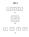
- Fig.6 shows examples of storage states of multiple viewpoint image data 2. Because moving picture data taken by a plurality of cameras need to be temporally synchronized to each other, the plurality of images data C1 to C4 taken by different cameras may be stored in such a manner as to join them abreast and form a piece of image data made of one image, as shown in Fig.6 (a). This format assures that the images data C1 to C4 contained in the image data of the single image were taken at the same time, leading to easy time management.
- the way of joining is not limited to a line abreast as shown in Fig.6 (a) but the images may be joined as shown in Fig.6 (b), for example.
- a format of separately storing the images of data C1 to C4 taken by different cameras may be also considered.
- the advantage of this method is that, when camera images C1 and C2 alone are needed as shown in Fig. 3 (b) in order to generate the image data from the requested viewpoint, these can be easily picked up.
- Multiple viewpoint image data 2 may be stored either by being compressed or non-compressed.
- Fig.8 description will be made about a case where individual pieces of camera image data which are given separately in the manner as shown in Fig. 6 (c) are stored after being data compressed.
- images of data C1 to C4 taken by the individual cameras are input to an encoder 31 as shown in Fig.8 (a).
- Encoder 31 encodes each image data and outputs the necessary information (frame type, generation bit count, etc.) for generating management information, to a management information generator 32.
- the coded image data and the management information are recorded as the storage data (management information adding means). The detail of the management information and storage format will be described later.
- a selector 34 in accordance with the request from the client, selects only the necessary image data from the stored data and outputs to a decoder 35 where the data is decoded, whereby it is possible to obtain the necessary and sufficient original image data (the image data to be used by image generator 3) .
- the management information recorded together with image data is utilized.
- Fig.7 shows examples of image data states generated by image synthesizer 5.
- the left eye viewpoint image data L and the right eye viewpoint image data R can be encoded as separate pieces of image data as shown in Fig.7 (b), it is preferred that both images of data are joined side by side (or up and down) into a piece of synthesized image data formed of a single image then the joined image data is encoded. Formation of the image data composed of a single image as shown in Fig. 7 (a) is able to assure the synchronism between the left eye viewpoint image data L and the right eye viewpoint image data R, leading to easy time management.
- both the left eye viewpoint image L and the right viewpoint image R can be kept substantially equal in image quality.
- the images are encoded as separate pieces of image data, depending on the rate control result there occurs a case where on extraction of a frame at a certain moment the image quality of the left eye viewpoint image L is good while the image quality of the right eye viewpoint image R is bad. In such a case, the resultant stereoscopic display presents poor quality.
- the image data to be finally displayed on the display unit 14 takes a form of strips of left eye viewpoint image data L and strips of right eye viewpoint image data R being alternated with each other every line as shown in Fig.7 (c) (for lenticular mode, parallax barrier mode and the like).
- the image data to be coded takes the form as shown in Fig.7 (a).
- the reason is that if coding is performed on a block basis as in DCT, the image data having the form as shown in Fig.7 (c) will present weak correlation between adjacent pixels, hence high spatial frequencies, producing poor compression efficiency.
- the same method can be applied for the cases where the number of viewpoints is greater than 2.
- a flag for identification indicating whether the image data is of two-dimensional image data or stereoscopic image data may and should be added (identification information addingmeans) .
- This addition of the identification flag may be done either on server 1 or client 11. Further, client 11 has a judgement means for distinction between two-dimensional image data or stereoscopic image data.
- the recording means shouldbe placed before decoding (upstream of decoder 12) or after image processing (downstream of the image processor).
- Fig.9 is a flowchart showing the sequence of processing on server 1.
- the request from a client is analyzed (Step S1).
- the necessary image data is selected from multiple viewpoint image data (Step S2).
- an image from the requested viewpoint is generated based on the selected data (Step S3).
- the image data of a size required for display is cut out (and reduced as required) (Step S4).
- the cutout left eye viewpoint image data and the cutout right eye viewpoint image data are joined (Step S5).
- the joined image data is encoded (Step S6).
- the data is output as a bit stream (Step S7).
- Fig.10 is a flowchart showing the sequence of processing on client 11.
- initialization is done so that the viewpoint position (viewpoint information) at the initial state and information not dependent on the viewpoint (stereoscopic display format, resolution etc. (display unit information)) are set up (Step S11).
- these pieces of information are transmitted as a request to server 1 (Step S12).
- the bit stream (image data) meeting the request is transmitted from the server by way of the network (Step S13).
- the bit stream is decoded (Step S14).
- Step S15 the data is displayed on display unit 14 (Step S16).
- Step S17 it is judged whether there is a next display (Step S17). If display is continued, it is judged whether there is a request for change of the viewpoint (Step S18) . Subsequently, if the viewpoint should be changed, the request is sent again to server 1 and the operation returns to Step S12. When no more display is needed at Step S18, the operation goes to Step S13.
- Fig.14 shows an expected connection state between a server and clients in this embodiment.
- Terminals A to C are the clients and are connected to a server 41 via a network 7.
- Each terminal has a stereoscopic display format and a display resolution different from others, and the position of the viewpoint for observation is different from others. Therefore, server 41, in accordance with the request from each terminal, transmits to the terminal different image data from the others. If the whole multiple viewpoint image data stored (recorded) on server 41 is transmitted to the network so as to permit each terminal to choose the necessary data to display, transmission can be done with one kind of image data. However, since the multiple viewpoint image data is composed of a massive amount of data and because of bandwidth limitations of the network, such a transmission is unfeasible. This is why the transmission system of the present invention in which the server can transmit appropriate image data in accordance with the request from a client is requisite to an environment in which different kinds of terminals are connected to a network.
- Fig.15 is a flowchart showing details of the processing in the image generator 3.
- Step S21 the position of the viewpoint requested from a client is analyzed.
- Step S22 it is judged whether there is any image whose viewpoint corresponds to the requested viewpoint, among the stored multiple viewpoint image data. If there is, the image data is directly used; otherwise the interpolation image is generated (Step S23). Subsequently, the data is output as the image data (Step S24).
- Fig. 11 shows one example of coding a multiple viewpoint moving picture based on MPEG-4. Since frame skipping can be used with MPEG-4, the frames to be coded have discontinuous frame numbers such as LTf0, LTf3, LTf5 and LTf10. Further, in this example, LTf0 is assumed to be coded as an intra frame coding frame (1-frame), LTf10 is assumed to be coded as a frame (P-frame) which is predictive coded based on the decoded frame of LTf0, and LTf3 and LTf5 are assumed to be coded as frames (B-frames) which are bi-directionally predictive coded based on the decoded frames of LTf0 and LTf10.
- LTf0 is assumed to be coded as an intra frame coding frame (1-frame)
- LTf10 is assumed to be coded as a frame (P-frame) which is predictive coded based on the decoded frame of LTf0
- Fig.13 is a chart showing one example of management information added at management information generator 32 shown in Fig. 8 (a).
- the coded data of individual camera images can be joined to management information as shown in Fig.12 and stored.
- This management information is the information that allows for access to each camera image data.
- the management information contains not only the information which allows for access to each camera image but also the information which allows random access to the coded data at a designated time within each camera image data.
- Fig.13 (a) shows one example of management information for access to the coded data of individual camera images.
- the coded data of camera image C2 exists at the B2-th byte from the front of the data in Fig.12.
- Fig.13 (a) further includes the pointers to the information for making access to the coded data at designated times within the camera image data.
- the access table for making access to the coded data at designated times is located at address P2 within the management information.
- Fig.13 (b) shows one example of an access table to coded data at designated times. Times t1, t2, t3, ... may be set up at regular intervals or may be set up arbitrary intervals apart. For example, it is indicated that the coded data corresponding to time t3 exists at the Bt3-th byte from the front of the coded data of the camera image while the coded data of I-frame is located at a position upstream by It3 bytes from the aforementioned position. If the decoder needs to start display from time t3, the coded data of the I-frame located at the (Bt3-It3)-th byte from the front is decoded first.
- the image data distribution system, its image data transmitting apparatus and image data receiving apparatus according to the present invention does not need large amounts of memory and a high-performance CPU on the client side, and can be applied to mobile terminals which enable observations of a stereoscopic image from arbitrary viewpoints.
Abstract
A server (1) analyses the request information transmitted
from a client (11) by means of a request analyzer 4 and selects
the necessary image data from multiple viewpoint image data
(2) to output it to an image generator (3), where image data
for the requested viewpoint is generated by interpolation
to be output to an image synthesizer (5). In the image
synthesizer (5), a plurality of images data are synthesized
in a form suitable for encoding. An encoder (6) encodes the
image data at a suitable bit rate and transfers it to a network
(7). The client (11) receives the encoded image data, decodes
the data through a decoder (12) and outputs the decoded image
data to an image processor (13), where the image data is
converted into an appropriate form in conformity with a
stereoscopic display format and is displayed on a display
unit (14). The client (11) also includes an input unit (16)
for change of the viewpoint, and transmits the request
information of viewpoint alternation to the network (7) by
means of a request output unit (15). Thus this system enables
observation of a stereoscopic image viewed from an arbitrary
viewpoint even with a mobile terminal or the like.
Description
The present invention relates to an image data
distribution system for distributing image data and an image
data transmitting apparatus and image data receiving apparatus
for the system.
Conventionally, there have been proposed devices for
displaying a stereoscopic image viewed from an arbitrary
viewpoint using multiple viewpoint images taken by a plurality
of cameras. One example of such a display device is shown
in Fig. 16. This device includes: an input unit 95 for setting
the left and right eye viewpoints; a computer 91 connected
to input unit 95 to generate image data that constitutes two
images viewed from the left and right eye viewpoints; and
a stereoscopic display 98 that is connected to computer 91
to receive image data of the two images and makes stereoscopic
display by synthesizing the data through an interior circuit
thereof.
From the multiple viewpoint image data stored in memory
92, one desired set of image data is selected while its left
and right eye viewpoints for implementing stereoscopic display
are designated by using the input unit 95. In this case, it
is judged whether the image data viewed from the left eye
viewpoint is present in the multiple-view data. If the data
is present, the image data is output through input/output
interface 94. If the data is not present, the image data that
is viewed from the left eye viewpoint is generated by an
interpolating process using the image data constituting a
predetermined plurality of images taken from the viewpoints
adjacent to the left eye viewpoint, and the generated data
is output through input/output interface 94. A similar
process is carried out from the right eye viewpoint.
However, since the conventional technology needs high
enough memory and a high-performance CPU, it suffers from
the problem of being impossible for a terminal such as a mobile
terminal, which has only limited memory and a CPU with a limited
processing performance, to realize the technology.
Further, since it is assumed in the conventional
technology that a special stereoscopic display is directly
connected to the computer, no consideration is taken for
efficient transmission of image data, so that it is impossible
to deal with the case where various kinds of stereoscopic
displays are connected through a network.
The present invention has been devised under the above
circumstances, it is therefore an object of the present
invention to provide an image data distribution system, its
image data transmitting apparatus and image data receiving
apparatus, which enable observation of a stereoscopic image
viewed from a viewpoint even with a mobile terminal or the
like.
Another object is to enable identical original image
data to be used for observations of a stereoscopic image viewed
from arbitrary viewpoints through various kinds of
stereoscopic displays connected by a network while realizing
efficient transmission of stereoscopic image data.
In order to achieve the above objects, the image data
distribution system according to the present invention and
its image data transmitting apparatus and image data receiving
apparatus employ the following means.
Specifically, an image data distribution system of the
present invention includes: a request information receiving
means for receiving client's request information transmitted
by way of a network; a request information analyzing means
for analyzing the request information received by the request
information receiving means; a multiple viewpoint image supply
means for supplying multiple viewpoint image data; an image
generating means which, based on viewpoint information from
the request information analyzed by the request information
analyzing means, receives input of necessary image data from
the multiple viewpoint image supply means and generates image
data of an image viewed from a predetermined viewpoint in
conformity with the request information; an image synthesizing
means for synthesizing a plurality of images data generated
by the image generating means, based on display unit
information from the request information; a coding means for
coding image data synthesized by the image synthesizing means;
a transmitting means for transmitting coded image data by
the codingmeans to the network; a receivingmeans for receiving
the coded image data via the network; a decoding means for
decoding the coded image data received by the receiving means;
an image processing means for processing decoded image data
by the decoding means so as to be displayable on a display
means; the display means for displaying image data processed
by the image processing means; a request information input
means for allowing input of the client' s request information;
and a request information transmitting means for transmitting
the request information to the network.
Also, an image data transmitting apparatus of the present
invention includes: a request information receiving means
for receiving client's request information transmitted by
way of a network; a request information analyzing means for
analyzing the request information received by the request
information receiving means; a multiple viewpoint image supply
means for supplying multiple viewpoint image data; an image
generating means which, based on viewpoint information from
the request information analyzed by the request information
analyzing means, receives input of necessary image data from
the multiple viewpoint image supply means and generates image
data of an image viewed from a predetermined viewpoint in
conformity with the request information; an image synthesizing
means for synthesizing a plurality of images data generated
by the image generating means, based on display unit
information from the request information; a coding means for
coding image data synthesized by the image synthesizing means;
and a transmitting means for transmitting coded image data
by the coding means to the network.
Further, an image data receiving apparatus of the present
invention includes: a receiving means for receiving coded
image data by way of a network; a decoding means for decoding
the coded image data received by the receiving means; an image
processing means for processing decoded image data by the
decoding means so as to be displayable on a display means;
the display means for displaying image data processed by the
image processing means; a request information input means
for allowing input of request information of a client; and
a request information transmitting means for transmitting
the request information to the network.
Moreover, the image data distribution system and the
image data transmitting apparatus of the present invention
may further include a management information adding means
for adding management information for enabling access to the
image data of individual viewpoints and random access, to
the multiple viewpoint image data.
Sill, the image data distributing system and the image
data receiving means of the present invention may further
include a judgement means for judging whether the received
image data is of two-dimensional image data or stereoscopic
image data.
Still more, the image data distribution system, the image
data transmitting apparatus and the image data receiving means
of the present invention may further includes an
identification information adding means for adding to the
image data to be transmitted or the received image data a
piece of information that indicates whether the image data
is of two-dimensional image data or stereoscopic image data.
As has been described heretofore, since the above
configuration makes it unnecessary to provide large amounts
of memory and a high-performance CPU on the client side, the
invention has the effect of enabling observation of a
stereoscopic image viewed from an arbitrary viewpoint even
with a mobile terminal and the like.
The present invention also has the effect of enabling
use of an identical original image data to provide observations
of a stereoscopic image viewed from arbitrary viewpoints
through various types of stereoscopic displays that are
connected by way of a network.
The embodiment of an image data distribution system
according to the present invention will be described with
reference to the drawings.
Fig.1 is a block diagram showing the embodiment of an
image data distribution system according to the present
invention.
A server 1 (image data transmitting apparatus) and a
client 11 (image data receiving apparatus) are connected to
each other byway of a network 7. Server 1 has stored (recorded)
multiple viewpoint image data 2. When client 11 transmits
request information to server 1, the client is able to implement
stereoscopic display of an image viewed from a desired
viewpoint on a display unit 14.
Here, the multiple viewpoint image data has not been
necessarily stored (recorded) previously in server 1, but
may be supplied in real time from without.
Server 1 analyses the request information transmitted
from client 11 by a request analyzer 4 (request information
analyzing means (including request information receiving
means)) and selects the necessary image data from multiple
viewpoint image data 2 (multiple viewpoint image supply means)
to output it to an image generator 3 (image generating means)
where image data for the requested viewpoint (viewpoint
information) is generated by interpolation to be output to
an image synthesizer 5 (image synthesizing means). In image
synthesizer 5, a plurality of supplied images data are
synthesized in a form (format based on the display unit
information) suitable for encoding to be output to an encoder
6 (coding means). In encoder 6, the supplied image data is
encoded at a suitable bit rate to be transmitted to network
7 (transmitting means).
Now, server 1 and client 11 will be described in detail.
Multiple viewpoint image data 2 is formed of a set of
images data taken by a plurality of cameras. The plurality
of cameras are typically laid out as shown in Fig.2 (a) so
that the optical axes of the plurality of cameras intersect
at one point. As a special example, the cameras may be arranged
on the circumference of a circle so that the optical axes
of the cameras are directed to the center of the circle, as
shown in Fig.2 (b). In either case, the cameras are not
necessarily arranged equi-distantly, but may be laid out in
some parts densely and others sparsely. The information as
to how the cameras are allocated is also recorded together
with the image data. This allocation information is used to
determine the image data of which cameras should be used when
image generator 3 generates the image data from a designated
viewpoint by interpolation based on the request information
from client 11.
Next, description will be made about the necessary camera
image data when the image of the requested viewpoint is
generated by interpolation. In the example shown in Fig.3
(a) , the left eye viewpoint L and right eye viewpoint R are
designated as illustrated with respect to cameras C1 to C4.
In this case, the images of data from C1 and C2 are used to
generate the image data for left eye viewpoint L and the images
of data from C2 and C3 are used to generate the image data
for right eye viewpoint R. Similarly, in the example shown
in Fig. 3 (b) , the layout of cameras C1 to C4 and the requested
left eye viewpoint L and right eye viewpoint R are positioned
as illustrated. In this case, both the image data for left
eye viewpoint L and the image data for right eye viewpoint
R are generated based on the images of data from C1 and C2.
Though four cameras are used in the examples in Fig.3, the
number of cameras is not limited to four.
Generation of images from an intermediate viewpoint by
interpolation is a known technology, and is disclosed in detail
in, for example, "Tsunashima et al.: generation of
intermediate image data from a two-view stereoscopic image
data taking occlusion into consideration, 3D Image Conference
'95, pp. 174-177 (1995)", and "Azuma et al.: parallax
estimation based on the edge information for generation of
intermediate image data, 3D Image Conference 95, pp. 190-194
(1995)", and others.
When the necessary viewpoint image data has been
generated at image generator 3, image synthesizer 5 implements
an extraction process of image data in an amount for the
requested resolution. In Fig. 4 (a), the size of the generated
image data 21 is assumed to be equal to the size of the image
taken by the camera, and the resolution required for display
on client 11 is shown by an area 22. In Fig.4 (a), only part
of the generated image data is cut out. Alternatively, as
shown in Fig.4 (b), instead of cutting out an image in the
resolution required for display on client 11, the maximum
area 24 capable of being cut out while keeping the display
aspect may be cut out from the generated image data 23 (which
is assumed to be the same size as the image taken by the camera) ,
then may be reduced to the required resolution. Also, image
generator 3 may be adapted to generate only the necessary
amount of image data for the required resolution.
Fig.5 is an illustrative view showing a mobile terminal
50 to be a client 11. The terminal includes a stereoscopic
display 54, a four-way arrow key 51 for moving the viewpoint
up, down, left and right and keys 52 and 53 for moving the
viewpoint forward and backward. Though unillustrated, the
terminal also has a communication means for making
communication with the server.
Fig.6 shows examples of storage states of multiple
viewpoint image data 2. Because moving picture data taken
by a plurality of cameras need to be temporally synchronized
to each other, the plurality of images data C1 to C4 taken
by different cameras may be stored in such a manner as to
join them abreast and form a piece of image data made of one
image, as shown in Fig.6 (a). This format assures that the
images data C1 to C4 contained in the image data of the single
image were taken at the same time, leading to easy time
management. The way of joining is not limited to a line abreast
as shown in Fig.6 (a) but the images may be joined as shown
in Fig.6 (b), for example.
In contrast, as shown in Fig. 6 (c) , a format of separately
storing the images of data C1 to C4 taken by different cameras
may be also considered. The advantage of this method is that,
when camera images C1 and C2 alone are needed as shown in
Fig. 3 (b) in order to generate the image data from the requested
viewpoint, these can be easily picked up.
Multiple viewpoint image data 2 may be stored either
by being compressed or non-compressed. Here, referring to
Fig.8, description will be made about a case where individual
pieces of camera image data which are given separately in
the manner as shown in Fig. 6 (c) are stored after being data
compressed. In this case, images of data C1 to C4 taken by
the individual cameras are input to an encoder 31 as shown
in Fig.8 (a). Encoder 31 encodes each image data and outputs
the necessary information (frame type, generation bit count,
etc.) for generating management information, to a management
information generator 32. In a recorder 33, the coded image
data and the management information are recorded as the storage
data (management information adding means). The detail of
the management information and storage format will be
described later.
When the storage data which has been recorded in the
manner shown in Fig.8 (a) is used as the multiple viewpoint
image data, the data needs to be decoded so as to be handled
by image generator 3. In this case, as shown in Fig.8 (b),
a selector 34, in accordance with the request from the client,
selects only the necessary image data from the stored data
and outputs to a decoder 35 where the data is decoded, whereby
it is possible to obtain the necessary and sufficient original
image data (the image data to be used by image generator 3) .
In this process, in order to extract the necessary part quickly,
the management information recorded together with image data
is utilized.
Fig.7 shows examples of image data states generated by
image synthesizer 5. Though the left eye viewpoint image data
L and the right eye viewpoint image data R can be encoded
as separate pieces of image data as shown in Fig.7 (b), it
is preferred that both images of data are joined side by side
(or up and down) into a piece of synthesized image data formed
of a single image then the joined image data is encoded.
Formation of the image data composed of a single image as
shown in Fig. 7 (a) is able to assure the synchronism between
the left eye viewpoint image data L and the right eye viewpoint
image data R, leading to easy time management. Particularly,
when a coding scheme entailing frame skipping such as MPEG-4
is used, it is possible to prevent occurrence of such a situation
where, at a certain moment, the frame of the left eye viewpoint
image data L is present whereas the frame of the right eye
viewpoint image data R is not present. Further, since the
image data is rate-controlled as a single image, both the
left eye viewpoint image L and the right viewpoint image R
can be kept substantially equal in image quality. When the
images are encoded as separate pieces of image data, depending
on the rate control result there occurs a case where on
extraction of a frame at a certain moment the image quality
of the left eye viewpoint image L is good while the image
quality of the right eye viewpoint image R is bad. In such
a case, the resultant stereoscopic display presents poor
quality. Thus, it is possible to improve the quality of
stereoscopic display when the data is adapted to take the
form as shown in Fig.7 (a).
Depending on the stereoscopic display format of a client
11, there are some cases where the image data to be finally
displayed on the display unit 14 takes a form of strips of
left eye viewpoint image data L and strips of right eye viewpoint
image data R being alternated with each other every line as
shown in Fig.7 (c) (for lenticular mode, parallax barrier
mode and the like). In such a case, however, it is preferred
that the image data to be coded takes the form as shown in
Fig.7 (a). The reason is that if coding is performed on a
block basis as in DCT, the image data having the form as shown
in Fig.7 (c) will present weak correlation between adjacent
pixels, hence high spatial frequencies, producing poor
compression efficiency. The same method can be applied for
the cases where the number of viewpoints is greater than 2.
When images of data for a plurality of viewpoints are
joined to form a piece of image data made of a single image
as shown in Fig.7 (a) , it is impossible to know the difference
between normal two-dimensional image data and stereoscopic
image data from a format point of view. No problem will occur
when real-time streaming is handled using the system shown
in Fig.1 because image data is transmitted in real time in
accordance with the request from the client side. However,
in a case where the thus transmitted image data has been once
recorded locally on the client 11 side and is played afterward,
it is impossible to distinguish whether it is of
two-dimensional image data or stereoscopic image data. In
order to prevent this, when any piece of image data having
the form as shown in Fig.7 (a) is recorded, a flag for
identification indicating whether the image data is of
two-dimensional image data or stereoscopic image data may
and should be added (identification information addingmeans) .
This addition of the identification flag may be done either
on server 1 or client 11. Further, client 11 has a judgement
means for distinction between two-dimensional image data or
stereoscopic image data.
In connection with the above, when client 11 records
image data locally, the recording means shouldbe placed before
decoding (upstream of decoder 12) or after image processing
(downstream of the image processor).
Fig.9 is a flowchart showing the sequence of processing
on server 1. First, the request from a client is analyzed
(Step S1). Then, the necessary image data is selected from
multiple viewpoint image data (Step S2). Next, an image from
the requested viewpoint is generated based on the selected
data (Step S3). Subsequently, the image data of a size
required for display is cut out (and reduced as required)
(Step S4). Then, the cutout left eye viewpoint image data
and the cutout right eye viewpoint image data are joined (Step
S5). Next, the joined image data is encoded (Step S6).
Finally, the data is output as a bit stream (Step S7).
Fig.10 is a flowchart showing the sequence of processing
on client 11. First, initialization is done so that the
viewpoint position (viewpoint information) at the initial
state and information not dependent on the viewpoint
(stereoscopic display format, resolution etc. (display unit
information)) are set up (Step S11). Next, these pieces of
information are transmitted as a request to server 1 (Step
S12). Then, the bit stream (image data) meeting the request
is transmitted from the server by way of the network (Step
S13). Subsequently, the bit stream is decoded (Step S14).
Since, as shown in Fig.7 (a) the decoded image data is not
in the form that is directly and stereoscopically displayable,
the data is rearranged so as to conform with the stereoscopic
display format, as shown in Fig.7 (c) (Step S15). Then the
data is displayed on display unit 14 (Step S16). Next, it
is judged whether there is a next display (Step S17). If
display is continued, it is judged whether there is a request
for change of the viewpoint (Step S18) . Subsequently, if the
viewpoint should be changed, the request is sent again to
server 1 and the operation returns to Step S12. When no more
display is needed at Step S18, the operation goes to Step
S13.
Fig.14 shows an expected connection state between a
server and clients in this embodiment. Terminals A to C are
the clients and are connected to a server 41 via a network
7. Each terminal has a stereoscopic display format and a
display resolution different from others, and the position
of the viewpoint for observation is different from others.
Therefore, server 41, in accordance with the request from
each terminal, transmits to the terminal different image data
from the others. If the whole multiple viewpoint image data
stored (recorded) on server 41 is transmitted to the network
so as to permit each terminal to choose the necessary data
to display, transmission can be done with one kind of image
data. However, since the multiple viewpoint image data is
composed of a massive amount of data and because of bandwidth
limitations of the network, such a transmission is unfeasible.
This is why the transmission system of the present invention
in which the server can transmit appropriate image data in
accordance with the request from a client is requisite to
an environment in which different kinds of terminals are
connected to a network.
Fig.15 is a flowchart showing details of the processing
in the image generator 3. First, the position of the viewpoint
requested from a client is analyzed (Step S21). Next, it is
judged whether there is any image whose viewpoint corresponds
to the requested viewpoint, among the stored multiple
viewpoint image data (Step S22). If there is, the image data
is directly used; otherwise the interpolation image is
generated (Step S23). Subsequently, the data is output as
the image data (Step S24).
Next, management information will be described.
Fig. 11 shows one example of coding a multiple viewpoint
moving picture based on MPEG-4. Since frame skipping can be
used with MPEG-4, the frames to be coded have discontinuous
frame numbers such as LTf0, LTf3, LTf5 and LTf10. Further,
in this example, LTf0 is assumed to be coded as an intra frame
coding frame (1-frame), LTf10 is assumed to be coded as a
frame (P-frame) which is predictive coded based on the decoded
frame of LTf0, and LTf3 and LTf5 are assumed to be coded as
frames (B-frames) which are bi-directionally predictive coded
based on the decoded frames of LTf0 and LTf10.
Fig.13 is a chart showing one example of management
information added at management information generator 32 shown
in Fig. 8 (a). The coded data of individual camera images can
be joined to management information as shown in Fig.12 and
stored. This management information is the information that
allows for access to each camera image data. In the case of
a multiple viewpoint moving picture, the management
information contains not only the information which allows
for access to each camera image but also the information which
allows random access to the coded data at a designated time
within each camera image data.
Fig.13 (a) shows one example of management information
for access to the coded data of individual camera images.
For example, it is indicated that the coded data of camera
image C2 exists at the B2-th byte from the front of the data
in Fig.12. Fig.13 (a) further includes the pointers to the
information for making access to the coded data at designated
times within the camera image data. For the coded data of
C2, it is indicated that the access table for making access
to the coded data at designated times is located at address
P2 within the management information.
Fig.13 (b) shows one example of an access table to coded
data at designated times. Times t1, t2, t3, ... may be set
up at regular intervals or may be set up arbitrary intervals
apart. For example, it is indicated that the coded data
corresponding to time t3 exists at the Bt3-th byte from the
front of the coded data of the camera image while the coded
data of I-frame is located at a position upstream by It3 bytes
from the aforementioned position. If the decoder needs to
start display from time t3, the coded data of the I-frame
located at the (Bt3-It3)-th byte from the front is decoded
first. Then, P-frames and B-frames are successively decoded
while counting the number of bytes of the decoded data until
the count reaches It3 bytes. When the display is started at
this point of time, the image data from the designated time
t3 is displayed.
Next, other accessing methods will be described.
The image data distribution system, its image data
transmitting apparatus and image data receiving apparatus
according to the present invention does not need large amounts
of memory and a high-performance CPU on the client side, and
can be applied to mobile terminals which enable observations
of a stereoscopic image from arbitrary viewpoints.
Claims (10)
- An image data distribution system comprising:a request information receiving means for receiving client's request information transmitted by way of a network;a request information analyzing means for analyzing the request information received by the request information receiving means;a multiple viewpoint image supply means for supplying multiple viewpoint image data;an image generating means which, based on viewpoint information from the request information analyzed by the request information analyzing means, receives input of necessary image data from the multiple viewpoint image supply means and generates image data of an image viewed from a predetermined viewpoint in conformity with the request information;an image synthesizing means for synthesizing a plurality of images data generated by the image generating means, based on display unit information from the request information;a coding means for coding image data synthesized by the image synthesizing means;a transmitting means for transmitting coded image data by the coding means to the network;a receiving means for receiving the coded image data via the network;a decoding means for decoding the coded image data received by the receiving means;an image processing means for processing decoded image data by the decoding means so as to be displayable on a display means;the display means for displaying image data processed by the image processing means;a request information input means for allowing input of the client's request information; anda request information transmitting means for transmitting the request information to the network.
- An image data transmitting apparatus comprising:a request information receiving means for receiving client's request information transmitted by way of a network;a request information analyzing means for analyzing the request information received by the request information receiving means;a multiple viewpoint image supply means for supplying multiple viewpoint image data;an image generating means which, based on viewpoint information from the request information analyzed by the request information analyzing means, receives input of necessary image data from the multiple viewpoint image supply means and generates image data of an image viewed from a predetermined viewpoint in conformity with the request information;an image synthesizing means for synthesizing a plurality of images data generated by the image generating means, based on display unit information from the request information;a coding means for coding image data synthesized by the image synthesizing means; anda transmitting means for transmitting coded image data by the coding means to the network.
- An image data receiving apparatus comprising:a receiving means for receiving coded image data by way of a network;a decoding means for decoding the coded image data received by the receiving means;an image processing means for processing decoded image data by the decoding means so as to be displayable on a display means;the display means for displaying image data processed by the image processing means;a request information input means for allowing input of request information of a client; anda request information transmitting means for transmitting the request information to the network.
- The image data distributing system according to Claim 1, further comprising a management information adding means for adding management information for enabling access to the image data of individual viewpoints and random access, to the multiple viewpoint image data.
- The image data transmitting apparatus according to Claim 2, further comprising a management information adding means for adding management information for enabling access to the image data of individual viewpoints and random access, to the multiple viewpoint image data.
- The image data distributing system according to Claim 1 or 4, further comprising a judgement means for judging whether the received image data is of two-dimensional image data or stereoscopic image data.
- The image data receiving apparatus according to Claim 3, further comprising a judgement means for judging whether the received image data is of two-dimensional image data or stereoscopic image data.
- The image data distributing system according to one of Claims 1, 4 and 6, further comprising an identification information adding means for adding to the image data to be transmitted a piece of information that indicates whether the image data is of two-dimensional image data or stereoscopic image data.
- The image data transmitting apparatus according to Claim 2 or 5, further comprising an identification information adding means for adding to the image data to be transmitted a piece of information that indicates whether the image data is of two-dimensional image data or stereoscopic image data.
- The image data receiving apparatus according to Claim 3 or 7, further comprising an identification information adding means for adding to the received image data a piece of information that indicates whether the image data is of two-dimensional image data or stereoscopic image data.
Applications Claiming Priority (3)
| Application Number | Priority Date | Filing Date | Title |
|---|---|---|---|
| JP2002189470 | 2002-06-28 | ||
| JP2002189470 | 2002-06-28 | ||
| PCT/JP2003/008302 WO2004004350A1 (en) | 2002-06-28 | 2003-06-30 | Image data delivery system, image data transmitting device thereof, and image data receiving device thereof |
Publications (2)
| Publication Number | Publication Date |
|---|---|
| EP1519582A1 true EP1519582A1 (en) | 2005-03-30 |
| EP1519582A4 EP1519582A4 (en) | 2007-01-31 |
Family
ID=29996848
Family Applications (1)
| Application Number | Title | Priority Date | Filing Date |
|---|---|---|---|
| EP03761837A Withdrawn EP1519582A4 (en) | 2002-06-28 | 2003-06-30 | Image data delivery system, image data transmitting device thereof, and image data receiving device thereof |
Country Status (7)
| Country | Link |
|---|---|
| US (1) | US7734085B2 (en) |
| EP (1) | EP1519582A4 (en) |
| JP (1) | JP4346548B2 (en) |
| KR (1) | KR100742674B1 (en) |
| CN (1) | CN100342733C (en) |
| AU (1) | AU2003244156A1 (en) |
| WO (1) | WO2004004350A1 (en) |
Cited By (8)
| Publication number | Priority date | Publication date | Assignee | Title |
|---|---|---|---|---|
| WO2007043775A1 (en) * | 2005-10-07 | 2007-04-19 | Electronics And Telecommunications Research Institute | Method and apparatus for encoding and decoding hopping default view for multiple cameras system |
| WO2009027923A1 (en) * | 2007-08-31 | 2009-03-05 | Koninklijke Philips Electronics N.V. | Conveying auxiliary information in a multiplexed stream |
| EP2227021A1 (en) * | 2007-12-28 | 2010-09-08 | Huawei Device Co., Ltd. | An apparatus, system and method for multi-view photographing and image processing and a decoding processing method |
| WO2014039265A1 (en) * | 2012-09-10 | 2014-03-13 | Utc Fire & Security Americas Corporation, Inc. | Systems and methods for security panel content management |
| EP2908520A1 (en) * | 2014-02-14 | 2015-08-19 | Thomson Licensing | Method for displaying a 3D content on a multi-view display device, corresponding multi-view display device and computer program product |
| EP3198863A4 (en) * | 2014-09-22 | 2017-09-27 | Samsung Electronics Co., Ltd. | Transmission of three-dimensional video |
| US11049218B2 (en) | 2017-08-11 | 2021-06-29 | Samsung Electronics Company, Ltd. | Seamless image stitching |
| US11205305B2 (en) | 2014-09-22 | 2021-12-21 | Samsung Electronics Company, Ltd. | Presentation of three-dimensional video |
Families Citing this family (36)
| Publication number | Priority date | Publication date | Assignee | Title |
|---|---|---|---|---|
| JP2006113807A (en) | 2004-10-14 | 2006-04-27 | Canon Inc | Image processor and image processing program for multi-eye-point image |
| JP2006165878A (en) * | 2004-12-06 | 2006-06-22 | Shigeru Handa | Content distribution system and data structure |
| JP4738870B2 (en) * | 2005-04-08 | 2011-08-03 | キヤノン株式会社 | Information processing method, information processing apparatus, and remote mixed reality sharing apparatus |
| JP4687279B2 (en) * | 2005-06-29 | 2011-05-25 | ソニー株式会社 | Image reproduction apparatus, image reproduction method, and image reproduction program |
| JP4665166B2 (en) * | 2005-06-29 | 2011-04-06 | ソニー株式会社 | Stereo image processing apparatus, stereo image processing method, and stereo image processing program |
| JP4665167B2 (en) * | 2005-06-29 | 2011-04-06 | ソニー株式会社 | Stereo image processing apparatus, stereo image processing method, and stereo image processing program |
| KR20070008289A (en) * | 2005-07-13 | 2007-01-17 | 삼성전자주식회사 | Display apparatus and information processing system with the same, and driving method thereof |
| KR100755457B1 (en) * | 2005-08-16 | 2007-09-05 | 홍길철 | Method of Providing Multiple or 3-dimensional Picture Using Internet Network |
| WO2007122907A1 (en) * | 2006-03-29 | 2007-11-01 | Matsushita Electric Industrial Co., Ltd. | Image codec device |
| WO2008035654A1 (en) * | 2006-09-20 | 2008-03-27 | Nippon Telegraph And Telephone Corporation | Image encoding and decoding methods, their devices, image decoding device, their programs, and storage medium in which programs are recorded |
| US8184692B2 (en) * | 2006-09-25 | 2012-05-22 | Framecaster, Inc. | Distributed and automated video encoding and delivery system |
| JP5029062B2 (en) * | 2007-02-26 | 2012-09-19 | 富士通株式会社 | Multi-view video transmission system |
| JP2010169777A (en) * | 2009-01-21 | 2010-08-05 | Sony Corp | Image processing device, image processing method and program |
| JP5627860B2 (en) | 2009-04-27 | 2014-11-19 | 三菱電機株式会社 | 3D image distribution system, 3D image distribution method, 3D image distribution device, 3D image viewing system, 3D image viewing method, 3D image viewing device |
| US8953017B2 (en) | 2009-05-14 | 2015-02-10 | Panasonic Intellectual Property Management Co., Ltd. | Source device, sink device, communication system and method for wirelessly transmitting three-dimensional video data using packets |
| KR20100131061A (en) * | 2009-06-05 | 2010-12-15 | 삼성전자주식회사 | Apparatus and method for stereo images processing |
| KR101234495B1 (en) * | 2009-10-19 | 2013-02-18 | 한국전자통신연구원 | Terminal, node device and method for processing stream in video conference system |
| KR101320350B1 (en) * | 2009-12-14 | 2013-10-23 | 한국전자통신연구원 | Secure management server and video data managing method of secure management server |
| KR101329057B1 (en) * | 2010-03-29 | 2013-11-14 | 한국전자통신연구원 | An apparatus and method for transmitting multi-view stereoscopic video |
| JP5515988B2 (en) * | 2010-04-05 | 2014-06-11 | ソニー株式会社 | Signal processing apparatus, signal processing method, display apparatus, and program |
| CN105939469A (en) * | 2010-09-03 | 2016-09-14 | 索尼公司 | Encoding device, encoding method, decoding device and decoding method |
| CN102402412B (en) * | 2010-09-19 | 2014-12-31 | 联想(北京)有限公司 | Display function processing module, server and display processing method |
| JP2012134893A (en) * | 2010-12-24 | 2012-07-12 | Hitachi Consumer Electronics Co Ltd | Receiver |
| JP2012235308A (en) * | 2011-04-28 | 2012-11-29 | Sony Corp | Device and method for image data transmission, and device and method for image data reception |
| CN103179302B (en) * | 2011-12-22 | 2017-10-10 | 腾讯科技(深圳)有限公司 | Image processing method and system in open platform |
| CN104041027A (en) * | 2012-01-06 | 2014-09-10 | 奥崔迪合作公司 | Display Processor For 3d Display |
| JP2014007648A (en) * | 2012-06-26 | 2014-01-16 | Sony Corp | Image processing device, and image processing method and program |
| KR101521890B1 (en) * | 2014-03-28 | 2015-05-22 | 주식회사 넥스트이온 | Multi-view video steaming system and providing method thereof |
| USD748196S1 (en) | 2014-08-27 | 2016-01-26 | Outerwall Inc. | Consumer operated kiosk for sampling products |
| DE102014226122A1 (en) * | 2014-12-16 | 2016-06-16 | Robert Bosch Gmbh | Transcoder device and server-client arrangement with the transcoder device |
| JP6452429B2 (en) * | 2014-12-18 | 2019-01-16 | ヤフー株式会社 | Image processing apparatus, image processing method, and image processing program |
| JP2016220113A (en) * | 2015-05-22 | 2016-12-22 | 株式会社ソシオネクスト | Video distribution device, method and system for video distribution |
| US10129579B2 (en) | 2015-10-15 | 2018-11-13 | At&T Mobility Ii Llc | Dynamic video image synthesis using multiple cameras and remote control |
| JP6770939B2 (en) * | 2017-09-28 | 2020-10-21 | Kddi株式会社 | Video distribution server, video distribution method and video distribution program |
| CN108055324A (en) * | 2017-12-13 | 2018-05-18 | 济南汇通远德科技有限公司 | A kind of method that data interaction is realized based on intelligence wearing product |
| CN110913202B (en) * | 2019-11-26 | 2022-01-07 | 深圳英伦科技股份有限公司 | Three-dimensional display cloud rendering method and system |
Citations (6)
| Publication number | Priority date | Publication date | Assignee | Title |
|---|---|---|---|---|
| EP0888018A1 (en) * | 1996-02-28 | 1998-12-30 | Matsushita Electric Industrial Co., Ltd. | High-resolution optical disk for recording stereoscopic video, optical disk reproducing device, and optical disk recording device |
| WO2001028309A2 (en) * | 1999-10-15 | 2001-04-26 | Kewazinga Corp. | Method and system for comparing multiple images utilizing a navigable array of cameras |
| EP1117256A1 (en) * | 1999-06-25 | 2001-07-18 | Matsushita Electric Industrial Co., Ltd. | All-around video output method and device |
| US6285392B1 (en) * | 1998-11-30 | 2001-09-04 | Nec Corporation | Multi-site television conference system and central control apparatus and conference terminal for use with the system |
| WO2001065854A1 (en) * | 2000-03-01 | 2001-09-07 | Innovue, Inc. | Interactive navigation through real-time live video space created in a given remote geographic location |
| US20020030675A1 (en) * | 2000-09-12 | 2002-03-14 | Tomoaki Kawai | Image display control apparatus |
Family Cites Families (17)
| Publication number | Priority date | Publication date | Assignee | Title |
|---|---|---|---|---|
| JPH01107247A (en) | 1987-10-21 | 1989-04-25 | Matsushita Electric Ind Co Ltd | Three-dimensional video display device |
| JPH07274211A (en) | 1994-03-30 | 1995-10-20 | Sanyo Electric Co Ltd | Method and device for converting two-dimension image into three-dimension image |
| JPH09200715A (en) | 1996-01-19 | 1997-07-31 | Canon Inc | Equipment, method and system for communication |
| EP0931420A4 (en) * | 1996-10-11 | 2002-06-26 | Sarnoff Corp | Stereoscopic video coding and decoding apparatus and method |
| JPH10178594A (en) | 1996-12-19 | 1998-06-30 | Sanyo Electric Co Ltd | Three-dimensional video transmitting method, digital broadcast system and user side terminal |
| US5864337A (en) * | 1997-07-22 | 1999-01-26 | Microsoft Corporation | Mehtod for automatically associating multimedia features with map views displayed by a computer-implemented atlas program |
| GB9800397D0 (en) * | 1998-01-09 | 1998-03-04 | Philips Electronics Nv | Virtual environment viewpoint control |
| JPH11225160A (en) | 1998-02-05 | 1999-08-17 | Chokosoku Network Computer Gijutsu Kenkyusho:Kk | Moving image transfer method and server |
| KR100345235B1 (en) * | 1998-11-08 | 2005-07-29 | 엘지전자 주식회사 | Method and apparatus for re-cording digital data streams |
| US6631205B1 (en) * | 1999-01-13 | 2003-10-07 | Canon Kabushiki Kaisha | Stereoscopic imaging in a portable document format |
| US6525732B1 (en) * | 2000-02-17 | 2003-02-25 | Wisconsin Alumni Research Foundation | Network-based viewing of images of three-dimensional objects |
| KR20010100539A (en) | 2000-05-03 | 2001-11-14 | 박승준 | 2D stereoscopic image producting method using a multi-view stereoscopic image displayer |
| US6573912B1 (en) * | 2000-11-07 | 2003-06-03 | Zaxel Systems, Inc. | Internet system for virtual telepresence |
| US6803912B1 (en) * | 2001-08-02 | 2004-10-12 | Mark Resources, Llc | Real time three-dimensional multiple display imaging system |
| US7091931B2 (en) * | 2001-08-17 | 2006-08-15 | Geo-Rae Co., Ltd. | Method and system of stereoscopic image display for guiding a viewer's eye motion using a three-dimensional mouse |
| JP4148671B2 (en) * | 2001-11-06 | 2008-09-10 | ソニー株式会社 | Display image control processing apparatus, moving image information transmission / reception system, display image control processing method, moving image information transmission / reception method, and computer program |
| JP3922543B2 (en) * | 2002-06-05 | 2007-05-30 | ソニー株式会社 | Imaging device and image display device |
-
2003
- 2003-06-30 JP JP2004517332A patent/JP4346548B2/en not_active Expired - Fee Related
- 2003-06-30 KR KR1020047021448A patent/KR100742674B1/en not_active IP Right Cessation
- 2003-06-30 WO PCT/JP2003/008302 patent/WO2004004350A1/en active Application Filing
- 2003-06-30 EP EP03761837A patent/EP1519582A4/en not_active Withdrawn
- 2003-06-30 AU AU2003244156A patent/AU2003244156A1/en not_active Abandoned
- 2003-06-30 US US10/519,154 patent/US7734085B2/en not_active Expired - Fee Related
- 2003-06-30 CN CNB038153718A patent/CN100342733C/en not_active Expired - Fee Related
Patent Citations (6)
| Publication number | Priority date | Publication date | Assignee | Title |
|---|---|---|---|---|
| EP0888018A1 (en) * | 1996-02-28 | 1998-12-30 | Matsushita Electric Industrial Co., Ltd. | High-resolution optical disk for recording stereoscopic video, optical disk reproducing device, and optical disk recording device |
| US6285392B1 (en) * | 1998-11-30 | 2001-09-04 | Nec Corporation | Multi-site television conference system and central control apparatus and conference terminal for use with the system |
| EP1117256A1 (en) * | 1999-06-25 | 2001-07-18 | Matsushita Electric Industrial Co., Ltd. | All-around video output method and device |
| WO2001028309A2 (en) * | 1999-10-15 | 2001-04-26 | Kewazinga Corp. | Method and system for comparing multiple images utilizing a navigable array of cameras |
| WO2001065854A1 (en) * | 2000-03-01 | 2001-09-07 | Innovue, Inc. | Interactive navigation through real-time live video space created in a given remote geographic location |
| US20020030675A1 (en) * | 2000-09-12 | 2002-03-14 | Tomoaki Kawai | Image display control apparatus |
Non-Patent Citations (3)
| Title |
|---|
| AVARO O ET AL: "The MPEG-4 systems and description languages: A way ahead in audio visual information representation" SIGNAL PROCESSING. IMAGE COMMUNICATION, ELSEVIER SCIENCE PUBLISHERS, AMSTERDAM, NL, vol. 9, no. 4, May 1997 (1997-05), pages 385-431, XP004075337 ISSN: 0923-5965 * |
| See also references of WO2004004350A1 * |
| WEEMS C C JR: "The second generation image understanding architecture and beyond" COMPUTER ARCHITECTURES FOR MACHINE PERCEPTION, 1993. PROCEEDINGS NEW ORLEANS, LA, USA 15-17 DEC. 1993, LOS ALAMITOS, CA, USA,IEEE COMPUT. SOC, 15 December 1993 (1993-12-15), pages 276-285, XP010245378 ISBN: 0-8186-5420-1 * |
Cited By (15)
| Publication number | Priority date | Publication date | Assignee | Title |
|---|---|---|---|---|
| WO2007043775A1 (en) * | 2005-10-07 | 2007-04-19 | Electronics And Telecommunications Research Institute | Method and apparatus for encoding and decoding hopping default view for multiple cameras system |
| WO2009027923A1 (en) * | 2007-08-31 | 2009-03-05 | Koninklijke Philips Electronics N.V. | Conveying auxiliary information in a multiplexed stream |
| EP2227021A1 (en) * | 2007-12-28 | 2010-09-08 | Huawei Device Co., Ltd. | An apparatus, system and method for multi-view photographing and image processing and a decoding processing method |
| EP2227021A4 (en) * | 2007-12-28 | 2010-12-29 | Huawei Device Co Ltd | An apparatus, system and method for multi-view photographing and image processing and a decoding processing method |
| WO2014039265A1 (en) * | 2012-09-10 | 2014-03-13 | Utc Fire & Security Americas Corporation, Inc. | Systems and methods for security panel content management |
| EP2908519A1 (en) * | 2014-02-14 | 2015-08-19 | Thomson Licensing | Method for displaying a 3D content on a multi-view display device, corresponding multi-view display device and computer program product |
| EP2908520A1 (en) * | 2014-02-14 | 2015-08-19 | Thomson Licensing | Method for displaying a 3D content on a multi-view display device, corresponding multi-view display device and computer program product |
| US9967551B2 (en) | 2014-02-14 | 2018-05-08 | Thomson Licensing | Method for displaying a 3D content on a multi-view display device, corresponding multi-view display device and computer program product |
| EP3198863A4 (en) * | 2014-09-22 | 2017-09-27 | Samsung Electronics Co., Ltd. | Transmission of three-dimensional video |
| US10257494B2 (en) | 2014-09-22 | 2019-04-09 | Samsung Electronics Co., Ltd. | Reconstruction of three-dimensional video |
| US10313656B2 (en) | 2014-09-22 | 2019-06-04 | Samsung Electronics Company Ltd. | Image stitching for three-dimensional video |
| US10547825B2 (en) | 2014-09-22 | 2020-01-28 | Samsung Electronics Company, Ltd. | Transmission of three-dimensional video |
| US10750153B2 (en) | 2014-09-22 | 2020-08-18 | Samsung Electronics Company, Ltd. | Camera system for three-dimensional video |
| US11205305B2 (en) | 2014-09-22 | 2021-12-21 | Samsung Electronics Company, Ltd. | Presentation of three-dimensional video |
| US11049218B2 (en) | 2017-08-11 | 2021-06-29 | Samsung Electronics Company, Ltd. | Seamless image stitching |
Also Published As
| Publication number | Publication date |
|---|---|
| CN100342733C (en) | 2007-10-10 |
| KR100742674B1 (en) | 2007-07-25 |
| JP4346548B2 (en) | 2009-10-21 |
| US7734085B2 (en) | 2010-06-08 |
| AU2003244156A1 (en) | 2004-01-19 |
| JPWO2004004350A1 (en) | 2005-11-04 |
| US20050248802A1 (en) | 2005-11-10 |
| WO2004004350A1 (en) | 2004-01-08 |
| KR20050014893A (en) | 2005-02-07 |
| EP1519582A4 (en) | 2007-01-31 |
| CN1666525A (en) | 2005-09-07 |
Similar Documents
| Publication | Publication Date | Title |
|---|---|---|
| US7734085B2 (en) | Image data delivery system, image data transmitting device thereof, and image data receiving device thereof | |
| JP4417421B2 (en) | Binocular / multi-view 3D moving image processing system and method | |
| US7136415B2 (en) | Method and apparatus for multiplexing multi-view three-dimensional moving picture | |
| KR101671021B1 (en) | Apparatus and method for transmitting stereoscopic image effectively | |
| US7177357B2 (en) | Data processing system for stereoscopic 3-dimensional video based on MPEG-4 and method thereof | |
| EP0838959A2 (en) | Synchronization of a stereoscopic video sequence | |
| CN109698949B (en) | Video processing method, device and system based on virtual reality scene | |
| WO2004093466A1 (en) | Three-dimensionally viewed image providing method, and three-dimensional image display apparatus | |
| WO2004004363A1 (en) | Image encoding device, image transmission device, and image pickup device | |
| KR100576544B1 (en) | Apparatus and Method for Processing of 3D Video using MPEG-4 Object Descriptor Information | |
| KR20190065838A (en) | Server and method for generating time slice video, and user device | |
| JPWO2019031469A1 (en) | Transmission device, transmission method, reception device, and reception method | |
| CN109756744B (en) | Data processing method, electronic device and computer storage medium | |
| CN111479162A (en) | Live data transmission method and device and computer readable storage medium | |
| Kondoz et al. | Novel 3D Media Technologies | |
| WO2023029252A1 (en) | Multi-viewpoint video data processing method, device, and storage medium | |
| JP3372717B2 (en) | Image transmission system and receiving device | |
| US8055086B2 (en) | Method and apparatus for efficiently storing stereo image | |
| US10250889B1 (en) | System, method and computer readable medium for providing visual content to a user | |
| CN115767115A (en) | Live broadcast picture processing method, device, equipment and storage medium | |
| CN116980688A (en) | Video processing method, apparatus, computer, readable storage medium, and program product | |
| JP2006238121A (en) | Information processing apparatus |
Legal Events
| Date | Code | Title | Description |
|---|---|---|---|
| PUAI | Public reference made under article 153(3) epc to a published international application that has entered the european phase |
Free format text: ORIGINAL CODE: 0009012 |
|
| 17P | Request for examination filed |
Effective date: 20050121 |
|
| AK | Designated contracting states |
Kind code of ref document: A1 Designated state(s): AT BE BG CH CY CZ DE DK EE ES FI FR GB GR HU IE IT LI LU MC NL PT RO SE SI SK TR |
|
| AX | Request for extension of the european patent |
Extension state: AL LT LV MK |
|
| DAX | Request for extension of the european patent (deleted) | ||
| A4 | Supplementary search report drawn up and despatched |
Effective date: 20070102 |
|
| 17Q | First examination report despatched |
Effective date: 20070831 |
|
| STAA | Information on the status of an ep patent application or granted ep patent |
Free format text: STATUS: THE APPLICATION IS DEEMED TO BE WITHDRAWN |
|
| 18D | Application deemed to be withdrawn |
Effective date: 20140710 |