EP1519573A2 - Information transmitting method and television broadcasting receiving apparatus - Google Patents
Information transmitting method and television broadcasting receiving apparatus Download PDFInfo
- Publication number
- EP1519573A2 EP1519573A2 EP04077390A EP04077390A EP1519573A2 EP 1519573 A2 EP1519573 A2 EP 1519573A2 EP 04077390 A EP04077390 A EP 04077390A EP 04077390 A EP04077390 A EP 04077390A EP 1519573 A2 EP1519573 A2 EP 1519573A2
- Authority
- EP
- European Patent Office
- Prior art keywords
- information
- data
- program
- commercial
- screen
- Prior art date
- Legal status (The legal status is an assumption and is not a legal conclusion. Google has not performed a legal analysis and makes no representation as to the accuracy of the status listed.)
- Granted
Links
Images


Classifications
-
- H—ELECTRICITY
- H04—ELECTRIC COMMUNICATION TECHNIQUE
- H04N—PICTORIAL COMMUNICATION, e.g. TELEVISION
- H04N7/00—Television systems
- H04N7/08—Systems for the simultaneous or sequential transmission of more than one television signal, e.g. additional information signals, the signals occupying wholly or partially the same frequency band, e.g. by time division
-
- H—ELECTRICITY
- H04—ELECTRIC COMMUNICATION TECHNIQUE
- H04H—BROADCAST COMMUNICATION
- H04H60/00—Arrangements for broadcast applications with a direct linking to broadcast information or broadcast space-time; Broadcast-related systems
- H04H60/68—Systems specially adapted for using specific information, e.g. geographical or meteorological information
- H04H60/72—Systems specially adapted for using specific information, e.g. geographical or meteorological information using electronic programme guides [EPG]
-
- H—ELECTRICITY
- H04—ELECTRIC COMMUNICATION TECHNIQUE
- H04N—PICTORIAL COMMUNICATION, e.g. TELEVISION
- H04N21/00—Selective content distribution, e.g. interactive television or video on demand [VOD]
- H04N21/20—Servers specifically adapted for the distribution of content, e.g. VOD servers; Operations thereof
- H04N21/23—Processing of content or additional data; Elementary server operations; Server middleware
- H04N21/235—Processing of additional data, e.g. scrambling of additional data or processing content descriptors
-
- H—ELECTRICITY
- H04—ELECTRIC COMMUNICATION TECHNIQUE
- H04N—PICTORIAL COMMUNICATION, e.g. TELEVISION
- H04N21/00—Selective content distribution, e.g. interactive television or video on demand [VOD]
- H04N21/40—Client devices specifically adapted for the reception of or interaction with content, e.g. set-top-box [STB]; Operations thereof
- H04N21/43—Processing of content or additional data, e.g. demultiplexing additional data from a digital video stream; Elementary client operations, e.g. monitoring of home network or synchronising decoder's clock; Client middleware
- H04N21/431—Generation of visual interfaces for content selection or interaction; Content or additional data rendering
- H04N21/4312—Generation of visual interfaces for content selection or interaction; Content or additional data rendering involving specific graphical features, e.g. screen layout, special fonts or colors, blinking icons, highlights or animations
- H04N21/4314—Generation of visual interfaces for content selection or interaction; Content or additional data rendering involving specific graphical features, e.g. screen layout, special fonts or colors, blinking icons, highlights or animations for fitting data in a restricted space on the screen, e.g. EPG data in a rectangular grid
-
- H—ELECTRICITY
- H04—ELECTRIC COMMUNICATION TECHNIQUE
- H04N—PICTORIAL COMMUNICATION, e.g. TELEVISION
- H04N21/00—Selective content distribution, e.g. interactive television or video on demand [VOD]
- H04N21/40—Client devices specifically adapted for the reception of or interaction with content, e.g. set-top-box [STB]; Operations thereof
- H04N21/43—Processing of content or additional data, e.g. demultiplexing additional data from a digital video stream; Elementary client operations, e.g. monitoring of home network or synchronising decoder's clock; Client middleware
- H04N21/435—Processing of additional data, e.g. decrypting of additional data, reconstructing software from modules extracted from the transport stream
- H04N21/4351—Processing of additional data, e.g. decrypting of additional data, reconstructing software from modules extracted from the transport stream involving reassembling additional data, e.g. rebuilding an executable program from recovered modules
-
- H—ELECTRICITY
- H04—ELECTRIC COMMUNICATION TECHNIQUE
- H04N—PICTORIAL COMMUNICATION, e.g. TELEVISION
- H04N21/00—Selective content distribution, e.g. interactive television or video on demand [VOD]
- H04N21/40—Client devices specifically adapted for the reception of or interaction with content, e.g. set-top-box [STB]; Operations thereof
- H04N21/43—Processing of content or additional data, e.g. demultiplexing additional data from a digital video stream; Elementary client operations, e.g. monitoring of home network or synchronising decoder's clock; Client middleware
- H04N21/443—OS processes, e.g. booting an STB, implementing a Java virtual machine in an STB or power management in an STB
-
- H—ELECTRICITY
- H04—ELECTRIC COMMUNICATION TECHNIQUE
- H04N—PICTORIAL COMMUNICATION, e.g. TELEVISION
- H04N21/00—Selective content distribution, e.g. interactive television or video on demand [VOD]
- H04N21/40—Client devices specifically adapted for the reception of or interaction with content, e.g. set-top-box [STB]; Operations thereof
- H04N21/45—Management operations performed by the client for facilitating the reception of or the interaction with the content or administrating data related to the end-user or to the client device itself, e.g. learning user preferences for recommending movies, resolving scheduling conflicts
- H04N21/462—Content or additional data management, e.g. creating a master electronic program guide from data received from the Internet and a Head-end, controlling the complexity of a video stream by scaling the resolution or bit-rate based on the client capabilities
- H04N21/4622—Retrieving content or additional data from different sources, e.g. from a broadcast channel and the Internet
-
- H—ELECTRICITY
- H04—ELECTRIC COMMUNICATION TECHNIQUE
- H04N—PICTORIAL COMMUNICATION, e.g. TELEVISION
- H04N21/00—Selective content distribution, e.g. interactive television or video on demand [VOD]
- H04N21/40—Client devices specifically adapted for the reception of or interaction with content, e.g. set-top-box [STB]; Operations thereof
- H04N21/47—End-user applications
- H04N21/472—End-user interface for requesting content, additional data or services; End-user interface for interacting with content, e.g. for content reservation or setting reminders, for requesting event notification, for manipulating displayed content
-
- H—ELECTRICITY
- H04—ELECTRIC COMMUNICATION TECHNIQUE
- H04N—PICTORIAL COMMUNICATION, e.g. TELEVISION
- H04N21/00—Selective content distribution, e.g. interactive television or video on demand [VOD]
- H04N21/40—Client devices specifically adapted for the reception of or interaction with content, e.g. set-top-box [STB]; Operations thereof
- H04N21/47—End-user applications
- H04N21/478—Supplemental services, e.g. displaying phone caller identification, shopping application
- H04N21/4782—Web browsing, e.g. WebTV
-
- H—ELECTRICITY
- H04—ELECTRIC COMMUNICATION TECHNIQUE
- H04N—PICTORIAL COMMUNICATION, e.g. TELEVISION
- H04N21/00—Selective content distribution, e.g. interactive television or video on demand [VOD]
- H04N21/40—Client devices specifically adapted for the reception of or interaction with content, e.g. set-top-box [STB]; Operations thereof
- H04N21/47—End-user applications
- H04N21/482—End-user interface for program selection
-
- H—ELECTRICITY
- H04—ELECTRIC COMMUNICATION TECHNIQUE
- H04N—PICTORIAL COMMUNICATION, e.g. TELEVISION
- H04N21/00—Selective content distribution, e.g. interactive television or video on demand [VOD]
- H04N21/80—Generation or processing of content or additional data by content creator independently of the distribution process; Content per se
- H04N21/81—Monomedia components thereof
- H04N21/812—Monomedia components thereof involving advertisement data
-
- H—ELECTRICITY
- H04—ELECTRIC COMMUNICATION TECHNIQUE
- H04N—PICTORIAL COMMUNICATION, e.g. TELEVISION
- H04N21/00—Selective content distribution, e.g. interactive television or video on demand [VOD]
- H04N21/80—Generation or processing of content or additional data by content creator independently of the distribution process; Content per se
- H04N21/85—Assembly of content; Generation of multimedia applications
- H04N21/858—Linking data to content, e.g. by linking an URL to a video object, by creating a hotspot
- H04N21/8586—Linking data to content, e.g. by linking an URL to a video object, by creating a hotspot by using a URL
-
- H—ELECTRICITY
- H04—ELECTRIC COMMUNICATION TECHNIQUE
- H04N—PICTORIAL COMMUNICATION, e.g. TELEVISION
- H04N5/00—Details of television systems
- H04N5/76—Television signal recording
- H04N5/765—Interface circuits between an apparatus for recording and another apparatus
-
- H—ELECTRICITY
- H04—ELECTRIC COMMUNICATION TECHNIQUE
- H04N—PICTORIAL COMMUNICATION, e.g. TELEVISION
- H04N21/00—Selective content distribution, e.g. interactive television or video on demand [VOD]
- H04N21/40—Client devices specifically adapted for the reception of or interaction with content, e.g. set-top-box [STB]; Operations thereof
- H04N21/41—Structure of client; Structure of client peripherals
- H04N21/426—Internal components of the client ; Characteristics thereof
-
- H—ELECTRICITY
- H04—ELECTRIC COMMUNICATION TECHNIQUE
- H04N—PICTORIAL COMMUNICATION, e.g. TELEVISION
- H04N21/00—Selective content distribution, e.g. interactive television or video on demand [VOD]
- H04N21/40—Client devices specifically adapted for the reception of or interaction with content, e.g. set-top-box [STB]; Operations thereof
- H04N21/47—End-user applications
- H04N21/478—Supplemental services, e.g. displaying phone caller identification, shopping application
-
- H—ELECTRICITY
- H04—ELECTRIC COMMUNICATION TECHNIQUE
- H04N—PICTORIAL COMMUNICATION, e.g. TELEVISION
- H04N5/00—Details of television systems
- H04N5/76—Television signal recording
- H04N5/765—Interface circuits between an apparatus for recording and another apparatus
- H04N5/775—Interface circuits between an apparatus for recording and another apparatus between a recording apparatus and a television receiver
- H04N5/7755—Interface circuits between an apparatus for recording and another apparatus between a recording apparatus and a television receiver the recorder being connected to, or coupled with, the antenna of the television receiver
Definitions
- the present invention relates to an information transmitting method and a television broadcasting receiving apparatus, and more particularly, applicable to a program broadcasting system for guiding and displaying information relating to each program, when a viewer selects a necessary program among from a large number of television programs transmitted through a satellite broadcasting.
- the program data encoded and multiplexed by the MPEG2 is multiplexed with program guide information, and transmitted.
- the program guide information is displayed at a receiver in the form like a television program guide column on a newspaper, for example.
- the program guide information is repeatedly transmitted so as to be received at a receiver side at any time, and as the number of programs increases, the data size becomes larger. Also, the program guide information includes the information of programs which will be broadcasted in the future, and the data size changes depending on the condition that the program guide information of how many days ahead is transmitted. To display such a large number of data at a receiving side instantly, it can be considered that a recording medium such as a hard disk is provided in the receiver to successively store the transmitted program data.
- CM commercial
- This invention is to solve the problems described above and to provide an information transmitting method and a television broadcasting receiving apparatus which can easily obtain, if necessary, distribution information transmitted together with program data without being stored at a receiving side.
- address information for reading the detailed information from a computer server which provides the detailed information of the distribution information displayed together with the information of a program or plural programs on a predetermined display screen is transmitted together with the information of each program.
- specifying means for specifying the distribution information displayed together with the information of a program or plural programs on a predetermined display screen
- access means for accessing a computer server which provides the detailed information of the distribution information specified by the specifying means through a computer network and taking in the detailed information from the computer server, based on the address information transmitted together with the information of each program.
- the detailed information taken in by the access means is displayed on the display screen.
- this can prevent the receiving apparatus from being large and complicated construction due to the storage of all the detailed information of the distribution information transmitted together with the information of each program, and avoid the uneconomical method that the detailed information of the distribution information which is interested by a user is transmitted by using a television broadcasting.
- Fig. 1, 1 shows a program broadcasting system as a whole.
- various television programs are produced and various commercials (CM) are produced based on the commercial information provided from each CM sponsor in accordance with an advertisement contract with a plurality of CM sponsors.
- the commercial information provided from a plurality of sponsors is superimposed on a program guide in addition to usual television programs.
- a transmitter 2 provided in the broadcasting station transmits television programs and CM video audio data (hereinafter, referred to as program data and CM data, respectively) which comprise plural channels, by transport streams prescribed by the MPEG2 systems, and at the same time transmits program guide information (hereinafter, referred to as EPG (Electronic Program Guide) data).
- EPG Electronic Program Guide
- the information for identifying the contents of packet data is assigned to the header portion of the transport packet.
- a receiver which receives the broadcasting wave separates a packet necessary to decode by the information for identifying the contents.
- each of receivers 4 the transport packets of program data, CM data, and EPG data of a desired channel are respectively picked up from the multiplexed transport stream which is based on the received broadcasting wave S1. Based on the video audio data stored in these transport packets, a processing for decoding/displaying a program and CM and a processing for displaying a program guide are performed.
- each CM sponsor and broadcasting station (Fig. 1) have terminal devices 6A, 6B, ..., and 7 which are respectively connected to an Internet 5.
- Each of the terminal devices 6A, 6B, ..., and 7 can set up a personal home page as a www server, and can search the set up home page by other terminal devices to display the information of the searched home page if necessary.
- each of the receivers 4A, 4B, ... contains a modem inside thereof, so as to connect to the Internet 5 through an Internet service provider (now shown). Thereby, each of the receivers 4A, 4B, ... can search various home pages which are set up in the www server to take in the information of a desired home page.
- the transmitter 2 in the broadcasting station produces output management data comprising broadcasting time information, program ID, and so on in an output management data producing part 10, and supplies this data to a main control part 11 and an EPG editor 12 as output management data D BC .
- the main control part 11 generates timing control signal S TM which represents a timing of outputting each program, based on the output management data D BC , and outputs this signal to encoders 13, 14 and an EPG sub-control part 15 to control the operation of outputting data in each circuit.
- a video data producing part 16 and an audio data producing part 17 produce video data D V and audio data D A which consist of various program data and CM data, which are compressive-encoded by the MPEG2 through the encoders 13 and 14 respectively. Then, they are synchronized with the timing control signal S TM to be supplied to a multiplexer 18.
- the EPG editor 12 takes in the output management data D BC and the commercial information D CM provided from plural CM sponsors (Fig. 1), and based on this data, produces EPG data D EPG to supply this to the EPG sub-control part 15.
- the supplied EPG data D EPG is synchronized with the timing control signal S TM to supply this to the multiplexer 18.
- the multiplexer 18 time-division-multiplies the encoded video data D v , audio data D A , and EPG data D EPG , so that these data are transmitted as a transport stream TS.
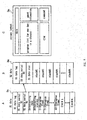
- the EPG data D EPG produced by the EPG editor 12 of the transmitter 2 consists of the information D PC relating to the programs of each broadcasting channel during several ten hours from current time (e.g., channel of program, broadcasting time, title, genre, program comments, and so on) (hereinafter, referred to as program content data), and the information D ML relating to the layout of screen for displaying a program list and the detailed information of a program (hereinafter, referred to as screen layout data).
- the program content data D PC hierarchically consists of: the data in which an information group representing program contents for each program is assigned to plural programs each having a broadcasting form such as for regular program, for rebroadcasting, for broadcasting at a key station, or for broadcasting at a local station (hereinafter, referred to as A1 data); the data in which only a particular information group which is common in a plurality of programs of the A1 data is arranged as a single program (hereinafter, referred to as A2 data); and the data which represents the detailed contents of the information groups consisting of respective programs of the A1 data and the A2 data (hereinafter, referred to as A3 data).
- the A1 data is possible to be changed depending on the broadcasting form, such as broadcasting year/month/date and the broadcasting starting time.
- the A2 data is a fixed information which is not changed depending on the broadcasting form, such as the program name, program detailed information, still pictures, sounds, moving pictures, and the names of guests.
- the A3 data is comparatively large sized data and detailed information, such as still pictures, sounds, moving pictures, a guide, the names of guests, broadcasting form, a category, and the name of broadcasting station.
- the same program is repeatedly broadcasted with an interval, so that the program information which changes when broadcasted repeatedly is set to as the A1 data, and the program information which does not change when broadcasted repeatedly is set to as the A2 data.
- the A1 data D A1 consists of several data relating to each program (for regular broadcasting F1 and for rebroadcasting F2), such as "A1 DATA TAG” representing the A1 data, "A1 DATA NO.” representing the serial number of the A1 data, "REF. A2 DATA NO.” representing the serial number for referring to the A2 data, "BROADCASTING Y/M/D”, “START TIME”, “END TIME”, "BROADCASTING STA.
- PROGRAM CATEGORY NO.” representing the number of the type of programs such as news, entertainment, and movie
- SUVB-CATEGORY NO.” representing the number of the type of programs such as news, entertainment, and movie
- BROADCASTING FORM NO.” representing the number of the form such as stereo, bilingual, and clear vision
- CM TAG NO.” representing the CM information.
- the A2 data D A2 comprises a program (standard program) F3 that the common data among the programs of the A1 data are collected and put in order, and consists of respective serial numbers for referring to the data of program name, program detailed information, still picture, sound, moving picture, and the name of guests, such as "A2 DATA TAG” representing the A2 data, "A2 DATA NO.” representing the serial number of the A2 data, "PROGRAM NAME”, “DETAILS NO.”, "STILL PICTURE NO.”, "SOUND NO.”, “MOVING PICTURE NO.”, "NUMBER OF GUESTS” "GUEST NAME NO.[0]",..., and “GUEST NAME NO.[N]”.
- program (standard program) F3 that the common data among the programs of the A1 data are collected and put in order, and consists of respective serial numbers for referring to the data of program name, program detailed information, still picture, sound, moving picture, and the name of guests, such as "A2 DATA TAG” representing the
- the A3 data D A3 consists of the data representing the detailed contents relating to still picture, sound, moving picture, guide, the name of guests, broadcasting form category, the name of broadcasting station, and CM, among the programs of the A1 data and A2 data.
- data F4 relating to the broadcasting station consists of "A3 BROADCASTING STA. TAG” representing the A3 data, "BROADCASTING STA. NO.”, and “BROADCASTING STA. NAME”.
- data F5 relating to category consists of "A3 CATEGORY TAG”, “CATEGORY NO.”, and “CATEGORY NAME”.
- data F6 relating to the broadcasting form consists of "A3 BROADCASTING FORM TAG”, “BROADCASTING FORM NO.”, and "BROADCASTING FORM NAME".
- Data F7 relating to guests consists of "A3 GUEST TAG”, “GUEST NO.”, “GUEST NAME”, “GUEST INFORMATION”, and “GUEST STILL PICTURE NO.”.
- Data F8 relating to the program detailed information consists of "A3 GUIDE TAG”, “DETAILS NO.”, and "DETAILS”.
- data F9 of still picture consists of "A3 PICTURE TAG”, “STILL PICTURE NO.”, and “STILL PICTURE DATA”.
- Sound data F10 consists of “A3 SOUND TAG”, “SOUND NO.”, and “SOUND DATA”.
- Moving picture data F11 consists of "A3 MOVIE TAG”, “MOVING PICTURE NO.”, and “MOVING PICTURE DATA”.
- data F12 relating to CM consists of "A3 CM TAG”, “DISPLAY POSITION”, “CM STILL PICTURE NO.”, “CM SOUND NO.”, “CM MOVING PICTURE NO.”, and "URL (Uniform Resource Locater)".
- the URL is the standards which is provided to prescribe means for accessing the information resource of Internet (e.g., www server) and the name of information resource.
- the EPG editor 12 firstly produces the A1 data D A1 of program for regular broadcasting F1 and the A1 data D A1 of program for rebroadcasting F2, based on the output management data D BC having the program information of " ⁇ ", and then produces the A2 data D A2 which is referred in common between these A1 data D A1 .
- the EPG editor 12 then produces the A3 data D A3 which is more detailed data referred by the A1 data D A1 and A2 data D A2 .
- the data F12 relating to CM of the A3 data D A3 is produced by the EPG editor 12 based on the commercial information D CM described above.
- the broadcasting wave S1 received by a parabolic antenna 20 is demodulated and compressive-decoded at an integrated receiver/decoder (IRD) 21.
- the resultant video/audio signal SV1 is output to a VCR (Video Cassette Recorder) 22 of the VHS system.
- VCR Video Cassette Recorder
- the VCR 22 records the video/audio signal SV1 in a video tape loaded inside, or outputs the video/audio signal SV1 from an output line as it is to a monitor device 23 to display it on the monitor.
- the command corresponding to the operation is converted into infrared ray signal IR to be output to the integrated receiver/decoder 21.
- the integrated receiver/decoder 21 executes various operations based on the command, the operations such as channel change, registering/reading user data, outputting control signal CONT to respective devices (the VCR 22, the VCR 25, the DVD 26, and the MD 27) which are connected to the integrated receiver/decoder 21.
- the control signal CONT is output to the VCR 22 through a control line.
- the VCR 22 When the VCR 22 is specified as a target to be controlled by the control signal CONT, the VCR 22 is controlled by the control signal CONT. On the other hand, when any of devices which are successively connected to the VCR 22 through the control line (the VCR 25 of 8mm system, the digital video disc (DVD) player 26, the mini disc (MD) player 27, and the monitor device 23) is specified, the VCR 22 outputs the control signal CONT as it is to the following VCR 25 of 8mm system.
- the VCR 22 outputs the control signal CONT as it is to the following VCR 25 of 8mm system.
- the VCR 25 determines the device specified by the control signal CONT. When the determined result is the VCR 25, the VCR 25 executes the operation specified by the control signal CONT. If the command is for reproducing a 8mm video tape loaded in the VCR 25 for example, the VCR 25 reproduces the video tape, so as to output the reproduced video signal SV3 to the monitor device 23 to display it.
- the VCR 25 records the video/audio signal SV1 input from the integrated receiver/decoder 21 through the VCR 22 of the VHS system and the monitor device 23.
- the VCR 25 outputs the control signal CONT as it is to the following DVD 26.
- the DVD 26 When receiving the control signal CONT, the DVD 26 determines the device specified by the control signal CONT. When the determined result is the DVD 26, the DVD 26 executes the operation specified by the control signal CONT. If the command is for reproducing an image and/or sound from a disc loaded in the DVD 26 for example, the DVD 26 reproduces the disc, so as to output video/audio signal SV4 to the monitor device 23 to display it. On the other hand, if the DVD 26 is not a target to be controlled by the control signal CONT, the DVD 26 outputs the control signal CONT to as it is the following MD 27.
- the MD 27 determines the device specified by the control signal CONT. When the determined result is the MD 27, the MD 27 executes the operation specified by the control signal CONT. If the command is for reproducing a disc loaded in the MD 27 for example, the MD 27 reproduces the disc, so as to output audio signal SV5 to the monitor device 23 to display that it can be listened.
- the MD 27 records the audio signal of the video/audio signal SV1 input from the integrated receiver/decoder 21 through the VCR 22 of the VHS system and the monitor device 23.
- the MD 27 outputs the control signal CONT as it is to the following monitor device 23. At this time, the monitor device 23 executes the operation specified by the control signal CONT.
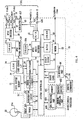
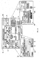
- the broadcasting wave received by a LNB (Low Noise Block Downconverter) 20A of the parabolic antenna 20 is supplied to a front end 30.
- the program guide information (EPG data) and so on are superimposed on the broadcasting wave in accordance with the prescribed format.
- the front end 30 is provided with a tuner 31, a demodulating circuit 32, and an error correcting circuit 33, and respective circuit parts are controlled by a system controller 44.
- the broadcasting wave received by the antenna 20 is supplied to the tuner 31.
- the tuner 31 performs a tuning processing in accordance with the control of the system controller 44.
- the output of the tuner 31 is supplied to the demodulating circuit 32 to be demodulated.
- the output of the demodulating circuit 32 is supplied to the error correcting circuit 33, in which an error is detected and corrected, and if necessary compensated.
- a key necessary to decode codes is stored together with the decoding program. Because the signal transmitted via a broadcasting satellite is coded, the key and the decoding processing are needed to decode the codes. Then, the key is read out from the CAM 34 through a card reader interface 35, and is supplied to a demultiplexer 36. The demultiplexter 36 uses the key to decode the coded signal.
- the demultiplexer 36 receives the signal output from the error correcting circuit 33 of the front end 30, and temporarily stores it in a data buffer memory 51 comprising a DRAM (Dynamic Random Access Memory) or a SRAM (Static Random Access Memory).
- the demultiplexer 36 suitably reads this, and supplies the video signal of the read signal to a MPEG video decoder 37 and supplies audio signal to a MPEG audio decoder 38.
- the MPEG video decoder 37 stores the digital video signal supplied from the demultiplexer 36 in a DRAM 37A to decode the video signal compressed by the MPEG system.
- the decoded video signal is supplied to a NTSC encoder 39, which is converted into luminance signal (Y), chroma signal (C), and composite signal (V) of the NTSC system.
- the luminance signal (Y) and the chroma signal (C) are output as S video signal through buffer amplifiers 40Y and 40C.
- the composite signal is output through a buffer amplifier 40V
- the MPEG audio decoder 38 stores the digital video signal supplied from the demultiplexer 36 in a DRAM 38A to decode the audio signal compressed by the MPEG system.
- the decoded audio signal is digital-to-analog converted in a D/A converter 41.
- the audio signal of left channel is output through a buffer amplifier 42L.
- the audio signal of right channel is output through a buffer amplifier 42R.
- a RF modulator 43 converts the composite signal output from the NTSC encoder 39 and the audio signal output from the D/A converter 41 into RF signal, and outputs it. Further, when the television (TV) mode is set, the RF modulator 43 passes through the television signal of the NTSC system input from other AV device such as a cable box, and outputs it to other device. In this embodiment, the video signal and audio signal are supplied to the VCR 22 through the AV line.
- the system controller 44 executes various processings in accordance with the programs stored in the ROM (Read Only Memory) 45. For instance, the system controller 44 controls the tuner 31, the demodulating circuit 32, and the error correcting circuit 33 which are provided in the front end 30.
- ROM Read Only Memory
- a predetermined command can be directly input by operating an operation button switch (not shown) of a front panel 47. Further, when the operation keys of the remote commander 24 are operated, the infrared ray signal is output from an IR sending part of the remote commander 24 and received by an IR receiving part 48, and then the received result is supplied to the system controller 44. Thereby, the remote commander 24 is operated so as to input a predetermined command to the system controller 44.
- the multiplexer 36 takes in the EPG data D EPG (which is temporarily stored in the buffer memory 51) excepting the MPEG video data and audio data supplied from the front end 30, and supplies it to a multimedia processor 46 through the system controller 44.
- the multimedia processor 46 comprises an EPG processing part 46A, a browser controlling part 46B, a memory 46C, and a graphic engine 46D.
- the multimedia processor 46 produces data for displaying a screen such as a program list, contains a browser software of Internet, and performs HTML (Hyper Text Markup Language) processing.
- the program guide information includes the information relating to programs of each broadcasting channel during a predetermined term from current time (e.g., still picture of program, channel, broadcasting time, title, and category).
- the program guide information is transmitted frequently, so that the latest EPG data is always maintained in a memory 46C of the multimedia processor 46.
- An EPG processing part 46A picks up necessary items of the A1 to A3 data D A1 to D A3 constituting the program content data D PC from the EPG data D EPG stored in the memory 46C so that they correspond to the layout of the display screen based on the screen layout data D ML , and produces the data D B of a predetermined format (hereinafter referred to as B data) (Fig. 3).
- the B data D B has two types of format and consists of the data D B1 and D B2 (hereinafter, referred to as B1 data and B2 data).
- the B2 data D B2 refers to the B1 data D B1 .
- the EPG processing part 46A refers to the program content data D PC , and based on the B1 data D B1 , the B2 data D B2 , and the screen layout data D ML , produces the display data D C (hereinafter, referred to as C data) (Fig. 3 described later) that various program detailed information are assigned to the layout of the screen for displaying the EPG data D EPC (hereinafter, referred to as EPG screen).
- the display data of the EPG screen produced in this way is written in the DRAM 37A with a bit map form.
- the display data written in the DRAM 37A is processed by the MPEG video decoder 37 to be displayed.
- the browser controlling part 46B creates bit map data of home page based on the HTML data transmitted from the www server on the Internet 5 through a modem 52 connected to a telephone line and the system controller 44, and writes it in the DRAM 37A.
- the display data written in the DRAM 37A is processed by the MPEG video decoder 37 to be displayed.
- the EPG processing part 46A and the browser controlling part 46B process the EPG screen and the bit map data of the home page, so that the EPG screen and the home page can be displayed and viewed.
- An EEPROM (Electrically Erasable programmable Read Only Memory) 50 appropriately stores data which is desired to be kept after a power supply is turned off, such as various setting data which is set by a user in various items on a menu screen (e.g., favorite channel data set by a user), and channel number received immediately before a predetermined operation is performed (the last channel).
- the system controller 44 makes a minimum number of circuits, such as the front end 30, the demultiplexer 36, and the data buffer memory 51, to be in the operable state, even if the power supply is turned off, and checks the current time from the time information included in the reception signal thereby controlling each circuit to execute a predetermined operation at a predetermined time. For instance, a timer automatic recording can be performed by operating with the external VCR.
- the system controller 44 controls the MPEG video decoder 37. More specifically, the system controller 44 creates a predetermined on-screen display data, and writes it in the on-screen display data area of the DRAM 37A of the MPEG video decoder 37 as bit map data. Thereby, predetermined characters, figures, images, and so on are appropriately output to the display screen 23A of the monitor device 23 to be displayed.
- OSD on-screen display
- a SRAM 49 is used as a work memory of the system controller 44.
- the modem 52 transfers data through the telephone line under the control of the system controller 44.
- a data processing procedure which creates the C data D C from the EPG data D EPG obtained by receiving the broadcasting wave S1 and performs a display and conversion processing such as the generation of bit map data of the EPG screen in the multimedia processor 46 shown in Fig. 6, is explained here.
- A1 data D A1 , A2 data D A2 , and A3 data D A3 which are stored in the memory 46C in the multimedia processor 46 through the parabolic antenna 20, the front end 30, the demultiplexer 36, and the system controller 44, necessary items are extracted by the EPG processing part 46A in accordance with the layout of display screen, to create B1 data D B1 and B2 data D B2 .
- Each data structure and data contents of the B1 data D B1 and B2 data D B2 are different depending on the layout of the EPG screen based on the screen layout data D ML .
- the layout of the EPG screen is to make a program list screen for displaying programs for one day in a predetermined channel, as shown in Fig. 7, based on the screen layout data D ML , program frames for 24-hours are set in the B1 data D B1 as shown in Fig. 7A.
- the B1 data D B1 consists of "B1 DATA TAG” representing B1 data, "B1 DATA SERIAL NO.” representing the serial number of the B1 data, “B2 DATA SERIAL NO.” representing the serial number of the B2 data corresponding to the B1 data, "BROADCASTING DATE”, “BROADCASTING STATION”, "0:00 PROGRAM FRAME", “0:10 PROGRAM FRAME”, ..., “23:50 PROGRAM FRAME” representing program frames set for every predetermined time, and "CM#1" to "CM#K".
- the CM tag numbers corresponding to respective program columns of a program list are, assigned to the CM#1 and CM#k in this case.
- the B2 data D B2 is data obtained by referring the B1 data D B1 , and as shown in Fig. 7B, B2 data D B2 consists of "B2 DATA TAG” representing B2 data, "B2 DATA SERIAL NO.” representing the serial number of the B2 data, "B2 DATA SIZE” representing the size of the B2 data, and "STACK #1" to "STACK #N” in which the serial number of A1 data is written.
- the serial number of the A1 data of the program list corresponding to each time is input in each of the stack #1 to #N for example.
- the EPG processing part 46A searches a program for displaying the program detailed information with being classified by category, and inputs the serial number of the A1 data corresponding to a predetermined category in each stack
- the B1 data D B1 consists of "B1 DATA TAG” representing B1 data, "B1 DATA SERIAL NO.” representing the serial number of the B1 data, "B2 DATA SERIAL NO.” representing the serial number of the B2 data corresponding to the B1 data, "CATEGORY”, “PAGE”, "DETAILED INFORMATION #1” to "DETAILED INFORMATION #6", and "CM#1" to "CM#6".
- the CM information corresponding to the program detailed information #1 to #6 are assigned to the CM#1 and CM#6 in this case. While, the B2 data D B2 consists of the same format (Fig. 7B) as that of the program list screen described above (Fig. 8B).
- the EPG processing part 46A creates the C data (display data) D C .
- the C data D C refers the A1 data D A1 , the A2 data D A2 , and the A3 data D A3 through the B1 data D B1 and the B2 data D B2 .
- the C data D C created in this way is stored in the DRAM 37A as bit map data of the EPG screen, and is read out by the MPEG video decoder 37 described above to be displayed on the EPG screen of the monitor device 23.
- a standard screen layout data D ML ' previously stored in a memory of the multimedia processor 46 may be referred in addition to the transmitted screen layout data D ML (Fig. 3).
- Fig. 9 shows a data referring process to create the C data D c .
- an arrow in the figure denotes the direction for referring data.
- the A3 data D A3 is referred by the A1 data D A1 and the A2 data D A2
- the A2 data D A2 is referred by the A1 data D A1
- the A1 data D A1 is referred by the B2 data D B2
- the B2 data D B2 is referred by the B1 data D B1
- the B1 data D B1 and the screen layout data D ML are referred by the C data D c . Therefore, the C data D C can refer the A3 data D A3 , through the B1 data D B1 , the B2 data D B2 , the A1 data D A1 , and the A2 data D A2 .
- a user operates the remote commander 24 to select the channel of the information providing program representing the electronic program guide information (EPG data D EPG ) among from a plurality of channels which can be displayed on the display screen 23A of the monitor device 23, so that it can be displayed on the display screen 23A.
- EPG data D EPG electronic program guide information
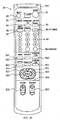
- Fig. 10 shows the construction of the remote commander 24.
- An IR signal sending part 24A for sending IR signal corresponding to each key operation described later is provided on the upper portion of the remote commander 24.
- the remote commander 24 provides with a power supply key K1 and a television power supply key K2 for turning on or off the power source of the integrated receiver/decoder 21 and the monitor device 23 respectively; a mute key K3 for muting sounds or canceling the mute, switch keys K4 and K5 for switching the function of the remote commander 24 between the integrated receiver/decoder 21 and the monitor device 23, an input changing key K6 for changing the input to the integrated receiver/decoder 21, a screen display key K7 for displaying a channel number and so on (which includes a station logo and title) on the screen 23A of the monitor device 23 or erasing the display, a bilingual key K8 for changing a voice output from the monitor device 23 into main voice, sub-voice, or main+sub-voice (foreign language, Japanese, or foreign language and
- the remote commander 24 further provides with a menu key K11 for displaying a menu screen to set various items of the integrated receiver/decoder 21 on the monitor device 23, a program details key K12 for displaying a program detailed information of the electronic program guide information, a guide channel previous notice key K13 for displaying the previous notice of programs which will be broadcasted in the future, a favorite list key K14 for displaying the station logo list of channel which has been previously registered by a user, a program list key K15 for displaying the program list based on the electronic program guide, a reserve list key K16 for displaying reserved programs, cursor keys K17 to K20 for transferring a cursor displayed on the screen 23A of the monitor device 23 up and down, left and right (for operating the direction), a select (enter) key K21 for selecting and deciding a frame to which a cursor is transferred by operation of the cursor keys K17 to K20, and a volume up and down key K22 and a channel up and down key K23 for increasing or decreasing volume or channel number.
- the system controller 44 can display the electronic program guide on the display screen 23A of the monitor device 23 in accordance with the display processing procedure RT1 of the electronic program guide shown in Fig. 11.
- the system controller 44 starts the display processing procedure RT1 at step SPO, and judges at next step SP1 whether or not the program list key K15 of the remote commander 24 is selected.
- step SP1 the system controller 44 proceeds to step SP2 to store the EPG data D EPG (that is, program content data D PC and screen layout data D ML ) supplied to the integrated receiver/decoder 21 in the memory 46C of the multimedia processor 46, and then proceeds to step SP3.
- EPG data D EPG that is, program content data D PC and screen layout data D ML
- step SP1 when a negative result is obtained at step SP1, the system controller 44 returns to step SP1 again to wait until the program list key K15 of the remote commander 24 is selected.
- step SP3 the EPG processing part 46A proceeds to step SP3 under the control of the remote commander 44, to extract necessary items for the layout of display screen based on the screen layout data D ML among from the A1 to A3 data D A1 to D A3 constituting the program content data D PC .
- the extracted data is used to create the B data D B , and then a processing proceeds to step SP4.
- the EPG processing part 46A judges whether or not the layout of the display screen based on the screen layout data D ML includes the CM display area.
- step SP4 the EPG processing part 46A proceeds to step SP5 to refer the data F12 (Fig. 4C) relating to CM among from the A3 data D A3 constituting the program content data D PC , and then proceeds to step SP6.
- step SP4 when a negative result is obtained at step SP4, the system controller 44 proceeds to step SP6 as it is.
- the system controller 44 creates the C data D C based on the B data D B and the screen layout data D ML at step SP6, and creates bit map data of the EPG screen.
- the created bit map data is stored in the DRAM 37A at step SP7 and displayed by the MPEG video decoder 37. After that, the system controller 44 proceeds to step SP8 to terminate the display processing procedure RT1.
- the EPG screen M1 e.g. the screen shown in Fig. 12, can be displayed on the display screen 23A of the monitor device 23.
- the EPG screen M1 mainly has a program guide area A 1 , an operation setting area A 2 , and a CM display area A 3 .
- the program guide area A 1 the guide columns of television programs in various time zones are displayed for every broadcasting stations, and the program detailed screen of a predetermined form is hierarchically set in each program.
- the operation menu area A 2 the operation menus of "Search”, “Reserve”, “Set”, and “Return” are displayed, and the operation screen of a predetermined form is hierarchically set in each operation menu.
- CM display area A 3 the image of a program displayed at each guide column constituting the program guide area A 1 and CM provided from a CM sponsor who contracts in advertisement are selectively displayed.
- CM TAG NO.” corresponding to "START TIME” (7:00pm), "END TIME” (8:55pm), and "BROADCASTING STA. NO.” (channel 6) of the A1 data D A1 .
- the still picture data F9 of the A3 data D A3 is referred by "CM STILL PICTURE NO.” of the data F12 relating to CM, and resulting that the still picture data corresponding to "CM STILL PICTURE No.” is displayed in the CM display area A 3 of the EPG screen M1.
- the A2 data D A2 is referred by the reference A2 data number of the A1 data D A1 .
- the still picture data F9 of the A3 data D A3 is referred by the still picture number of the A2 data D A2 , and resulting that the still picture is displayed in the CM display area A 3 of the EPG screen M1.
- the moving picture is same as this case.
- the program details screen M2 showing the details of the selected guide column is displayed.
- the program detailed information data F8 of the A3 data D A3 is referred by "PROGRAM DETAILED INFORMATION NO.” of the A2 data D A2
- the still picture data F9 of the A3 data D A3 is referred by "STILL PICTURE NO.” regarding the program detailed information.
- the data F7 relating to guest of the A3 data D A3 is referred by "GUEST NAME NO.[0]", to "GUEST NAME NO.[N]" of the A2 data D A2 .
- the CM display area B 1 is displayed at a predetermined layout position of the program details screen M2, and in the CM display area B 1 , the CM corresponding to the selected guide column is displayed.
- the data F12 relating to CM of the A3 data D A3 is referred by the same "CM TAG NO.” as the CM display area A 3 on the EPG screen M1, and at the same time, the still picture data F9 of the A3 data D A3 is referred by "CM STILL PICTURE NO.” of the data F12 relating to CM.
- the CM display area C 1 is displayed at a predetermined layout position on the operation screen M3, and in the CM display area C 1 , the CM in accordance with the guide column searched by the search operation is displayed.
- CMs are displayed in the CM display areas A 3 of the EPG screen M1, the CM display areas B 1 of the program details screen M2, and the CM display areas C 1 of the operation screen M3 respectively.
- a home page showing the detailed information of the CM displayed on the CM display area A 3 , B 1 , or C 1 is obtained from the www server on the Internet 5, so as to display it on the display screen 23A of the monitor device 23.
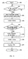
- the system controller 44 displays the home page showing the detailed information of the CM displayed in the CM display area A 3 , B 1 , or C 1 on the display screen 23A of the monitor device 23 in accordance with the display processing procedure RT2 of the CM information shown in Fig. 13.
- the cursor keys K17 to K20 of the remote commander 24 are operated, in the condition that the EPG screen M1, the program details screen M2, or the operation screen M3 is displayed on the display screen 23A of the monitor device 23, to transfer a cursor to the CM display area A 3 , B 1 , or C 1 , the system controller 44 starts the display processing procedure RT2 at step SP10, and judges whether or not the select key K21 of the remote commander 24 is clicked at step SP11.
- step SP11 the system controller 44 proceeds to step SP12 to read out the URL information corresponding to the CM displayed on the CM display area A 3 , B 1 , or C 1 from the data F12 of the A3 data D A3 (Fig. 4C) among from the program content data D PC which are stored in the memory 46C of the multimedia processor 46.
- step SP11 if a negative result is obtained at step SP11, the system controller 44 returns to step SP11 again to wait until the select key K21 of the remote commander 24 is clicked.
- step SP13 the system controller 44 proceeds to step SP13 to start up the browser controlling part 46B in the multimedia processor 46.
- the started up browser controller part 46B accesses a page corresponding to the specified URL information through a modem 52.
- the HTML data of the home page obtained from a desired CM sponsor's terminal device 6 is displayed by the browser controlling part 46B, and stored in the DRAM 37A with a bit map form (step SP14).
- bit map data stored in the DRAM 37A is read out by the MPEG video decoder 37 and displayed on the display screen 23A.
- a display method as shown in Fig. 14A to 14C, there are three kinds of display methods, whole screen display, two-divided display, and overlay display (the EPG screen M1 can be viewed transparently), which is selected by a user. After that, a processing proceeds to step SP15 to terminate the display processing procedure RT2.
- the CM of a sponsor providing a program in which a user is interested i.e., a program with which the cursor is matched
- the CM of a sponsor providing the program is displayed in the CM display area A 3 of the EPG screen M1
- the CM of a sponsor providing the program is displayed also in the CM display area B 1 of the program details screen M2 which is displayed on the display screen 23A.
- the CM of a sponsor providing the program to which a user pays attention is displayed on the EPG screen M1 and the program details screen M2 by selecting the program by the user.
- the remote commander 24 When the user operates the remote commander 24 to match a cursor onto the CM display area A 3 , B 1 , or C 1 and clicks the select key K21, the home page showing the detailed information of the CM can be displayed.
- a user can get a desired information among from the information transmitted via a digital broadcasting through an Internet at any time. As a result, it can be prevented that the construction of the receiving apparatus is magnified and complicated because the information transmitted via the digital broadcasting must be all stored, and the information transmitted via the digital broadcasting is unnecessary to be increased.
- a user at the time of searching a program using the EPG screen, a user can view the CM of the sponsor providing an interesting program, and simultaneously, the detailed information of a desired CM selected by user can be easily obtained through the Internet if necessary.
- this invention has dealt with the case where this invention is applied to a system for transmitting a television broadcasting by a broadcasting wave from the transmitting apparatus 2 in the broadcasting station via the satellite transponder 3.
- this invention is not only limited to this, but it can be transmitted via a ground wave circuit or a ground wire circuit from the transmitting apparatus 2 in the broadcasting station.
- the program guide display device 60 shown in Fig. 15 is connected to a television receiving apparatus (not shown) through the television line 61, and the information recording medium 62 such as a DVD-ROM and a CD-ROM in which the EPG data D EPG is recorded is loaded in the program guide display device 60 to read this, so that the same screen as the above-mentioned information providing program (EPG screen M1, the program details screen M2 or the operation screen M3) can be displayed on the touch panel 60A.
- a telephone circuit 63 is connected to the program guide display device 60 via the www server and Internet 5 similar to the above described case.
- the embodiment described above has dealt with the case where various GMs are only displayed in the CM display area A 3 , B 1 , or C 1 which is displayed on the EPG screen M1, the program details screen M2, or the operation screen M3.
- this invention is not only limited to this, but the corresponding URL information also can be displayed by characters in the CM display area A 3 , B 1 , or C 1 in addition to the CM.
- CMs are only displayed in the CM display area A 3 , B 1 , or C 1 which is displayed on the EPG screen M1, the program details screen M2, or the operation screen M3.
- this invention is not only limited to this, but as shown in Fig. 12, a cursor is matched with the CM display area A 3 , B 1 , or C 1 so as to play a sound corresponding to the CM from a sound output means (speaker S p ) provided in the monitor device 23.
- the data F12 relating to the CM of the A3 data D A3 is referred by "CM TAG NO.” corresponding to "START TIME” (7:00pm), "END TIME” (8:55pm), and "BROADCASTING STA. NO.” (channel 6) of the A1 data D A1 .
- the sound data F10 of the A3 data D A3 is referred by "CM SOUND NO.” of the data F12 relating to the CM, and resulting that the sound corresponding to "CM SOUND NO.” is played from the speaker S p .
- CM STILL PICTURE NO.” of the data F12 relating to the CM refers the still picture data F9 of the A3 data D A3 , so that the still picture data corresponding to "CM STILL PICTURE NO.” is displayed in the CM display area A 3 on the EPG screen M1.
- this invention is not only limited to this, but "CM MOVING PICTURE NO.” of the data F12 relating to the CM refers the moving picture data F11 of the A3 data D A3 , so that the moving picture data corresponding to "CM MOVING PICTURE NO.” can be displayed in the CM display area A, on the EPG screen M1.
- the embodiment described above has dealt with the case where the CM provided by a CM sponsor who contracts in advertisement with a program displayed at each guide column constituting the program guide area A 1 is selectively displayed in the CM display area A 3 on the EPG screen M1.
- this invention is not only limited to this, but a plurality of CMs can be successively displayed for a single program.
- a plurality of CMs for a single program can be successively displayed in the CM display area B 1 of the program details screen M2 and the CM display area C 1 of the operation screen M3.
- CM TAG NO.” a plurality of "CM TAG NO.” are put in the A1 data D A1 and these "CM TAG NO.” successively refers the data F12 relating to the CM of the A3 data D A3 , a plurality of CMs for a single program can be successively displayed with being shifted temporally.
- the embodiment described above has dealt with the case where the commercial information (CM) of the sponsor providing a corresponding program is applied as the distribution information displayed with the information of each program.
- CM commercial information
- this invention is not only limited to this, but other distribution information can be widely applied if it is an information providing the more detailed information and latest information of corresponding program, such as the latest information of "automobiles for race” in the "car race” program.
- CM information distribution information displayed with each program information (EPG data) which is displayed on the display screen 23A of the monitor device 23.
- this invention is not only limited to this, but a desired distribution information can be specified by selecting and pressing the panel plane of the touch panel by a user. Also, a desired distribution information can be specified by transferring a cursor on the display screen 23A and clicks it by a user.
- the embodiment described above has dealt with the case where the EPG data D EPG is transmitted by using the MPEG2 system.
- this invention is not only limited to this, but the EPG data D EPG can be transmitted by using other image compression techniques such as the MPEG1 and JPEG.
- the embodiment described above has dealt with the case where the www server is used as a computer server for providing the CM detailed information.
- this invention is not only limited to this, but other various servers such as a mail server having a function of sending and receiving a mail, a news server having a function of exchanging information by a meeting or a notice board, and a FTP server having a function of sending a file.
- the embodiment described above has dealt with the case where the integrated receiver/decoder 21 and the computer server are connected each other through a telephone line.
- this invention is not only limited to this, but data can be sent and received via a satellite transponder for example other than the telephone line.
- the embodiment described above has dealt with the case where the Internet 5 is used as a computer network.
- this invention is not only limited to this, but is widely applicable to other various communication networks such as a computer network service.
- the address information for reading the detailed information of the computer server which provides the detailed information of the distribution information displayed on a predetermined display screen together with a single program or plural programs is transmitted with each program information, so as to realize an information transmitting method and a television broadcasting receiving apparatus which easily obtain, if necessary, the detailed information of the distribution information transmitted with each program information without storage of it at a receiving side.
- this invention can be utilized in the case where the information is distributed by using a satellite broadcasting system, a ground wave broadcasting system, or a wire broadcasting system.
Abstract
Description
- The present invention relates to an information transmitting method and a television broadcasting receiving apparatus, and more particularly, applicable to a program broadcasting system for guiding and displaying information relating to each program, when a viewer selects a necessary program among from a large number of television programs transmitted through a satellite broadcasting.
- Recently, in a satellite broadcasting system for sending television programs to viewers via a broadcasting satellite, a method for compressive-encoding and multiplexing the program data of plural channels by using the MPEG2 (Moving Picture Image Coding Experts Group Phase 2) and transmitting it has been proposed. Such digital transmitting method can transmit a vast of programs at the same time, thereby increasing the number of programs a viewer can select.
- The program data encoded and multiplexed by the MPEG2 is multiplexed with program guide information, and transmitted. The program guide information is displayed at a receiver in the form like a television program guide column on a newspaper, for example.
- The program guide information is repeatedly transmitted so as to be received at a receiver side at any time, and as the number of programs increases, the data size becomes larger. Also, the program guide information includes the information of programs which will be broadcasted in the future, and the data size changes depending on the condition that the program guide information of how many days ahead is transmitted. To display such a large number of data at a receiving side instantly, it can be considered that a recording medium such as a hard disk is provided in the receiver to successively store the transmitted program data.
- However, if a recording medium such as a hard disk is provided in a receiving side, the whole construction of a receiver becomes complicated and large, and there is a problem that it costs the viewer. When the size of data to be transmitted becomes larger, the number of times the data can be repeatedly transmitted is reduced at a transmitting side. As a result, the receiving side can not display a program guide instantly, so that the size of data to be transmitted as program guide information is necessarily limited within the minimum. Thereby, even if a user wants to know the detailed program information more, the information is not transmitted, or it takes a long time to receive it. Moreover, the information which is not directly related to a program, such as a commercial (CM), is not transmitted in detail.
- This invention is to solve the problems described above and to provide an information transmitting method and a television broadcasting receiving apparatus which can easily obtain, if necessary, distribution information transmitted together with program data without being stored at a receiving side.
- To solve the above problems, according to this invention, address information for reading the detailed information from a computer server which provides the detailed information of the distribution information displayed together with the information of a program or plural programs on a predetermined display screen is transmitted together with the information of each program.
- Further, according to embodiments of this invention, there provides specifying means for specifying the distribution information displayed together with the information of a program or plural programs on a predetermined display screen, and access means for accessing a computer server which provides the detailed information of the distribution information specified by the specifying means through a computer network and taking in the detailed information from the computer server, based on the address information transmitted together with the information of each program. The detailed information taken in by the access means is displayed on the display screen.
- As a result, this can prevent the receiving apparatus from being large and complicated construction due to the storage of all the detailed information of the distribution information transmitted together with the information of each program, and avoid the uneconomical method that the detailed information of the distribution information which is interested by a user is transmitted by using a television broadcasting.
-
- Fig. 1 is a block diagram showing the whole construction of a program broadcasting system according to the present invention;
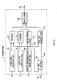
- Fig. 2 is a block diagram showing the construction of a transmitter according to the present invention;
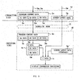
- Fig. 3 is a schematic diagram explaining the structure of EPG data;
- Fig. 4 is a schematic diagram explaining the structure of program content data of the EPG data in Fig. 3;
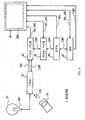
- Fig. 5 is a block diagram showing the construction of a receiver;
- Fig. 6 is a block diagram showing the construction of a receiver/decoder provided in the receiver in Fig. 5;
- Fig. 7 are schematic diagrams showing B data and the screen layout;
- Fig. 8 are schematic diagrams showing B data and the screen layout;
- Fig. 9 is a schematic diagram explaining a data reference procedure to create C data.
- Fig. 10 is a plain diagram showing the outward construction of a remote commander;
- Fig. 11 is a flowchart showing the procedure for displaying EPG;
- Fig. 12 is a schematic diagram explaining an information providing program displayed on a display screen of a monitor device;
- Fig. 13 is a flowchart showing the procedure for displaying CM information;
- Fig. 14 are schematic diagrams showing display examples of home page; and
- Fig. 15 is a schematically perspective view showing the outward construction of a program guide display device according to other embodiment.
-
- Hereinafter, the embodiment of this invention will be described in details referring to the drawings.
- In Fig. 1, 1 shows a program broadcasting system as a whole. In a broadcasting station, various television programs are produced and various commercials (CM) are produced based on the commercial information provided from each CM sponsor in accordance with an advertisement contract with a plurality of CM sponsors. Further, in the broadcasting station, the commercial information provided from a plurality of sponsors is superimposed on a program guide in addition to usual television programs.
- A
transmitter 2 provided in the broadcasting station transmits television programs and CM video audio data (hereinafter, referred to as program data and CM data, respectively) which comprise plural channels, by transport streams prescribed by the MPEG2 systems, and at the same time transmits program guide information (hereinafter, referred to as EPG (Electronic Program Guide) data). - in the MPEG2 systems, a large number of individual transport streams are time-division-multiplied by a transport packet of comparatively short transmission unit, so as to transmit the program information of multichannel.
- The information for identifying the contents of packet data is assigned to the header portion of the transport packet. A receiver which receives the broadcasting wave separates a packet necessary to decode by the information for identifying the contents.
- In each of
receivers 4, the transport packets of program data, CM data, and EPG data of a desired channel are respectively picked up from the multiplexed transport stream which is based on the received broadcasting wave S1. Based on the video audio data stored in these transport packets, a processing for decoding/displaying a program and CM and a processing for displaying a program guide are performed. - Here, each CM sponsor and broadcasting station (Fig. 1) have
terminal devices terminal devices - Also, each of the
receivers receivers - As shown in Fig. 2, the
transmitter 2 in the broadcasting station produces output management data comprising broadcasting time information, program ID, and so on in an output managementdata producing part 10, and supplies this data to amain control part 11 and anEPG editor 12 as output management data DBC. Themain control part 11 generates timing control signal STM which represents a timing of outputting each program, based on the output management data DBC, and outputs this signal toencoders EPG sub-control part 15 to control the operation of outputting data in each circuit. - A video data producing part 16 and an audio data producing part 17 produce video data DV and audio data DA which consist of various program data and CM data, which are compressive-encoded by the MPEG2 through the
encoders multiplexer 18. - Further, the
EPG editor 12 takes in the output management data DBC and the commercial information DCM provided from plural CM sponsors (Fig. 1), and based on this data, produces EPG data DEPG to supply this to theEPG sub-control part 15. In theEPG sub-control part 15, the supplied EPG data DEPG is synchronized with the timing control signal STM to supply this to themultiplexer 18. - The
multiplexer 18 time-division-multiplies the encoded video data Dv, audio data DA, and EPG data DEPG, so that these data are transmitted as a transport stream TS. - Here, as shown in Fig. 3, the EPG data DEPG produced by the
EPG editor 12 of thetransmitter 2 consists of the information DPC relating to the programs of each broadcasting channel during several ten hours from current time (e.g., channel of program, broadcasting time, title, genre, program comments, and so on) (hereinafter, referred to as program content data), and the information DML relating to the layout of screen for displaying a program list and the detailed information of a program (hereinafter, referred to as screen layout data). - The program content data DPC hierarchically consists of: the data in which an information group representing program contents for each program is assigned to plural programs each having a broadcasting form such as for regular program, for rebroadcasting, for broadcasting at a key station, or for broadcasting at a local station (hereinafter, referred to as A1 data); the data in which only a particular information group which is common in a plurality of programs of the A1 data is arranged as a single program (hereinafter, referred to as A2 data); and the data which represents the detailed contents of the information groups consisting of respective programs of the A1 data and the A2 data (hereinafter, referred to as A3 data). Here, the A1 data is possible to be changed depending on the broadcasting form, such as broadcasting year/month/date and the broadcasting starting time. The A2 data is a fixed information which is not changed depending on the broadcasting form, such as the program name, program detailed information, still pictures, sounds, moving pictures, and the names of guests. The A3 data is comparatively large sized data and detailed information, such as still pictures, sounds, moving pictures, a guide, the names of guests, broadcasting form, a category, and the name of broadcasting station. In the case of the multichannel broadcasting such as a digital satellite broadcasting, the same program is repeatedly broadcasted with an interval, so that the program information which changes when broadcasted repeatedly is set to as the A1 data, and the program information which does not change when broadcasted repeatedly is set to as the A2 data.
- In details, as shown in Fig. 4A, the A1 data DA1 consists of several data relating to each program (for regular broadcasting F1 and for rebroadcasting F2), such as "A1 DATA TAG" representing the A1 data, "A1 DATA NO." representing the serial number of the A1 data, "REF. A2 DATA NO." representing the serial number for referring to the A2 data, "BROADCASTING Y/M/D", "START TIME", "END TIME", "BROADCASTING STA. NO.", "PROGRAM CATEGORY NO." representing the number of the type of programs such as news, entertainment, and movie, "SUB-CATEGORY NO.", "BROADCASTING FORM NO." representing the number of the form such as stereo, bilingual, and clear vision, and "CM TAG NO." representing the CM information.
- Further, as shown in Fig. 4B, the A2 data DA2 comprises a program (standard program) F3 that the common data among the programs of the A1 data are collected and put in order, and consists of respective serial numbers for referring to the data of program name, program detailed information, still picture, sound, moving picture, and the name of guests, such as "A2 DATA TAG" representing the A2 data, "A2 DATA NO." representing the serial number of the A2 data, "PROGRAM NAME", "DETAILS NO.", "STILL PICTURE NO.", "SOUND NO.", "MOVING PICTURE NO.", "NUMBER OF GUESTS" "GUEST NAME NO.[0]",..., and "GUEST NAME NO.[N]".
- Further, as shown in Fig. 4C, the A3 data DA3 consists of the data representing the detailed contents relating to still picture, sound, moving picture, guide, the name of guests, broadcasting form category, the name of broadcasting station, and CM, among the programs of the A1 data and A2 data.
- For example, data F4 relating to the broadcasting station consists of "A3 BROADCASTING STA. TAG" representing the A3 data, "BROADCASTING STA. NO.", and "BROADCASTING STA. NAME". Further, data F5 relating to category consists of "A3 CATEGORY TAG", "CATEGORY NO.", and "CATEGORY NAME". Furthermore, data F6 relating to the broadcasting form consists of "A3 BROADCASTING FORM TAG", "BROADCASTING FORM NO.", and "BROADCASTING FORM NAME". Data F7 relating to guests consists of "A3 GUEST TAG", "GUEST NO.", "GUEST NAME", "GUEST INFORMATION", and "GUEST STILL PICTURE NO.". Data F8 relating to the program detailed information consists of "A3 GUIDE TAG", "DETAILS NO.", and "DETAILS".
- Also, data F9 of still picture consists of "A3 PICTURE TAG", "STILL PICTURE NO.", and "STILL PICTURE DATA". Sound data F10 consists of "A3 SOUND TAG", "SOUND NO.", and "SOUND DATA". Moving picture data F11 consists of "A3 MOVIE TAG", "MOVING PICTURE NO.", and "MOVING PICTURE DATA".
- Furthermore, data F12 relating to CM consists of "A3 CM TAG", "DISPLAY POSITION", "CM STILL PICTURE NO.", "CM SOUND NO.", "CM MOVING PICTURE NO.", and "URL (Uniform Resource Locater)". The URL is the standards which is provided to prescribe means for accessing the information resource of Internet (e.g., www server) and the name of information resource.
- Here is the case where the program "○○○○" is practically broadcasted at 12:00pm, and is rebroadcasted at 17:00pm. The
EPG editor 12 firstly produces the A1 data DA1 of program for regular broadcasting F1 and the A1 data DA1 of program for rebroadcasting F2, based on the output management data DBC having the program information of "○○○○", and then produces the A2 data DA2 which is referred in common between these A1 data DA1. TheEPG editor 12 then produces the A3 data DA3 which is more detailed data referred by the A1 data DA1 and A2 data DA2. The data F12 relating to CM of the A3 data DA3 is produced by theEPG editor 12 based on the commercial information DCM described above. - In the
receiver 4 in Fig. 5, the broadcasting wave S1 received by aparabolic antenna 20 is demodulated and compressive-decoded at an integrated receiver/decoder (IRD) 21. The resultant video/audio signal SV1 is output to a VCR (Video Cassette Recorder) 22 of the VHS system. - The
VCR 22 records the video/audio signal SV1 in a video tape loaded inside, or outputs the video/audio signal SV1 from an output line as it is to amonitor device 23 to display it on the monitor. - When a viewer operates a
remote commander 24, the command corresponding to the operation is converted into infrared ray signal IR to be output to the integrated receiver/decoder 21. The integrated receiver/decoder 21 executes various operations based on the command, the operations such as channel change, registering/reading user data, outputting control signal CONT to respective devices (theVCR 22, theVCR 25, theDVD 26, and the MD 27) which are connected to the integrated receiver/decoder 21. The control signal CONT is output to theVCR 22 through a control line. - When the
VCR 22 is specified as a target to be controlled by the control signal CONT, theVCR 22 is controlled by the control signal CONT. On the other hand, when any of devices which are successively connected to theVCR 22 through the control line (theVCR 25 of 8mm system, the digital video disc (DVD)player 26, the mini disc (MD)player 27, and the monitor device 23) is specified, theVCR 22 outputs the control signal CONT as it is to the followingVCR 25 of 8mm system. - When receiving the control signal CONT, the
VCR 25 determines the device specified by the control signal CONT. When the determined result is theVCR 25, theVCR 25 executes the operation specified by the control signal CONT. If the command is for reproducing a 8mm video tape loaded in theVCR 25 for example, theVCR 25 reproduces the video tape, so as to output the reproduced video signal SV3 to themonitor device 23 to display it. - Further, if the command of the control signal CONT is for recording, at the
VCR 25, the broadcasting signal (video/audio signal SV1) received and decoded by the integrated receiver/decoder 21, theVCR 25 records the video/audio signal SV1 input from the integrated receiver/decoder 21 through theVCR 22 of the VHS system and themonitor device 23. On the other hand, if theVCR 25 is not a target to be controlled by the control signal CONT, theVCR 25 outputs the control signal CONT as it is to the followingDVD 26. - When receiving the control signal CONT, the
DVD 26 determines the device specified by the control signal CONT. When the determined result is theDVD 26, theDVD 26 executes the operation specified by the control signal CONT. If the command is for reproducing an image and/or sound from a disc loaded in theDVD 26 for example, theDVD 26 reproduces the disc, so as to output video/audio signal SV4 to themonitor device 23 to display it. On the other hand, if theDVD 26 is not a target to be controlled by the control signal CONT, theDVD 26 outputs the control signal CONT to as it is the followingMD 27. - When receiving the control signal CONT, the
MD 27 determines the device specified by the control signal CONT. When the determined result is theMD 27, theMD 27 executes the operation specified by the control signal CONT. If the command is for reproducing a disc loaded in theMD 27 for example, theMD 27 reproduces the disc, so as to output audio signal SV5 to themonitor device 23 to display that it can be listened. - Also, if the command of the control signal CONT is for recording, at the
MD 27, the broadcasting signal (video/audio signal SV1) received and decoded by the integrated receiver/decoder 21, theMD 27 records the audio signal of the video/audio signal SV1 input from the integrated receiver/decoder 21 through theVCR 22 of the VHS system and themonitor device 23. On the other hand, if theMD 27 is not a target to be controlled by the control signal CONT, theMD 27 outputs the control signal CONT as it is to the followingmonitor device 23. At this time, themonitor device 23 executes the operation specified by the control signal CONT. - As shown in Fig. 6, in the integrated receiver/
decoder 21, the broadcasting wave received by a LNB (Low Noise Block Downconverter) 20A of theparabolic antenna 20 is supplied to afront end 30. Note that the program guide information (EPG data) and so on are superimposed on the broadcasting wave in accordance with the prescribed format. - The
front end 30 is provided with atuner 31, ademodulating circuit 32, and anerror correcting circuit 33, and respective circuit parts are controlled by asystem controller 44. The broadcasting wave received by theantenna 20 is supplied to thetuner 31. Thetuner 31 performs a tuning processing in accordance with the control of thesystem controller 44. The output of thetuner 31 is supplied to thedemodulating circuit 32 to be demodulated. The output of thedemodulating circuit 32 is supplied to theerror correcting circuit 33, in which an error is detected and corrected, and if necessary compensated. - In a CAM (Conditional Access Module) 34 comprising a CPU and an IC card comprising a ROM and a RAM, a key necessary to decode codes is stored together with the decoding program. Because the signal transmitted via a broadcasting satellite is coded, the key and the decoding processing are needed to decode the codes. Then, the key is read out from the
CAM 34 through acard reader interface 35, and is supplied to ademultiplexer 36. Thedemultiplexter 36 uses the key to decode the coded signal. - The
demultiplexer 36 receives the signal output from theerror correcting circuit 33 of thefront end 30, and temporarily stores it in adata buffer memory 51 comprising a DRAM (Dynamic Random Access Memory) or a SRAM (Static Random Access Memory). Thedemultiplexer 36 suitably reads this, and supplies the video signal of the read signal to aMPEG video decoder 37 and supplies audio signal to aMPEG audio decoder 38. - The
MPEG video decoder 37 stores the digital video signal supplied from thedemultiplexer 36 in aDRAM 37A to decode the video signal compressed by the MPEG system. The decoded video signal is supplied to aNTSC encoder 39, which is converted into luminance signal (Y), chroma signal (C), and composite signal (V) of the NTSC system. the luminance signal (Y) and the chroma signal (C) are output as S video signal throughbuffer amplifiers 40Y and 40C. The composite signal is output through abuffer amplifier 40V - The
MPEG audio decoder 38 stores the digital video signal supplied from thedemultiplexer 36 in aDRAM 38A to decode the audio signal compressed by the MPEG system. The decoded audio signal is digital-to-analog converted in a D/A converter 41. The audio signal of left channel is output through abuffer amplifier 42L. The audio signal of right channel is output through abuffer amplifier 42R. - A
RF modulator 43 converts the composite signal output from theNTSC encoder 39 and the audio signal output from the D/A converter 41 into RF signal, and outputs it. Further, when the television (TV) mode is set, theRF modulator 43 passes through the television signal of the NTSC system input from other AV device such as a cable box, and outputs it to other device. In this embodiment, the video signal and audio signal are supplied to theVCR 22 through the AV line. - The
system controller 44 executes various processings in accordance with the programs stored in the ROM (Read Only Memory) 45. For instance, thesystem controller 44 controls thetuner 31, thedemodulating circuit 32, and theerror correcting circuit 33 which are provided in thefront end 30. - To the
system controller 44, a predetermined command can be directly input by operating an operation button switch (not shown) of a front panel 47. Further, when the operation keys of theremote commander 24 are operated, the infrared ray signal is output from an IR sending part of theremote commander 24 and received by anIR receiving part 48, and then the received result is supplied to thesystem controller 44. Thereby, theremote commander 24 is operated so as to input a predetermined command to thesystem controller 44. - The
multiplexer 36 takes in the EPG data DEPG (which is temporarily stored in the buffer memory 51) excepting the MPEG video data and audio data supplied from thefront end 30, and supplies it to amultimedia processor 46 through thesystem controller 44. Themultimedia processor 46 comprises anEPG processing part 46A, abrowser controlling part 46B, amemory 46C, and agraphic engine 46D. Themultimedia processor 46 produces data for displaying a screen such as a program list, contains a browser software of Internet, and performs HTML (Hyper Text Markup Language) processing. - The program guide information (EPG data) includes the information relating to programs of each broadcasting channel during a predetermined term from current time (e.g., still picture of program, channel, broadcasting time, title, and category). The program guide information is transmitted frequently, so that the latest EPG data is always maintained in a
memory 46C of themultimedia processor 46. - An
EPG processing part 46A picks up necessary items of the A1 to A3 data DA1 to DA3 constituting the program content data DPC from the EPG data DEPG stored in thememory 46C so that they correspond to the layout of the display screen based on the screen layout data DML, and produces the data DB of a predetermined format (hereinafter referred to as B data) (Fig. 3). The B data DB has two types of format and consists of the data DB1 and DB2 (hereinafter, referred to as B1 data and B2 data). The B2 data DB2 refers to the B1 data DB1. - Further, the
EPG processing part 46A refers to the program content data DPC, and based on the B1 data DB1, the B2 data DB2, and the screen layout data DML, produces the display data DC (hereinafter, referred to as C data) (Fig. 3 described later) that various program detailed information are assigned to the layout of the screen for displaying the EPG data DEPC (hereinafter, referred to as EPG screen). The display data of the EPG screen produced in this way is written in theDRAM 37A with a bit map form. The display data written in theDRAM 37A is processed by theMPEG video decoder 37 to be displayed. - Also, the
browser controlling part 46B creates bit map data of home page based on the HTML data transmitted from the www server on theInternet 5 through amodem 52 connected to a telephone line and thesystem controller 44, and writes it in theDRAM 37A. The display data written in theDRAM 37A is processed by theMPEG video decoder 37 to be displayed. - In this way, the
EPG processing part 46A and thebrowser controlling part 46B process the EPG screen and the bit map data of the home page, so that the EPG screen and the home page can be displayed and viewed. - An EEPROM (Electrically Erasable programmable Read Only Memory) 50 appropriately stores data which is desired to be kept after a power supply is turned off, such as various setting data which is set by a user in various items on a menu screen (e.g., favorite channel data set by a user), and channel number received immediately before a predetermined operation is performed (the last channel).
- In the case where a sleep mode is set, the
system controller 44 makes a minimum number of circuits, such as thefront end 30, thedemultiplexer 36, and thedata buffer memory 51, to be in the operable state, even if the power supply is turned off, and checks the current time from the time information included in the reception signal thereby controlling each circuit to execute a predetermined operation at a predetermined time. For instance, a timer automatic recording can be performed by operating with the external VCR. - In the case where a predetermined on-screen display (OSD) data is desired to be generated, the
system controller 44 controls theMPEG video decoder 37. More specifically, thesystem controller 44 creates a predetermined on-screen display data, and writes it in the on-screen display data area of theDRAM 37A of theMPEG video decoder 37 as bit map data. Thereby, predetermined characters, figures, images, and so on are appropriately output to thedisplay screen 23A of themonitor device 23 to be displayed. - Further, a
SRAM 49 is used as a work memory of thesystem controller 44. Themodem 52 transfers data through the telephone line under the control of thesystem controller 44. - A data processing procedure, which creates the C data DC from the EPG data DEPG obtained by receiving the broadcasting wave S1 and performs a display and conversion processing such as the generation of bit map data of the EPG screen in the
multimedia processor 46 shown in Fig. 6, is explained here. - Among from the A1 data DA1, A2 data DA2, and A3 data DA3, Which are stored in the
memory 46C in themultimedia processor 46 through theparabolic antenna 20, thefront end 30, thedemultiplexer 36, and thesystem controller 44, necessary items are extracted by theEPG processing part 46A in accordance with the layout of display screen, to create B1 data DB1 and B2 data DB2. - Each data structure and data contents of the B1 data DB1 and B2 data DB2 are different depending on the layout of the EPG screen based on the screen layout data DML. For example, in the case where the layout of the EPG screen is to make a program list screen for displaying programs for one day in a predetermined channel, as shown in Fig. 7, based on the screen layout data DML, program frames for 24-hours are set in the B1 data DB1 as shown in Fig. 7A.
- More specifically, the B1 data DB1 consists of "B1 DATA TAG" representing B1 data, "B1 DATA SERIAL NO." representing the serial number of the B1 data, "B2 DATA SERIAL NO." representing the serial number of the B2 data corresponding to the B1 data, "BROADCASTING DATE", "BROADCASTING STATION", "0:00 PROGRAM FRAME", "0:10 PROGRAM FRAME", ..., "23:50 PROGRAM FRAME" representing program frames set for every predetermined time, and "
CM# 1" to "CM#K". The CM tag numbers corresponding to respective program columns of a program list are, assigned to theCM# 1 and CM#k in this case. - The B2 data DB2 is data obtained by referring the B1 data DB1, and as shown in Fig. 7B, B2 data DB2 consists of "B2 DATA TAG" representing B2 data, "B2 DATA SERIAL NO." representing the serial number of the B2 data, "B2 DATA SIZE" representing the size of the B2 data, and "
STACK # 1" to "STACK #N" in which the serial number of A1 data is written. To display the program list screen having the screen layout shown in Fig. 7C, the serial number of the A1 data of the program list corresponding to each time is input in each of thestack # 1 to #N for example. - On the other hand, when the layout of the EPG screen is to make a program detailed information screen for displaying the detailed information of programs shown in Fig. 8C based on the screen layout data DML, the
EPG processing part 46A (Fig. 6) searches a program for displaying the program detailed information with being classified by category, and inputs the serial number of the A1 data corresponding to a predetermined category in each stack - As shown in Fig. 8A, the frames of the program detailed information for the number of programs to be displayed are provided in the B1 data DB1, and the stack numbers of the B2 data are assigned thereto corresponding to the frames of the program detailed information. The B1 data DB1 consists of "B1 DATA TAG" representing B1 data, "B1 DATA SERIAL NO." representing the serial number of the B1 data, "B2 DATA SERIAL NO." representing the serial number of the B2 data corresponding to the B1 data, "CATEGORY", "PAGE", "
DETAILED INFORMATION # 1" to "DETAILED INFORMATION # 6", and "CM# 1" to "CM# 6". The CM information corresponding to the programdetailed information # 1 to #6 are assigned to theCM# 1 andCM# 6 in this case. While, the B2 data DB2 consists of the same format (Fig. 7B) as that of the program list screen described above (Fig. 8B). - By using the B1 data DB1, the B2 data DB2, and the screen layout data DML, the
EPG processing part 46A creates the C data (display data) DC. The C data DC refers the A1 data DA1, the A2 data DA2, and the A3 data DA3 through the B1 data DB1 and the B2 data DB2. The C data DC created in this way is stored in theDRAM 37A as bit map data of the EPG screen, and is read out by theMPEG video decoder 37 described above to be displayed on the EPG screen of themonitor device 23. - In this case, as the screen layout data referred by the C data DC, a standard screen layout data DML' previously stored in a memory of the
multimedia processor 46 may be referred in addition to the transmitted screen layout data DML (Fig. 3). - In this connection, Fig. 9 shows a data referring process to create the C data Dc. In this case, an arrow in the figure denotes the direction for referring data. First, the A3 data DA3 is referred by the A1 data DA1 and the A2 data DA2, the A2 data DA2 is referred by the A1 data DA1, the A1 data DA1 is referred by the B2 data DB2, and the B2 data DB2 is referred by the B1 data DB1. Then, the B1 data DB1 and the screen layout data DML are referred by the C data Dc. Therefore, the C data DC can refer the A3 data DA3, through the B1 data DB1, the B2 data DB2, the A1 data DA1, and the A2 data DA2.
- In Fig. 5, a user operates the
remote commander 24 to select the channel of the information providing program representing the electronic program guide information (EPG data DEPG) among from a plurality of channels which can be displayed on thedisplay screen 23A of themonitor device 23, so that it can be displayed on thedisplay screen 23A. - Fig. 10 shows the construction of the
remote commander 24. An IRsignal sending part 24A for sending IR signal corresponding to each key operation described later is provided on the upper portion of theremote commander 24. Theremote commander 24 provides with a power supply key K1 and a television power supply key K2 for turning on or off the power source of the integrated receiver/decoder 21 and themonitor device 23 respectively; a mute key K3 for muting sounds or canceling the mute, switch keys K4 and K5 for switching the function of theremote commander 24 between the integrated receiver/decoder 21 and themonitor device 23, an input changing key K6 for changing the input to the integrated receiver/decoder 21, a screen display key K7 for displaying a channel number and so on (which includes a station logo and title) on thescreen 23A of themonitor device 23 or erasing the display, a bilingual key K8 for changing a voice output from themonitor device 23 into main voice, sub-voice, or main+sub-voice (foreign language, Japanese, or foreign language and Japanese) in a program of bilingual broadcasting or multiplex broadcasting, ten keys K9, on which numerals "0" to "9" are displayed, for inputting a numeral which is displayed on each key, and an execute key K10 for confirming that numeral is finished to be input and the input numeral represents a channel after the operation of the ten keys K9 is completed. - The
remote commander 24 further provides with a menu key K11 for displaying a menu screen to set various items of the integrated receiver/decoder 21 on themonitor device 23, a program details key K12 for displaying a program detailed information of the electronic program guide information, a guide channel previous notice key K13 for displaying the previous notice of programs which will be broadcasted in the future, a favorite list key K14 for displaying the station logo list of channel which has been previously registered by a user, a program list key K15 for displaying the program list based on the electronic program guide, a reserve list key K16 for displaying reserved programs, cursor keys K17 to K20 for transferring a cursor displayed on thescreen 23A of themonitor device 23 up and down, left and right (for operating the direction), a select (enter) key K21 for selecting and deciding a frame to which a cursor is transferred by operation of the cursor keys K17 to K20, and a volume up and down key K22 and a channel up and down key K23 for increasing or decreasing volume or channel number. - The
system controller 44 can display the electronic program guide on thedisplay screen 23A of themonitor device 23 in accordance with the display processing procedure RT1 of the electronic program guide shown in Fig. 11. - More specifically, when the integrated receiver/
decoder 21 is turned on, thesystem controller 44 starts the display processing procedure RT1 at step SPO, and judges at next step SP1 whether or not the program list key K15 of theremote commander 24 is selected. - If an affirmative result is obtained at step SP1, the
system controller 44 proceeds to step SP2 to store the EPG data DEPG (that is, program content data DPC and screen layout data DML) supplied to the integrated receiver/decoder 21 in thememory 46C of themultimedia processor 46, and then proceeds to step SP3. - On the contrary, when a negative result is obtained at step SP1, the
system controller 44 returns to step SP1 again to wait until the program list key K15 of theremote commander 24 is selected. - Next, the
EPG processing part 46A proceeds to step SP3 under the control of theremote commander 44, to extract necessary items for the layout of display screen based on the screen layout data DML among from the A1 to A3 data DA1 to DA3 constituting the program content data DPC. The extracted data is used to create the B data DB, and then a processing proceeds to step SP4. - At step SP4, the
EPG processing part 46A judges whether or not the layout of the display screen based on the screen layout data DML includes the CM display area. - When an affirmative result is obtained at step SP4, the
EPG processing part 46A proceeds to step SP5 to refer the data F12 (Fig. 4C) relating to CM among from the A3 data DA3 constituting the program content data DPC, and then proceeds to step SP6. - On the contrary, when a negative result is obtained at step SP4, the
system controller 44 proceeds to step SP6 as it is. - Next, the
system controller 44 creates the C data DC based on the B data DB and the screen layout data DML at step SP6, and creates bit map data of the EPG screen. The created bit map data is stored in theDRAM 37A at step SP7 and displayed by theMPEG video decoder 37. After that, thesystem controller 44 proceeds to step SP8 to terminate the display processing procedure RT1. - In this way, the EPG screen M1, e.g. the screen shown in Fig. 12, can be displayed on the
display screen 23A of themonitor device 23. The EPG screen M1 mainly has a program guide area A1, an operation setting area A2, and a CM display area A3. - In the program guide area A1, the guide columns of television programs in various time zones are displayed for every broadcasting stations, and the program detailed screen of a predetermined form is hierarchically set in each program. In the operation menu area A2, the operation menus of "Search", "Reserve", "Set", and "Return" are displayed, and the operation screen of a predetermined form is hierarchically set in each operation menu.
- In the CM display area A3, the image of a program displayed at each guide column constituting the program guide area A1 and CM provided from a CM sponsor who contracts in advertisement are selectively displayed.
- When a user actually operates the cursor keys K17 to K20 of the
remote commander 24 to transfer a cursor onto the guide column, "× × of television, a large family Vol.5", which is regularly broadcasted at 7:00pm - 8:55pm in the "○○ TV" broadcasting station of thechannel 6 among from the guide columns of the program guide area A1, the CM or the image corresponding to "× × of television, a large family Vol.5" assigned to the guide column is displayed in the CM display area A3. - In the case where a CM is displayed in the CM display area A3, in Fig. 4A to 4C, the data F12 relating to CM of the A3 data DA3 is referred by "CM TAG NO." corresponding to "START TIME" (7:00pm), "END TIME" (8:55pm), and "BROADCASTING STA. NO." (channel 6) of the A1 data DA1. Further, the still picture data F9 of the A3 data DA3 is referred by "CM STILL PICTURE NO." of the data F12 relating to CM, and resulting that the still picture data corresponding to "CM STILL PICTURE No." is displayed in the CM display area A3 of the EPG screen M1.
- On the other hand, in the case where a screen is displayed in the CM display area A3, in Fig. 4A to 4C, the A2 data DA2 is referred by the reference A2 data number of the A1 data DA1. Further, the still picture data F9 of the A3 data DA3 is referred by the still picture number of the A2 data DA2, and resulting that the still picture is displayed in the CM display area A3 of the EPG screen M1. In addition, the moving picture is same as this case.
- When a user operates the program details key K12 to select and decide the guide column in this condition, the program details screen M2 showing the details of the selected guide column is displayed. At this time, in Fig. 4A to 4C, the program detailed information data F8 of the A3 data DA3 is referred by "PROGRAM DETAILED INFORMATION NO." of the A2 data DA2, and the still picture data F9 of the A3 data DA3 is referred by "STILL PICTURE NO." regarding the program detailed information. Further, the data F7 relating to guest of the A3 data DA3 is referred by "GUEST NAME NO.[0]", to "GUEST NAME NO.[N]" of the A2 data DA2.
- Also in this case, the CM display area B1 is displayed at a predetermined layout position of the program details screen M2, and in the CM display area B1, the CM corresponding to the selected guide column is displayed. In Fig. 4A to 4C, the data F12 relating to CM of the A3 data DA3 is referred by the same "CM TAG NO." as the CM display area A3 on the EPG screen M1, and at the same time, the still picture data F9 of the A3 data DA3 is referred by "CM STILL PICTURE NO." of the data F12 relating to CM.
- When a user operates the cursor keys K17 to K20 of the
remote commander 24 to transfer a cursor onto the operation menu, "Search" among from the operation menus in the operation menu area A2, and then operates the select key K21 to select and decide the operation menu, the operation screen M3 showing the method of operating the selected operation menu is displayed. - Further, the CM display area C1 is displayed at a predetermined layout position on the operation screen M3, and in the CM display area C1, the CM in accordance with the guide column searched by the search operation is displayed.
- In this way, different CMs are displayed in the CM display areas A3 of the EPG screen M1, the CM display areas B1 of the program details screen M2, and the CM display areas C1 of the operation screen M3 respectively.
- When a user operates the
remote commander 24 to match a cursor with the CM display area A3, B1, or C1 to click it, a home page showing the detailed information of the CM displayed on the CM display area A3, B1, or C1 is obtained from the www server on theInternet 5, so as to display it on thedisplay screen 23A of themonitor device 23. - In this case, the
system controller 44 displays the home page showing the detailed information of the CM displayed in the CM display area A3, B1, or C1 on thedisplay screen 23A of themonitor device 23 in accordance with the display processing procedure RT2 of the CM information shown in Fig. 13. - More specifically, the cursor keys K17 to K20 of the
remote commander 24 are operated, in the condition that the EPG screen M1, the program details screen M2, or the operation screen M3 is displayed on thedisplay screen 23A of themonitor device 23, to transfer a cursor to the CM display area A3, B1, or C1, thesystem controller 44 starts the display processing procedure RT2 at step SP10, and judges whether or not the select key K21 of theremote commander 24 is clicked at step SP11. - If an affirmative result is obtained at step SP11, the
system controller 44 proceeds to step SP12 to read out the URL information corresponding to the CM displayed on the CM display area A3, B1, or C1 from the data F12 of the A3 data DA3 (Fig. 4C) among from the program content data DPC which are stored in thememory 46C of themultimedia processor 46. - On the contrary, if a negative result is obtained at step SP11, the
system controller 44 returns to step SP11 again to wait until the select key K21 of theremote commander 24 is clicked. - Then, the
system controller 44 proceeds to step SP13 to start up thebrowser controlling part 46B in themultimedia processor 46. The started upbrowser controller part 46B accesses a page corresponding to the specified URL information through amodem 52. Thereby, the HTML data of the home page obtained from a desired CM sponsor'sterminal device 6 is displayed by thebrowser controlling part 46B, and stored in theDRAM 37A with a bit map form (step SP14). - Thus, the bit map data stored in the
DRAM 37A is read out by theMPEG video decoder 37 and displayed on thedisplay screen 23A. As a display method, as shown in Fig. 14A to 14C, there are three kinds of display methods, whole screen display, two-divided display, and overlay display (the EPG screen M1 can be viewed transparently), which is selected by a user. After that, a processing proceeds to step SP15 to terminate the display processing procedure RT2. - In the above construction, in the condition that the EPG screen M1 is displayed on the
display screen 23A of themonitor device 23, a user matches a cursor with a desired program among from a plurality of programs displayed on the EPG screen M1 and clicks the select key K21 of theremote commander 24, so that the detailed information of the program with which the cursor is matched is displayed on thedisplay screen 23A as a program detailed information M2. - In such successive operation, the CM of a sponsor providing a program in which a user is interested (i.e., a program with which the cursor is matched) is displayed in the CM display area A3 of the EPG screen M1, and further the CM of a sponsor providing the program is displayed also in the CM display area B1 of the program details screen M2 which is displayed on the
display screen 23A. Thus, the CM of a sponsor providing the program to which a user pays attention is displayed on the EPG screen M1 and the program details screen M2 by selecting the program by the user. - When the user operates the
remote commander 24 to match a cursor onto the CM display area A3, B1, or C1 and clicks the select key K21, the home page showing the detailed information of the CM can be displayed. - A user can get a desired information among from the information transmitted via a digital broadcasting through an Internet at any time. As a result, it can be prevented that the construction of the receiving apparatus is magnified and complicated because the information transmitted via the digital broadcasting must be all stored, and the information transmitted via the digital broadcasting is unnecessary to be increased.
- According to the above construction, at the time of searching a program using the EPG screen, a user can view the CM of the sponsor providing an interesting program, and simultaneously, the detailed information of a desired CM selected by user can be easily obtained through the Internet if necessary.
- The embodiment described above has dealt with the case where this invention is applied to a system for transmitting a television broadcasting by a broadcasting wave from the transmitting
apparatus 2 in the broadcasting station via thesatellite transponder 3. However, this invention is not only limited to this, but it can be transmitted via a ground wave circuit or a ground wire circuit from the transmittingapparatus 2 in the broadcasting station. - Also, the program
guide display device 60 shown in Fig. 15 is connected to a television receiving apparatus (not shown) through thetelevision line 61, and theinformation recording medium 62 such as a DVD-ROM and a CD-ROM in which the EPG data DEPG is recorded is loaded in the programguide display device 60 to read this, so that the same screen as the above-mentioned information providing program (EPG screen M1, the program details screen M2 or the operation screen M3) can be displayed on thetouch panel 60A. In this case, atelephone circuit 63 is connected to the programguide display device 60 via the www server andInternet 5 similar to the above described case. - Further, the embodiment described above has dealt with the case where various GMs are only displayed in the CM display area A3, B1, or C1 which is displayed on the EPG screen M1, the program details screen M2, or the operation screen M3. However, this invention is not only limited to this, but the corresponding URL information also can be displayed by characters in the CM display area A3, B1, or C1 in addition to the CM.
- Further, the embodiment described above has dealt with the case where various CMs are only displayed in the CM display area A3, B1, or C1 which is displayed on the EPG screen M1, the program details screen M2, or the operation screen M3. However, this invention is not only limited to this, but as shown in Fig. 12, a cursor is matched with the CM display area A3, B1, or C1 so as to play a sound corresponding to the CM from a sound output means (speaker Sp) provided in the
monitor device 23. - Practically, when a user operates the
remote commander 24 to match a cursor with the sound output area A4 displayed on the EPG screen M1 and clicks it, the sound corresponding to the CM "KΔΔΔN ○○×× beer" which is displayed in the CM display area A3 is played from the speaker Sp. - In this case, in Fig. 4A to 4C, the data F12 relating to the CM of the A3 data DA3 is referred by "CM TAG NO." corresponding to "START TIME" (7:00pm), "END TIME" (8:55pm), and "BROADCASTING STA. NO." (channel 6) of the A1 data DA1. Further, the sound data F10 of the A3 data DA3 is referred by "CM SOUND NO." of the data F12 relating to the CM, and resulting that the sound corresponding to "CM SOUND NO." is played from the speaker Sp.
- Further, the embodiment described above has dealt with the case where in Fig. 4A to 4C, "CM STILL PICTURE NO." of the data F12 relating to the CM refers the still picture data F9 of the A3 data DA3, so that the still picture data corresponding to "CM STILL PICTURE NO." is displayed in the CM display area A3 on the EPG screen M1. However, this invention is not only limited to this, but "CM MOVING PICTURE NO." of the data F12 relating to the CM refers the moving picture data F11 of the A3 data DA3, so that the moving picture data corresponding to "CM MOVING PICTURE NO." can be displayed in the CM display area A, on the EPG screen M1. Similarly, not only still picture but also moving picture can be displayed in the CM display area B1 on the program details screen M2 and the CM display area C1 on the operation screen M3.
- Further, the embodiment described above has dealt with the case where the CM provided by a CM sponsor who contracts in advertisement with a program displayed at each guide column constituting the program guide area A1 is selectively displayed in the CM display area A3 on the EPG screen M1. However, this invention is not only limited to this, but a plurality of CMs can be successively displayed for a single program. Similarly, a plurality of CMs for a single program can be successively displayed in the CM display area B1 of the program details screen M2 and the CM display area C1 of the operation screen M3.
- In this case, in Fig. 7A to 7C, if a plurality of "CM TAG NO." are put in the A1 data DA1 and these "CM TAG NO." successively refers the data F12 relating to the CM of the A3 data DA3, a plurality of CMs for a single program can be successively displayed with being shifted temporally.
- Further, the embodiment described above has dealt with the case where the commercial information (CM) of the sponsor providing a corresponding program is applied as the distribution information displayed with the information of each program. However, this invention is not only limited to this, but other distribution information can be widely applied if it is an information providing the more detailed information and latest information of corresponding program, such as the latest information of "automobiles for race" in the "car race" program.
- Further, the embodiment described above has dealt with the case where the
remote commander 24 is used as specifying means for specifying the distribution information (CM information) displayed with each program information (EPG data) which is displayed on thedisplay screen 23A of themonitor device 23. However, this invention is not only limited to this, but a desired distribution information can be specified by selecting and pressing the panel plane of the touch panel by a user. Also, a desired distribution information can be specified by transferring a cursor on thedisplay screen 23A and clicks it by a user. - Further, the embodiment described above has dealt with the case where the EPG data DEPG is transmitted by using the MPEG2 system. However, this invention is not only limited to this, but the EPG data DEPG can be transmitted by using other image compression techniques such as the MPEG1 and JPEG.
- Further, the embodiment described above has dealt with the case where the www server is used as a computer server for providing the CM detailed information. However, this invention is not only limited to this, but other various servers such as a mail server having a function of sending and receiving a mail, a news server having a function of exchanging information by a meeting or a notice board, and a FTP server having a function of sending a file. Moreover, the embodiment described above has dealt with the case where the integrated receiver/
decoder 21 and the computer server are connected each other through a telephone line. However, this invention is not only limited to this, but data can be sent and received via a satellite transponder for example other than the telephone line. - Furthermore, the embodiment described above has dealt with the case where the
Internet 5 is used as a computer network. However, this invention is not only limited to this, but is widely applicable to other various communication networks such as a computer network service. - According to this invention described above, the address information for reading the detailed information of the computer server which provides the detailed information of the distribution information displayed on a predetermined display screen together with a single program or plural programs is transmitted with each program information, so as to realize an information transmitting method and a television broadcasting receiving apparatus which easily obtain, if necessary, the detailed information of the distribution information transmitted with each program information without storage of it at a receiving side.
- In the information transmitting method and the television broadcasting receiving apparatus, this invention can be utilized in the case where the information is distributed by using a satellite broadcasting system, a ground wave broadcasting system, or a wire broadcasting system.
- Aspects of embodiments of the present invention are set out in the following numbered clauses.
- 1. An information transmitting method for transmitting a program guide information together with a broadcasting program, wherein commercial information which corresponds to said program guide information and which is displayed on a program guide screen in a receiver is transmitted together with said program guide information.
- 2. The information transmitting method according to
clause 1, wherein
said commercial information includes at least image data. - 3. The information transmitting method according to
clause 2, wherein
said commercial information further includes sound data. - 4. The information transmitting method according to
clause 1, wherein
said commercial information further includes address information of a computer which provides the detailed information of said commercial. - 5. The information transmitting method according to
clause 1, wherein
said program guide information is composed of a plurality of hierarchy in accordance with the data size, wherein the first hierarchy having a small amount of data includes identification information for identifying said commercial information and the second hierarchy having a large amount of data includes identification information for identifying said commercial information and the actual commercial information. - 6. A receiving apparatus for receiving a broadcasting signal
comprising a broadcasting program transmitted together with a
program guide information, comprising:
- separating means for separating said program guide information from the received broadcasting signal; and
- processing means for performing a display processing of a program guide screen based on the separated program guide information, wherein said processing means displays a commercial information on a part of the program guide screen, when there is a commercial information which corresponds to the program guide information for constituting the program guide screen.
- 7. The receiving apparatus according to
clause 6, comprising: - specifying means for specifying a commercial information displayed on a part of said program guide screen; and
- communication means for communicating with an external computer through a computer network, wherein said processing means picks up the detailed information of said commercial information from the external computer through said communication means to display the picked up detailed information, based on the address information included in said commercial information, when said commercial information is specified by said specifying means.
-
Claims (20)
- A receiving apparatus for receiving a broadcasting signal comprising commercial information and electronic program guide information, the receiving apparatus comprising:separating means for separating the electronic program guide information from the broadcasting signal received; andprocessing means for executing display processing so as to display an electronic program guide screen displaying commercial information on a part of a display area and having program columns corresponding to a plurality of programs, based on the electronic program guide information separated, whereinthe processing means executes display processing so as to sequentially display a plurality of commercial information corresponding to one program on which a cursor exists, on the part of the display area of the electronic program guide screen when the cursor is moved onto one program column on the electronic program guide screen being displayed.
- The receiving apparatus according to claim 1, wherein,
when one program column is selected on the electronic program guide screen, the processing means executes display processing so as to display a program detailed screen describing details of a program corresponding to the one program column selected and sequentially display a plurality of commercial information corresponding to the program on a part of a display area of the program detailed screen. - The receiving apparatus according to claim 2, wherein,
when commercial information is specified on the part of the display area of the program detailed screen, the processing means executes display processing so as to display a detailed commercial screen describing details of the commercial information specified. - The receiving apparatus according to claim 1, wherein,
when commercial information is specified on the part of the display area of the electronic program guide screen, the processing means executes display processing so as to display a detailed commercial screen describing details of the commercial information specified. - The receiving apparatus according to claim 1, wherein
the commercial information is commercial information of a sponsor providing the program. - The receiving apparatus according to claim 1, wherein
the commercial information includes address information of a computer on a computer network providing more detailed information on a commercial. - The receiving apparatus according to claim 6, further comprising
communication means for communicating with an external computer through a computer network, wherein,
when the commercial information is specified, the processing means executes display processing so as to retrieve detailed information on the sponsor commercial from the external computer via the communication means based on the address information of the computer included in the commercial information and display the detailed information retrieved. - The receiving apparatus according to claim 1, wherein
the commercial information includes at least image data. - The receiving apparatus according to claim 8, wherein
the commercial information further includes audio data. - A receiving method comprising:receiving a broadcasting signal comprising commercial information and electronic program guide information;separating the electronic program guide information from the broadcasting signal received; anddisplaying an electronic program guide screen displaying commercial information on a part of a display area and having program columns corresponding to a plurality of programs, based on the electronic program guide information separated, and when a cursor is moved onto one program column on the electronic program guide screen being displayed, sequentially displaying a plurality of commercial information corresponding to one program on which the cursor exists, on the part of the display area of the electronic program guide screen.
- The receiving method according to claim 10, wherein,
when one program column is selected on the electronic program guide screen, a program detailed screen describing details of a program corresponding to the one program column selected is displayed and a plurality of commercial information corresponding to the program is sequentially displayed on a part of a display area of the program detailed screen. - The receiving method according to claim 11, wherein,
when commercial information is specified on the part of the display area of the program detailed screen, a detailed commercial screen describing details of the commercial information specified is displayed. - The receiving method according to claim 10, wherein,
when commercial information is specified on the part of the display area of the electronic program guide screen, a detailed commercial screen describing details of the commercial information specified is displayed. - The receiving method according to claim 10, wherein
the commercial information is commercial information of a sponsor providing the program. - The receiving method according to claim 10, wherein
the commercial information includes address information of a computer on a computer network providing more detailed information of a commercial. - A broadcasting system comprising:a transmitting apparatus for transmitting a broadcasting signal comprising commercial information and electronic program guide information; anda plurality of receiving apparatuses comprising:receiving the broadcasting signal;separating the electronic program guide information from the broadcasting signal received; anddisplaying an electronic program guide screen displaying commercial information on a part of a display area and having program columns corresponding to a plurality of programs, based on the electronic program guide information separated, and when a cursor is moved onto one program column on the electronic program guide screen being displayed, executing display processing so as to sequentially display a plurality of commercial information corresponding to one program on which the cursor exists, on the part of the display area of the electronic program guide screen.
- The broadcasting system according to claim 16, wherein
the commercial information is commercial information of a sponsor providing the program. - The broadcasting system according to claim 16, wherein
the commercial information includes address information of a computer on a computer network providing more detailed information on a commercial. - The broadcasting system according to claim 16, wherein
the commercial information includes at least image data. - The broadcasting system according to claim 19, wherein
the commercial information further includes audio data.
Applications Claiming Priority (3)
| Application Number | Priority Date | Filing Date | Title |
|---|---|---|---|
| JP22474597 | 1997-08-21 | ||
| JP22474597 | 1997-08-21 | ||
| EP98938927A EP0933940B1 (en) | 1997-08-21 | 1998-08-21 | Information transmitting method and television broadcast receiver |
Related Parent Applications (1)
| Application Number | Title | Priority Date | Filing Date |
|---|---|---|---|
| EP98938927A Division EP0933940B1 (en) | 1997-08-21 | 1998-08-21 | Information transmitting method and television broadcast receiver |
Publications (3)
| Publication Number | Publication Date |
|---|---|
| EP1519573A2 true EP1519573A2 (en) | 2005-03-30 |
| EP1519573A3 EP1519573A3 (en) | 2005-04-13 |
| EP1519573B1 EP1519573B1 (en) | 2009-12-02 |
Family
ID=16818580
Family Applications (2)
| Application Number | Title | Priority Date | Filing Date |
|---|---|---|---|
| EP04077390A Expired - Lifetime EP1519573B1 (en) | 1997-08-21 | 1998-08-21 | Information transmitting method and television broadcasting receiving apparatus |
| EP98938927A Expired - Lifetime EP0933940B1 (en) | 1997-08-21 | 1998-08-21 | Information transmitting method and television broadcast receiver |
Family Applications After (1)
| Application Number | Title | Priority Date | Filing Date |
|---|---|---|---|
| EP98938927A Expired - Lifetime EP0933940B1 (en) | 1997-08-21 | 1998-08-21 | Information transmitting method and television broadcast receiver |
Country Status (8)
| Country | Link |
|---|---|
| US (2) | US8104060B2 (en) |
| EP (2) | EP1519573B1 (en) |
| JP (2) | JP4195101B2 (en) |
| KR (2) | KR100786025B1 (en) |
| CN (2) | CN100380917C (en) |
| AU (1) | AU733206B2 (en) |
| DE (2) | DE69841348D1 (en) |
| WO (1) | WO1999011066A1 (en) |
Families Citing this family (51)
| Publication number | Priority date | Publication date | Assignee | Title |
|---|---|---|---|---|
| JPH11187324A (en) * | 1997-12-19 | 1999-07-09 | Matsushita Electric Ind Co Ltd | Program information preparing device, its method and receiver |
| US7362381B1 (en) * | 1998-11-20 | 2008-04-22 | Thomson Licensing | Device interoperability utilizing bit-mapped on-screen display menus |
| US7765568B1 (en) | 1999-01-27 | 2010-07-27 | The Directv Group, Inc. | Graphical tuning bar |
| US8073955B1 (en) | 1999-01-27 | 2011-12-06 | The Directv Group, Inc. | Method and apparatus for tuning used in a broadcast data system |
| EP1024661A3 (en) * | 1999-01-27 | 2002-07-17 | Hughes Electronics Corporation | Pictographic electronic program guide |
| AU4672800A (en) * | 1999-04-30 | 2000-11-17 | Thomson Licensing S.A. | Advertisement presentation and tracking in a television apparatus |
| JP4834227B2 (en) * | 1999-04-30 | 2011-12-14 | トムソン ライセンシング | Advertisement selection based on user behavior in electronic program guide |
| JP3944332B2 (en) * | 1999-05-18 | 2007-07-11 | 株式会社東芝 | Information communication terminal equipment |
| KR100837580B1 (en) * | 1999-08-19 | 2008-06-13 | 소니 가부시끼 가이샤 | Transmission method and receiver |
| ZA200201566B (en) | 1999-09-15 | 2003-05-26 | Edward A Devlin | Method and system for redeeming products marketing rebates. |
| JP2001111940A (en) | 1999-10-13 | 2001-04-20 | Nec Corp | Personal commercial bank system |
| US9094727B1 (en) * | 1999-10-27 | 2015-07-28 | Cox Communications, Inc. | Multi-functional user interface using slice-based encoding |
| ATE254822T1 (en) * | 1999-10-29 | 2003-12-15 | Opentv Corp | SYSTEM AND METHOD FOR RECORDING PUSH DATA |
| US20020124255A1 (en) | 1999-12-10 | 2002-09-05 | United Video Properties, Inc. | Systems and methods for coordinating interactive and passive advertisement and merchandising opportunities |
| KR100322755B1 (en) * | 2000-02-14 | 2002-02-07 | 윤종용 | Video apparatus with variable osd graphic data |
| CA2405433A1 (en) * | 2000-04-10 | 2001-10-18 | United Video Properties, Inc. | Interactive media guide with media guidance interface |
| JP2001333348A (en) * | 2000-05-24 | 2001-11-30 | Minolta Co Ltd | Transmitter, receiver, broadcast system and broadcast method |
| US20020005821A1 (en) * | 2000-07-14 | 2002-01-17 | John Park | Electric sign board operating system and operating method thereof |
| JP4416311B2 (en) * | 2000-11-30 | 2010-02-17 | キヤノン株式会社 | Display control apparatus, display control method, and storage medium |
| JP2002262188A (en) * | 2001-02-28 | 2002-09-13 | Sony Corp | Portable information terminal and information processing method, program storage medium and program |
| KR20010099379A (en) * | 2001-09-24 | 2001-11-09 | 김태원 | The small area advertisement system and method of using Public Network and Community antenna System |
| US20030093788A1 (en) * | 2001-11-12 | 2003-05-15 | Shigenori Takenaka | Automatic emergency message display television receiver |
| US20040003405A1 (en) * | 2002-06-27 | 2004-01-01 | International Business Machines Corporation | System and method for personal video recording system menu control |
| US20040003413A1 (en) * | 2002-06-27 | 2004-01-01 | International Business Machines Corporation | System and method for priority sponsorship of multimedia content |
| US7212730B2 (en) * | 2002-06-27 | 2007-05-01 | International Business Machines Corporation | System and method for enhanced edit list for recording options |
| JP3935412B2 (en) * | 2002-09-09 | 2007-06-20 | キヤノン株式会社 | Receiving apparatus, receiving apparatus control method, and stream data distribution system |
| JP4340837B2 (en) * | 2002-09-10 | 2009-10-07 | ソニー株式会社 | Image forming apparatus and image forming method |
| JP4505411B2 (en) * | 2003-04-03 | 2010-07-21 | パナソニック株式会社 | Receiving device, display device using the same, and television broadcasting system |
| US20040268394A1 (en) * | 2003-06-27 | 2004-12-30 | Microsoft Corporation | Compressing and decompressing EPG data |
| JP4470462B2 (en) | 2003-11-25 | 2010-06-02 | ソニー株式会社 | Image processing apparatus and method, and program |
| CN1735163A (en) * | 2004-08-14 | 2006-02-15 | 鸿富锦精密工业(深圳)有限公司 | The system and method for a kind of preview and switching favorite channels |
| KR100617128B1 (en) * | 2004-11-17 | 2006-08-31 | 엘지전자 주식회사 | Method and Apparatus for digital broadcast |
| JP2006284949A (en) * | 2005-03-31 | 2006-10-19 | Toshiba Corp | Video display apparatus |
| JP2007096605A (en) * | 2005-09-28 | 2007-04-12 | Toshiba Corp | Information display method using electronic program guide and device therefor |
| WO2007086233A1 (en) * | 2006-01-27 | 2007-08-02 | Pioneer Corporation | Advertisement distribution system, advertisement distribution method, broadcast reception device, and advertisement distribution device |
| KR100737134B1 (en) * | 2006-04-14 | 2007-07-06 | 주식회사 대우일렉트로닉스 | System and method for servicing an epg data |
| US8331772B1 (en) | 2006-09-07 | 2012-12-11 | Opentv, Inc. | Systems and methods to position and play content |
| JP4722078B2 (en) * | 2007-04-26 | 2011-07-13 | 三洋電機株式会社 | Video recording / playback device |
| KR20080097264A (en) * | 2007-05-01 | 2008-11-05 | 삼성전자주식회사 | Apparatus and method for receiving electric program guide |
| US20090100493A1 (en) * | 2007-10-16 | 2009-04-16 | At&T Knowledge Ventures, Lp. | System and Method for Display Format Detection at Set Top Box Device |
| JP4535180B2 (en) * | 2008-08-26 | 2010-09-01 | ソニー株式会社 | Information processing apparatus and operation setting method |
| JP5350728B2 (en) * | 2008-09-29 | 2013-11-27 | シャープ株式会社 | Movie playback apparatus and movie playback method |
| KR101600897B1 (en) * | 2008-12-30 | 2016-03-08 | 주식회사 알티캐스트 | Method and apparatus for providing advertisement service |
| US20120078954A1 (en) * | 2010-09-24 | 2012-03-29 | Rovi Technologies Corporation | Browsing hierarchies with sponsored recommendations |
| GB201214967D0 (en) * | 2012-08-22 | 2012-10-03 | Freesat Uk Ltd | Television receiver |
| JP6075666B2 (en) * | 2013-07-03 | 2017-02-08 | 三菱電機株式会社 | Tracking system, tracking method and program |
| US9288521B2 (en) | 2014-05-28 | 2016-03-15 | Rovi Guides, Inc. | Systems and methods for updating media asset data based on pause point in the media asset |
| KR20160050879A (en) * | 2014-10-31 | 2016-05-11 | 삼성전자주식회사 | Display apparatus, remote control apparatus, remote control system and control methods thereof |
| CN104394425A (en) * | 2014-11-27 | 2015-03-04 | 四川金网通电子科技有限公司 | System and method for advertisement carousel of set top box |
| US9838617B2 (en) * | 2016-04-04 | 2017-12-05 | Dell Products L.P. | Smart device detection for display devices |
| CN113992950A (en) * | 2021-10-26 | 2022-01-28 | 京东方科技集团股份有限公司 | Playing control method, device, system and storage medium |
Citations (5)
| Publication number | Priority date | Publication date | Assignee | Title |
|---|---|---|---|---|
| WO1994013107A1 (en) * | 1992-12-09 | 1994-06-09 | Discovery Communications, Inc. | Advanced set top terminal for cable television delivery systems |
| WO1996041478A1 (en) * | 1995-06-07 | 1996-12-19 | Tv Guide On Screen | Electronic television program guide schedule system and method with data feed access |
| WO1997002701A2 (en) * | 1995-07-03 | 1997-01-23 | Philips Electronics N.V. | Transmission of menus to a receiver |
| WO1997013368A1 (en) * | 1995-10-02 | 1997-04-10 | Starsight Telecast, Incorporated | Systems and methods for providing television schedule information |
| WO1997042763A1 (en) * | 1996-05-03 | 1997-11-13 | Starsight Telecast, Inc. | Information system |
Family Cites Families (48)
| Publication number | Priority date | Publication date | Assignee | Title |
|---|---|---|---|---|
| JP3002471B2 (en) * | 1988-08-19 | 2000-01-24 | 株式会社日立製作所 | Program distribution device |
| US5619274A (en) * | 1990-09-10 | 1997-04-08 | Starsight Telecast, Inc. | Television schedule information transmission and utilization system and process |
| CA2499757C (en) * | 1990-09-10 | 2006-05-02 | Starsight Telecast, Inc. | User interface for television schedule system |
| US5319455A (en) * | 1990-09-28 | 1994-06-07 | Ictv Inc. | System for distributing customized commercials to television viewers |
| US5467448A (en) * | 1991-05-10 | 1995-11-14 | Claris Corporation | Text formatting by the direct selection of borders in an editing display |
| US6239794B1 (en) * | 1994-08-31 | 2001-05-29 | E Guide, Inc. | Method and system for simultaneously displaying a television program and information about the program |
| US5579055A (en) * | 1993-06-07 | 1996-11-26 | Scientific-Atlanta, Inc. | Electronic program guide and text channel data controller |
| US5781246A (en) * | 1993-09-09 | 1998-07-14 | Alten; Jerry | Electronic television program guide schedule system and method |
| US5557724A (en) * | 1993-10-12 | 1996-09-17 | Intel Corporation | User interface, method, and apparatus selecting and playing channels having video, audio, and/or text streams |
| GB9400101D0 (en) * | 1994-01-05 | 1994-03-02 | Thomson Consumer Electronics | Consumer interface for a satellite television system |
| JP3875284B2 (en) | 1994-04-14 | 2007-01-31 | ソニー株式会社 | Television broadcast reservation recording method and apparatus |
| US5635978A (en) * | 1994-05-20 | 1997-06-03 | News America Publications, Inc. | Electronic television program guide channel system and method |
| JP3707059B2 (en) | 1994-07-01 | 2005-10-19 | ソニー株式会社 | Data display apparatus and method |
| JP3147279B2 (en) | 1994-08-16 | 2001-03-19 | ソニー株式会社 | Digital broadcast signal receiving apparatus and method |
| JPH08234709A (en) | 1995-02-23 | 1996-09-13 | Sony Corp | Method and device for displaying information |
| KR0164827B1 (en) | 1995-03-31 | 1999-03-20 | 김광호 | The program guide signal receiver |
| JP3662295B2 (en) * | 1995-04-17 | 2005-06-22 | ソニー株式会社 | Electronic program guide transmission apparatus and method, and electronic program guide reception apparatus and method |
| JP3587217B2 (en) | 1995-04-17 | 2004-11-10 | ソニー株式会社 | Electronic program guide transmission apparatus and method, and electronic program guide transmission system |
| US5752160A (en) * | 1995-05-05 | 1998-05-12 | Dunn; Matthew W. | Interactive entertainment network system and method with analog video startup loop for video-on-demand |
| US5995155A (en) | 1995-07-17 | 1999-11-30 | Gateway 2000, Inc. | Database navigation system for a home entertainment system |
| US5801753A (en) * | 1995-08-11 | 1998-09-01 | General Instrument Corporation Of Delaware | Method and apparatus for providing an interactive guide to events available on an information network |
| KR0147662B1 (en) * | 1995-08-31 | 1998-09-15 | 김광호 | Control method using transmission graphic in double/wide tv with double deck vcr and cd-ok system |
| US6002394A (en) * | 1995-10-02 | 1999-12-14 | Starsight Telecast, Inc. | Systems and methods for linking television viewers with advertisers and broadcasters |
| US6388714B1 (en) * | 1995-10-02 | 2002-05-14 | Starsight Telecast Inc | Interactive computer system for providing television schedule information |
| US6230325B1 (en) * | 1995-10-05 | 2001-05-08 | Nec Corporation | Information network system making use of television or radio broadcasting and broadcast receiving user terminal |
| US6216264B1 (en) * | 1995-11-17 | 2001-04-10 | Thomson Licensing S.A. | Scheduler apparatus employing a gopher agent |
| US5761606A (en) * | 1996-02-08 | 1998-06-02 | Wolzien; Thomas R. | Media online services access via address embedded in video or audio program |
| US6025837A (en) * | 1996-03-29 | 2000-02-15 | Micrsoft Corporation | Electronic program guide with hyperlinks to target resources |
| US5892535A (en) * | 1996-05-08 | 1999-04-06 | Digital Video Systems, Inc. | Flexible, configurable, hierarchical system for distributing programming |
| US5903816A (en) * | 1996-07-01 | 1999-05-11 | Thomson Consumer Electronics, Inc. | Interactive television system and method for displaying web-like stills with hyperlinks |
| JPH1032810A (en) * | 1996-07-15 | 1998-02-03 | Matsushita Electric Works Ltd | Image-processing inspecting device |
| JP4032402B2 (en) | 1996-10-14 | 2008-01-16 | ソニー株式会社 | Information providing apparatus and method, display control apparatus and method, information providing system |
| US20030066085A1 (en) * | 1996-12-10 | 2003-04-03 | United Video Properties, Inc., A Corporation Of Delaware | Internet television program guide system |
| US6177931B1 (en) | 1996-12-19 | 2001-01-23 | Index Systems, Inc. | Systems and methods for displaying and recording control interface with television programs, video, advertising information and program scheduling information |
| US6075551A (en) * | 1997-07-08 | 2000-06-13 | United Video Properties, Inc. | Video promotion system with flexible local insertion capabilities |
| US6802076B1 (en) | 1997-07-18 | 2004-10-05 | Sony Corporation | Control device, control method, electric apparatus, control method of an electric apparatus, electric apparatus system, control method of an electric apparatus system, and transmission medium |
| US6137549A (en) * | 1997-10-10 | 2000-10-24 | United Video Properties, Inc. | Program guide data distribution system with configurable queues |
| US6266098B1 (en) * | 1997-10-22 | 2001-07-24 | Matsushita Electric Corporation Of America | Function presentation and selection using a rotatable function menu |
| US6160545A (en) * | 1997-10-24 | 2000-12-12 | General Instrument Corporation | Multi-regional interactive program guide for television |
| US6029045A (en) * | 1997-12-09 | 2000-02-22 | Cogent Technology, Inc. | System and method for inserting local content into programming content |
| US6492997B1 (en) * | 1998-02-04 | 2002-12-10 | Corporate Media Partners | Method and system for providing selectable programming in a multi-screen mode |
| JP4221624B2 (en) * | 1998-02-12 | 2009-02-12 | ソニー株式会社 | EPG transmission apparatus and method, EPG reception apparatus and method, and recording medium |
| US6564379B1 (en) | 1998-04-30 | 2003-05-13 | United Video Properties, Inc. | Program guide system with flip and browse advertisements |
| US6400407B1 (en) * | 1998-06-17 | 2002-06-04 | Webtv Networks, Inc. | Communicating logical addresses of resources in a data service channel of a video signal |
| US6295092B1 (en) * | 1998-07-30 | 2001-09-25 | Cbs Corporation | System for analyzing television programs |
| US6588013B1 (en) * | 1998-08-18 | 2003-07-01 | United Video Properties, Inc. | Promotional material distribution system with automatic updating of promotional material selection algorithms |
| US6522342B1 (en) * | 1999-01-27 | 2003-02-18 | Hughes Electronics Corporation | Graphical tuning bar for a multi-program data stream |
| US6625810B1 (en) * | 1999-02-16 | 2003-09-23 | General Instrument Corporation | Delivery of interactive program guide data |
-
1998
- 1998-08-21 AU AU87485/98A patent/AU733206B2/en not_active Expired
- 1998-08-21 KR KR1019997003414A patent/KR100786025B1/en not_active IP Right Cessation
- 1998-08-21 DE DE69841348T patent/DE69841348D1/en not_active Expired - Lifetime
- 1998-08-21 CN CNB988011689A patent/CN100380917C/en not_active Expired - Lifetime
- 1998-08-21 JP JP51416799A patent/JP4195101B2/en not_active Expired - Lifetime
- 1998-08-21 EP EP04077390A patent/EP1519573B1/en not_active Expired - Lifetime
- 1998-08-21 DE DE69840564T patent/DE69840564D1/en not_active Expired - Lifetime
- 1998-08-21 EP EP98938927A patent/EP0933940B1/en not_active Expired - Lifetime
- 1998-08-21 CN CNA2004100315205A patent/CN1533175A/en active Pending
- 1998-08-21 KR KR1020057019373A patent/KR100711019B1/en not_active IP Right Cessation
- 1998-08-21 US US09/284,699 patent/US8104060B2/en not_active Expired - Fee Related
- 1998-08-21 WO PCT/JP1998/003707 patent/WO1999011066A1/en not_active Application Discontinuation
-
2000
- 2000-03-10 JP JP2000072490A patent/JP3383258B2/en not_active Expired - Lifetime
-
2004
- 2004-07-21 US US10/896,148 patent/US20040268392A1/en not_active Abandoned
Patent Citations (5)
| Publication number | Priority date | Publication date | Assignee | Title |
|---|---|---|---|---|
| WO1994013107A1 (en) * | 1992-12-09 | 1994-06-09 | Discovery Communications, Inc. | Advanced set top terminal for cable television delivery systems |
| WO1996041478A1 (en) * | 1995-06-07 | 1996-12-19 | Tv Guide On Screen | Electronic television program guide schedule system and method with data feed access |
| WO1997002701A2 (en) * | 1995-07-03 | 1997-01-23 | Philips Electronics N.V. | Transmission of menus to a receiver |
| WO1997013368A1 (en) * | 1995-10-02 | 1997-04-10 | Starsight Telecast, Incorporated | Systems and methods for providing television schedule information |
| WO1997042763A1 (en) * | 1996-05-03 | 1997-11-13 | Starsight Telecast, Inc. | Information system |
Also Published As
| Publication number | Publication date |
|---|---|
| EP0933940A1 (en) | 1999-08-04 |
| EP0933940B1 (en) | 2009-02-18 |
| CN100380917C (en) | 2008-04-09 |
| KR20000068791A (en) | 2000-11-25 |
| US20040268392A1 (en) | 2004-12-30 |
| JP2000307967A (en) | 2000-11-02 |
| EP0933940A4 (en) | 2000-04-26 |
| EP1519573A3 (en) | 2005-04-13 |
| JP4195101B2 (en) | 2008-12-10 |
| CN1533175A (en) | 2004-09-29 |
| KR20050108424A (en) | 2005-11-16 |
| US20030115600A1 (en) | 2003-06-19 |
| JP3383258B2 (en) | 2003-03-04 |
| DE69840564D1 (en) | 2009-04-02 |
| KR100786025B1 (en) | 2007-12-17 |
| KR100711019B1 (en) | 2007-04-25 |
| US8104060B2 (en) | 2012-01-24 |
| WO1999011066A1 (en) | 1999-03-04 |
| AU733206B2 (en) | 2001-05-10 |
| AU8748598A (en) | 1999-03-16 |
| CN1236523A (en) | 1999-11-24 |
| DE69841348D1 (en) | 2010-01-14 |
| EP1519573B1 (en) | 2009-12-02 |
Similar Documents
| Publication | Publication Date | Title |
|---|---|---|
| EP1519573B1 (en) | Information transmitting method and television broadcasting receiving apparatus | |
| US6668158B1 (en) | Control method, control apparatus, data receiving and recording method, data receiver and receiving method | |
| JP3491431B2 (en) | Television signal receiver | |
| JP4032402B2 (en) | Information providing apparatus and method, display control apparatus and method, information providing system | |
| US20080109855A1 (en) | Control method and control equipment | |
| WO2004107743A1 (en) | Information processing apparatus, information processing method, and computer program | |
| WO2004107742A1 (en) | Information processing apparatus, information processing method, and computer program | |
| JP4135251B2 (en) | Information processing device | |
| JP2003125305A (en) | Method and apparatus of watching broadcast program, and watching program for broadcast program | |
| JP2001022785A (en) | Device and method for receiving information | |
| JP2002262225A (en) | Contents mediating device and method for processing contents mediation | |
| US7400566B2 (en) | Method of sequentially recording programs using calculated reception ending times | |
| JP2008160328A (en) | Program reservation system, program reservation device and program broadcasting device | |
| MXPA99002548A (en) | Information transmitting method and television broadcast receiver | |
| JP2003092712A (en) | Electronic program guide information processor | |
| JP2003319279A (en) | Digital tv broadcasting receiver | |
| JP3922110B2 (en) | Television signal receiver | |
| JP2002135667A (en) | Broadcasting receiver, broadcasting system, broadcasting receiving method and storage medium | |
| JP2000201317A (en) | Reception method, reception equipment, storage device and storage medium | |
| JP2000312191A (en) | Transmission reception system, transmitter, receiver and display control method | |
| JP2001045414A (en) | Information transmission/reception system, information transmitter, information receiver and method for them | |
| JP2001223964A (en) | Method and device for composing and outputting multimedia information |
Legal Events
| Date | Code | Title | Description |
|---|---|---|---|
| PUAI | Public reference made under article 153(3) epc to a published international application that has entered the european phase |
Free format text: ORIGINAL CODE: 0009012 |
|
| PUAL | Search report despatched |
Free format text: ORIGINAL CODE: 0009013 |
|
| AC | Divisional application: reference to earlier application |
Ref document number: 0933940 Country of ref document: EP Kind code of ref document: P |
|
| AK | Designated contracting states |
Kind code of ref document: A2 Designated state(s): DE FR GB |
|
| AK | Designated contracting states |
Kind code of ref document: A3 Designated state(s): DE FR GB |
|
| 17P | Request for examination filed |
Effective date: 20051013 |
|
| AKX | Designation fees paid |
Designated state(s): DE FR GB |
|
| 17Q | First examination report despatched |
Effective date: 20080424 |
|
| GRAP | Despatch of communication of intention to grant a patent |
Free format text: ORIGINAL CODE: EPIDOSNIGR1 |
|
| GRAS | Grant fee paid |
Free format text: ORIGINAL CODE: EPIDOSNIGR3 |
|
| GRAA | (expected) grant |
Free format text: ORIGINAL CODE: 0009210 |
|
| AC | Divisional application: reference to earlier application |
Ref document number: 0933940 Country of ref document: EP Kind code of ref document: P |
|
| AK | Designated contracting states |
Kind code of ref document: B1 Designated state(s): DE FR GB |
|
| REG | Reference to a national code |
Ref country code: GB Ref legal event code: FG4D |
|
| REF | Corresponds to: |
Ref document number: 69841348 Country of ref document: DE Date of ref document: 20100114 Kind code of ref document: P |
|
| PLBE | No opposition filed within time limit |
Free format text: ORIGINAL CODE: 0009261 |
|
| STAA | Information on the status of an ep patent application or granted ep patent |
Free format text: STATUS: NO OPPOSITION FILED WITHIN TIME LIMIT |
|
| 26N | No opposition filed |
Effective date: 20100903 |
|
| REG | Reference to a national code |
Ref country code: FR Ref legal event code: PLFP Year of fee payment: 19 |
|
| REG | Reference to a national code |
Ref country code: FR Ref legal event code: PLFP Year of fee payment: 20 |
|
| PGFP | Annual fee paid to national office [announced via postgrant information from national office to epo] |
Ref country code: GB Payment date: 20170816 Year of fee payment: 20 Ref country code: FR Payment date: 20170714 Year of fee payment: 20 Ref country code: DE Payment date: 20170815 Year of fee payment: 20 |
|
| REG | Reference to a national code |
Ref country code: DE Ref legal event code: R071 Ref document number: 69841348 Country of ref document: DE |
|
| REG | Reference to a national code |
Ref country code: GB Ref legal event code: PE20 Expiry date: 20180820 |
|
| PG25 | Lapsed in a contracting state [announced via postgrant information from national office to epo] |
Ref country code: GB Free format text: LAPSE BECAUSE OF EXPIRATION OF PROTECTION Effective date: 20180820 |