EP1519560B1 - Bildaufnahmevorrichtung und Steuerungsverfahren dafür - Google Patents
Bildaufnahmevorrichtung und Steuerungsverfahren dafür Download PDFInfo
- Publication number
- EP1519560B1 EP1519560B1 EP04255918A EP04255918A EP1519560B1 EP 1519560 B1 EP1519560 B1 EP 1519560B1 EP 04255918 A EP04255918 A EP 04255918A EP 04255918 A EP04255918 A EP 04255918A EP 1519560 B1 EP1519560 B1 EP 1519560B1
- Authority
- EP
- European Patent Office
- Prior art keywords
- face
- image
- image sensing
- detecting
- face detection
- Prior art date
- Legal status (The legal status is an assumption and is not a legal conclusion. Google has not performed a legal analysis and makes no representation as to the accuracy of the status listed.)
- Expired - Fee Related
Links
Images


Classifications
-
- H—ELECTRICITY
- H04—ELECTRIC COMMUNICATION TECHNIQUE
- H04N—PICTORIAL COMMUNICATION, e.g. TELEVISION
- H04N1/00—Scanning, transmission or reproduction of documents or the like, e.g. facsimile transmission; Details thereof
- H04N1/00127—Connection or combination of a still picture apparatus with another apparatus, e.g. for storage, processing or transmission of still picture signals or of information associated with a still picture
-
- G—PHYSICS
- G06—COMPUTING; CALCULATING OR COUNTING
- G06T—IMAGE DATA PROCESSING OR GENERATION, IN GENERAL
- G06T7/00—Image analysis
- G06T7/40—Analysis of texture
-
- G—PHYSICS
- G06—COMPUTING; CALCULATING OR COUNTING
- G06T—IMAGE DATA PROCESSING OR GENERATION, IN GENERAL
- G06T5/00—Image enhancement or restoration
- G06T5/20—Image enhancement or restoration by the use of local operators
-
- G—PHYSICS
- G06—COMPUTING; CALCULATING OR COUNTING
- G06V—IMAGE OR VIDEO RECOGNITION OR UNDERSTANDING
- G06V40/00—Recognition of biometric, human-related or animal-related patterns in image or video data
- G06V40/10—Human or animal bodies, e.g. vehicle occupants or pedestrians; Body parts, e.g. hands
- G06V40/16—Human faces, e.g. facial parts, sketches or expressions
- G06V40/168—Feature extraction; Face representation
-
- H—ELECTRICITY
- H04—ELECTRIC COMMUNICATION TECHNIQUE
- H04N—PICTORIAL COMMUNICATION, e.g. TELEVISION
- H04N1/00—Scanning, transmission or reproduction of documents or the like, e.g. facsimile transmission; Details thereof
- H04N1/00127—Connection or combination of a still picture apparatus with another apparatus, e.g. for storage, processing or transmission of still picture signals or of information associated with a still picture
- H04N1/00323—Connection or combination of a still picture apparatus with another apparatus, e.g. for storage, processing or transmission of still picture signals or of information associated with a still picture with a measuring, monitoring or signaling apparatus, e.g. for transmitting measured information to a central location
-
- H—ELECTRICITY
- H04—ELECTRIC COMMUNICATION TECHNIQUE
- H04N—PICTORIAL COMMUNICATION, e.g. TELEVISION
- H04N23/00—Cameras or camera modules comprising electronic image sensors; Control thereof
- H04N23/60—Control of cameras or camera modules
- H04N23/61—Control of cameras or camera modules based on recognised objects
- H04N23/611—Control of cameras or camera modules based on recognised objects where the recognised objects include parts of the human body
-
- H—ELECTRICITY
- H04—ELECTRIC COMMUNICATION TECHNIQUE
- H04N—PICTORIAL COMMUNICATION, e.g. TELEVISION
- H04N23/00—Cameras or camera modules comprising electronic image sensors; Control thereof
- H04N23/60—Control of cameras or camera modules
- H04N23/67—Focus control based on electronic image sensor signals
- H04N23/675—Focus control based on electronic image sensor signals comprising setting of focusing regions
-
- H—ELECTRICITY
- H04—ELECTRIC COMMUNICATION TECHNIQUE
- H04N—PICTORIAL COMMUNICATION, e.g. TELEVISION
- H04N2101/00—Still video cameras
-
- H—ELECTRICITY
- H04—ELECTRIC COMMUNICATION TECHNIQUE
- H04N—PICTORIAL COMMUNICATION, e.g. TELEVISION
- H04N23/00—Cameras or camera modules comprising electronic image sensors; Control thereof
- H04N23/60—Control of cameras or camera modules
- H04N23/67—Focus control based on electronic image sensor signals
- H04N23/673—Focus control based on electronic image sensor signals based on contrast or high frequency components of image signals, e.g. hill climbing method
-
- H—ELECTRICITY
- H04—ELECTRIC COMMUNICATION TECHNIQUE
- H04N—PICTORIAL COMMUNICATION, e.g. TELEVISION
- H04N25/00—Circuitry of solid-state image sensors [SSIS]; Control thereof
- H04N25/10—Circuitry of solid-state image sensors [SSIS]; Control thereof for transforming different wavelengths into image signals
- H04N25/11—Arrangement of colour filter arrays [CFA]; Filter mosaics
- H04N25/13—Arrangement of colour filter arrays [CFA]; Filter mosaics characterised by the spectral characteristics of the filter elements
- H04N25/134—Arrangement of colour filter arrays [CFA]; Filter mosaics characterised by the spectral characteristics of the filter elements based on three different wavelength filter elements
Definitions
- the present invention relates to an image sensing apparatus having a face detection function of detecting an area corresponding to a human face from an image (a digital camera, a digital video camera, a cellular phone with camera or the like), and its control method.
- image sensing When image sensing is performed on a person with an image sensing apparatus such as a digital camera, image sensing at well focus on the person's face as a subject and with optimum exposure for the face is required.
- image sensing In conventional cameras, a particular area is selected from predetermined plural areas in a screen, based on information on distance to a subject, subject contrast information or information in a user's visual axis, image sensing is then performed on the selected area by focussing on the selected area and setting an optimum exposure for that area.
- a camera having a function of detecting an area corresponding to a human face from an image by image processing has been proposed in Japanese Patent Application Laid-Open No. 2001-215403 . According to this camera, well-focussed image sensing can be performed on a human face in any position of an image sensing screen and with optimum exposure for the human face.
- Japanese Patent Application Laid-Open No. Hei 8-63597 discloses detection of face candidate area presumed to be a face from an image, matching between the face candidate area and predetermined face reference data, and determination as to whether or not the face candidate area corresponds to the human face based on the result of matching.
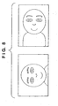
- the inclination of face in the image signal upon image sensing with the camera in a vertical position is different from that upon image sensing with the camera in a lateral position, as shown in Fig. 8 . Accordingly, the face area detection processing must be performed plural times in different directions.
- time for face detection must be reduced as much as possible. If much time is taken in face detection, processing time for control of focussing on the face and exposure is delayed, and release time lag from the user's image sensing instruction to actual image sensing with the camera is increased.
- An embodiment of the present invention provides a technique for detecting a human face at a high speed from an image obtained by image sensing.
- an image sensing apparatus as set out in claim 1 and a method of detecting images as set out in claim 6.
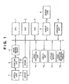
- Fig. 1 shows principal constituent elements of an image sensing apparatus according to the embodiment.
- the image sensing apparatus has a face detection function (a function of detecting an area corresponding to a human face from an image). Note that in the present embodiment, the image sensing apparatus is a digital camera.
- reference numeral 1 denotes a CPU which controls the overall apparatus; 2, a ROM in which a processing procedure (program) for the CPU 1 and various data are stored; 3, a RAM used as a work area for the CPU 1, in which an image obtained by image sensing is temporarily stored; 4, a memory card as a removable storage medium; 5, a memory slot to electrically connect the memory card 4 to the image sensing apparatus; and 6, an operation unit having operation buttons including a shutter button.
- the shutter button has three status, i.e., a release status, a half-depressed status, and a full-depressed status, and includes a sensor for detecting respective statuses.
- Numeral 7 denotes an optical lens group including zoom lens and focus lens; 8, a driver for control of focusing and zooming of the optical lens group 7; 9, an aperture unit; 10, a driver for the aperture unit 9; 11, an image sensing device such as a CCD or a CMOS having a photoelectric conversion function which converts an image formed via the optical lens group 7 and the aperture unit 9 into an electric signal; and 12, an image processing circuit which performs various image processings including Optical Black elimination processing (cancellation of any signal outputted from the image sensing device when the aperture is closed to prevent entrance of light from the subject), white balance processing, compression coding and decoding processing.
- Optical Black elimination processing cancellation of any signal outputted from the image sensing device when the aperture is closed to prevent entrance of light from the subject
- white balance processing compression coding and decoding processing.
- Numeral 13 denotes a display unit which displays an image obtained by image sensing and various menus; and 14, an attitude sensor which detects an attitude of the image sensing apparatus (first vertical position, second vertical position or lateral position) and outputs the result of detection.
- the attitude sensor 14 detects a status of the image sensing apparatus clockwise rotated more than 45° about an optical axis as a "first vertical position”, and a status of the apparatus counterclockwise rotated more than 45°, as a "second vertical position", and the other status, as a "lateral position".
- the image sensing apparatus in a position to obtain a rectangular image having long sides along a horizontal direction and a short sides along a vertical direction.
- Numeral 15 denotes a face detection processing circuit which detects an area corresponding to a human face from an image signal outputted from the image processing circuit 12.
- an image signal obtained with the image sensing device 11 is compression-encoded (generally, JPEG-encoded) by the image processing circuit 12, and stored in the memory card 4 connected to the memory slot 5.
- the image sensing apparatus of the present embodiment has image sensing modes including a portrait mode, a landscape mode and an auto mode.
- the portrait mode is programmed appropriately for image sensing of a person, to photograph a person as a central subject with low depth of field, such that the person cuts a good figure.
- the landscape mode is programmed appropriately for image sensing of a landscape, with infinite focal distance.
- the auto mode is programmed for automatically discriminating the feature of a subject thereby performing optimum image sensing.
- the image sensing apparatus of the present embodiment has a function of, when the portrait mode or the auto mode is selected, enabling the face detection function, based on high probability that a person is included in the subjects and image sensing is to be performed with the person as a central subject, on the other hand, when the landscape mode is selected, disabling the face detection function, based on low probability of image sensing with a person as a central subject. This function realizes high-speed image sensing processing in the landscape mode.
- Fig. 2 is a flowchart showing image sensing processing using the face detection function.
- the CPU 1 obtains a first image signal in a status the optical lens group 7 and the aperture unit 9 are controlled to set predetermined first exposure conditions (aperture value and exposure time) and focus position (step S102).
- the first image signal is used in determination of second exposure conditions and focus position based on information obtained from a particular area set as a default (step S103).
- the CPU 1 obtains a second image signal in a status where the optical lens group 7 and the aperture unit 9 are controlled to set the second exposure conditions and focus position (step S104).
- the subject image in the image signal is clarified and the precision of face detection processing is improved.
- the CPU 1 determines whether the current image sensing is lateral position image sensing, first vertical position image sensing or second vertical position, based on a detection signal from the attitude sensor 14 (step S105).
- the face detection processing circuit 15 determines, based on the result of determination, whether filter processing (edge detection processing) as preprocessing for face detection is to be performed in a vertical direction (step S106), a first horizontal direction (step S107) or a second horizontal direction (step S108) of the image, and performs one of the processings.
- step S105 If it is determined at step S105 that the image sensing is performed in the lateral position, the second image signal is read from the memory by 1 line in the vertical direction, then a band-pass filter is applied in the vertical direction, and a vertical high frequency signal (edge information) is stored in the RAM 3 (step S106). If it is determined that the image sensing is performed in the first vertical position, the second image signal is read from the memory by 1 line in the horizontal direction, then the band-pass filter is applied in the horizontal direction, and a horizontal high frequency signal is stored in the RAM 3 (step S107).
- the second image signal is read from the memory by 1 line in the horizontal direction, from the opposite side to that at step S107, then the band-pass filter is applied in the horizontal direction, and a horizontal high frequency signal is stored in the RAM 3 (step S108).
- the vertical and horizontal directions are defined on the assumption that a long side of the rectangular image obtained by the image sensing apparatus is along the horizontal direction and a short side is along the vertical direction.
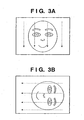
- the filter (edge detection processing) processing is performed at step S106 along arrows in Fig. 3A , and the result of processing is stored in the RAM 3.
- the filter processing (edge detection processing) is performed at step S107 along arrows in Fig. 3B , and the result of processing is stored in the RAM 3.
- the result of edge detection in Fig. 3A is greatly different from that in Fig. 3B . Accordingly, in the present embodiment, the direction of edge detection is changed in accordance with the result of detection by the attitude sensor 14.
- the face image in Fig. 3B may be previously rotated to the same direction as that of the face image in Fig. 3A before edge detection, or edge detection may be performed on the face image from plural directions.
- edge detection may be performed on the face image from plural directions.
- much processing time is required for rotation of the entire image signal on the assumption of the lateral position, the first vertical position and the second vertical position, or for edge detection from plural directions.
- the edge detection can be performed in the vertical direction to the person's face in the obtained image regardless of the attitude of the image sensing apparatus.
- accurate face detection processing can be performed in short time.
- the face detection processing circuit 15 performs pattern matching (step S109).
- the high frequency signal stored in the RAM 3 is compared with a previously-stored reference signal, i.e., shape pattern recognition processing regarding human eye is performed, thereby an eye candidate group is detected.
- the high frequency signal is compared with a reference signal group, thereby detection is made by shape recognition.
- the processing is performed in a frame of candidate group in the corresponding direction, thereby the pattern matching processing can be simplified.
- step S110 it is determined whether or not human eye (eyes) has been detected. If human eyes have been detected, the eye candidate group data is further reduced by linkage of eyes in pair among the detected eye candidate group. Then based on the eye candidate group data and other parts, (nose, mouth and ears), one of preset non-face condition filters (stored in the ROM 2) is selected, and an area passed through the filter is determined as a "face” (step S111).
- the face detection processing circuit 15 returns the sizes and positions of the areas determined as "eyes" and "face” to the CPU 1 (step S112).
- the CPU 1 performs weighting on a photometric area based on the detected face area, and sets the area including the eyes as a central portion, as a focus adjustment area (step S113).
- step S110 determines whether eyes have been detected. If it is determined at step S110 that eyes have not been detected, default photometric area and default focus adjustment area are set (step S116), and exposure control and focus adjustment control are performed based on these areas.
- step 114 when the photometric area and the focus adjustment area have been set, it is determined whether or not the shutter button has been full-depressed (step 114). The above processing is repeated as long as the shutter butter is half-depressed. Further, if the full depression of the shutter button has been detected (step S114), the aperture unit 9 is controlled to attain optimum luminance in the latest photometric area, the optical lens group 7 is driven to obtain focus on the latest focus adjustment area, and image sensing is performed. The obtained image signal is compression-encoded, and written into the memory card 4 (step S115).
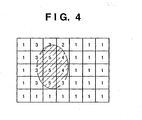
- a predetermined image screen is divided into plural blocks (small areas), and a luminance value in each block is calculated.
- an area enclosed within an ellipse is a face area detected by the face detection processing circuit 15.
- weighting is performed in accordance with the ratio of face area in each block. In this case, 5-level weighting is performed. "5" indicates that only the face area exists in the block. In a block including both face and non-face areas, a value corresponding to the ratio therebetween is assigned. In a block including only the non-face area, "1" is assigned.
- the aperture and shutter speed are calculated such that a mean luminance value of the integrated luminance value of the respective luminance values becomes a preset target luminance value.
- exposure correction to attain optimum luminance with preference to face area can be realized.
- exposure in backlight situation can be set to an optimum exposure level for a subject person.
- exposure correction may be performed by using only the luminance value obtained from the face area detected by the face detection processing circuit 15 without weighting.
- the focus adjustment area is set so as to include the detected eyes, and the optical lens group 7 is controlled to obtain focus within the focus adjustment area.
- the focus of the optical lens group 7 is moved by predetermined step width and image sensing is performed at every step then a luminance signal is generated from an image signal in a set focus adjustment area, and the band-pass filter is applied, thereby a high frequency signal group is generated. Then the sum of the absolute values of the respective high frequency signal group is calculated as an AF (Auto Focus) signal. A position with a maximum AF signal value is determined as a focused position, and the focus lens included in the optical lens group 7 is set to the position.
- AF Auto Focus
- the image screen is divided into plural small blocks covered with RGB color filters, and a white evaluation values (Cx, Cy) are calculated in each block by using the following expressions.
- the R, G and B values are obtained by photoelectric conversion of light flux passed through the R filter, G filter and G filter.
- the Y value is a luminance value obtained by calculation of these R, G and B values.
- the block is determined as white (referred to as "white search"), and a white balance gain is calculated from the integrated pixel value of the block.
- white search a white balance gain is calculated from the integrated pixel value of the block.
- This is a basic algorithm of generally used white balance processing.
- a white subject under a low color-temperature light source and a flesh-color subject under a high color-temperature light source have approximately the same color evaluation values, correct color temperature determination cannot be performed.
- a small block determined as face is excluded from the white search.
- flesh-color detection is performed similarly to white detection in an area determined as face, and the color temperature is specified from a preset flesh color and color temperature characteristic graph. Thus correct light-source color temperature can be calculated.
- the method of face detection can be changed in accordance with the attitude (lateral or vertical position) of the image sensing apparatus. Accordingly, a person's face can be detected at a high speed from an image obtained by image sensing.
- the image sensing apparatus is a digital camera, however, the present invention is not limited to this embodiment.
- the present invention can be implemented in other apparatuses (a digital video camera, a cellular phone with a camera and the like) than the digital camera.
- the face detection function is enabled if the image sensing mode is the portrait mode or the auto mode, however, the present invention is not limited to this arrangement.
- the image sensing apparatus of the embodiment may be further provided with a manual setting mode to disable the face detection function in accordance with the user's instruction even if the image sensing mode is the portrait mode or the auto mode.
- an area corresponding to a face is detected by detecting the positions of eyes and other parts based on the eye positions, however, the present invention is not limited to this arrangement.
- the present invention can be applied to only detection of eyes or only detection of other parts by changing the method of detection in accordance with the attitude of the image sensing apparatus.
- the method of face detection can be changed in accordance with the attitude of the image sensing apparatus. Accordingly, a person's face can be detected at a high speed from an image obtained by image sensing.
Claims (10)
- Bildaufnahmevorrichtung, die einen Bildsensor (11) und eine Gesichtserfassungsschaltung (15) zum Erfassen eines Gesichts durch Erfassen eines Randes in einem durch den Bildsensor aufgenommenen Bild aufweist,
gekennzeichnet durch
eine Orientierungserfassungseinheit (14) zum Erfassen der Orientierung der Vorrichtung, und
wobei die Gesichtserfassungsschaltung dazu angepasst ist, eine Abtastrichtung zum Erfassen eines Randes in einem durch den Bildsensor aufgenommenen Bild gemäß dem Ergebnis der Orientierungserfassungseinheit zu bestimmen. - Vorrichtung gemäß Anspruch 1, dadurch gekennzeichnet, dass die Gesichtserfassungsschaltung dazu angepasst ist, ein Gesicht durch Abgleichen des Ergebnisses einer Randerfassung mit einem vorbestimmten Bezugsdatensatz zu erfassen.
- Vorrichtung gemäß Anspruch 1 oder 2, weiterhin gekennzeichnet durch eine Steuerungsschaltung zum Durchführen einer Fokuseinstellung, um einen Fokus auf das durch die Gesichtserfassungsschaltung erfasste Gesicht zu erhalten.
- Vorrichtung gemäß einem vorangehenden Anspruch, weiterhin gekennzeichnet durch eine Steuerungsschaltung, die dazu angepasst ist, eine Belichtungssteuerung gemäß Leuchtdichteinformationen durchzuführen, die mit Bezug auf ein durch die Gesichtserfassungsschaltung erfasstes Gesicht gewichtet sind.
- Vorrichtung gemäß einem vorangehenden Anspruch, weiterhin gekennzeichnet durch:eine Bildaufnahmebetriebsart-Einstellungseinheit zum Auswählen eines Bildaufnahmeprogramms aus einer Vielzahl von Programmen,wobei die Merkmalsextraktionsschaltung die Gesichtserfassung von einem durch den Bildsensor aufgenommenen Bild nicht durchführt, falls ein vorbestimmtes Bildaufnahmeprogramm durch die Bildaufnahmebetriebsart-Einstellungseinheit eingestellt wurde.
- Verfahren eines Steuerns einer Bildaufnahmevorrichtung, die einen Bildsensor (11) und eine Gesichtserfassungsschaltung (15) aufweist, um ein Gesicht durch Erfassen eines Randes in einem durch den Bildsensor aufgenommenen Bild zu erfassen, gekennzeichnet durch die Schritte:Erfassen der Orientierung der Vorrichtung, undBestimmen einer Abtastrichtung zum Erfassen eines Randes in einem durch den Bildsensor aufgenommenen Bild gemäß einer Ausgabe der Orientierungserfassungseinheit.
- Verfahren gemäß Anspruch 6, weiterhin mit einem Erfassen eines Gesichts durch Abgleichen des Ergebnisses einer Randerfassung mit vorbestimmten Bezugsdaten.
- Verfahren gemäß Anspruch 6 oder 7, weiterhin mit einer Steuerungsschaltung zum Durchführen einer Fokuseinstellung, um einen Fokus auf das durch die Gesichtserfassungsschaltung erfasste Gesicht zu erhalten.
- Verfahren gemäß einem der Ansprüche 6 bis 8, weiterhin mit einem Durchführen einer Belichtungssteuerung gemäß Leuchtdichteinformationen, die mit Bezug auf ein durch die Gesichtserfassungsschaltung erfasstes Gesicht gewichtet sind.
- Verfahren gemäß einem der Ansprüche 6 bis 9, mit:Auswählen eines Bildaufnahmeprogramms für die Vorrichtung unter einer Vielzahl von Programmen, undwobei der Merkmalsextraktionsschritt mit Bezug auf ein durch den Bildsensor aufgenommenes Bild nicht durchgeführt wird, falls ein vorbestimmtes Bildaufnahmeprogramm durch die Bildaufnahmebetriebsart-Einstellungseinheit eingestellt wurde.
Applications Claiming Priority (4)
| Application Number | Priority Date | Filing Date | Title |
|---|---|---|---|
| JP2003338812 | 2003-09-29 | ||
| JP2003338812 | 2003-09-29 | ||
| JP2004267514 | 2004-09-14 | ||
| JP2004267514A JP4290100B2 (ja) | 2003-09-29 | 2004-09-14 | 撮像装置及びその制御方法 |
Publications (3)
| Publication Number | Publication Date |
|---|---|
| EP1519560A2 EP1519560A2 (de) | 2005-03-30 |
| EP1519560A3 EP1519560A3 (de) | 2006-05-03 |
| EP1519560B1 true EP1519560B1 (de) | 2008-11-12 |
Family
ID=34197278
Family Applications (1)
| Application Number | Title | Priority Date | Filing Date |
|---|---|---|---|
| EP04255918A Expired - Fee Related EP1519560B1 (de) | 2003-09-29 | 2004-09-28 | Bildaufnahmevorrichtung und Steuerungsverfahren dafür |
Country Status (6)
| Country | Link |
|---|---|
| US (1) | US7564486B2 (de) |
| EP (1) | EP1519560B1 (de) |
| JP (1) | JP4290100B2 (de) |
| KR (1) | KR100659387B1 (de) |
| CN (1) | CN1604621B (de) |
| DE (1) | DE602004017684D1 (de) |
Families Citing this family (47)
| Publication number | Priority date | Publication date | Assignee | Title |
|---|---|---|---|---|
| US20030206654A1 (en) * | 2002-05-01 | 2003-11-06 | Heng-Tun Teng | Replacing method of an object in a dynamic image |
| US8326084B1 (en) * | 2003-11-05 | 2012-12-04 | Cognex Technology And Investment Corporation | System and method of auto-exposure control for image acquisition hardware using three dimensional information |
| KR100608596B1 (ko) * | 2004-12-28 | 2006-08-03 | 삼성전자주식회사 | 얼굴 검출을 기반으로 하는 휴대용 영상 촬영 기기 및영상 촬영 방법 |
| JP4284448B2 (ja) * | 2005-01-28 | 2009-06-24 | 富士フイルム株式会社 | 画像処理装置及び方法 |
| JP4457980B2 (ja) * | 2005-06-21 | 2010-04-28 | ソニー株式会社 | 撮像装置、この装置の処理方法およびその方法をコンピュータに実行させるプログラム |
| DE602006009191D1 (de) * | 2005-07-26 | 2009-10-29 | Canon Kk | Bildaufnahmegerät und -verfahren |
| US20070031060A1 (en) * | 2005-08-04 | 2007-02-08 | Canon Kabushiki Kaisha | Image processing apparatus, method for calculating white balance evaluation value, program including program code for realizing the method for calculating white balance evaluation value, and storage medium for storing the program |
| JP4619927B2 (ja) * | 2005-11-01 | 2011-01-26 | 富士フイルム株式会社 | 顔検出方法および装置並びにプログラム |
| JP4521360B2 (ja) * | 2006-01-18 | 2010-08-11 | 富士フイルム株式会社 | 対象物検出装置および画像ファイル記録装置ならびにそれらの制御方法 |
| JP4579169B2 (ja) * | 2006-02-27 | 2010-11-10 | 富士フイルム株式会社 | 撮影条件設定方法およびこれを用いた撮影装置 |
| JP5319078B2 (ja) * | 2006-07-07 | 2013-10-16 | オリンパスイメージング株式会社 | カメラ、カメラの画像処理方法、プログラム、記録媒体 |
| JP4904108B2 (ja) | 2006-07-25 | 2012-03-28 | 富士フイルム株式会社 | 撮影装置及び画像表示制御方法 |
| JP4943769B2 (ja) * | 2006-08-15 | 2012-05-30 | 富士フイルム株式会社 | 撮影装置および合焦位置探索方法 |
| US8049807B2 (en) * | 2006-09-05 | 2011-11-01 | Olympus Imaging Corp. | Digital camera and dust reduction apparatus for digital camera |
| US20080107341A1 (en) * | 2006-11-02 | 2008-05-08 | Juwei Lu | Method And Apparatus For Detecting Faces In Digital Images |
| JP4286292B2 (ja) * | 2007-01-30 | 2009-06-24 | 三洋電機株式会社 | 電子カメラ |
| JP4989243B2 (ja) | 2007-02-05 | 2012-08-01 | 株式会社リコー | 撮像装置及びその被写体検出方法 |
| JP4315212B2 (ja) | 2007-05-02 | 2009-08-19 | カシオ計算機株式会社 | 撮像装置、撮像制御プログラム及び撮像制御方法 |
| KR101363017B1 (ko) * | 2007-08-23 | 2014-02-12 | 삼성전자주식회사 | 얼굴영상 촬영 및 분류 시스템과 방법 |
| JP5004726B2 (ja) * | 2007-09-05 | 2012-08-22 | キヤノン株式会社 | 撮像装置、レンズユニットおよび制御方法 |
| US20090202180A1 (en) * | 2008-02-11 | 2009-08-13 | Sony Ericsson Mobile Communications Ab | Rotation independent face detection |
| JP2009194469A (ja) * | 2008-02-12 | 2009-08-27 | Ricoh Co Ltd | 撮像装置 |
| JP5141317B2 (ja) * | 2008-03-14 | 2013-02-13 | オムロン株式会社 | 対象画像検出デバイス、制御プログラム、および該プログラムを記録した記録媒体、ならびに対象画像検出デバイスを備えた電子機器 |
| JP4911165B2 (ja) | 2008-12-12 | 2012-04-04 | カシオ計算機株式会社 | 撮像装置、顔検出方法及びプログラム |
| JP5144487B2 (ja) * | 2008-12-15 | 2013-02-13 | キヤノン株式会社 | 主顔選択装置、その制御方法、撮像装置及びプログラム |
| JP5264516B2 (ja) * | 2009-01-07 | 2013-08-14 | キヤノン株式会社 | 撮像装置、その制御方法、及びプログラム |
| JP5332668B2 (ja) * | 2009-02-04 | 2013-11-06 | 株式会社ニコン | 撮像装置および被写体検出プログラム |
| JP5035702B2 (ja) | 2009-02-27 | 2012-09-26 | カシオ計算機株式会社 | 撮像装置、オートフォーカス方法及びプログラム |
| KR20100099008A (ko) * | 2009-03-02 | 2010-09-10 | 삼성전자주식회사 | 오토 포커싱 제어 방법 및 장치, 이를 이용한 디지털 촬영 장치 |
| JP2010226558A (ja) * | 2009-03-25 | 2010-10-07 | Sony Corp | 画像処理装置、画像処理方法、及び、プログラム |
| US8228403B2 (en) * | 2009-12-31 | 2012-07-24 | Omnivision Technologies, Inc. | Generating column offset corrections for image sensors |
| US8405736B2 (en) * | 2010-04-07 | 2013-03-26 | Apple Inc. | Face detection using orientation sensor data |
| JP2012034069A (ja) * | 2010-07-29 | 2012-02-16 | Nikon Corp | 画像処理装置、および画像処理プログラム |
| US8593558B2 (en) * | 2010-09-08 | 2013-11-26 | Apple Inc. | Camera-based orientation fix from portrait to landscape |
| JP5725793B2 (ja) * | 2010-10-26 | 2015-05-27 | キヤノン株式会社 | 撮像装置およびその制御方法 |
| US8873840B2 (en) * | 2010-12-03 | 2014-10-28 | Microsoft Corporation | Reducing false detection rate using local pattern based post-filter |
| US8971574B2 (en) * | 2011-11-22 | 2015-03-03 | Ulsee Inc. | Orientation correction method for electronic device used to perform facial recognition and electronic device thereof |
| CN102982536B (zh) * | 2012-11-05 | 2015-07-22 | 华为技术有限公司 | 处理图像的方法和设备 |
| JP5697650B2 (ja) * | 2012-12-13 | 2015-04-08 | キヤノン株式会社 | 撮像装置とその制御方法 |
| CN103516985A (zh) * | 2013-09-18 | 2014-01-15 | 上海鼎为软件技术有限公司 | 移动终端及其获取图像的方法 |
| JP5874753B2 (ja) * | 2014-01-28 | 2016-03-02 | カシオ計算機株式会社 | 撮像装置、撮像方法及びプログラム |
| JP6411829B2 (ja) * | 2014-09-17 | 2018-10-24 | オリンパス株式会社 | 撮像装置及び像ブレ補正方法 |
| KR101715325B1 (ko) * | 2014-12-09 | 2017-03-13 | (유)도건테크 | 3차원 스캔 기술을 사용한 사진 설계 도면 제공 방법 및 시스템 |
| US9754355B2 (en) | 2015-01-09 | 2017-09-05 | Snap Inc. | Object recognition based photo filters |
| US20170272716A1 (en) * | 2016-03-15 | 2017-09-21 | Casio Computer Co., Ltd. | Projection apparatus, projection control method, and storage medium |
| JP2019168999A (ja) | 2018-03-23 | 2019-10-03 | カシオ計算機株式会社 | 撮像装置、撮像方法及びプログラム |
| CN116546333B (zh) * | 2023-04-03 | 2023-10-31 | 华光影像科技合肥有限公司 | 同时输出不同拍摄模式的视频画面的方法、系统和摄像机 |
Family Cites Families (18)
| Publication number | Priority date | Publication date | Assignee | Title |
|---|---|---|---|---|
| JPS57131185A (en) * | 1981-02-06 | 1982-08-13 | Hitachi Ltd | Color image pickup device |
| KR940017750A (ko) * | 1992-12-29 | 1994-07-27 | 이헌조 | 비디오 카메라의 화상 기울림 보정장치 |
| JPH07143434A (ja) | 1993-06-23 | 1995-06-02 | Nikon Corp | 撮影画像方向を一定にするデジタル電子スチルカメラ |
| JP3557659B2 (ja) | 1994-08-22 | 2004-08-25 | コニカミノルタホールディングス株式会社 | 顔抽出方法 |
| US5629752A (en) * | 1994-10-28 | 1997-05-13 | Fuji Photo Film Co., Ltd. | Method of determining an exposure amount using optical recognition of facial features |
| US6727948B1 (en) * | 1997-07-15 | 2004-04-27 | Silverbrook Research Pty Ltd | Utilizing autofocus information for image processing in a digital camera |
| US6597817B1 (en) * | 1997-07-15 | 2003-07-22 | Silverbrook Research Pty Ltd | Orientation detection for digital cameras |
| KR100263168B1 (ko) | 1997-12-30 | 2000-08-01 | 윤종용 | 디지털 스틸 카메라의 다중 저장장치 |
| JP2001091819A (ja) * | 1999-09-17 | 2001-04-06 | Olympus Optical Co Ltd | カメラの測距装置 |
| JP3980234B2 (ja) | 2000-01-07 | 2007-09-26 | ペンタックス株式会社 | デジタルカメラ |
| JP2001215403A (ja) | 2000-02-01 | 2001-08-10 | Canon Inc | 撮像装置および焦点の自動検出方法 |
| KR100406609B1 (ko) * | 2001-04-18 | 2003-11-20 | 삼성테크윈 주식회사 | 촬영 장치의 촬영 모드 자동 변환 장치 및 그 제어 방법 |
| US7298412B2 (en) * | 2001-09-18 | 2007-11-20 | Ricoh Company, Limited | Image pickup device, automatic focusing method, automatic exposure method, electronic flash control method and computer program |
| JP2004145291A (ja) * | 2002-10-03 | 2004-05-20 | Casio Comput Co Ltd | 画像表示装置、画像表示方法及びプログラム |
| JP2004234688A (ja) | 2004-04-05 | 2004-08-19 | Konica Minolta Holdings Inc | 顔抽出方法 |
| JP2004234689A (ja) | 2004-04-05 | 2004-08-19 | Konica Minolta Holdings Inc | 顔抽出方法 |
| JP2004265431A (ja) | 2004-04-05 | 2004-09-24 | Konica Minolta Holdings Inc | 顔抽出方法 |
| JP2004206738A (ja) | 2004-04-05 | 2004-07-22 | Konica Minolta Holdings Inc | 顔抽出方法 |
-
2004
- 2004-09-14 JP JP2004267514A patent/JP4290100B2/ja not_active Expired - Fee Related
- 2004-09-24 KR KR1020040077097A patent/KR100659387B1/ko not_active IP Right Cessation
- 2004-09-28 EP EP04255918A patent/EP1519560B1/de not_active Expired - Fee Related
- 2004-09-28 US US10/951,483 patent/US7564486B2/en not_active Expired - Fee Related
- 2004-09-28 DE DE602004017684T patent/DE602004017684D1/de active Active
- 2004-09-29 CN CN2004100831641A patent/CN1604621B/zh not_active Expired - Fee Related
Also Published As
| Publication number | Publication date |
|---|---|
| US20050088536A1 (en) | 2005-04-28 |
| KR20050031427A (ko) | 2005-04-06 |
| KR100659387B1 (ko) | 2006-12-19 |
| US7564486B2 (en) | 2009-07-21 |
| JP4290100B2 (ja) | 2009-07-01 |
| EP1519560A2 (de) | 2005-03-30 |
| CN1604621B (zh) | 2010-08-18 |
| DE602004017684D1 (de) | 2008-12-24 |
| EP1519560A3 (de) | 2006-05-03 |
| JP2005130468A (ja) | 2005-05-19 |
| CN1604621A (zh) | 2005-04-06 |
Similar Documents
| Publication | Publication Date | Title |
|---|---|---|
| EP1519560B1 (de) | Bildaufnahmevorrichtung und Steuerungsverfahren dafür | |
| EP3499863B1 (de) | Verfahren und vorrichtung zur bildverarbeitung | |
| EP1522952B1 (de) | Digitalkamera | |
| JP4671133B2 (ja) | 画像処理装置 | |
| JP4674471B2 (ja) | デジタルカメラ | |
| US8797423B2 (en) | System for and method of controlling a parameter used for detecting an objective body in an image and computer program | |
| JP3888996B2 (ja) | 小型デジタルカメラのズーム(zoom)方法 | |
| US20080136958A1 (en) | Camera having a focus adjusting system and a face recognition function | |
| EP1855464A2 (de) | Verfahren zur Anzeige eines Gesichtserkennungsrahmens, Verfahren zur Anzeige von Zeicheninformationen und Bildaufnahmevorrichtung | |
| US8411159B2 (en) | Method of detecting specific object region and digital camera | |
| US7957633B2 (en) | Focus adjusting apparatus and focus adjusting method | |
| US8494354B2 (en) | Focus adjusting apparatus and focus adjusting method | |
| US20090016708A1 (en) | Image detection device, focusing device, image-capturing device, image detection method, and focusing method | |
| JP2006208558A (ja) | 撮像装置 | |
| JP2006211139A (ja) | 撮像装置 | |
| JP2003167182A (ja) | オートフォーカス装置 | |
| US7391461B2 (en) | Apparatus, method and control computer program for imaging a plurality of objects at different distances | |
| JP5899629B2 (ja) | 撮像装置 | |
| JP2003156680A (ja) | 被写体抽出装置及び撮影装置 | |
| JP5087936B2 (ja) | カメラ | |
| JP7154758B2 (ja) | 画像処理装置及びその制御方法 | |
| JP2007049442A (ja) | 撮像装置 | |
| US7046289B2 (en) | Automatic focusing device, camera, and automatic focusing method | |
| JP3628648B2 (ja) | 光学系制御装置 | |
| JP2008145782A (ja) | 焦点調節装置を備えたカメラ |
Legal Events
| Date | Code | Title | Description |
|---|---|---|---|
| PUAI | Public reference made under article 153(3) epc to a published international application that has entered the european phase |
Free format text: ORIGINAL CODE: 0009012 |
|
| AK | Designated contracting states |
Kind code of ref document: A2 Designated state(s): AT BE BG CH CY CZ DE DK EE ES FI FR GB GR HU IE IT LI LU MC NL PL PT RO SE SI SK TR |
|
| AX | Request for extension of the european patent |
Extension state: AL HR LT LV MK |
|
| PUAL | Search report despatched |
Free format text: ORIGINAL CODE: 0009013 |
|
| AK | Designated contracting states |
Kind code of ref document: A3 Designated state(s): AT BE BG CH CY CZ DE DK EE ES FI FR GB GR HU IE IT LI LU MC NL PL PT RO SE SI SK TR |
|
| AX | Request for extension of the european patent |
Extension state: AL HR LT LV MK |
|
| 17P | Request for examination filed |
Effective date: 20061103 |
|
| AKX | Designation fees paid |
Designated state(s): DE FR GB IT NL |
|
| 17Q | First examination report despatched |
Effective date: 20070730 |
|
| GRAP | Despatch of communication of intention to grant a patent |
Free format text: ORIGINAL CODE: EPIDOSNIGR1 |
|
| RIC1 | Information provided on ipc code assigned before grant |
Ipc: G06K 9/00 20060101AFI20080313BHEP |
|
| GRAS | Grant fee paid |
Free format text: ORIGINAL CODE: EPIDOSNIGR3 |
|
| GRAA | (expected) grant |
Free format text: ORIGINAL CODE: 0009210 |
|
| AK | Designated contracting states |
Kind code of ref document: B1 Designated state(s): DE FR GB IT NL |
|
| REG | Reference to a national code |
Ref country code: GB Ref legal event code: FG4D |
|
| REF | Corresponds to: |
Ref document number: 602004017684 Country of ref document: DE Date of ref document: 20081224 Kind code of ref document: P |
|
| NLV1 | Nl: lapsed or annulled due to failure to fulfill the requirements of art. 29p and 29m of the patents act | ||
| PG25 | Lapsed in a contracting state [announced via postgrant information from national office to epo] |
Ref country code: NL Free format text: LAPSE BECAUSE OF FAILURE TO SUBMIT A TRANSLATION OF THE DESCRIPTION OR TO PAY THE FEE WITHIN THE PRESCRIBED TIME-LIMIT Effective date: 20081112 |
|
| PLBE | No opposition filed within time limit |
Free format text: ORIGINAL CODE: 0009261 |
|
| STAA | Information on the status of an ep patent application or granted ep patent |
Free format text: STATUS: NO OPPOSITION FILED WITHIN TIME LIMIT |
|
| 26N | No opposition filed |
Effective date: 20090813 |
|
| PG25 | Lapsed in a contracting state [announced via postgrant information from national office to epo] |
Ref country code: IT Free format text: LAPSE BECAUSE OF FAILURE TO SUBMIT A TRANSLATION OF THE DESCRIPTION OR TO PAY THE FEE WITHIN THE PRESCRIBED TIME-LIMIT Effective date: 20081112 |
|
| REG | Reference to a national code |
Ref country code: FR Ref legal event code: PLFP Year of fee payment: 12 |
|
| PGFP | Annual fee paid to national office [announced via postgrant information from national office to epo] |
Ref country code: DE Payment date: 20150930 Year of fee payment: 12 Ref country code: GB Payment date: 20150922 Year of fee payment: 12 |
|
| PGFP | Annual fee paid to national office [announced via postgrant information from national office to epo] |
Ref country code: FR Payment date: 20150928 Year of fee payment: 12 |
|
| REG | Reference to a national code |
Ref country code: DE Ref legal event code: R119 Ref document number: 602004017684 Country of ref document: DE |
|
| GBPC | Gb: european patent ceased through non-payment of renewal fee |
Effective date: 20160928 |
|
| REG | Reference to a national code |
Ref country code: FR Ref legal event code: ST Effective date: 20170531 |
|
| PG25 | Lapsed in a contracting state [announced via postgrant information from national office to epo] |
Ref country code: FR Free format text: LAPSE BECAUSE OF NON-PAYMENT OF DUE FEES Effective date: 20160930 Ref country code: DE Free format text: LAPSE BECAUSE OF NON-PAYMENT OF DUE FEES Effective date: 20170401 Ref country code: GB Free format text: LAPSE BECAUSE OF NON-PAYMENT OF DUE FEES Effective date: 20160928 |