EP1519500A1 - System and method for optically labeled packet transmission - Google Patents
System and method for optically labeled packet transmission Download PDFInfo
- Publication number
- EP1519500A1 EP1519500A1 EP04255623A EP04255623A EP1519500A1 EP 1519500 A1 EP1519500 A1 EP 1519500A1 EP 04255623 A EP04255623 A EP 04255623A EP 04255623 A EP04255623 A EP 04255623A EP 1519500 A1 EP1519500 A1 EP 1519500A1
- Authority
- EP
- European Patent Office
- Prior art keywords
- label
- payload
- dpsk
- optically labeled
- signal
- Prior art date
- Legal status (The legal status is an assumption and is not a legal conclusion. Google has not performed a legal analysis and makes no representation as to the accuracy of the status listed.)
- Withdrawn
Links
- 238000000034 method Methods 0.000 title claims abstract description 14
- 230000005540 biological transmission Effects 0.000 title claims description 9
- 230000003287 optical effect Effects 0.000 claims description 16
- 238000003780 insertion Methods 0.000 claims description 9
- 230000037431 insertion Effects 0.000 claims description 9
- 238000006243 chemical reaction Methods 0.000 claims description 5
- 230000008569 process Effects 0.000 claims description 4
- 230000008033 biological extinction Effects 0.000 claims description 3
- 238000004891 communication Methods 0.000 claims description 3
- 238000001514 detection method Methods 0.000 abstract description 11
- 238000010586 diagram Methods 0.000 description 11
- 230000035945 sensitivity Effects 0.000 description 8
- 238000005516 engineering process Methods 0.000 description 5
- 230000010287 polarization Effects 0.000 description 4
- 230000008859 change Effects 0.000 description 3
- 239000000835 fiber Substances 0.000 description 3
- 238000009738 saturating Methods 0.000 description 3
- 101150071746 Pbsn gene Proteins 0.000 description 2
- 229910003327 LiNbO3 Inorganic materials 0.000 description 1
- 238000001069 Raman spectroscopy Methods 0.000 description 1
- 238000010521 absorption reaction Methods 0.000 description 1
- 230000007423 decrease Effects 0.000 description 1
- 230000001934 delay Effects 0.000 description 1
- 239000006185 dispersion Substances 0.000 description 1
- 239000006528 fwm medium Substances 0.000 description 1
- 230000006855 networking Effects 0.000 description 1
- 230000009022 nonlinear effect Effects 0.000 description 1
- 239000000382 optic material Substances 0.000 description 1
- 238000011084 recovery Methods 0.000 description 1
- 239000004065 semiconductor Substances 0.000 description 1
- 230000007704 transition Effects 0.000 description 1
Images



Classifications
-
- H—ELECTRICITY
- H04—ELECTRIC COMMUNICATION TECHNIQUE
- H04B—TRANSMISSION
- H04B10/00—Transmission systems employing electromagnetic waves other than radio-waves, e.g. infrared, visible or ultraviolet light, or employing corpuscular radiation, e.g. quantum communication
- H04B10/50—Transmitters
- H04B10/501—Structural aspects
- H04B10/503—Laser transmitters
- H04B10/505—Laser transmitters using external modulation
-
- H—ELECTRICITY
- H04—ELECTRIC COMMUNICATION TECHNIQUE
- H04B—TRANSMISSION
- H04B10/00—Transmission systems employing electromagnetic waves other than radio-waves, e.g. infrared, visible or ultraviolet light, or employing corpuscular radiation, e.g. quantum communication
- H04B10/50—Transmitters
- H04B10/501—Structural aspects
- H04B10/503—Laser transmitters
- H04B10/505—Laser transmitters using external modulation
- H04B10/5051—Laser transmitters using external modulation using a series, i.e. cascade, combination of modulators
Definitions
- the present invention relates generally to optically labeled packet transmission, and more specifically to a system and method for transmitting optically labeled packets to allow for optical-label packet switching.
- Optical packet switching is an attractive technology that enables more effective and flexible utilization of the capacity of WDM optical networks by providing sub-wavelength granularity.
- Optical-label switching as one of the promising packet switching schemes, offers several key features that are important to future data-intensive networks. These features include protocol and format independent transparency at the all-optical data plane, simplification in the control plane, and interoperability with legacy and emerging networking technologies including GMPLS. Such a switching scheme is discussed in D. J. Blumenthal, et al., “All-Optical Label Swapping Networks and Technologies", Journal of Lightwave Technologies, Vol. 18, No. 12, pp. 2058-2075 (2000), which is incorporated herein by reference.
- Optical-label packet transmission schemes have been proposed in which a packet payload is carried using amplitude-shift-keying (ASK) modulation and the packet label is carried using differential-phase-shift-keying (DPSK) modulation.
- ASK amplitude-shift-keying
- DPSK differential-phase-shift-keying
- the present invention provides a system and method for transmitting optically labeled packets using DPSK/ASK modulation.
- a system comprising a transmitter including at least two modulators adapted to provide DPSK modulation of a payload portion of optically labeled packets and ASK modulation for a label portion of the optically labeled packets.
- the system may further include a receiver containing a balanced detector for detection of the payload portion of the optically labeled packets.
- a communication method for transmission of optically labeled packets comprising the step of modulating light from a laser source using DPSK modulation to carry payload information and ASK modulation to carry label information.
- a system and method which use a DPSK/ASK modulation format to carry payload/label information, and which use balanced detection for the DPSK payload portion of a DPSK/ASK signal.
- the present invention offers a number of advantages over prior art schemes. First, DPSK is used to carry a high-speed payload, so the temperature stability of a delay-line interferometer (used in DPSK demodulation) is significantly improved, and its polarization sensitivity is significantly reduced, due to the reduced relative delay between the two arms of the interferometer. Second, the data rate of the label can be adjusted (e.g., from 2.5-Gb/s to 155-Mb/s) without changing the interferometer.
- the use of a balanced receiver can not only improve the tolerance of a DPSK receiver to packet power fluctuations, but can also substantially increase the DPSK receiver sensitivity (e.g., by about 3 dB) as well as the ASK receiver sensitivity (by allowing a higher extinction ratio for ASK modulation).
- the removal and insertion of a label is substantially easier since it is intensity modulated (as opposed to phase modulated).
- the system 100 preferably includes a DPSK/ASK transmitter 110, and a DPSK/ASK receiver 150.
- the light from a laser 112 is DPSK modulated using payload data signal 113 to drive a phase modulator 114.
- the payload data signal 113 is a high speed signal having a data rate of greater than about 2.5 Gb/s.
- the phase modulator 114 may be a single-waveguide phase modulator, a Mach Zehnder (MZM), or the like.
- MZM can be made from a variety of electro-optic materials, for example, LiNbO 3 , and is preferably biased at its null point and driven at ⁇ 2V ⁇ to switch the phase of the light signal between 0 and ⁇ .
- a chirp-free MZM is preferably employed to produce a DPSK signal with substantially perfect phase values (0 and ⁇ ).
- an encoder 115 is used to perform DPSK encoding prior to phase modulation.
- An intensity modulator 120 is coupled to the phase modulator 114 to provide ASK modulation of the light from the laser 112.
- the intensity modulator 120 is preferably driven by an ASK label data signal 125.
- the ASK label data signal is preferably a low speed signal having a data rate of less than about 1/4 of the payload data rate.
- the intensity modulator 120 is driven to produce a low extinction ratio (ER) of between about 2 dB and about 8 dB.
- the intensity modulator 120 can be a MZM, an electro-absorption modulator (EAM), or the like.
- a MZM a low ER can be achieved by under-driving the MZM and shifting the bias point away from the quadrature point.
- a low ER can be achieved by shifting the bias point.
- the receiver 150 preferably includes an erbium-doped fiber amplifier 160 (EDFA) as an optical pre-amplifier.
- An optical filter 161 is preferably provided after the amplifier 160 to reduce the penalty from amplified-spontaneous-emission (ASE) noise.
- the amplified signal is then preferably separated into two paths 165, 166.
- One path 165 transmits the received signal to a DPSK receiver 190.
- the DPSK receiver 190 preferably comprises a one-bit delay interferometer 192, a balanced detector 194, and a differential RF amplifier 196 for detection of the DPSK payload (i.e., the DPSK modulated portion or component of the optically labeled packet).
- the other path 166 transmits the received signal to an ASK detector 198 for detection of the packet label (i.e., the ASK modulated portion or component of the optically labeled packet).
- the optical delay interferometer 192 of the DPSK receiver 190 divides the light on path 165 into two arms and delays one arm by about one-bit period. It can be understood by those skilled in the art that the delay provided by the delay interferometer 192 can vary from precisely one-bit period while still providing sufficient delay to allow reception of the payload portion of received packets. Preferably, the delay provided by the delay interferometer 192 is between about 0.8 and about 1.2 times the bit period.
- a label processing device (not shown) is provided to provide label reading, label insertion, and/or label removal.
- FIG. 6 illustrates label removal and insertion according to preferred embodiments of the invention.
- a chirp-free saturating amplifier 610 with a speed similar to (or faster than) the label data rate is preferably used.
- Such an amplifier may be a relatively simple and compact semiconductor optical amplifier (SOA), a fiber Raman amplifier, or the like.
- Fig. 7 shows a DPSK eye diagram with the ASK label removed using a saturating SOA.
- a low-speed intensity modulator 620 e.g., a MZM or an EAM
- the intensity modulator is preferably polarization-independent since the polarization of the signal is varying with time and location.
- the label removal and insertion in accordance with the present invention are substantially simplified.
- phase-maintaining 4-wave-mixing (FWM) processes may be employed in accordance with the present invention.
- the FWM processes can be realized, for example, in a highly-nonlinear fiber or a fast SOA.
- FIG. 8 illustrates wavelength conversion of DPSK/ASK packets in accordance with a preferred embodiment of the invention. Both the amplitude and phase of the optical packets are preferably preserved.
- optically-labeled DPSK/ASK packets at wavelngth ⁇ 1 are passed through the FWM medium together with pump light at wavelength ⁇ 0.
- New packets at wavelength ⁇ 2 with ⁇ 2 ⁇ 2 ⁇ 0- ⁇ 1 are generated (through the FWM process), and carry the same payload and label information as the original packets.
- FIG. 2 is a plot illustrating the constellation diagram of the payload and label symbols in a phasor diagram.
- the x-axis represents the real part of the optical field
- the y-axis represents the imaginary part of the optical field.
- the DPSK payload data 113 may be recovered at the receiver 150 by setting the decision threshold at the y-axis to compare the signs (or the phases) of adjacent bits. Such recovery of the DPSK payload data can be realized by using a delay interferometer 192 and a balanced detector 194, as discussed above and setting the decision threshold at 0. For example, if two adjacent bits have the same (or opposite) sign, then ''1'' (or "-1") is determined.
- the ASK label data can be retrieved by setting the decision threshold at the circle 210 with a radius that is the mean of the larger and smaller amplitude of the symbols.
- An embodiment of the invention has been demonstrated experimentally with a 10-Gb/s payload signal and 2.5-Gb/s label signal.
- the laser used was a tunable laser operating at 1550 nm.
- the payload data at 10-Gb/s was added onto the laser light by modulating a MZM which was biased at null and driven at 2V ⁇ to achieve phase modulation.
- An intensity modulator was used to insert label information at 2.5-Gb/s on the DPSK signal from the MZM by ASK modulation with 6-dB ER.
- the ER of the intensity modulation was set to allow approximately equal receiver sensitivity for the payload and label with the label data rate of 1 ⁇ 4 of the payload data rate.
- the low ER was achieved by under-driving MZM at about 0.8V ⁇ and shifting the bias point away from the quadrature point by about 0.1 V ⁇ .
- an integrated 2-stage X-cut (chirp-free) modulator with 10-GHz bandwidth and 5.5-dB total insertion loss was used.
- an EDFA with approximately 4.5 dB NF was used as an optical pre-amplifier.
- the optical filter after the pre-amplifier had a 3-dB bandwidth of about 100-GHz.
- the amplified signal was separated into two paths, one entering a DPSK receiver comprising a 100-ps delay interferometer, a balanced detector, and a differential RF amplifier for payload detection, and the other entering an ASK detector for label detection.
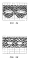
- FIGS. 3a-b show eye diagrams detected at the DPSK receiver and ASK receiver (with a 1.5-GHz Bessel filter) with a continuous DPSK/ASK data stream.
- an optimum decision level was about 0.
- the "0" level is about 1 ⁇ 4 of''1'' level since the ER of the ASK modulator is about 6 dB.
- the 1.5-GHz Bessel filter was used to reduce the intensity fluctuations at the phase transitions in DPSK data and to limit electrical noise.
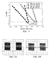
- FIGS. 4a-b are plots obtained from the experimental demonstration, which show the dependence of BER on the received optical power (before the pre-amplifier).
- the patterns used in the experimental demonstration were 2 7 -1 PRBS for the DPSK payload data and 2 9 -1 PRBS for the ASK label data.
- a receiver sensitivity of better than -32 dBm was achieved for both payload and the label. It was determined that the DPSK performance degrades much slower than the ASK performance as power decreases, due to the fixed decision level for DPSK with balanced detection. It is understood that the label bit rate can be lowered (e.g., to about 155 Mb/s) if desired, and the overall receiver sensitivity can then be further improved.
- a packet envelope generator 130 and an EAM 131 were used for switching on and off the DPSK/ASK signal from the transmitter 100 to form optical packets. It can be understood by those skilled in the art that the packet envelope generator 130 and the EAM 131 are not necessary to generate optically labeled packets according to the invention.
- the transmitter 110 can be adapted to generate packets at the transmitter 110 by, for example, turning off the payload and label signals driving the modulators 114, 120 and changing the bias voltage of the intensity modulator 120.
- FIGS. 5a-b show scope traces of transmitted packets measured after the ASK receiver and DPSK receiver.
Landscapes
- Physics & Mathematics (AREA)
- Optics & Photonics (AREA)
- Electromagnetism (AREA)
- Engineering & Computer Science (AREA)
- Computer Networks & Wireless Communication (AREA)
- Signal Processing (AREA)
- Optical Communication System (AREA)
- Digital Transmission Methods That Use Modulated Carrier Waves (AREA)
Abstract
A system and method for transmitting optically labeled packets using
DPSK/ASK modulation. The system comprises a transmitter including at least two
modulators adapted to provide DPSK modulation of a payload portion of optically
labeled packets and ASK modulation for a label portion of the optically labeled
packets. A receiver is also provided which includes a balanced detector for detection of
the payload portion of the optically labeled packets.
Description
- The present invention relates generally to optically labeled packet transmission, and more specifically to a system and method for transmitting optically labeled packets to allow for optical-label packet switching.
- Optical packet switching is an attractive technology that enables more effective and flexible utilization of the capacity of WDM optical networks by providing sub-wavelength granularity. Optical-label switching, as one of the promising packet switching schemes, offers several key features that are important to future data-intensive networks. These features include protocol and format independent transparency at the all-optical data plane, simplification in the control plane, and interoperability with legacy and emerging networking technologies including GMPLS. Such a switching scheme is discussed in D. J. Blumenthal, et al., "All-Optical Label Swapping Networks and Technologies", Journal of Lightwave Technologies, Vol. 18, No. 12, pp. 2058-2075 (2000), which is incorporated herein by reference.
- Optical-label packet transmission schemes have been proposed in which a packet payload is carried using amplitude-shift-keying (ASK) modulation and the packet label is carried using differential-phase-shift-keying (DPSK) modulation. Such an optical label generation scheme is discussed in N. Chi et al., "Transmission and Transparent Wavelength Conversion of an Optically Labeled Signal Using ASK/DPSK Orthogonal Modulation", IEEE Photonics Technology Letters, Vol. 15, pp. 760-762 (2003), which is incorporated herein by reference. Receiver sensitivities with an optical pre-amplifier (at BER=10-9) of ~ -26 dBm and -30 dBm were obtained for a 10-Gb/s ASK payload and a 2.5-Gb/s DPSK label, respectively.
- Prior art schemes, such as the one proposed by N. Chi et al., which use DPSK modulation to carry the low-speed label information and ASK to carry the high-speed payload information, have a number of drawbacks. First, since DPSK modulation is used to carry low-speed label information, the delay interferometer, needed in DPSK demodulation, has a long delay difference between the two arms of the delay interferometer, and thus, it is very temperature sensitive and polarization sensitive. Secondly, any change in the data rate of the label requires a change of the delay interferometer (to obtain a matched delay). Thirdly, the removal and insertion of packet labels is difficult since the label is phase modulated. To remove a label, Chi et al. propose the use of cross-gain modulation, which will change the signal wavelength. This is not be desirable for cases where signal wavelength needs to be maintained. To add a label, expensive phase-sensitive modulation is required. Finally, low-speed DPSK requires a high-coherence (low bandwidth) source (CW) laser and is less tolerant to nonlinear effects such as cross-phase-modulation (XPM).
- The present invention provides a system and method for transmitting optically labeled packets using DPSK/ASK modulation. In a preferred embodiment, a system is provided comprising a transmitter including at least two modulators adapted to provide DPSK modulation of a payload portion of optically labeled packets and ASK modulation for a label portion of the optically labeled packets. The system may further include a receiver containing a balanced detector for detection of the payload portion of the optically labeled packets.
- In a preferred embodiment of a method according to the invention, a communication method for transmission of optically labeled packets is provided comprising the step of modulating light from a laser source using DPSK modulation to carry payload information and ASK modulation to carry label information.
-
- FIG. 1 is a diagram depicting one embodiment of a system according to the invention;
- FIG. 2 is a plot illustrating a constellation diagram of DPSK payload and ASK label symbols;
- FIGS. 3a-b are received electrical DPSK and ASK eye diagrams for optically labeled packet transmission in accordance with one embodiment of the invention;
- FIG. 4 is a plot showing the measured BER performance of a system according to an embodiment of the invention;
- FIGS. 5a-b are scope traces of a periodically switched signal measured after a label receiver and at a payload receiver;
- FIG. 6 is a schematic diagram illustrating label removal and insertion in accordance with embodiments of the invention;
- FIG. 7 is the received DPSK electrical eye diagram with label removal by a saturating SOA for optically labeled packet transmission in accordance with one embodiment of the invention; and
- FIG. 8 is a schematic diagram illustrating payload/label-preserving wavelength conversion of optically labeled packets with DPSK/ASK modulation in accordance with an embodiment of the invention.
-
- In preferred embodiments of the present invention, a system and method are provided which use a DPSK/ASK modulation format to carry payload/label information, and which use balanced detection for the DPSK payload portion of a DPSK/ASK signal. The present invention offers a number of advantages over prior art schemes. First, DPSK is used to carry a high-speed payload, so the temperature stability of a delay-line interferometer (used in DPSK demodulation) is significantly improved, and its polarization sensitivity is significantly reduced, due to the reduced relative delay between the two arms of the interferometer. Second, the data rate of the label can be adjusted (e.g., from 2.5-Gb/s to 155-Mb/s) without changing the interferometer. Third, the use of a balanced receiver can not only improve the tolerance of a DPSK receiver to packet power fluctuations, but can also substantially increase the DPSK receiver sensitivity (e.g., by about 3 dB) as well as the ASK receiver sensitivity (by allowing a higher extinction ratio for ASK modulation). Fourth, the removal and insertion of a label is substantially easier since it is intensity modulated (as opposed to phase modulated).
- One embodiment of a
system 100 according to the invention is illustrated in FIG. 1. Thesystem 100 preferably includes a DPSK/ASK transmitter 110, and a DPSK/ASK receiver 150. In operation, the light from alaser 112 is DPSK modulated usingpayload data signal 113 to drive aphase modulator 114. Preferably thepayload data signal 113 is a high speed signal having a data rate of greater than about 2.5 Gb/s. - The
phase modulator 114 may be a single-waveguide phase modulator, a Mach Zehnder (MZM), or the like. The MZM can be made from a variety of electro-optic materials, for example, LiNbO3, and is preferably biased at its null point and driven at ∼2Vπ to switch the phase of the light signal between 0 and π. A chirp-free MZM is preferably employed to produce a DPSK signal with substantially perfect phase values (0 and π). Preferably, anencoder 115 is used to perform DPSK encoding prior to phase modulation. - An
intensity modulator 120 is coupled to thephase modulator 114 to provide ASK modulation of the light from thelaser 112. Theintensity modulator 120 is preferably driven by an ASKlabel data signal 125. The ASK label data signal is preferably a low speed signal having a data rate of less than about 1/4 of the payload data rate. Preferably, theintensity modulator 120 is driven to produce a low extinction ratio (ER) of between about 2 dB and about 8 dB. Theintensity modulator 120 can be a MZM, an electro-absorption modulator (EAM), or the like. For a MZM, a low ER can be achieved by under-driving the MZM and shifting the bias point away from the quadrature point. For modulation with an EAM, a low ER can be achieved by shifting the bias point. - I can be understood by those skilled in the art that the order of the DPSK payload modulation and the ASK label modulation of the laser light may be reversed while still providing the optically labeled packets according to the invention.
- The
receiver 150 preferably includes an erbium-doped fiber amplifier 160 (EDFA) as an optical pre-amplifier. Anoptical filter 161 is preferably provided after theamplifier 160 to reduce the penalty from amplified-spontaneous-emission (ASE) noise. The amplified signal is then preferably separated into twopaths path 165 transmits the received signal to aDPSK receiver 190. TheDPSK receiver 190 preferably comprises a one-bit delay interferometer 192, abalanced detector 194, and adifferential RF amplifier 196 for detection of the DPSK payload (i.e., the DPSK modulated portion or component of the optically labeled packet). Theother path 166 transmits the received signal to anASK detector 198 for detection of the packet label (i.e., the ASK modulated portion or component of the optically labeled packet). - The optical delay interferometer 192 of the
DPSK receiver 190 divides the light onpath 165 into two arms and delays one arm by about one-bit period. It can be understood by those skilled in the art that the delay provided by the delay interferometer 192 can vary from precisely one-bit period while still providing sufficient delay to allow reception of the payload portion of received packets. Preferably, the delay provided by the delay interferometer 192 is between about 0.8 and about 1.2 times the bit period. - In another preferred embodiment of a system according to the invention, a label processing device (not shown) is provided to provide label reading, label insertion, and/or label removal. FIG. 6 illustrates label removal and insertion according to preferred embodiments of the invention.
- In a device that provides label removal a chirp-
free saturating amplifier 610 with a speed similar to (or faster than) the label data rate is preferably used. Such an amplifier may be a relatively simple and compact semiconductor optical amplifier (SOA), a fiber Raman amplifier, or the like. Fig. 7 shows a DPSK eye diagram with the ASK label removed using a saturating SOA. - For label insertion a low-speed intensity modulator 620 (e.g., a MZM or an EAM) may be used. The intensity modulator is preferably polarization-independent since the polarization of the signal is varying with time and location. As compared to prior art ASK/DPSK schemes where packet label data is phase-modulated, the label removal and insertion in accordance with the present invention are substantially simplified.
- For wavelength conversion, as is typically required in core routers, phase-maintaining 4-wave-mixing (FWM) processes may be employed in accordance with the present invention. The FWM processes can be realized, for example, in a highly-nonlinear fiber or a fast SOA. FIG. 8 illustrates wavelength conversion of DPSK/ASK packets in accordance with a preferred embodiment of the invention. Both the amplitude and phase of the optical packets are preferably preserved. As shown in Fig. 8, optically-labeled DPSK/ASK packets at wavelngth λ1 are passed through the FWM medium together with pump light at wavelength λ0. New packets at wavelength λ2 with λ2∼2λ0-λ1 are generated (through the FWM process), and carry the same payload and label information as the original packets.
- FIG. 2 is a plot illustrating the constellation diagram of the payload and label symbols in a phasor diagram. In the diagram, the x-axis represents the real part of the optical field, and the y-axis represents the imaginary part of the optical field. The
DPSK payload data 113 may be recovered at thereceiver 150 by setting the decision threshold at the y-axis to compare the signs (or the phases) of adjacent bits. Such recovery of the DPSK payload data can be realized by using a delay interferometer 192 and abalanced detector 194, as discussed above and setting the decision threshold at 0. For example, if two adjacent bits have the same (or opposite) sign, then ''1'' (or "-1") is determined. The ASK label data can be retrieved by setting the decision threshold at thecircle 210 with a radius that is the mean of the larger and smaller amplitude of the symbols. - An embodiment of the invention has been demonstrated experimentally with a 10-Gb/s payload signal and 2.5-Gb/s label signal. The laser used was a tunable laser operating at 1550 nm. The payload data at 10-Gb/s was added onto the laser light by modulating a MZM which was biased at null and driven at 2Vπ to achieve phase modulation. An intensity modulator was used to insert label information at 2.5-Gb/s on the DPSK signal from the MZM by ASK modulation with 6-dB ER. The ER of the intensity modulation was set to allow approximately equal receiver sensitivity for the payload and label with the label data rate of ¼ of the payload data rate. The low ER was achieved by under-driving MZM at about 0.8Vπ and shifting the bias point away from the quadrature point by about 0.1 Vπ.
- To simplify the DPSK/ASK transmitter an integrated 2-stage X-cut (chirp-free) modulator with 10-GHz bandwidth and 5.5-dB total insertion loss was used. At the receiver, an EDFA with approximately 4.5 dB NF was used as an optical pre-amplifier. The optical filter after the pre-amplifier had a 3-dB bandwidth of about 100-GHz. The amplified signal was separated into two paths, one entering a DPSK receiver comprising a 100-ps delay interferometer, a balanced detector, and a differential RF amplifier for payload detection, and the other entering an ASK detector for label detection.
- FIGS. 3a-b show eye diagrams detected at the DPSK receiver and ASK receiver (with a 1.5-GHz Bessel filter) with a continuous DPSK/ASK data stream. For detection of the DPSK payload portion of a received signal with a balanced detector, an optimum decision level was about 0. For ASK label detection, the "0" level is about ¼ of''1'' level since the ER of the ASK modulator is about 6 dB. For improved receiver sensitivity, the 1.5-GHz Bessel filter was used to reduce the intensity fluctuations at the phase transitions in DPSK data and to limit electrical noise.
- FIGS. 4a-b are plots obtained from the experimental demonstration, which show the dependence of BER on the received optical power (before the pre-amplifier). The patterns used in the experimental demonstration were 27-1 PRBS for the DPSK payload data and 29-1 PRBS for the ASK label data. A receiver sensitivity of better than -32 dBm was achieved for both payload and the label. It was determined that the DPSK performance degrades much slower than the ASK performance as power decreases, due to the fixed decision level for DPSK with balanced detection. It is understood that the label bit rate can be lowered (e.g., to about 155 Mb/s) if desired, and the overall receiver sensitivity can then be further improved.
- Further experimentation was performed to emulate a system having a switched labeled signal. A
packet envelope generator 130 and anEAM 131 were used for switching on and off the DPSK/ASK signal from thetransmitter 100 to form optical packets. It can be understood by those skilled in the art that thepacket envelope generator 130 and theEAM 131 are not necessary to generate optically labeled packets according to the invention. Thetransmitter 110 can be adapted to generate packets at thetransmitter 110 by, for example, turning off the payload and label signals driving themodulators intensity modulator 120. FIGS. 5a-b show scope traces of transmitted packets measured after the ASK receiver and DPSK receiver. - To assess the dispersion tolerance, a 25-km SSMF (D=17ps/km/nm) was inserted between the transmitter and the receiver, and a power penalty of less than about 1 dB was found for the 10-Gb/s payload, and no penalty for the 2.5-Gb/s label. The experimental demonstration is described in detail in a paper submitted to ECOC'03 by X. Liu et al., entitled "Optical-Label Switching Based On DPSK/ASK Modulation Format With Balanced Detection For DPSK Payload", which is incorporated herein by reference.
- Although the present invention has been described in accordance with the embodiments shown, one skilled in the art will readily recognize that there could be variations to the embodiments, and that those variations would be within the spirit and scope of the present invention as defined by the appended claims.
Claims (10)
- An optical transmitter for generating optically labeled packets comprising:a phase modulator driven by a payload signal to provide DPSK modulation of a payload portion of optically labeled packets; andan intensity modulator coupled to the phase modulator, the intensity modulator being driven by a label signal to provide ASK modulation of a label portion of optically labeled packets.
- The transmitter of claim 1 wherein the payload signal is a high speed signal having a data rate of greater than about 2.5Gb/s and the label signal is a low speed signal having a data rate of less than about 1/4 of the data rate of the payload signal.
- The transmitter of claim 1 wherein the extinction ratio of the ASK modulation is between about 2 dB and about 8 dB.
- A system comprising:a transmitter for generating optically labeled packets, the transmitter includinga phase modulator driven by a payload signal to provide DPSK modulation of a payload portion of the optically labeled packets; andan intensity modulator coupled to the phase modulator, the intensity modulator being driven by a label signal to provide ASK modulation of a label portion of the optically labeled packets.
- The system of claim 4 further comprising a wavelength converter for providing wavelength conversion of the optically labeled packets using a four-wave-mixing process while maintaining the phase and amplitude of the optically labeled packets.
- The system of claim 4 further comprising a label processor adapted to provide label insertion, label removal and/or label reading.
- A communication method for transmission of optically labeled packets comprising the step of:modulating light from a laser source using DPSK modulation to carry payload information and ASK modulation to carry label information.
- The method of claim 7 wherein the payload of the optically labeled packets contains high speed data at a data rate of greater than about 2.5Gb/s, and the label contains low speed data at a data rate of less than about 1/4 of the data rate of the payload.
- The method of claim 7 further comprising providing pulse generation to allow for generation of RZ DPSK payload signals.
- A communication system for transmission of optically labeled packets comprising:means for modulating light from a laser source using DPSK modulation to carry payload information and ASK modulation to carry label information.
Applications Claiming Priority (2)
| Application Number | Priority Date | Filing Date | Title |
|---|---|---|---|
| US673701 | 2003-09-29 | ||
| US10/673,701 US7340168B2 (en) | 2003-09-29 | 2003-09-29 | System and method for optically labeled packet transmission |
Publications (1)
| Publication Number | Publication Date |
|---|---|
| EP1519500A1 true EP1519500A1 (en) | 2005-03-30 |
Family
ID=34194889
Family Applications (1)
| Application Number | Title | Priority Date | Filing Date |
|---|---|---|---|
| EP04255623A Withdrawn EP1519500A1 (en) | 2003-09-29 | 2004-09-16 | System and method for optically labeled packet transmission |
Country Status (4)
| Country | Link |
|---|---|
| US (1) | US7340168B2 (en) |
| EP (1) | EP1519500A1 (en) |
| JP (1) | JP2005110266A (en) |
| CN (1) | CN1604504A (en) |
Cited By (4)
| Publication number | Priority date | Publication date | Assignee | Title |
|---|---|---|---|---|
| WO2007021525A1 (en) * | 2005-08-13 | 2007-02-22 | Lucent Technologies Inc. | Optical label switching scheme employing differential phase-shift keying for payloads and intensity modulaton for labels using a single optical modulator |
| EP2070221A4 (en) * | 2006-09-08 | 2012-10-10 | Telcordia Tech Inc | Polarization envelope modulation for signaling and labeling in optical networks |
| WO2015192415A1 (en) * | 2014-06-19 | 2015-12-23 | 北京邮电大学 | Method for multicasting 1 to 2 paths of signals among three paths of dpsk signals |
| CN116545538A (en) * | 2023-03-30 | 2023-08-04 | 杭州电子科技大学 | Optical label switching system, method and equipment based on reverse 5B8B code |
Families Citing this family (32)
| Publication number | Priority date | Publication date | Assignee | Title |
|---|---|---|---|---|
| JP4170298B2 (en) * | 2005-01-31 | 2008-10-22 | 富士通株式会社 | Optical receiver and optical reception method corresponding to differential four-phase shift keying |
| US7555224B2 (en) * | 2005-01-31 | 2009-06-30 | Industrial Technology Research Institute | Using superimposed ASK label in an all-optical label swapping system and method thereof |
| USRE44647E1 (en) * | 2005-03-15 | 2013-12-17 | Emcore Corporation | Directly modulated laser optical transmission system with phase modulation |
| US7848661B2 (en) * | 2005-03-15 | 2010-12-07 | Emcore Corporation | Directly modulated laser optical transmission system with phase modulation |
| US20060232848A1 (en) * | 2005-04-14 | 2006-10-19 | Nec Laboratories America, Inc. | Colorless Differential Phase Shift Keyed and Low Crosstalk Demodulators |
| US7689132B2 (en) * | 2005-06-07 | 2010-03-30 | Industrial Technology Research Institute | Interference-rejection coding method for an optical wireless communication system and the optical wireless communication system thereof |
| CN101213775B (en) * | 2005-06-28 | 2013-06-19 | 日本电气株式会社 | DPSK modulation/demodulation method, and optical communication device and system using the method |
| DE102005041368A1 (en) * | 2005-08-31 | 2007-03-01 | Siemens Ag | Demodulation method for optical differential phase shift keying (DPSK) binary signals, involves demodulating phase-modulated and amplitude-modulated optical DPSK binary signal and evaluating phase and amplitude data of demodulated signal |
| US8565070B2 (en) | 2005-11-23 | 2013-10-22 | Cisco Technology, Inc. | System and method for active geographic redundancy |
| US7881621B2 (en) * | 2006-03-02 | 2011-02-01 | Emcore Corporation | Optical transmission system with directly modulated laser and feed forward noise cancellation |
| WO2007127208A2 (en) * | 2006-04-26 | 2007-11-08 | Mintera Corporation | Partial dpsk (pdpsk) transmission systems |
| CN100395585C (en) * | 2006-09-01 | 2008-06-18 | 清华大学 | Polarization Orthogonal Modulation Optical Label Method Based on Vestigial Sidebands |
| US9312964B2 (en) * | 2006-09-22 | 2016-04-12 | Alcatel Lucent | Reconstruction and restoration of an optical signal field |
| CN101026892B (en) * | 2006-12-30 | 2011-03-02 | 电子科技大学 | Label and pay load separating method for optical packet exchange |
| JP4880039B2 (en) * | 2007-11-09 | 2012-02-22 | 株式会社日立製作所 | Optical electric field transmitter and optical electric field transmission system |
| DE102008017644A1 (en) * | 2008-04-04 | 2009-10-15 | Adva Ag Optical Networking | Apparatus and method for transmitting an optical data signal |
| CN101635700B (en) * | 2008-07-25 | 2012-08-08 | 华为技术有限公司 | ASK/DPSK hybrid modulation method, device and system |
| CN101340245B (en) * | 2008-08-14 | 2012-03-21 | 上海交通大学 | Optical receiver for receiving two patterns of binary system amplitude shift keying and binary system phase shift keying |
| US8121494B2 (en) * | 2008-08-19 | 2012-02-21 | Alcatel Lucent | System and method for receiving high spectral efficiency optical DPSK signals |
| WO2010026757A1 (en) * | 2008-09-05 | 2010-03-11 | 日本電気株式会社 | Transmitter, receiver, optical transmission system, and optical transmission method |
| CN101431386B (en) * | 2008-12-04 | 2012-05-23 | 清华大学 | Cascade type optical label encoding/decoding method and codec |
| US8264956B2 (en) * | 2009-02-27 | 2012-09-11 | Cisco Technology, Inc. | Service redundancy in wireless networks |
| JP5062303B2 (en) * | 2010-07-01 | 2012-10-31 | 富士通株式会社 | Optical receiver and optical receiving method corresponding to differential M phase shift keying |
| US8351788B2 (en) * | 2010-07-14 | 2013-01-08 | At&T Intellectual Property I, L.P. | Digital light path labeling system with dual polarization quaternary phase-shift keying modulation |
| CN103188187B (en) * | 2011-12-27 | 2017-09-12 | 博通集成电路(上海)有限公司 | High-linearity ASK modulation method |
| JP6015291B2 (en) * | 2012-09-24 | 2016-10-26 | 沖電気工業株式会社 | Optical signal quality evaluation apparatus and optical signal quality evaluation method |
| US9654853B2 (en) | 2013-05-10 | 2017-05-16 | Huawei Technologies Co., Ltd. | System and method for photonic switching |
| WO2018158628A1 (en) * | 2017-03-01 | 2018-09-07 | Amimon Ltd. | Wireless video transmission |
| JP6996559B2 (en) * | 2017-07-14 | 2022-01-17 | 日本電気株式会社 | Control method of pluggable optical module, optical communication system and pluggable optical module |
| CN109842448B (en) * | 2019-01-24 | 2020-10-27 | 杭州电子科技大学 | Orthogonal Modulation Labeling Method Based on Inverted 4PPM Line Coding |
| TW202217377A (en) * | 2020-07-06 | 2022-05-01 | 新加坡商光子智能私人有限公司 | Integrated circuit interposer, system, apparatus, method of fabricating integrated circuit interposer, and method and system for transmitting information from nodes to destination interposer |
| CN114172583B (en) * | 2021-11-30 | 2023-03-14 | 武汉邮电科学研究院有限公司 | Wavelength label generation and detection method and system |
Citations (1)
| Publication number | Priority date | Publication date | Assignee | Title |
|---|---|---|---|---|
| EP1113695A2 (en) * | 1999-12-29 | 2001-07-04 | Nortel Networks Limited | Optical packet switching |
Family Cites Families (2)
| Publication number | Priority date | Publication date | Assignee | Title |
|---|---|---|---|---|
| US7050717B2 (en) * | 2000-09-06 | 2006-05-23 | The Regents Of The University Of California | System and method of all optical label swapping using two-stage optical wavelength converters |
| US20030198478A1 (en) * | 2002-04-23 | 2003-10-23 | Quellan, Inc. | Method and system for generating and decoding a bandwidth efficient multi-level signal |
-
2003
- 2003-09-29 US US10/673,701 patent/US7340168B2/en not_active Expired - Fee Related
-
2004
- 2004-09-16 EP EP04255623A patent/EP1519500A1/en not_active Withdrawn
- 2004-09-24 CN CNA2004100117473A patent/CN1604504A/en active Pending
- 2004-09-28 JP JP2004281542A patent/JP2005110266A/en active Pending
Patent Citations (1)
| Publication number | Priority date | Publication date | Assignee | Title |
|---|---|---|---|---|
| EP1113695A2 (en) * | 1999-12-29 | 2001-07-04 | Nortel Networks Limited | Optical packet switching |
Non-Patent Citations (2)
| Title |
|---|
| CHI N ET AL: "TRANSMISSION AND TRANSPARENT WAVELENGTH CONVERSION OF AN OPTICALLY LABELED SIGNAL USING ASK/DPSK ORTHOGONAL MODULATION", IEEE PHOTONICS TECHNOLOGY LETTERS, IEEE INC. NEW YORK, US, vol. 15, no. 5, May 2003 (2003-05-01), pages 760 - 762, XP001175502, ISSN: 1041-1135 * |
| CHI NAN ET AL: "Transmission and label encoding/erasure of orthogonally labelled signal using 40 Gbit/s RZ-DPSK payload and 2.5 Gbit/s IM label", ELECTRONICS LETTERS, IEE STEVENAGE, GB, vol. 39, no. 18, 4 September 2003 (2003-09-04), pages 1335 - 1337, XP006020930, ISSN: 0013-5194 * |
Cited By (4)
| Publication number | Priority date | Publication date | Assignee | Title |
|---|---|---|---|---|
| WO2007021525A1 (en) * | 2005-08-13 | 2007-02-22 | Lucent Technologies Inc. | Optical label switching scheme employing differential phase-shift keying for payloads and intensity modulaton for labels using a single optical modulator |
| EP2070221A4 (en) * | 2006-09-08 | 2012-10-10 | Telcordia Tech Inc | Polarization envelope modulation for signaling and labeling in optical networks |
| WO2015192415A1 (en) * | 2014-06-19 | 2015-12-23 | 北京邮电大学 | Method for multicasting 1 to 2 paths of signals among three paths of dpsk signals |
| CN116545538A (en) * | 2023-03-30 | 2023-08-04 | 杭州电子科技大学 | Optical label switching system, method and equipment based on reverse 5B8B code |
Also Published As
| Publication number | Publication date |
|---|---|
| US7340168B2 (en) | 2008-03-04 |
| JP2005110266A (en) | 2005-04-21 |
| CN1604504A (en) | 2005-04-06 |
| US20050069329A1 (en) | 2005-03-31 |
Similar Documents
| Publication | Publication Date | Title |
|---|---|---|
| US7340168B2 (en) | System and method for optically labeled packet transmission | |
| EP1519499B1 (en) | System and method for generating multilevel coded optical signals | |
| Chi et al. | Transmission and transparent wavelength conversion of an optically labeled signal using ASK/DPSK orthogonal modulation | |
| JP5005786B2 (en) | Optical communication improvements or improvements related to optical communications | |
| Kim et al. | Robustness to laser frequency offset in direct-detection DPSK and DQPSK systems | |
| US20050185968A1 (en) | Method and apparatus for optical transmission | |
| US7398022B2 (en) | Optical return-to-zero phase-shift keying with improved transmitters | |
| US7277647B2 (en) | System and method of optical transmission | |
| Zhang et al. | An optical FSK transmitter based on an integrated DFB laser-EA modulator and its application in optical labeling | |
| Liu et al. | Transmission of an ASK-labeled RZ-DPSK signal and label erasure using a saturated SOA | |
| EP1612972B1 (en) | Method and apparatus for generating CRZ-DPSK optical signals | |
| US20090136241A1 (en) | Optical msk data format | |
| Pun et al. | A novel optical frequency-shift-keying transmitter based on polarization modulation | |
| Wei et al. | 40 Gb/s duobinary and modified duobinary transmitter based on an optical delay interferometer | |
| US7702246B2 (en) | Optical label switching scheme employing differential phase-shift keying for payloads and intensity modulation for labels using a single optical modulator | |
| JPH1013342A (en) | Optical wavelength division multiplex transmission equipment | |
| Chi et al. | Transmission and optical label swapping for 4/spl times/40 gb/s WDM signals deploying orthogonal ASK/DPSK labeling | |
| Minch et al. | Rate adjustable NRZ-DPSK modulation scheme with fixed interferometer | |
| Shi et al. | Label swapping and packet transmission of DPSK-labeled PPM signal in optical label switching | |
| Zhang et al. | Method for optical subcarrier label generation using carrier suppression technique | |
| WO2004111718A1 (en) | Mach-zehnder electro-optical modulator configured to perform xor operation | |
| Lee et al. | Cost-effective optical chirped duobinary transmitter using an electroabsorption modulated laser | |
| Lizé et al. | Single modulator payload/label encoding and node operations for optical label switching | |
| Chi et al. | Generation of a polarization shift keying signal and its application in optical labeling | |
| Wang et al. | Improved optical coding method for orthogonal ASK/DPSK modulation format |
Legal Events
| Date | Code | Title | Description |
|---|---|---|---|
| PUAI | Public reference made under article 153(3) epc to a published international application that has entered the european phase |
Free format text: ORIGINAL CODE: 0009012 |
|
| 17P | Request for examination filed |
Effective date: 20040927 |
|
| AK | Designated contracting states |
Kind code of ref document: A1 Designated state(s): AT BE BG CH CY CZ DE DK EE ES FI FR GB GR HU IE IT LI LU MC NL PL PT RO SE SI SK TR |
|
| AX | Request for extension of the european patent |
Extension state: AL HR LT LV MK |
|
| STAA | Information on the status of an ep patent application or granted ep patent |
Free format text: STATUS: THE APPLICATION IS DEEMED TO BE WITHDRAWN |
|
| 18D | Application deemed to be withdrawn |
Effective date: 20050525 |