EP1519495A2 - Cable distance extender and method making use of same - Google Patents
Cable distance extender and method making use of same Download PDFInfo
- Publication number
- EP1519495A2 EP1519495A2 EP04255820A EP04255820A EP1519495A2 EP 1519495 A2 EP1519495 A2 EP 1519495A2 EP 04255820 A EP04255820 A EP 04255820A EP 04255820 A EP04255820 A EP 04255820A EP 1519495 A2 EP1519495 A2 EP 1519495A2
- Authority
- EP
- European Patent Office
- Prior art keywords
- subsystem
- signal
- computer
- switch
- electrically coupled
- Prior art date
- Legal status (The legal status is an assumption and is not a legal conclusion. Google has not performed a legal analysis and makes no representation as to the accuracy of the status listed.)
- Granted
Links
Images


Classifications
-
- H—ELECTRICITY
- H04—ELECTRIC COMMUNICATION TECHNIQUE
- H04B—TRANSMISSION
- H04B3/00—Line transmission systems
- H04B3/54—Systems for transmission via power distribution lines
- H04B3/548—Systems for transmission via power distribution lines the power on the line being DC
-
- G—PHYSICS
- G06—COMPUTING; CALCULATING OR COUNTING
- G06F—ELECTRIC DIGITAL DATA PROCESSING
- G06F1/00—Details not covered by groups G06F3/00 - G06F13/00 and G06F21/00
- G06F1/26—Power supply means, e.g. regulation thereof
- G06F1/266—Arrangements to supply power to external peripherals either directly from the computer or under computer control, e.g. supply of power through the communication port, computer controlled power-strips
-
- G—PHYSICS
- G06—COMPUTING; CALCULATING OR COUNTING
- G06F—ELECTRIC DIGITAL DATA PROCESSING
- G06F3/00—Input arrangements for transferring data to be processed into a form capable of being handled by the computer; Output arrangements for transferring data from processing unit to output unit, e.g. interface arrangements
- G06F3/01—Input arrangements or combined input and output arrangements for interaction between user and computer
- G06F3/02—Input arrangements using manually operated switches, e.g. using keyboards or dials
- G06F3/023—Arrangements for converting discrete items of information into a coded form, e.g. arrangements for interpreting keyboard generated codes as alphanumeric codes, operand codes or instruction codes
-
- H—ELECTRICITY
- H04—ELECTRIC COMMUNICATION TECHNIQUE
- H04B—TRANSMISSION
- H04B3/00—Line transmission systems
- H04B3/02—Details
- H04B3/44—Arrangements for feeding power to a repeater along the transmission line
-
- H—ELECTRICITY
- H04—ELECTRIC COMMUNICATION TECHNIQUE
- H04B—TRANSMISSION
- H04B2203/00—Indexing scheme relating to line transmission systems
- H04B2203/54—Aspects of powerline communications not already covered by H04B3/54 and its subgroups
- H04B2203/5429—Applications for powerline communications
- H04B2203/5445—Local network
-
- H—ELECTRICITY
- H04—ELECTRIC COMMUNICATION TECHNIQUE
- H04B—TRANSMISSION
- H04B2203/00—Indexing scheme relating to line transmission systems
- H04B2203/54—Aspects of powerline communications not already covered by H04B3/54 and its subgroups
- H04B2203/5429—Applications for powerline communications
- H04B2203/545—Audio/video application, e.g. interphone
-
- H—ELECTRICITY
- H04—ELECTRIC COMMUNICATION TECHNIQUE
- H04B—TRANSMISSION
- H04B2203/00—Indexing scheme relating to line transmission systems
- H04B2203/54—Aspects of powerline communications not already covered by H04B3/54 and its subgroups
- H04B2203/5462—Systems for power line communications
- H04B2203/5479—Systems for power line communications using repeaters
Definitions
- This invention relates generally to electrical signal transmission in electronic systems, and relates more particularly to keyboard, video, and mouse extenders.
- Electronic systems such as computer systems, rely for proper operation on the transmission of electronic signals among the various components of the system.
- electronic signals In a computer system, for example, electronic signals must be transmitted from the computer to a keyboard, a video monitor, a mouse, and any other peripheral electronic devices coupled to the computer.
- KVM will be used herein to mean "keyboard, video monitor, and mouse," following a practice that is standard in the art.
- peripheral device will be used herein to mean any electronic device coupled to a computer or forming a part of any electronic system, including a keyboard, a video monitor, and a mouse.
- KVM extenders have been developed in order to increase the distance by which an operator control center can be separated from a computer.
- Existing KVM extenders include a local subsystem, a remote subsystem, and a cable coupled between the local and remote subsystems.
- the local subsystem is coupled to a computer and/or, if applicable, to a KVM Switch that switches control from one to another of several computers being controlled by an operator control center.
- the remote subsystem is coupled to the OCC. Electronic signals may be transmitted between the computer and the OCC across the cable via the local and remote subsystems.
- Both the local and remote subsystems of existing KVM extenders require the use of power supplies, alternating current (AC) adapters, or the like to provide power to the subsystems.
- Such power supplies, AC adapters, and the like are bulky and take up a significant amount of space.
- space is at a premium, and the presence of a power supply or an AC adapter is an inefficient use of that space. Accordingly, there exists a need for a KVM extender providing all of the functionality of existing KVM extenders but that does not require a separate power supply or AC adapter.
- a distance extender for increasing a distance between a first device and a second device in electrical communication with the first device comprises an electrical cable electrically coupled between the first device and the second device, a first subsystem electrically coupled to the first end of the electrical cable, and a second subsystem electrically coupled to the second end of the electrical cable.
- the electrical cable comprises a first end, a second end, and a plurality of wires extending between the first end and the second end.
- the plurality of wires includes a first wire, the first device generates a data signal and provides an electrical power signal, and the data signal and the electrical power signal are simultaneously transmitted between the first device and the second device over the first wire.
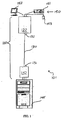
- FIG. 1 is a block diagram of a distance extender 100, according to an embodiment of the invention, shown as part of an electronic system 101. As illustrated in FIG. 1, distance extender 100 comprises a subsystem 110, a subsystem 120, and an electrical cable 130 electrically coupled between subsystems 110 and 120.
- distance extender 100 can be used to increase a distance between a device 145 and a device 150, where device 150 is in electrical communication with device 145.
- Subsystem 110 and/or subsystem 120 can comprise a stand-alone box, module, or the like, or subsystem 110 and/or subsystem 120 can comprise firmware implemented within a portion of device 145, device 150, and/or another component of distance extender 100.
- Electrical cable 130 has an end 131 and an end 132 opposite end 131.
- Subsystem 110 is electrically coupled to end 131 of electrical cable 130
- subsystem 120 is electrically coupled to end 132 of electrical cable 130.
- Electrical cable 130 further comprises a plurality of wires, including a first wire, extending between end 131 and end 132.
- electrical cable 130 further comprises at least a ground return wire.
- the first wire is one of a pair of wires, collectively referred to as a first wire pair, and the data signal and the electrical power signal are simultaneously transmitted between device 145 and device 150 over the first wire pair, in the sense that the electrical power signal and either the positive or negative portion of a differential data signal can be transmitted on the first wire, while the other wire in the first wire pair carries the ground return signal as well as the portion of the differential data signal not sent on the first wire.
- the data signal is bi-directional, meaning it travels along electrical cable 130 both from device 145 to device 150 as well as from device 150 to device 145.
- the data signal will most often be generated by device 150 and then travel across electrical cable 130 to device 145.
- the separate AC adapters or external power supplies required by existing KVM extenders, as well as the circuitry required to support the AC adapters or external power supplies, are not needed in distance extender 100, and are therefore absent from distance extender 100.
- the absence of AC adapters and external power supplies can be a significant advantage.
- AC adapters typically take up as much as two or three cubic inches.
- the outlets or power strips to which the AC adapters must be coupled also require relatively large amounts of space.
- the space required by the AC adapters and the outlets or power strips can often exceed the space available.
- electrical cable 130 comprises a plurality of unshielded, twisted wire pairs, one of which is the first wire pair described above.
- electrical cable 130 can be a Category 5 (CAT 5) cable, a Category 5e (CAT 5e) cable, a Category 6 (CAT 6) cable, a Category 7 (CAT 7) cable, or the like, collectively referred to herein as Category 5-type cable, each of which comprise four unshielded, twisted wire pairs.
- CAT 5 cable is a relatively inexpensive cable that is well suited for electrical signal transmission.
- the other existing cable types referred to above were developed to extend the bandwidth and function of the original CAT 5 specification.
- electrical cable 130 is a CAT 5 cable
- the data signal and the electrical power signal are simultaneously transmitted across the first wire pair, and red, green, and blue color analog signals are transmitted across the other three wire pairs.
- electrical cable 130 is electrically coupled between device 145 and device 150.
- Device 145 and/or device 150 generate data signal, and device 145 generates an electrical power signal, and the bi-directional data signal and the electrical power signal are simultaneously transmitted between device 145 and device 150 over the first wire.
- the data signal can comprise at least one of mouse data and keyboard data.
- device 145 can be a computer, and device 150 can be an OCC comprising a keyboard 151, a video monitor 152, and a mouse 153.
- subsystem 110, subsystem 120, keyboard 151, and mouse 153 are powered only by the electrical power signal.
- the electrical power signal can be taken from the positive (+) 5 volt (V) supply pins on the computer ports, such as the PS/2 ports, to which a keyboard or a mouse are normally connected.
- V voltage
- device 150 such as, for example, video monitor 152
- device 150 may require its own power supply when used in connection with distance extender 100, but any portion so requiring its own power supply is one that would also require its own power when used apart from distance extender 100.
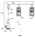
- FIG. 2 is a block diagram of a distance extender 200, according to an embodiment of the invention, shown as part of an electronic system 201 arranged in a first configuration
- distance extender 200 comprises a subsystem 210, a subsystem 220, and an electrical cable 230 electrically coupled between subsystems 210 and 220.
- subsystem 210, subsystem 220, and electrical cable 230 can be similar to subsystem 110, subsystem 120, and electrical cable 130, respectively, each of which were first shown in FIG. 1.
- Distance extender 200 further comprises a switch 240 electrically coupled between device 150 and device 145 as well as a device 245.
- device 245 can be similar to device 145, first shown in FIG. 1.
- switch 240 can be a KVM Switch.
- distance extender 200 can function in a manner similar to the function of distance extender 100 (FIG. 1).
- Switch 240 can be used to selectively route electrical signals to device 150 from one of devices 145, 245, or other device electrically coupled to switch 240, thus enabling any of devices 145, 245, or other device electrically coupled to switch 240 to be controlled from device 150.
- switch 240 is a KVM Switch
- device 150 is an OCC
- devices 145 and 245 are computers
- switch 240 routes video signals of the selected computer to the video monitor 152 of the OCC so that a user may view the video signals of the selected computer from the OCC.
- Switch 240 also routes keyboard and mouse signals from the OCC to the respective ports of the selected computer. By using switch 240 in this fashion, the selected computer can be operated from the OCC just as if the OCC's keyboard and mouse were directly attached to the selected computer.
- FIG. 1 illustrated the use of distance extender 100 to extend a distance separating device 145 from device 150, and, accordingly, subsystem 110 is electrically coupled to device 145 and subsystem 120 is electrically coupled to device 150.
- device 145 is a computer and device 150 is an OCC
- increasing a distance by which devices 145 and 150 are separated allows a situation in which the computer (device 145) can be located in a room where the environment is carefully controlled while the OCC (device 150) can be located in another room that can be made more comfortable for the user of the OCC.
- FIG. 1 illustrated the use of distance extender 100 to extend a distance separating device 145 from device 150, and, accordingly, subsystem 110 is electrically coupled to device 145 and subsystem 120 is electrically coupled to device 150.
- device 145 is a computer
- device 150 is an OCC
- FIG. 2 illustrates a slightly different configuration in which distance extender 200 is used to increase a distance separating device 150 from switch 240, wherein subsystem 210 is electrically coupled to switch 240 and subsystem 220 is electrically coupled to device 150.
- switch 240 and device 150 are located, for example, in different rooms, yielding a result similar to that described in connection with FIG. 1. Additional configurations are also possible, and desirable, as illustrated below.
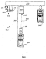
- FIG. 3 is a block diagram of distance extender 200 shown as part of electronic system 201 arranged in a second configuration
- FIG. 3 illustrates one of the possible additional configurations mentioned above, in which distance extender 200 is used to increase a distance separating device 145 from switch 240.
- subsystem 210 is electrically coupled to device 145
- subsystem 220 is electrically coupled to switch 240.
- switch 240 and device 150 may be located, for example, in different rooms.
- device 145 is a computer
- such a configuration may be desirable where the available space within, or the environment of, the room or other location in which switch 240 is located is not sufficient or suitable for the computer (device 145), or vice versa.
- a distance by which device 245 is separated from switch 240 can also be extended, using a second distance extender, where the second distance extender is the same or substantially similar to distance extender 200.
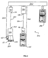
- FIG. 4 is a block diagram of distance extender 200 shown as part of electronic system 201 arranged in a third configuration.
- FIG. 4 illustrates another one of the possible additional configurations mentioned above, in which distance extenders according to embodiments of the invention are used to increase both a distance separating device 145 from switch 240 and a distance separating device 150 from switch 240.
- distance extender 200 is used to extend a distance separating device 150 from switch 240, such that subsystem 210 is electrically coupled to switch 240, and subsystem 220 is electrically coupled to device 150.
- a distance extender 400 is used to extend a distance separating device 145 from switch 240.
- Distance extender 400 comprises a subsystem 410, a subsystem 420, and an electrical cable 430.
- subsystem 410, subsystem 420, and electrical cable 430 can be similar to subsystem 110, subsystem 120, and electrical cable 130, respectively, each of which were first shown in FIG. 1.
- Subsystem 410 is electrically coupled to device 145
- subsystem 420 is electrically coupled to switch 240.
- FIG. 4 permits switch 240, device 145, and device 150 to each be located, for example, in different rooms.
- device 145 is a computer and device 150 is an OCC
- such a configuration may be desirable where the available space within, or the environment of, the room or other location in which switch 240 is located is not sufficient or suitable for the computer (device 145), and/or for the OCC (device 150), or vice versa.
- a distance by which device 245 is separated from switch 240 can also be extended, using an additional distance extender, where the additional distance extender is the same or substantially similar to distance extender 200.
- FIG. 5 is a block diagram of subsystem 110 of distance extender 100 (FIG. 1), according to an embodiment of the invention.
- subsystem 210 of distance extender 200 both of which were first shown in FIG. 2
- subsystem 410 of distance extender 400 both of which were first shown in FIG. 4
- subsystem 110 comprises a voltage boost circuit 510, a modulation/demodulation circuit 520, a filter circuit 530, a detection circuit 540, and a pre-emphasis circuit 551. Circuits 520, 530, 540, and 551 will each be described in more detail below.
- Subsystem 110 receives the data signal and a clock signal through an input header 560.
- the data and clock signals are routed directly to a microprocessor 565 where they are multiplexed and coded before being transmitted to modulation/demodulation circuit 520 via an internal Universal Asynchronous Receiver Transmitter (UART) 567.
- UART Universal Asynchronous Receiver Transmitter
- Power for the circuitry of subsystem 110 is taken from the +5V supply pins on the PS/2 ports of the computer. Electrical power signals enter subsystem 110 through input header 560 and are passed to voltage boost circuit 510 and to a local power supply 515. Local power supply 515 supplies five volts or another voltage to the circuitry of subsystem 110. Voltage boost circuit 510 boosts the incoming voltage from 5V to a higher voltage in order to overcome and/or compensate for losses, such as IR losses, in electrical cable 130 (FIGs. 1-4) during the transmission of the electrical power signal across electrical cable 130. As an example, voltage boost circuit 510 can boost the incoming voltage to 30V. The electrical power signal, with boosted voltage, is passed to modulation/demodulation circuit 520, where it will be combined with the coded data signal as described below.
- input header 560 also receives video signals, comprising red, green, and blue video signals, and synchronization signals (sync signals) in addition to receiving data, clock, and electrical power signals.
- the sync signals are mixed, or multiplexed, into the video signals, and the resulting combined signals (comprising video signals and sync signals) are amplified by a video amplifier 550, passed into end 131 of electrical cable 130 (FIGs. 1-4) and transmitted differentially along electrical cable 130.
- the sync signals are mixed into the red and blue video signals only, amplified, and differentially transmitted.
- connector 131 is an RJ45 connector.
- Pre-emphasis circuit 551 in at least one embodiment, forms a part of video amplifier 550.
- Pre-emphasis circuit 551 pre-emphasizes, or increases, the high-frequency portion of the video signals before the video signals are transmitted across electrical cable 130 because higher frequency video signals are attenuated during such transmission to a greater extent than are lower frequency signals. Pre-emphasizing the high-frequency portion of the video signals in this way makes it easier to recover those signals after they have arrived at subsystem 120 (FIG. 1).
- the data signal After passing through microprocessor 565 and UART 567, the data signal is passed through a data modem 570 and then to modulation/demodulation circuit 520 where it is modulated and coupled onto the boosted voltage.
- the combined signal comprising: (1) the power signal with the boosted electrical voltage signal; and (2) the data signal, is then sent to filter circuit 530 and then to end 131 of electrical cable 130 (FIGs. 1-4) before being sent across electrical cable 130.
- Filter circuit 530 prevents the data signal from interfering with power supply 515, as will be discussed in more detail below.
- FIG. 6 is a block diagram of subsystem 120 of distance extender 100 (FIG. 1), according to an embodiment of the invention.
- subsystem 220 of distance extender 200 both of which were first shown in FIG. 2
- subsystem 420 of distance extender 400 both of which were first shown in FIG. 4
- subsystem 120 can be the same or substantially similar to subsystem 120.
- subsystem 120 comprises a voltage conversion circuit 610, a modulation/demodulation circuit 620, a filter circuit 630, and an attenuation compensation circuit 651.
- a power supply 615 supplies power for the circuitry of subsystem 120.
- modulation/demodulation circuit 620 can be similar to modulation/demodulation circuit 520 (FIG. 5)
- filter circuit 630 can be similar to filter circuit 530 (FIG. 5).
- Circuit 651 will be described in more detail below. Circuits 620 and 630 will not be separately described because of their similarity to circuits 520 and 530, respectively.
- multiplexed differential video and sync signals are received through end 132, which can be an RJ45 connector, of electrical cable 130 (FIGs. 1-4) and passed to a video amplifier 650.
- differential-to-single-ended amplifiers within video amplifier 650 receive the multiplexed differential video and sync signals.
- the sync signals are mixed into the red and blue video signals
- the red and blue video signals are routed to a sync stripper circuit 670 and a sync detection and polarization circuit 690 before being sent to a connector 680.
- Sync detection and polarization circuit 690 recovers the sync polarity from the original video signals, and the polarity-corrected sync signals are sent to connector 680.
- connector 680 can be an HDDB 15 connector.
- the sync signals are mixed onto the red and blue video signals
- the green video is routed directly from the differential-to-single-ended amplifiers to connector 680.
- Subsystem 120 also receives the combined signal through end 132 and passes the combined signal through filter circuit 630 to voltage conversion circuit 610 and modulation/demodulation circuit 620.
- Filter circuit 630 prevents the modulated data signal from interfering with the circuitry of power supply 615.
- Voltage conversion circuit 610 converts the boosted voltage to a lower voltage, which in at least one embodiment can be 5V, which lower voltage is passed to power supply 615 and used to power the circuitry of subsystem 120.
- Modulation/demodulation circuit 620 demodulates the data signal.
- the demodulated data signal is then sent to a UART 667 on microprocessor 665 where the demodulated data signal is separated into keyboard and mouse data signals and sent to the appropriate one of ports 695.
- ports 695 can be PS/2 ports, one of which can receive a keyboard and the other of which can receive a mouse.
- FIG. 7 is a circuit diagram of modulation/demodulation circuit 520 according to an embodiment of the invention.
- FIG. 8 is a graph 800 of an amplitude-modulated signal of the type produced by modulation/demodulation circuit 520 according to an embodiment of the invention.
- FIG. 9 is a graph 900 of an amplitude-modulated signal of the type shown in FIG. 8 riding on a boosted electrical voltage signal according to an embodiment of the invention.
- FIG. 10 is a graph 1000 showing a recovered signal after being modulated and demodulated according to an embodiment of the invention.
- the data signal is routed from input header 560 to microprocessor 565, where the data signal is multiplexed and coded prior to being sent to modulation/demodulation circuit 520.
- the coded data signal is then transmitted by data UART 567 through data modem 570 to modulation/demodulation circuit 520.
- the data signal enters modulation/demodulation circuit 520 on a line 701, and is labeled "data_from_controller.”
- the data line is a single-ended square wave 0 to 5V signal. A logic “1" is indicated by a 5 volt direct current (DC) level and a logic "0" is indicated by a 0 volt DC level.
- This signal is inverted and applied to pin 3 of a transceiver 710, which in the illustrated embodiment is an RS485 transceiver.
- Pin 3 of transceiver 710 is an enable pin.
- a one megahertz (MHz) signal is applied to the data input of transceiver 710. Whenever pin 3 of transceiver 710 is high the one MHz signal is passed through transceiver 710 to the differential outputs present on pin 6 and pin 7 of transceiver 710.
- the resultant waveform on pin 6 of transceiver 710 is an amplitude-modulated signal of the type shown in FIG. 8.
- transceiver 710 Since the output of transceiver 710 is a differential signal, the same signal is present on pin 7 of transceiver 710, except that the signal on pin 7 of transceiver 710 is 180 degrees out of phase with the signal on pin 6 of transceiver 710.
- a 110 ohm resistor, R35 loads the differential signals present at pins 6 and 7 of transceiver 710.
- Resisters R32, R33, R37, and R38 bias pins 6 and 7 of transceiver 710 so that the steady state level of pin 1 of transceiver 710 is a logical "0."
- the signals present at pins 6 and 7 of transceiver 710 are AC coupled through capacitors C33 and C35 to connector pins 7and 8 of end 131, which is illustrated as an RJ45 connector in FIG. 7.
- Resistors R51 and R54 and capacitors C33 and C35 are used to match the differential signal to the impedance of electrical cable 130 (FIGs. 1-4) and to the receiver input impedance.
- graph 800 comprises a channel 810 and a channel 820.
- Channel 810 represents data input on line 701 (FIG. 7) of modulation/demodulation circuit 520 (FIGs. 5 and 7).
- Channel 820 represents an amplitude-modulated signal such as may be present on pin 6 or pin 7 of transceiver 710.
- Graph 900 comprises a channel 910 and a channel 920.
- Channel 910 represents data input on line 701 (FIG. 7) of modulation/demodulation circuit 520 (FIGs. 5 and 7).
- Channel 920 represents modulated data riding on an electrical power signal having a boosted voltage of 30 volts.
- the modulated data signal and the boosted electrical voltage signal are simultaneously carried on a single wire pair in electrical cable 130 (FIGs. 1-4).
- pins 7 and 8 of end 131, shown in FIG. 7, correspond to the two wires of the single wire pair on which the combined signal is carried. In a CAT 5 cable, the two wires form a twisted wire pair, as mentioned above.
- the modulated differential signal is received at pins 6 and 7 of transceiver 710.
- Transceiver 710 converts this signal to a single-ended output on pin 1 of transceiver 710.
- An example of the type of single-ended output that may be on pin 1 of transceiver 710 is illustrated in a graph 1000 of FIG. 10. Referring still to FIG. 7, the single-ended output is demodulated using a diode D3, a capacitor C34, and a resistor R34. The signal is inverted and then input to data UART 567 of microprocessor 565.
- graph 1000 comprises a channel 1010 and a channel 1020.
- Channel 1010 represents a modulated data signal such as may be received on pin 1 of transceiver 710.
- Channel 1020 represents a recovered signal present at an output of a buffer 720, which buffer is labeled "Data_Input To_Controller" in FIG. 7.
- FIG. 11 is a circuit diagram illustrating a portion of modulation/demodulation circuit 520 and a filter circuit 530 according to an embodiment of the invention.
- Filter circuit 530 prevents the one MHz signal (first discussed in connection with FIG. 7) from interfering with power supply 515 and the circuitry of subsystem 110.
- the data signal is coupled onto the connector pins 7 and 8 of end 131 through capacitors C33 and C35.
- the data signal is blocked from the power of power supply 515 and from the ground signals by inductors L4, L2, L3, and L1, and by a capacitor C46.
- inductors L4, L2, L3, and L1 inductors
- the modulated data signal is riding on the boosted voltage power line, and on the ground line, but is prevented from back-feeding into power supply 515 by filter circuit 530.
- filter circuit 630 (FIG. 6) of subsystem 120 is the same or substantially similar to filter circuit 530. Accordingly, the data signal can be transmitted bi-directionally down a single twisted pair of a CAT5 cable or other electrical cable 130 (FIGs. 1-4) and the DC voltage can be delivered to subsystem 120 on the same twisted pair without interfering with the circuitry of subsystem 110 or subsystem 120.
- FIG. 12 is a circuit diagram illustrating detection circuit 540.
- a portion 1210 of detection circuit 540 is located on subsystem 110, and a portion 1220 of detection circuit 540 is located on subsystem 120.
- Subsystem 110 only applies the 5V DC "logic '1'" signal to pin 7 of end 131 until it is determined that subsystem 120 is connected.
- subsystem 110 enables voltage boost circuit 510 which supplies boosted voltage to pin 7 of end 131 (FIG. 1) which in FIG. 12 is illustrated as an RJ45 connector.
- the detection mechanism of detection circuit 540 comprises a simple circuit to designed to detect that a correct load is attached to the wire pair carrying the combined data and power signal As illustrated in FIG.
- 5V DC is applied through a diode D1 and a resistor R59 to pin 7 of the RJ45 connector.
- resistors R59 and R62 form a voltage divider to ground.
- a transistor Q2 turned on by the "CNTR_5V_32V_SELECT" signal, a transistor Q1 passes the voltage at the node of resistors R59 and R62 to the ADC input pin on microprocessor 665 (FIG. 6) of subsystem 120.
- Microprocessor 665 samples this voltage and, if it is within a predetermined range, transistor Q2 is turned off and the boosted voltage will be applied to pin 7 of the RJ45 connector.
- subsystem 120 is not connected to subsystem 110, or if subsystem 110 is connected to a network device, such as a hub, a switch, a router, or the like, the voltage at the node of resistors R59 and R62 will not be in the predetermined acceptable range, and the boosted voltage will not be enabled.
- a network device such as a hub, a switch, a router, or the like
- FIG. 13 is a circuit diagram illustrating pre-emphasis circuit 551, which is designed to emphasize the high frequency component of the video signals, before such signals are transmitted, in anticipation of the high frequency attenuation that occurs over long lengths of electrical cable 130 (FIGs. 1-4).
- capacitors C51 and C52 and resistors R69 and R70 are switched into the feedback leg of a differential driver U6 by a transistor Q6.
- Capacitors C51 and C52 and resistors R69 and R70 give a low impedance feedback path for high frequencies, thus peaking the gain of the high frequency components in the amplifier.
- a switch on subsystem 120 ultimately controls transistor Q6.
- the switch is read by microprocessor 665 of subsystem 120, and the status of the switch is transmitted back to subsystem 110 over wire pair carrying the combined data and power signal Capacitors C17 and C27 and resistors R63 and R64 are also used to adjust the amplifier frequency response.
- FIG. 14 is a circuit diagram illustrating attenuation/compensation circuit 651.
- subsystem 120 accepts the differential video signals from subsystem 110, amplifies the video signals, and outputs a signal-ended video signal to connector 680 (FIG. 4).
- the higher frequency components of the video signals are increasingly more attenuated during their transmission along electrical cable 130, as discussed above.
- a series resistor and capacitor are placed in parallel with a gain resistor R20 of the differential-to-signal-ended amplifier that form a part of video amplifier 650 (FIG. 6). In this way, various compensation legs can be switched into the feedback path.
- a resistor R61 and a capacitor C48, a resistor R60 and a capacitor C47, and a resistor R59 and a capacitor C46 respectively form the three resistor-capacitor (RC) pairs.
- a microprocessor control signal enables or disables one RC pair at a time depending on a user control switch read by microprocessor 665.
- These capacitors and resistors give a low impedance feedback path for high frequencies, thus peaking the gain of the high frequency components in the amplifier. The range of frequencies that are peaked and the final gain is dependent on the RC pair that is switched in parallel with gain resistor R20. In this way compensation for attenuation of high frequencies in electrical cable 130 (FIGs. 1-4) is accomplished for varying lengths of electrical cable 130.
- FIG. 15 is a flow chart illustrating a method 1500 for increasing a distance between a computer and an operator control center in electrical communication with the computer, where the electrical communication is accomplished via a cable having a first wire pair and a second wire pair.
- a step 1510 of method 1500 is to provide a first subsystem to be coupled to a first end of the cable.
- the cable can be similar to electrical cable 130
- the computer can be similar to device 145
- the operator control center can be similar to device 150, all of which were first shown in FIG. 1.
- the first subsystem can be similar to subsystem 110, also first shown in FIG. 1.
- a step 1520 of method 1500 is to provide a second subsystem to be coupled to a second end of the cable such that an electrical power signal provided by the computer and a data signal generated by the computer or the operator control center are transmitted simultaneously across the first wire pair between the computer and the operator control center.
- the second subsystem can be similar to subsystem 120, first shown in FIG. 1.
- a step 1530 of method 1500 is to modulate the data signal to create a modulated data signal
- the modulated data signal can be similar to the signal shown on channel 820 in FIG. 8.
- the modulated data signal can be created using modulation/demodulation circuit 520, first shown in FIG. 5, or modulation/demodulation circuit 620, first shown in FIG. 6.
- a step 1540 of method 1500 is to modify the electrical power signal to create a boosted electrical voltage signal.
- the boosted electrical voltage signal can be created using voltage boost circuit 510.
- a step 1550 of method 1500 is to couple the modulated data signal onto the boosted electrical power voltage to create a combined signal
- the combined signal can be similar to the signal shown on channel 920 in FIG. 9.
- a step 1560 of method 1500 is to transmit the combined signal across the first wire pair between the computer and the operator control center.
- step 1530 or another step can further comprise using the computer to generate a video signal
- step 1560 or another step can further comprise transmitting the video signal across the second wire pair between the computer and the operator control center.
- step 1560 or another step further comprises demodulating the modulated data signal after transmitting the modulated data signal across the first wire pair, and/or reducing the boosted electrical voltage signal after transmitting the boosted electrical voltage signal across the first wire pair.
- step 1560 or another step further comprises compensating for attenuation of the video signal before transmitting the video signal across the second wire pair and /or compensating for attenuation of the video signal after transmitting the video signal across the second wire pair.
- step 1560 or another step further comprises filtering the combined signal to prevent the modulated data signal from interfering with the boosted electrical voltage signal.
- step 1560 or another step further comprises detecting the presence of the second subsystem at the first subsystem before enabling the electrical power signal.
- step 1510 or another step further comprises providing a switch and electrically coupling the switch between the computer and the operator control center.
- the switch can be similar to switch 240, first shown in FIG. 2.
- step 1510 or another step further comprises: (1) electrically coupling the switch between the computer and the first subsystem; and (2) electrically coupling the second subsystem between the first subsystem and the operator control center.
- step 1510 or another step further comprises: (1) electrically coupling the switch between the second subsystem and the operator control center; and (2) electrically coupling the first subsystem between the computer and the second subsystem.
- step 1510 or another step further comprises: (1) providing a third subsystem substantially similar to the first subsystem; (2) providing a fourth subsystem substantially similar to the second subsystem; (3) electrically coupling the third subsystem between the switch and the fourth subsystem; (4) electrically coupling the fourth subsystem between the third subsystem and the operator control center; and (5) electrically coupling the switch between the second subsystem and the third subsystem.
- embodiments and limitations disclosed herein are not dedicated to the public under the doctrine of dedication if the embodiments and/or limitations: (1) are not expressly claimed in the claims; and (2) are or are potentially equivalents of express elements and/or limitations in the claims under the doctrine of equivalents.
Abstract
Description
- This invention relates generally to electrical signal transmission in electronic systems, and relates more particularly to keyboard, video, and mouse extenders.
- Electronic systems, such as computer systems, rely for proper operation on the transmission of electronic signals among the various components of the system. In a computer system, for example, electronic signals must be transmitted from the computer to a keyboard, a video monitor, a mouse, and any other peripheral electronic devices coupled to the computer. The acronym KVM will be used herein to mean "keyboard, video monitor, and mouse," following a practice that is standard in the art. Additionally, the phrase "peripheral device" will be used herein to mean any electronic device coupled to a computer or forming a part of any electronic system, including a keyboard, a video monitor, and a mouse.
- Under certain circumstances it may be desirable to place the computer in one location and to place the peripheral devices in another location separated from the computer's location by a certain distance. An example of such a circumstance is where the computer must be in an environment, perhaps a particular room in a building, where parameters such as access, temperature, humidity, and the like are carefully controlled but where the peripheral devices may be located in an environment, perhaps another room in the building, where control over such parameters is less critical. Another example of such a circumstance is where a single keyboard, video monitor, and mouse, referred to collectively herein as an "operator control center" or an "OCC," are adapted to control several computers, where the several computers may be located at a distance from the operator control center.
- KVM extenders have been developed in order to increase the distance by which an operator control center can be separated from a computer. Existing KVM extenders include a local subsystem, a remote subsystem, and a cable coupled between the local and remote subsystems. The local subsystem is coupled to a computer and/or, if applicable, to a KVM Switch that switches control from one to another of several computers being controlled by an operator control center. The remote subsystem is coupled to the OCC. Electronic signals may be transmitted between the computer and the OCC across the cable via the local and remote subsystems.
- Both the local and remote subsystems of existing KVM extenders require the use of power supplies, alternating current (AC) adapters, or the like to provide power to the subsystems. Such power supplies, AC adapters, and the like are bulky and take up a significant amount of space. In many environments, such as in a server rack or in an environmentally controlled room, space is at a premium, and the presence of a power supply or an AC adapter is an inefficient use of that space. Accordingly, there exists a need for a KVM extender providing all of the functionality of existing KVM extenders but that does not require a separate power supply or AC adapter.
- The invention will be better understood from a reading of the following detailed description, taken in conjunction with the accompanying figures in the drawings in which:
- FIG. 1 is a block diagram of a distance extender, according to an embodiment of the invention, shown as part of an electronic system;
- FIG. 2 is a block diagram of a distance extender, according to another embodiment of the invention, shown as part of a different electronic system arranged in a first configuration;
- FIG. 3 is a block diagram of the distance extender of FIG. 2 shown as part of the electronic system of FIG. 2 arranged in a second configuration;
- FIG. 4 is a block diagram of the distance extender of FIG. 2 shown as part of the electronic system of FIG. 2 arranged in a third configuration;
- FIG. 5 is a block diagram of a subsystem of the distance extenders of FIGs. 1 and 2, according to an embodiment of the invention;
- FIG. 6 is a block diagram of a different subsystem of the distance extenders of FIGs. 1 and 2, according to an embodiment of the invention;
- FIG. 7 is a circuit diagram of a modulation/demodulation circuit according to an embodiment of the invention;
- FIG. 8 is a graph of an amplitude-modulated signal of the type produced by the modulation/demodulation circuit of FIG. 7 according to an embodiment of the invention;
- FIG. 9 is a graph of an amplitude-modulated signal of the type shown in FIG. 8 riding on a boosted electrical voltage signal according to an embodiment of the invention;
- FIG. 10 is a graph showing a recovered signal after being modulated and demodulated according to an embodiment of the invention;
- FIG. 11 is a circuit diagram illustrating a portion of the modulation/demodulation circuit of FIG. 7 and a filter circuit according to an embodiment of the invention;
- FIG. 12 is a circuit diagram illustrating a detection circuit according to an embodiment of the invention;
- FIG. 13 is a circuit diagram illustrating a pre-emphasis circuit according to an embodiment of the invention;
- FIG. 14 is a circuit diagram illustrating an attenuation/compensation circuit according to an embodiment of the invention; and
- FIG. 15 is a flow chart illustrating a method for increasing a distance between a computer and an operator control center in electrical communication with the computer.
-
- For simplicity and clarity of illustration, the drawing figures illustrate the general manner of construction, and descriptions and details of well-known features and techniques may be omitted to avoid unnecessarily obscuring the invention Additionally, elements in the drawing figures are not necessarily drawn to scale. For example, the dimensions of some of the elements in the figures may be exaggerated relative to other elements to help improve understanding of embodiments of the present invention The same reference numerals in different figures denote the same elements.
- The terms "first," "second," "third," "fourth," and the like in the description and in the claims, if any, are used for distinguishing between similar elements and not necessarily for describing a particular sequential or chronological order. It is to be understood that the terms so used are interchangeable under appropriate circumstances such that the embodiments of the invention described herein are, for example, capable of operation in sequences other than those illustrated or otherwise described herein. Furthermore, the terms "comprise," "include," "have," and any variations thereof, are intended to cover a non-exclusive inclusion, such that a process, method, article, or apparatus that comprises a list of elements is not necessarily limited to those elements, but may include other elements not expressly listed or inherent b such process, method, article, or apparatus.
- The terms "left," "right," "front," "back," "top," "bottom," "over," "under," and the like in the description and in the claims, if any, are used for descriptive purposes and not necessarily for describing permanent relative positions. It is to be understood that the terms so used are interchangeable under appropriate circumstances such that the embodiments of the invention described herein are, for example, capable of operation in other orientations than those illustrated or otherwise described herein. The term "coupled," as used herein, is defined as directly or indirectly connected in an electrical, mechanical, or other manner.
- In one embodiment of the invention, a distance extender for increasing a distance between a first device and a second device in electrical communication with the first device comprises an electrical cable electrically coupled between the first device and the second device, a first subsystem electrically coupled to the first end of the electrical cable, and a second subsystem electrically coupled to the second end of the electrical cable. The electrical cable comprises a first end, a second end, and a plurality of wires extending between the first end and the second end. The plurality of wires includes a first wire, the first device generates a data signal and provides an electrical power signal, and the data signal and the electrical power signal are simultaneously transmitted between the first device and the second device over the first wire.
- FIG. 1 is a block diagram of a
distance extender 100, according to an embodiment of the invention, shown as part of anelectronic system 101. As illustrated in FIG. 1,distance extender 100 comprises asubsystem 110, asubsystem 120, and anelectrical cable 130 electrically coupled betweensubsystems - As an example,
distance extender 100 can be used to increase a distance between adevice 145 and adevice 150, wheredevice 150 is in electrical communication withdevice 145.Subsystem 110 and/orsubsystem 120 can comprise a stand-alone box, module, or the like, orsubsystem 110 and/orsubsystem 120 can comprise firmware implemented within a portion ofdevice 145,device 150, and/or another component ofdistance extender 100.Electrical cable 130 has anend 131 and anend 132opposite end 131.Subsystem 110 is electrically coupled toend 131 ofelectrical cable 130, andsubsystem 120 is electrically coupled toend 132 ofelectrical cable 130.Electrical cable 130 further comprises a plurality of wires, including a first wire, extending betweenend 131 andend 132. - As will be understood by one having ordinary skill in the art,
electrical cable 130 further comprises at least a ground return wire. In at least one embodiment, the first wire is one of a pair of wires, collectively referred to as a first wire pair, and the data signal and the electrical power signal are simultaneously transmitted betweendevice 145 anddevice 150 over the first wire pair, in the sense that the electrical power signal and either the positive or negative portion of a differential data signal can be transmitted on the first wire, while the other wire in the first wire pair carries the ground return signal as well as the portion of the differential data signal not sent on the first wire. - It will be understood by one of ordinary skill in the art that the data signal is bi-directional, meaning it travels along
electrical cable 130 both fromdevice 145 todevice 150 as well as fromdevice 150 todevice 145. In an embodiment wheredevice 150 is an OCC anddevice 145 is a computer, the data signal will most often be generated bydevice 150 and then travel acrosselectrical cable 130 todevice 145. - Because the electrical power signal is transmitted, as described, across the first wire pair of
electrical cable 130, the separate AC adapters or external power supplies required by existing KVM extenders, as well as the circuitry required to support the AC adapters or external power supplies, are not needed indistance extender 100, and are therefore absent fromdistance extender 100. For a variety of reasons, the absence of AC adapters and external power supplies can be a significant advantage. As an example, AC adapters typically take up as much as two or three cubic inches. The outlets or power strips to which the AC adapters must be coupled also require relatively large amounts of space. Especially in an environment where multiple KVM extenders are present, such as in a server rack or server room, the space required by the AC adapters and the outlets or power strips can often exceed the space available. Another advantage of the absence of AC adapters and external power supplies is that any concern as to whether an AC adapter will fall out of a wall outlet, power strip, or other electrical outlet may be eliminated. Yet another advantage is that there is no need to take time to physically plug such AC adapters in to an electrical outlet. - In a particular embodiment,
electrical cable 130 comprises a plurality of unshielded, twisted wire pairs, one of which is the first wire pair described above. As an example,electrical cable 130 can be a Category 5 (CAT 5) cable, a Category 5e (CAT 5e) cable, a Category 6 (CAT 6) cable, a Category 7 (CAT 7) cable, or the like, collectively referred to herein as Category 5-type cable, each of which comprise four unshielded, twisted wire pairs. CAT 5 cable is a relatively inexpensive cable that is well suited for electrical signal transmission. The other existing cable types referred to above were developed to extend the bandwidth and function of the original CAT 5 specification. In at least one embodiment whereelectrical cable 130 is a CAT 5 cable, the data signal and the electrical power signal are simultaneously transmitted across the first wire pair, and red, green, and blue color analog signals are transmitted across the other three wire pairs. - As further illustrated in FIG. 1,
electrical cable 130 is electrically coupled betweendevice 145 anddevice 150.Device 145 and/ordevice 150 generate data signal, anddevice 145 generates an electrical power signal, and the bi-directional data signal and the electrical power signal are simultaneously transmitted betweendevice 145 anddevice 150 over the first wire. As an example, the data signal can comprise at least one of mouse data and keyboard data. As another example,device 145 can be a computer, anddevice 150 can be an OCC comprising akeyboard 151, avideo monitor 152, and amouse 153. - In at least one embodiment,
subsystem 110,subsystem 120,keyboard 151, andmouse 153 are powered only by the electrical power signal. As an example, in an embodiment wheredevice 145 is a computer, the electrical power signal can be taken from the positive (+) 5 volt (V) supply pins on the computer ports, such as the PS/2 ports, to which a keyboard or a mouse are normally connected. The simultaneous transmission of the electrical power signal and the data signal betweendevice 145 anddevice 150 across the first wire pair will be discussed in more detail below. It will be understood by one of ordinary skill in the art that at least a portion ofdevice 150, such as, for example,video monitor 152, may require its own power supply when used in connection withdistance extender 100, but any portion so requiring its own power supply is one that would also require its own power when used apart fromdistance extender 100. - FIG. 2 is a block diagram of a
distance extender 200, according to an embodiment of the invention, shown as part of anelectronic system 201 arranged in a first configuration As illustrated in FIG. 2,distance extender 200 comprises asubsystem 210, asubsystem 220, and anelectrical cable 230 electrically coupled betweensubsystems subsystem 210,subsystem 220, andelectrical cable 230 can be similar tosubsystem 110,subsystem 120, andelectrical cable 130, respectively, each of which were first shown in FIG. 1.Distance extender 200 further comprises aswitch 240 electrically coupled betweendevice 150 anddevice 145 as well as adevice 245. As an example,device 245 can be similar todevice 145, first shown in FIG. 1. Additional devices, all of which can also be similar todevice 145, can also form a part ofelectronic system 201, and can also be electrically coupled to switch 240, depending on the configuration and capacity ofswitch 240. As an example, switch 240 can be a KVM Switch. As another example,distance extender 200 can function in a manner similar to the function of distance extender 100 (FIG. 1). - Switch 240 can be used to selectively route electrical signals to
device 150 from one ofdevices devices device 150. As an example, in an embodiment whereswitch 240 is a KVM Switch,device 150 is an OCC, anddevices video monitor 152 of the OCC so that a user may view the video signals of the selected computer from the OCC. Switch 240 also routes keyboard and mouse signals from the OCC to the respective ports of the selected computer. By usingswitch 240 in this fashion, the selected computer can be operated from the OCC just as if the OCC's keyboard and mouse were directly attached to the selected computer. - The need to extend a distance separating various components of electronic systems has been mentioned above. FIG. 1 illustrated the use of
distance extender 100 to extend adistance separating device 145 fromdevice 150, and, accordingly,subsystem 110 is electrically coupled todevice 145 andsubsystem 120 is electrically coupled todevice 150. In an embodiment wheredevice 145 is a computer anddevice 150 is an OCC, increasing a distance by whichdevices distance extender 200 is used to increase adistance separating device 150 fromswitch 240, whereinsubsystem 210 is electrically coupled to switch 240 andsubsystem 220 is electrically coupled todevice 150. Such a configuration permits switch 240 anddevice 150 to be located, for example, in different rooms, yielding a result similar to that described in connection with FIG. 1. Additional configurations are also possible, and desirable, as illustrated below. - FIG. 3 is a block diagram of
distance extender 200 shown as part ofelectronic system 201 arranged in a second configuration FIG. 3 illustrates one of the possible additional configurations mentioned above, in whichdistance extender 200 is used to increase adistance separating device 145 fromswitch 240. In the configuration of FIG. 3,subsystem 210 is electrically coupled todevice 145, andsubsystem 220 is electrically coupled to switch 240. Such a configuration permits switch 240 anddevice 150 to be located, for example, in different rooms. In an embodiment wheredevice 145 is a computer, such a configuration may be desirable where the available space within, or the environment of, the room or other location in which switch 240 is located is not sufficient or suitable for the computer (device 145), or vice versa. In one embodiment, not illustrated in FIG. 3, a distance by whichdevice 245 is separated fromswitch 240 can also be extended, using a second distance extender, where the second distance extender is the same or substantially similar todistance extender 200. - FIG. 4 is a block diagram of
distance extender 200 shown as part ofelectronic system 201 arranged in a third configuration. FIG. 4 illustrates another one of the possible additional configurations mentioned above, in which distance extenders according to embodiments of the invention are used to increase both adistance separating device 145 fromswitch 240 and adistance separating device 150 fromswitch 240. As illustrated in FIG. 4,distance extender 200 is used to extend adistance separating device 150 fromswitch 240, such thatsubsystem 210 is electrically coupled to switch 240, andsubsystem 220 is electrically coupled todevice 150. Adistance extender 400 is used to extend adistance separating device 145 fromswitch 240.Distance extender 400 comprises a subsystem 410, asubsystem 420, and anelectrical cable 430. As an example, subsystem 410,subsystem 420, andelectrical cable 430 can be similar tosubsystem 110,subsystem 120, andelectrical cable 130, respectively, each of which were first shown in FIG. 1. Subsystem 410 is electrically coupled todevice 145, andsubsystem 420 is electrically coupled to switch 240. - The configuration of FIG. 4 permits switch 240,
device 145, anddevice 150 to each be located, for example, in different rooms. In an embodiment wheredevice 145 is a computer anddevice 150 is an OCC, such a configuration may be desirable where the available space within, or the environment of, the room or other location in which switch 240 is located is not sufficient or suitable for the computer (device 145), and/or for the OCC (device 150), or vice versa. In one embodiment, not illustrated in FIG. 4, a distance by whichdevice 245 is separated fromswitch 240 can also be extended, using an additional distance extender, where the additional distance extender is the same or substantially similar todistance extender 200. - FIG. 5 is a block diagram of
subsystem 110 of distance extender 100 (FIG. 1), according to an embodiment of the invention. As stated above, in at least one embodiment,subsystem 210 ofdistance extender 200, both of which were first shown in FIG. 2, and subsystem 410 ofdistance extender 400, both of which were first shown in FIG. 4, can be the same or substantially similar tosubsystem 110. As illustrated in FIG. 5,subsystem 110 comprises avoltage boost circuit 510, a modulation/demodulation circuit 520, afilter circuit 530, adetection circuit 540, and apre-emphasis circuit 551.Circuits - The following description assumes an embodiment where
device 150 is a computer.Subsystem 110 receives the data signal and a clock signal through aninput header 560. The data and clock signals are routed directly to amicroprocessor 565 where they are multiplexed and coded before being transmitted to modulation/demodulation circuit 520 via an internal Universal Asynchronous Receiver Transmitter (UART) 567. - Power for the circuitry of
subsystem 110 is taken from the +5V supply pins on the PS/2 ports of the computer. Electrical power signals entersubsystem 110 throughinput header 560 and are passed tovoltage boost circuit 510 and to a local power supply 515. Local power supply 515 supplies five volts or another voltage to the circuitry ofsubsystem 110.Voltage boost circuit 510 boosts the incoming voltage from 5V to a higher voltage in order to overcome and/or compensate for losses, such as IR losses, in electrical cable 130 (FIGs. 1-4) during the transmission of the electrical power signal acrosselectrical cable 130. As an example,voltage boost circuit 510 can boost the incoming voltage to 30V. The electrical power signal, with boosted voltage, is passed to modulation/demodulation circuit 520, where it will be combined with the coded data signal as described below. - As illustrated in FIG. 5,
input header 560 also receives video signals, comprising red, green, and blue video signals, and synchronization signals (sync signals) in addition to receiving data, clock, and electrical power signals. The sync signals are mixed, or multiplexed, into the video signals, and the resulting combined signals (comprising video signals and sync signals) are amplified by avideo amplifier 550, passed intoend 131 of electrical cable 130 (FIGs. 1-4) and transmitted differentially alongelectrical cable 130. In one embodiment, the sync signals are mixed into the red and blue video signals only, amplified, and differentially transmitted. In the same or another embodiment,connector 131 is an RJ45 connector.Pre-emphasis circuit 551, in at least one embodiment, forms a part ofvideo amplifier 550.Pre-emphasis circuit 551 pre-emphasizes, or increases, the high-frequency portion of the video signals before the video signals are transmitted acrosselectrical cable 130 because higher frequency video signals are attenuated during such transmission to a greater extent than are lower frequency signals. Pre-emphasizing the high-frequency portion of the video signals in this way makes it easier to recover those signals after they have arrived at subsystem 120 (FIG. 1). - After passing through
microprocessor 565 and UART 567, the data signal is passed through a data modem 570 and then to modulation/demodulation circuit 520 where it is modulated and coupled onto the boosted voltage. The combined signal, comprising: (1) the power signal with the boosted electrical voltage signal; and (2) the data signal, is then sent to filtercircuit 530 and then to end 131 of electrical cable 130 (FIGs. 1-4) before being sent acrosselectrical cable 130.Filter circuit 530 prevents the data signal from interfering with power supply 515, as will be discussed in more detail below. - FIG. 6 is a block diagram of
subsystem 120 of distance extender 100 (FIG. 1), according to an embodiment of the invention. As stated above, in at least one embodiment,subsystem 220 ofdistance extender 200, both of which were first shown in FIG. 2, andsubsystem 420 ofdistance extender 400, both of which were first shown in FIG. 4, can be the same or substantially similar tosubsystem 120. - As illustrated in FIG. 6,
subsystem 120 comprises avoltage conversion circuit 610, a modulation/demodulation circuit 620, a filter circuit 630, and anattenuation compensation circuit 651. Apower supply 615 supplies power for the circuitry ofsubsystem 120. As an example, modulation/demodulation circuit 620 can be similar to modulation/demodulation circuit 520 (FIG. 5), and filter circuit 630 can be similar to filter circuit 530 (FIG. 5).Circuit 651 will be described in more detail below. Circuits 620 and 630 will not be separately described because of their similarity tocircuits - As further illustrated in FIG. 6, multiplexed differential video and sync signals are received through
end 132, which can be an RJ45 connector, of electrical cable 130 (FIGs. 1-4) and passed to avideo amplifier 650. In one embodiment, differential-to-single-ended amplifiers withinvideo amplifier 650 receive the multiplexed differential video and sync signals. In an embodiment where the sync signals are mixed into the red and blue video signals, the red and blue video signals are routed to a sync stripper circuit 670 and a sync detection andpolarization circuit 690 before being sent to aconnector 680. Sync detection andpolarization circuit 690 recovers the sync polarity from the original video signals, and the polarity-corrected sync signals are sent toconnector 680. As an example,connector 680 can be an HDDB 15 connector. Referring still to the embodiment where the sync signals are mixed onto the red and blue video signals, the green video is routed directly from the differential-to-single-ended amplifiers toconnector 680. -
Subsystem 120 also receives the combined signal throughend 132 and passes the combined signal through filter circuit 630 tovoltage conversion circuit 610 and modulation/demodulation circuit 620. Filter circuit 630 prevents the modulated data signal from interfering with the circuitry ofpower supply 615.Voltage conversion circuit 610 converts the boosted voltage to a lower voltage, which in at least one embodiment can be 5V, which lower voltage is passed topower supply 615 and used to power the circuitry ofsubsystem 120. - Modulation/demodulation circuit 620 demodulates the data signal. The demodulated data signal is then sent to a
UART 667 onmicroprocessor 665 where the demodulated data signal is separated into keyboard and mouse data signals and sent to the appropriate one ofports 695. As an example,ports 695 can be PS/2 ports, one of which can receive a keyboard and the other of which can receive a mouse. - FIG. 7 is a circuit diagram of modulation/
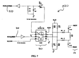
demodulation circuit 520 according to an embodiment of the invention. FIG. 8 is agraph 800 of an amplitude-modulated signal of the type produced by modulation/demodulation circuit 520 according to an embodiment of the invention. FIG. 9 is agraph 900 of an amplitude-modulated signal of the type shown in FIG. 8 riding on a boosted electrical voltage signal according to an embodiment of the invention. FIG. 10 is agraph 1000 showing a recovered signal after being modulated and demodulated according to an embodiment of the invention. - As discussed earlier in connection with FIG. 5, the data signal is routed from
input header 560 tomicroprocessor 565, where the data signal is multiplexed and coded prior to being sent to modulation/demodulation circuit 520. The coded data signal is then transmitted by data UART 567 through data modem 570 to modulation/demodulation circuit 520. As illustrated in FIG. 7, the data signal enters modulation/demodulation circuit 520 on a line 701, and is labeled "data_from_controller." The data line is a single-ended square wave 0 to 5V signal. A logic "1" is indicated by a 5 volt direct current (DC) level and a logic "0" is indicated by a 0 volt DC level. This signal is inverted and applied to pin 3 of atransceiver 710, which in the illustrated embodiment is an RS485 transceiver. Pin 3 oftransceiver 710 is an enable pin. A one megahertz (MHz) signal is applied to the data input oftransceiver 710. Whenever pin 3 oftransceiver 710 is high the one MHz signal is passed throughtransceiver 710 to the differential outputs present on pin 6 andpin 7 oftransceiver 710. The resultant waveform on pin 6 oftransceiver 710 is an amplitude-modulated signal of the type shown in FIG. 8. Since the output oftransceiver 710 is a differential signal, the same signal is present onpin 7 oftransceiver 710, except that the signal onpin 7 oftransceiver 710 is 180 degrees out of phase with the signal on pin 6 oftransceiver 710. - A 110 ohm resistor, R35, loads the differential signals present at
pins 6 and 7 oftransceiver 710. Resisters R32, R33, R37, and R38 bias pins 6 and 7 oftransceiver 710 so that the steady state level ofpin 1 oftransceiver 710 is a logical "0." The signals present atpins 6 and 7 oftransceiver 710 are AC coupled through capacitors C33 and C35 to connector pins 7and 8 ofend 131, which is illustrated as an RJ45 connector in FIG. 7. Resistors R51 and R54 and capacitors C33 and C35 are used to match the differential signal to the impedance of electrical cable 130 (FIGs. 1-4) and to the receiver input impedance. - As illustrated in FIG. 8,
graph 800 comprises achannel 810 and achannel 820.Channel 810 represents data input on line 701 (FIG. 7) of modulation/demodulation circuit 520 (FIGs. 5 and 7).Channel 820 represents an amplitude-modulated signal such as may be present on pin 6 orpin 7 oftransceiver 710. - FIG. 9, in
graph 900, illustrates a modulated data signal of the type produced by modulation/demodulation circuit 520 riding on an electrical power signal having a boosted voltage produced by voltage boost circuit 510 (FIG. 5).Graph 900 comprises achannel 910 and achannel 920.Channel 910 represents data input on line 701 (FIG. 7) of modulation/demodulation circuit 520 (FIGs. 5 and 7).Channel 920 represents modulated data riding on an electrical power signal having a boosted voltage of 30 volts. As described above, the modulated data signal and the boosted electrical voltage signal are simultaneously carried on a single wire pair in electrical cable 130 (FIGs. 1-4). As an example, pins 7 and 8 ofend 131, shown in FIG. 7, correspond to the two wires of the single wire pair on which the combined signal is carried. In a CAT 5 cable, the two wires form a twisted wire pair, as mentioned above. - To demodulate the data signal, the modulated differential signal is received at
pins 6 and 7 oftransceiver 710.Transceiver 710 converts this signal to a single-ended output onpin 1 oftransceiver 710. An example of the type of single-ended output that may be onpin 1 oftransceiver 710 is illustrated in agraph 1000 of FIG. 10. Referring still to FIG. 7, the single-ended output is demodulated using a diode D3, a capacitor C34, and a resistor R34. The signal is inverted and then input to data UART 567 ofmicroprocessor 565. - Referring again to FIG. 10,
graph 1000 comprises achannel 1010 and achannel 1020.Channel 1010 represents a modulated data signal such as may be received onpin 1 oftransceiver 710.Channel 1020 represents a recovered signal present at an output of abuffer 720, which buffer is labeled "Data_Input To_Controller" in FIG. 7. - FIG. 11 is a circuit diagram illustrating a portion of modulation/
demodulation circuit 520 and afilter circuit 530 according to an embodiment of the invention.Filter circuit 530 prevents the one MHz signal (first discussed in connection with FIG. 7) from interfering with power supply 515 and the circuitry ofsubsystem 110. As illustrated in FIG. 11, the data signal is coupled onto the connector pins 7 and 8 ofend 131 through capacitors C33 and C35. The data signal is blocked from the power of power supply 515 and from the ground signals by inductors L4, L2, L3, and L1, and by a capacitor C46. In the embodiment illustrated in FIG. 11, the modulated data signal is riding on the boosted voltage power line, and on the ground line, but is prevented from back-feeding into power supply 515 byfilter circuit 530. As discussed above, filter circuit 630 (FIG. 6) ofsubsystem 120 is the same or substantially similar tofilter circuit 530. Accordingly, the data signal can be transmitted bi-directionally down a single twisted pair of a CAT5 cable or other electrical cable 130 (FIGs. 1-4) and the DC voltage can be delivered tosubsystem 120 on the same twisted pair without interfering with the circuitry ofsubsystem 110 orsubsystem 120. - FIG. 12 is a circuit diagram illustrating
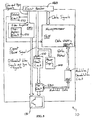
detection circuit 540. A portion 1210 ofdetection circuit 540 is located onsubsystem 110, and aportion 1220 ofdetection circuit 540 is located onsubsystem 120.Subsystem 110 only applies the 5V DC "logic '1'" signal to pin 7 ofend 131 until it is determined thatsubsystem 120 is connected. When it has been determined thatsubsystem 120 unit is connected,subsystem 110 enablesvoltage boost circuit 510 which supplies boosted voltage to pin 7 of end 131 (FIG. 1) which in FIG. 12 is illustrated as an RJ45 connector. The detection mechanism ofdetection circuit 540 comprises a simple circuit to designed to detect that a correct load is attached to the wire pair carrying the combined data and power signal As illustrated in FIG. 12, 5V DC is applied through a diode D1 and a resistor R59 to pin 7 of the RJ45 connector. Withsubsystem 120 connected via electrical cable 130 (FIGs. 1-4), resistors R59 and R62 form a voltage divider to ground. With a transistor Q2 turned on by the "CNTR_5V_32V_SELECT" signal, a transistor Q1 passes the voltage at the node of resistors R59 and R62 to the ADC input pin on microprocessor 665 (FIG. 6) ofsubsystem 120.Microprocessor 665 samples this voltage and, if it is within a predetermined range, transistor Q2 is turned off and the boosted voltage will be applied topin 7 of the RJ45 connector. On the other hand, ifsubsystem 120 is not connected to subsystem 110, or ifsubsystem 110 is connected to a network device, such as a hub, a switch, a router, or the like, the voltage at the node of resistors R59 and R62 will not be in the predetermined acceptable range, and the boosted voltage will not be enabled. - FIG. 13 is a circuit diagram illustrating
pre-emphasis circuit 551, which is designed to emphasize the high frequency component of the video signals, before such signals are transmitted, in anticipation of the high frequency attenuation that occurs over long lengths of electrical cable 130 (FIGs. 1-4). As illustrated in FIG. 13, capacitors C51 and C52 and resistors R69 and R70 are switched into the feedback leg of a differential driver U6 by a transistor Q6. Capacitors C51 and C52 and resistors R69 and R70 give a low impedance feedback path for high frequencies, thus peaking the gain of the high frequency components in the amplifier. A switch onsubsystem 120 ultimately controls transistor Q6. The switch is read bymicroprocessor 665 ofsubsystem 120, and the status of the switch is transmitted back tosubsystem 110 over wire pair carrying the combined data and power signal Capacitors C17 and C27 and resistors R63 and R64 are also used to adjust the amplifier frequency response. - FIG. 14 is a circuit diagram illustrating attenuation/
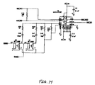
compensation circuit 651. As was first discussed above in connection with FIG. 6,subsystem 120 accepts the differential video signals fromsubsystem 110, amplifies the video signals, and outputs a signal-ended video signal to connector 680 (FIG. 4). As the length of electrical cable 130 (FIGs. 1-4) increases, the higher frequency components of the video signals are increasingly more attenuated during their transmission alongelectrical cable 130, as discussed above. To compensate for the loss of amplitude, a series resistor and capacitor are placed in parallel with a gain resistor R20 of the differential-to-signal-ended amplifier that form a part of video amplifier 650 (FIG. 6). In this way, various compensation legs can be switched into the feedback path. A resistor R61 and a capacitor C48, a resistor R60 and a capacitor C47, and a resistor R59 and a capacitor C46 respectively form the three resistor-capacitor (RC) pairs. - A microprocessor control signal enables or disables one RC pair at a time depending on a user control switch read by
microprocessor 665. These capacitors and resistors give a low impedance feedback path for high frequencies, thus peaking the gain of the high frequency components in the amplifier. The range of frequencies that are peaked and the final gain is dependent on the RC pair that is switched in parallel with gain resistor R20. In this way compensation for attenuation of high frequencies in electrical cable 130 (FIGs. 1-4) is accomplished for varying lengths ofelectrical cable 130. - FIG. 15 is a flow chart illustrating a
method 1500 for increasing a distance between a computer and an operator control center in electrical communication with the computer, where the electrical communication is accomplished via a cable having a first wire pair and a second wire pair. Astep 1510 ofmethod 1500 is to provide a first subsystem to be coupled to a first end of the cable. As an example, the cable can be similar toelectrical cable 130, the computer can be similar todevice 145, and the operator control center can be similar todevice 150, all of which were first shown in FIG. 1. As a further example, the first subsystem can be similar tosubsystem 110, also first shown in FIG. 1. - A
step 1520 ofmethod 1500 is to provide a second subsystem to be coupled to a second end of the cable such that an electrical power signal provided by the computer and a data signal generated by the computer or the operator control center are transmitted simultaneously across the first wire pair between the computer and the operator control center. As an example, the second subsystem can be similar tosubsystem 120, first shown in FIG. 1. - A
step 1530 ofmethod 1500 is to modulate the data signal to create a modulated data signal As an example, the modulated data signal can be similar to the signal shown onchannel 820 in FIG. 8. As an example, the modulated data signal can be created using modulation/demodulation circuit 520, first shown in FIG. 5, or modulation/demodulation circuit 620, first shown in FIG. 6. - A
step 1540 ofmethod 1500 is to modify the electrical power signal to create a boosted electrical voltage signal. As an example, the boosted electrical voltage signal can be created usingvoltage boost circuit 510. - A
step 1550 ofmethod 1500 is to couple the modulated data signal onto the boosted electrical power voltage to create a combined signal As an example, the combined signal can be similar to the signal shown onchannel 920 in FIG. 9. - A
step 1560 ofmethod 1500 is to transmit the combined signal across the first wire pair between the computer and the operator control center. In one embodiment,step 1530 or another step can further comprise using the computer to generate a video signal, and step 1560 or another step can further comprise transmitting the video signal across the second wire pair between the computer and the operator control center. In the same or another embodiment,step 1560 or another step further comprises demodulating the modulated data signal after transmitting the modulated data signal across the first wire pair, and/or reducing the boosted electrical voltage signal after transmitting the boosted electrical voltage signal across the first wire pair. In the same or another embodiment,step 1560 or another step further comprises compensating for attenuation of the video signal before transmitting the video signal across the second wire pair and /or compensating for attenuation of the video signal after transmitting the video signal across the second wire pair. In the same or another embodiment,step 1560 or another step further comprises filtering the combined signal to prevent the modulated data signal from interfering with the boosted electrical voltage signal. In the same or another embodiment,step 1560 or another step further comprises detecting the presence of the second subsystem at the first subsystem before enabling the electrical power signal. - In the same or another embodiment of
method 1500,step 1510 or another step further comprises providing a switch and electrically coupling the switch between the computer and the operator control center. As an example, the switch can be similar to switch 240, first shown in FIG. 2. In an embodiment where the distance extender comprises a switch,step 1510 or another step further comprises: (1) electrically coupling the switch between the computer and the first subsystem; and (2) electrically coupling the second subsystem between the first subsystem and the operator control center. In another embodiment,step 1510 or another step further comprises: (1) electrically coupling the switch between the second subsystem and the operator control center; and (2) electrically coupling the first subsystem between the computer and the second subsystem. In another embodiment,step 1510 or another step further comprises: (1) providing a third subsystem substantially similar to the first subsystem; (2) providing a fourth subsystem substantially similar to the second subsystem; (3) electrically coupling the third subsystem between the switch and the fourth subsystem; (4) electrically coupling the fourth subsystem between the third subsystem and the operator control center; and (5) electrically coupling the switch between the second subsystem and the third subsystem. - Although the invention has been described with reference to specific embodiments, it will be understood by those skilled in the art that various changes may be made without departing from the spirit or scope of the invention Various examples of such changes have been given in the foregoing description Accordingly, the disclosure of embodiments of the invention is intended to be illustrative of the scope of the invention and is not intended to be limiting. It is intended that the scope of the invention shall be limited only to the extent required by the appended claims. For example, to one of ordinary skill in the art, it will be readily apparent that the distance extender discussed herein may be implemented in a variety of embodiments, and that the foregoing discussion of certain of these embodiments does not necessarily represent a complete description of all possible embodiments.
- All elements claimed in any particular claim are essential to the invention claimed in that particular claim. Consequently, replacement of one or more claimed elements constitutes reconstruction and not repair. Additionally, benefits, other advantages, and solutions to problems have been described with regard to specific embodiments. The benefits, advantages, solutions to problems, and any element or elements that may cause any benefit, advantage, or solution to occur or become more pronounced, however, are not to be construed as critical, required, or essential features or elements of any or all of the claims.
- Moreover, embodiments and limitations disclosed herein are not dedicated to the public under the doctrine of dedication if the embodiments and/or limitations: (1) are not expressly claimed in the claims; and (2) are or are potentially equivalents of express elements and/or limitations in the claims under the doctrine of equivalents.
Claims (33)
- A distance extender for increasing a distance between a first device and a second device in electrical communication with the first device, the distance extender comprising:wherein:an electrical cable electrically coupled between the first device and the second device and comprising:a first end;a second end; anda plurality of wires extending between the first end and the second end;a first subsystem electrically coupled to the first end of the electrical cable and to the first device; anda second subsystem electrically coupled to the second end of the electrical cable and the second device,the first device or the second device generates a data signal and the first device provides an electrical power signal;the plurality of wires includes a first wire; andthe data signal and the electrical power signal are simultaneously transmitted between the first device and the second device over the first wire.
- The distance extender of claim 1 wherein:the data signal comprises at least one of mouse data and keyboard data and is transmitted from the first device to the second device and from the second device to the first device.
- The distance extender of claim 1 or claim 2 wherein:the first wire forms a portion of a first wire pair; andthe data signal and the electrical power signal are simultaneously transmitted between the first device and the second device over the first wire pair.
- The distance extender of any of claims 1 to 3 further comprising:a switch electrically coupled between the first device and the second device.
- The distance extender of claim 4 wherein:the switch is a keyboard, video, and mouse switch.
- The distance extender of claim 4 or claim 5 wherein:the switch is electrically coupled between the first device and the first subsystem
- The distance extender of claim 4 or claim 5 wherein:the switch is electrically coupled between second subsystem and the second device.
- The distance extender of claim 4 or claim 5 further comprising:wherein:a third subsystem substantially similar to the first subsystem; anda fourth subsystem substantially similar to the second subsystem,the third subsystem is electrically coupled between the switch and the fourth subsystem;the fourth subsystem is electrically coupled between the third subsystem and the second device; andthe switch is electrically coupled between the second subsystem and the third subsystem.
- The distance extender of any preceding claim wherein:the electrical cable comprises four unshielded twisted wire pairs; andthe first wire is a portion of one of the four unshielded twisted wire pairs.
- The distance extender of any preceding claim wherein:power to operate at least a portion of the second device is provided only by the electrical power signal.
- The distance extender of any preceding claim wherein:the second subsystem comprises:a voltage conversion circuit; andan attenuation compensation circuit.
- A distance extender for increasing a distance between a computer and an operator control center in electrical communication with the computer, the distance extender comprising:wherein:a Category 5-type cable comprising:a first end;a second end; anda plurality of wires extending between the first end and the second end, the plurality of wires comprising:a first twisted pair;a second twisted pair;a third twisted pair; anda fourth twisted pair;a first subsystem electrically coupled between the first end of the Category 5-type cable and the computer; anda second subsystem electrically coupled between the second end of the Category 5-type cable and the operator control center,the operator control center comprises:a computer keyboard;a computer video monitor; anda computer mouse;the computer provides an electrical power signal and the computer or the operator control center generates a data signal and a plurality of video signals;the plurality of video signals are transmitted between the first subsystem and the second subsystem over the first, second, and third twisted pairs; andthe data signal and the electrical power signal are simultaneously transmitted between the first subsystem and the second subsystem over the fourth twisted pair.
- The distance extender of claim 12 wherein:the first subsystem, the second subsystem, the computer keyboard, and the computer mouse are powered only by the electrical power signal.
- The distance extender of any preceding claim wherein:the first subsystem comprises:a voltage boost circuita modulation/demodulation circuit;a filter circuit;a detection circuit; anda pre-emphasis circuit.
- The distance extender of any preceding claim wherein:the second subsystem comprises:a voltage conversion circuit;a modulation/demodulation circuit;a filter circuit; andan attenuation compensation circuit.
- The distance extender of claim 15 when dependent on claim 14 wherein:the pre-emphasis circuit increases a high-frequency portion of the plurality of video signals before the plurality of video signals are transmitted across the first, second, and third twisted pairs; andthe attenuation compensation circuit compensates for a loss of amplitude in the plurality of video signals after the plurality of video signals are transmitted across the first, second, and third twisted pairs.
- The distance extender of claim 14 or claim 16 wherein:the first subsystem receives the electrical power signal from the computer; andthe voltage boost circuit boosts the electrical voltage signal before passing the electrical power signal to the Category 5-type cable.
- The distance extender of any of claims 12 to 17 further comprising:a keyboard, video, and mouse switch electrically coupled between the computer and the operator control center.
- The distance extender of claim 18 wherein:the keyboard, video, and mouse switch is electrically coupled between the first subsystem and the computer.
- The distance extender of claim 18 wherein:the keyboard, video, and mouse switch is electrically coupled between the second subsystem and the operator control center.
- The distance extender of claim 18 further comprising:wherein:a third subsystem substantially similar to the first subsystem; anda fourth subsystem substantially similar to the second subsystem,the third subsystem is electrically coupled between the keyboard, video, and mouse switch and the fourth subsystem;the fourth subsystem is electrically coupled between the third subsystem and the operator control center; andthe keyboard, video, and mouse switch is electrically coupled between the second subsystem and the third subsystem.
- A method for increasing a distance between a computer and an operator control center in electrical communication with the computer where the electrical communication is accomplished via a cable having a first wire pair and a second wire pair, the method comprising:providing a first subsystem to be coupled to a first end of the cable;providing a second subsystem to be coupled to a second end of the cable such that an electrical power signal provided by the computer and a data signal generated by the computer or the operator control center are transmitted simultaneously across the first wire pair between the computer and the operator control center.
- The method of claim 22 further comprising:providing a switch; andelectrically coupling the switch between the computer and the operator control center.
- The method of claim 23 further comprising:electrically coupling the switch between the computer and the first subsystem; andelectrically coupling the second subsystem between the first subsystem and the operator control center.
- The method of claim 23 further comprising:electrically coupling the switch between the second subsystem and the operator control center; andelectrically coupling the first subsystem between the computer and the second subsystem.
- The method of claim 23 further comprising:providing a third subsystem substantially similar to the first subsystem; providing a fourth subsystem substantially similar to the second subsystem,electrically coupling the third subsystem between the switch and the fourth subsystem;electrically coupling the fourth subsystem between the third subsystem and the operator control center, andelectrically coupling the switch between the second subsystem and the third subsystem.
- The method of any of claims 22 to 26 further comprising:modulating the data signal to create a modulated data signal;modifying the electrical power signal to create a boosted electrical voltage signal;coupling the modulated data signal onto the electrical power signal to create a combined signal; andtransmitting the combined signal across the first wire pair between the computer and the operator control center.
- The method of claim 27 further comprising:using the computer to generate a video signal; andtransmitting the video signal across the second wire pair between the computer and the operator control center.
- The method of claim 28 further comprising:demodulating the modulated data signal after transmitting the modulated data signal across the first wire pair; andreducing the boosted electrical voltage signal after transmitting the boosted electrical voltage signal across the first wire pair.
- The method of claim 28 or claim 29 further comprising:compensating for attenuation of the video signal before transmitting the video signal across the second wire pair.
- The method of any of claims 28 to 30 further comprising:compensating for attenuation of the video signal after transmitting the video signal across the second wire pair.
- The method of any of claims 27 to 31 further comprising:filtering the combined signal to prevent the modulated data signal from interfering with the boosted electrical voltage signal.
- The method of any of claims 22 to 32 further comprising:detecting the presence of the second subsystem at the first subsystem before enabling the electrical power signal.
Applications Claiming Priority (2)
| Application Number | Priority Date | Filing Date | Title |
|---|---|---|---|
| US10/670,403 US7259482B2 (en) | 2003-09-24 | 2003-09-24 | Distance extender and method making use of same |
| US670403 | 2003-09-24 |
Publications (3)
| Publication Number | Publication Date |
|---|---|
| EP1519495A2 true EP1519495A2 (en) | 2005-03-30 |
| EP1519495A3 EP1519495A3 (en) | 2006-08-16 |
| EP1519495B1 EP1519495B1 (en) | 2010-11-03 |
Family
ID=34194822
Family Applications (1)
| Application Number | Title | Priority Date | Filing Date |
|---|---|---|---|
| EP04255820A Not-in-force EP1519495B1 (en) | 2003-09-24 | 2004-09-24 | Cable distance extender and method making use of same |
Country Status (8)
| Country | Link |
|---|---|
| US (2) | US7259482B2 (en) |
| EP (1) | EP1519495B1 (en) |
| AT (1) | ATE487285T1 (en) |
| AU (1) | AU2004214549B2 (en) |
| CA (1) | CA2482208C (en) |
| DE (1) | DE602004029854D1 (en) |
| ES (1) | ES2355622T3 (en) |
| NZ (1) | NZ535506A (en) |
Cited By (2)
| Publication number | Priority date | Publication date | Assignee | Title |
|---|---|---|---|---|
| EP2081301A1 (en) * | 2008-01-15 | 2009-07-22 | E-Media Solutions (EMS) B.V. | Computer power line communication adaptor and device line communication adaptor |
| DE102007029828B4 (en) * | 2007-06-28 | 2017-03-16 | Eizo Gmbh | Arrangement with an image source and a picture reproducing system |
Families Citing this family (35)
| Publication number | Priority date | Publication date | Assignee | Title |
|---|---|---|---|---|
| US6480510B1 (en) | 1998-07-28 | 2002-11-12 | Serconet Ltd. | Local area network of serial intelligent cells |
| US6956826B1 (en) * | 1999-07-07 | 2005-10-18 | Serconet Ltd. | Local area network for distributing data communication, sensing and control signals |
| US6549616B1 (en) | 2000-03-20 | 2003-04-15 | Serconet Ltd. | Telephone outlet for implementing a local area network over telephone lines and a local area network using such outlets |
| US6961303B1 (en) * | 2000-09-21 | 2005-11-01 | Serconet Ltd. | Telephone communication system and method over local area network wiring |
| IL152824A (en) * | 2002-11-13 | 2012-05-31 | Mosaid Technologies Inc | Addressable outlet and a network using same |
| IL159838A0 (en) | 2004-01-13 | 2004-06-20 | Yehuda Binder | Information device |
| US7415552B2 (en) * | 2004-04-15 | 2008-08-19 | Aten International Co., Ltd | Keyboard video mouse switch for multiple chaining and the method thereof |
| US7613854B2 (en) | 2004-04-15 | 2009-11-03 | Aten International Co., Ltd | Keyboard video mouse (KVM) switch wherein peripherals having source communication protocol are routed via KVM switch and converted to destination communication protocol |
| US8407347B2 (en) * | 2004-11-19 | 2013-03-26 | Xiao Qian Zhang | Method of operating multiple input and output devices through a single computer |
| TWM300839U (en) * | 2006-02-24 | 2006-11-11 | June On Co Ltd | Assembling framework of bi-directional adjustable computer switch |
| US8120583B2 (en) * | 2006-09-08 | 2012-02-21 | Aten International Co., Ltd. | KVM switch capable of detecting keyword input and method thereof |
| US9286026B2 (en) | 2006-09-08 | 2016-03-15 | Aten International Co., Ltd. | System and method for recording and monitoring user interactions with a server |
| US20080136385A1 (en) * | 2006-12-08 | 2008-06-12 | Aten International Co., Ltd. | Power transmission system |
| US20090043928A1 (en) * | 2007-08-08 | 2009-02-12 | Tony Lou | Interface device and master device of a kvm switch system and a related method thereof |
| US20090125654A1 (en) * | 2007-11-12 | 2009-05-14 | Tony Lou | KVM Switch |
| US8024502B2 (en) * | 2008-04-18 | 2011-09-20 | Aten International Co., Ltd. | KVM extender system and local, remote modules thereof |
| WO2009133890A1 (en) * | 2008-04-28 | 2009-11-05 | 日本電気株式会社 | Compound switch and portable apparatus with the same |
| US8249501B2 (en) * | 2008-05-05 | 2012-08-21 | International Business Machines Corporation | Self-detecting electronic connection for electronic devices |
| JP5318704B2 (en) * | 2009-08-20 | 2013-10-16 | 富士通コンポーネント株式会社 | Signal transmission system |
| US8159085B2 (en) | 2009-09-25 | 2012-04-17 | Pucline, Llc | Wall-mountable electrical power supplying device having a ring-like structure for receiving the power plugs and/or power adapters associated with a plurality of electrical appliances, and a housing containing and concealing the same during power supply operations |
| US9184546B2 (en) | 2009-09-25 | 2015-11-10 | Pucline, Llc | Electrical power supplying device having a central power-hub assembly supplying electrical power to power plugs, adaptors and modules while concealed from view and managing excess power cord during power supplying operations |
| US8002587B2 (en) | 2009-09-25 | 2011-08-23 | Pucline, Llc | Ring-like electical power supplying structure for receiving the electrical power plugs of a plurality of electrical appliances and powering the same |
| US8193658B2 (en) | 2009-09-25 | 2012-06-05 | Pucline, Llc | Electrical power supplying device having a ring-like subassembly for receiving the power plugs and/or power adapters associated with a plurality of electrical appliances, and managing excess power cord length therewithin in a concealed manner |
| US8016611B2 (en) | 2009-09-25 | 2011-09-13 | Pucline Llc | Electrical power supplying device having a ring-like structure for receiving the power plugs and/or power adapters associated with a plurality of electrical appliances, and an integrated thermal management system |
| US8217528B2 (en) | 2009-09-25 | 2012-07-10 | PUCline, Inc. | Electrical power supplying device having a ring-like subassembly for receiving the power plugs and/or power adapters associated with a plurality of electrical appliances, and a housing design for containing and concealing the power plug and adaptors during power supplying operations |
| US20140035363A1 (en) | 2009-09-25 | 2014-02-06 | Pucline, Llc | Electrical power supplying device having a central power-receptacle assembly supplying electrical power to power plugs, adaptors and modules while concealed from view and managing excess power cord during power supplying operations |
| US8174147B2 (en) | 2009-09-25 | 2012-05-08 | Pucline, Llc | Electrical power supplying device having a ring-like power assembly for receiving electrical power plugs and/or power adapters associated with a plurality of electrical appliances, and an un-interrupted power supply (UPS) unit having a battery componenent mounted within a centrally-disposed structure passing through a central aperture in said ring-like power assembly |
| US8002586B2 (en) | 2009-09-25 | 2011-08-23 | Pucline, Llc | Electrical power supplying device having a lower deck housing region for containing and concealing a plurality of electrical power adapters associated with a plurality of electrical appliances, and an upper deck housing region for supporting a ring-like power assembly having a central aperture and receiving the power plugs and/or power adapters of electrical appliances, while managing excess power cord length within a 3D volume passing through said central aperture |
| US8026633B2 (en) | 2009-09-25 | 2011-09-27 | Pucline, Llc | Wall-mountable electrical power supplying device for mounting to a wall surface about a standard wall-mounted power receptacle, using a mounting bracket arranged between the housing and wall surface and an electrical power supply plug integrated with the housing |
| KR101116483B1 (en) * | 2009-12-04 | 2012-02-27 | 삼성에스디아이 주식회사 | Energy Storage System |
| US20110208963A1 (en) | 2010-02-24 | 2011-08-25 | Aviv Soffer | Secured kvm system having remote controller-indicator |
| US20120331194A1 (en) * | 2011-06-23 | 2012-12-27 | Apple Inc. | Interface extender for portable electronic devices |
| US9927837B2 (en) | 2013-07-03 | 2018-03-27 | Pucline, Llc | Electrical power supplying system having an electrical power supplying docking station with a multi-function module for use in diverse environments |
| US9513682B2 (en) | 2013-07-03 | 2016-12-06 | Pucline, Llc | Transportable electrical power supplying device for storing and configuring excess power cord and sharing a multiplicity of AC and DC electrical power supplies in diverse user environments |
| CN105515927A (en) * | 2015-11-27 | 2016-04-20 | 武汉微创光电股份有限公司 | Remote serial port communication system and method based on Ethernet Cat.5 wiring framework |
Family Cites Families (158)
| Publication number | Priority date | Publication date | Assignee | Title |
|---|---|---|---|---|
| US38334A (en) * | 1863-04-28 | Improvement in direct-action steam-pumps | ||
| US54029A (en) * | 1866-04-17 | Improvement in gang-plows | ||
| US53711A (en) * | 1866-04-03 | Improvement in the construction of pulleys | ||
| US5186A (en) * | 1847-07-10 | Ship s block | ||
| US35049A (en) * | 1862-04-22 | Improved slide for harness | ||
| US5742677A (en) * | 1995-04-03 | 1998-04-21 | Scientific-Atlanta, Inc. | Information terminal having reconfigurable memory |
| US3634830A (en) | 1969-06-13 | 1972-01-11 | Ibm | Modular computer sharing system with intercomputer communication control apparatus |
| US6452482B1 (en) * | 1999-12-30 | 2002-09-17 | Ambient Corporation | Inductive coupling of a data signal to a power transmission cable |
| US3955188A (en) | 1971-01-04 | 1976-05-04 | Honeywell Information Systems Inc. | Encoding technique for enabling a device to process different types of digital information transmitted along a single information channel |
| US3774158A (en) | 1972-01-06 | 1973-11-20 | Rca Corp | Multiple terminal display system |
| US4081797A (en) | 1972-11-03 | 1978-03-28 | Heath Company | On-screen channel display |
| US4150429A (en) | 1974-09-23 | 1979-04-17 | Atex, Incorporated | Text editing and display system having a multiplexer circuit interconnecting plural visual displays |
| US4078249A (en) | 1976-06-01 | 1978-03-07 | Raytheon Company | Digital display composition system |
| US4243984A (en) | 1979-03-08 | 1981-01-06 | Texas Instruments Incorporated | Video display processor |
| US4313176A (en) | 1980-03-07 | 1982-01-26 | The Lockwood Association, Inc. | Data controlled switch for telephone inputs to a computer |
| US4461262A (en) * | 1981-01-16 | 1984-07-24 | Edward Chow | Fuel treating device |
| US4468612A (en) | 1982-01-15 | 1984-08-28 | At&T Bell Laboratories | Arrangement for indicating when different types of electrical components are interconnected |
| US4479122A (en) | 1982-03-05 | 1984-10-23 | At&T Bell Laboratories | Remotely controlled switched access to the console port of an electronic computer |
| US4599611A (en) | 1982-06-02 | 1986-07-08 | Digital Equipment Corporation | Interactive computer-based information display system |
| JPS59114631A (en) | 1982-12-22 | 1984-07-02 | Hitachi Ltd | Terminal control device |
| US4641262A (en) | 1983-03-07 | 1987-02-03 | International Business Machines Corporation | Personal computer attachment for host system display station |
| US4665501A (en) | 1983-09-30 | 1987-05-12 | Esprit Systems, Inc. | Workstation for local and remote data processing |
| US4823256A (en) | 1984-06-22 | 1989-04-18 | American Telephone And Telegraph Company, At&T Bell Laboratories | Reconfigurable dual processor system |
| US4630284A (en) | 1984-12-28 | 1986-12-16 | Gte Laboratories Incorporated | Low power line driving digital transmission system |
| US4680622A (en) | 1985-02-11 | 1987-07-14 | Ncr Corporation | Apparatus and method for mixing video signals for simultaneous presentation |
| US4710917A (en) | 1985-04-08 | 1987-12-01 | Datapoint Corporation | Video conferencing network |
| US4730251A (en) | 1985-10-28 | 1988-03-08 | International Business Machines Corporation | Automatic I/O address assignment |
| US4939507A (en) | 1986-04-28 | 1990-07-03 | Xerox Corporation | Virtual and emulated objects for use in the user interface of a display screen of a display processor |
| US4807184A (en) | 1986-08-11 | 1989-02-21 | Ltv Aerospace | Modular multiple processor architecture using distributed cross-point switch |
| SE454730B (en) | 1986-09-19 | 1988-05-24 | Asea Ab | PROCEDURE AND COMPUTER EQUIPMENT FOR SHORT-FREE REPLACEMENT OF THE ACTIVITY FROM ACTIVE DEVICES TO EMERGENCY UNITS IN A CENTRAL UNIT |
| US5230066A (en) | 1986-09-19 | 1993-07-20 | Mitsubishi Denki Kabushiki Kaisha | Microcomputer |
| US4768083A (en) | 1987-04-29 | 1988-08-30 | Rca Licensing Corporation | Digital TV having on-screen display feature |
| US5029111A (en) | 1987-04-29 | 1991-07-02 | Prime Computer, Inc. | Shared bit-plane display system |
| US4972470A (en) | 1987-08-06 | 1990-11-20 | Steven Farago | Programmable connector |
| US5268676A (en) | 1987-09-11 | 1993-12-07 | Cybex Corporation | Computer-monitor extended range communications link |
| US5465105A (en) | 1987-09-11 | 1995-11-07 | Cybex Corporation | Autosensing switching system |
| US4907079A (en) | 1987-09-28 | 1990-03-06 | Teleview Rating Corporation, Inc. | System for monitoring and control of home entertainment electronic devices |
| US5121486A (en) | 1987-11-20 | 1992-06-09 | Hitachi, Ltd | Network control system for dynamically switching a logical connection between an identified terminal device and an indicated processing unit |
| US4879716A (en) | 1987-12-23 | 1989-11-07 | Bull Hn Information Systems Inc. | Resilient data communications system |
| US4800429A (en) | 1988-03-14 | 1989-01-24 | Motorola, Inc. | Auto sync polarity control circuit for use with monitor |
| US5043866A (en) | 1988-04-08 | 1991-08-27 | International Business Machines Corporation | Soft checkpointing system using log sequence numbers derived from stored data pages and log records for database recovery |
| US5280583A (en) | 1988-05-13 | 1994-01-18 | Hitachi, Ltd. | System and method for performing interlocution at a plurality of terminals connected to communication network |
| US4949248A (en) | 1988-07-15 | 1990-08-14 | Caro Marshall A | System for shared remote access of multiple application programs executing in one or more computers |
| US5226123A (en) | 1988-07-27 | 1993-07-06 | Peter Vockenhuber | System for addressing multiple addressable units by inactivating previous units and automatically change the impedance of the connecting cable |
| US5222212A (en) | 1988-09-16 | 1993-06-22 | Chips And Technologies, Inc. | Fakeout method and circuitry for displays |
| JPH0290335A (en) | 1988-09-28 | 1990-03-29 | Hitachi Ltd | Remote operation control system for computer system |
| US5036484A (en) | 1988-11-23 | 1991-07-30 | International Business Machines Corporation | Personal computer/host emulation system for handling host data with personal computer application programs at personal computers |
| US4876712A (en) | 1988-12-09 | 1989-10-24 | Electronics, Inc. | Programmable telephone amplifier circuit interface |
| US4953159A (en) | 1989-01-03 | 1990-08-28 | American Telephone And Telegraph Company | Audiographics conferencing arrangement |
| US4953027A (en) | 1989-04-24 | 1990-08-28 | Motorola Inc. | OSD in a TV receiver including a window, smoothing and edge enhancing |
| US5117225A (en) | 1989-05-01 | 1992-05-26 | Summit Micro Design | Computer display screen monitoring system |
| US5369593A (en) | 1989-05-31 | 1994-11-29 | Synopsys Inc. | System for and method of connecting a hardware modeling element to a hardware modeling system |
| US5214785A (en) | 1989-09-27 | 1993-05-25 | Third Point Systems, Inc. | Controller with keyboard emulation capability for control of host computer operation |
| US5099319A (en) | 1989-10-23 | 1992-03-24 | Esch Arthur G | Video information delivery method and apparatus |
| US4949169A (en) | 1989-10-27 | 1990-08-14 | International Business Machines Corporation | Audio-video data interface for a high speed communication link in a video-graphics display window environment |
| JPH03160494A (en) | 1989-11-10 | 1991-07-10 | Internatl Business Mach Corp <Ibm> | Datacprocessing device |
| US5051720A (en) | 1989-11-13 | 1991-09-24 | Secure Telecom, Inc. | Remote control system using power line of remote site |
| US5128766A (en) | 1989-11-30 | 1992-07-07 | Goldstar Co., Ltd. | Multiple television receiver with teletext function |
| US5333286A (en) | 1989-12-13 | 1994-07-26 | Joseph Weinberger | Two way copier monitoring system |
| JP2793308B2 (en) | 1989-12-21 | 1998-09-03 | 株式会社日立製作所 | Dialogue system |
| US5161156A (en) | 1990-02-02 | 1992-11-03 | International Business Machines Corporation | Multiprocessing packet switching connection system having provision for error correction and recovery |
| JP3092135B2 (en) | 1990-03-13 | 2000-09-25 | 株式会社日立製作所 | Application execution control method |
| US5396635A (en) * | 1990-06-01 | 1995-03-07 | Vadem Corporation | Power conservation apparatus having multiple power reduction levels dependent upon the activity of the computer system |
| US5260778A (en) | 1990-06-26 | 1993-11-09 | General Instrument Corporation | Apparatus for selective distribution of messages over a communications network |
| US5220380A (en) | 1990-08-10 | 1993-06-15 | Minolta Camera Kabushiki Kaisha | Control system for copying machines with improved communication function for centralized control unit |
| US5349675A (en) | 1990-09-04 | 1994-09-20 | International Business Machines Corporation | System for directly displaying remote screen information and providing simulated keyboard input by exchanging high level commands |
| JPH04357521A (en) * | 1990-10-10 | 1992-12-10 | Fuji Xerox Co Ltd | Information processor |
| US5327156A (en) | 1990-11-09 | 1994-07-05 | Fuji Photo Film Co., Ltd. | Apparatus for processing signals representative of a computer graphics image and a real image including storing processed signals back into internal memory |
| US5261079A (en) | 1990-12-18 | 1993-11-09 | International Business Machines Corporation | Interface for keyboard emulation provided by an operating system |
| US5617547A (en) * | 1991-03-29 | 1997-04-01 | International Business Machines Corporation | Switch network extension of bus architecture |
| JPH0546568A (en) | 1991-08-08 | 1993-02-26 | Internatl Business Mach Corp <Ibm> | Dispersion application execution device and method |
| US5181858A (en) | 1991-08-30 | 1993-01-26 | Amp Incorporated | Cable type identifying and impedance matching arrangement |
| EP0532102B1 (en) | 1991-09-11 | 1998-04-22 | Lucent Technologies Inc. | System for controlling data access to a data apparatus |
| JPH0589069A (en) | 1991-09-30 | 1993-04-09 | Toshiba Corp | Dispersion type control system |
| FR2682786B1 (en) | 1991-10-17 | 1993-12-10 | Bull Sa | DOWNLOADING AN OPERATING SYSTEM THROUGH A NETWORK. |
| US5734334A (en) * | 1991-10-30 | 1998-03-31 | I-Cube, Inc. | Programmable port for crossbar switch |
| US5287461A (en) | 1991-10-31 | 1994-02-15 | Sun Microsystems, Inc. | Method and apparatus for remotely accessing a plurality of server consoles |
| US5330370A (en) | 1991-11-04 | 1994-07-19 | Spectra-Physics Scanning Systems, Inc. | Multiple-interface selection system for computer peripherals |
| US5347113A (en) | 1991-11-04 | 1994-09-13 | Spectra-Physics Scanning Systems, Inc. | Multiple-interface selection system for computer peripherals |
| US5317391A (en) | 1991-11-29 | 1994-05-31 | Scientific-Atlanta, Inc. | Method and apparatus for providing message information to subscribers in a cable television system |
| US5247364A (en) | 1991-11-29 | 1993-09-21 | Scientific-Atlanta, Inc. | Method and apparatus for tuning data channels in a subscription television system having in-band data transmissions |
| US5301028A (en) | 1991-11-29 | 1994-04-05 | Scientific-Atlanta, Inc. | Method and apparatus for displaying channel identification information |
| US5477262A (en) | 1991-11-29 | 1995-12-19 | Scientific-Altanta, Inc. | Method and apparatus for providing an on-screen user interface for a subscription television terminal |
| US5486869A (en) | 1992-02-18 | 1996-01-23 | Cooper; J. Carl | Synchronizing signal separating apparatus and method |
| US5526024A (en) | 1992-03-12 | 1996-06-11 | At&T Corp. | Apparatus for synchronization and display of plurality of digital video data streams |
| US5317695A (en) | 1992-04-03 | 1994-05-31 | International Business Machines Corporation | Method and system for permitting communication between a data processing system and input pointing devices of multiple types |
| US5392400A (en) | 1992-07-02 | 1995-02-21 | International Business Machines Corporation | Collaborative computing system using pseudo server process to allow input from different server processes individually and sequence number map for maintaining received data sequence |
| US5732212A (en) * | 1992-10-23 | 1998-03-24 | Fox Network Systems, Inc. | System and method for remote monitoring and operation of personal computers |
| US5367571A (en) | 1992-12-02 | 1994-11-22 | Scientific-Atlanta, Inc. | Subscriber terminal with plug in expansion card |
| US5357276A (en) | 1992-12-01 | 1994-10-18 | Scientific-Atlanta, Inc. | Method of providing video on demand with VCR like functions |
| US5592551A (en) | 1992-12-01 | 1997-01-07 | Scientific-Atlanta, Inc. | Method and apparatus for providing interactive electronic programming guide |
| US5715515A (en) * | 1992-12-02 | 1998-02-03 | Scientific-Atlanta, Inc. | Method and apparatus for downloading on-screen graphics and captions to a television terminal |
| US5440632A (en) | 1992-12-02 | 1995-08-08 | Scientific-Atlanta, Inc. | Reprogrammable subscriber terminal |
| US5381477A (en) | 1993-02-16 | 1995-01-10 | Scientific-Atlanta, Inc. | Method of selecting cable television converter groups |
| JPH08509849A (en) * | 1993-02-16 | 1996-10-15 | サイエンティフィック−アトランタ・インコーポレーテッド | System and method for remote selection of subscribers and control of messages to subscribers in a cable television system |
| US5608872A (en) | 1993-03-19 | 1997-03-04 | Ncr Corporation | System for allowing all remote computers to perform annotation on an image and replicating the annotated image on the respective displays of other comuters |
| US5499377A (en) | 1993-05-03 | 1996-03-12 | Designed Enclosures, Inc. | Multi-computer access switching system |
| EP0658048B1 (en) * | 1993-05-28 | 2004-01-14 | Sony Corporation | Method for connecting av equipment to av system |
| JPH08511390A (en) | 1993-06-07 | 1996-11-26 | サイエンティフィック−アトランタ・インコーポレーテッド | Display system for subscriber terminals |
| US5485221A (en) | 1993-06-07 | 1996-01-16 | Scientific-Atlanta, Inc. | Subscription television system and terminal for enabling simultaneous display of multiple services |
| JPH0746579A (en) | 1993-07-21 | 1995-02-14 | Sony Corp | Signal monitoring device |
| US5448697A (en) | 1993-09-10 | 1995-09-05 | Dell Usa, L.P. | Method and apparatus for simplified control of a video monitor |
| US5583562A (en) | 1993-12-03 | 1996-12-10 | Scientific-Atlanta, Inc. | System and method for transmitting a plurality of digital services including imaging services |
| US5606604A (en) | 1993-12-13 | 1997-02-25 | Lucent Technologies Inc. | System and method for preventing fraud upon PBX through a remote maintenance or administration port |
| GB9400101D0 (en) * | 1994-01-05 | 1994-03-02 | Thomson Consumer Electronics | Consumer interface for a satellite television system |
| US5583993A (en) | 1994-01-31 | 1996-12-10 | Apple Computer, Inc. | Method and apparatus for synchronously sharing data among computer |
| GB2287106A (en) * | 1994-02-16 | 1995-09-06 | Ibm | Connection of adaptors for multiple bus architectures |
| US5539822A (en) | 1994-04-19 | 1996-07-23 | Scientific-Atlanta, Inc. | System and method for subscriber interactivity in a television system |
| US5768568A (en) * | 1994-04-29 | 1998-06-16 | International Business Machines Corp. | System and method for initializing an information processing system |
| US5524362A (en) | 1994-06-03 | 1996-06-11 | Speed Queen Company | Apparatus and method of using wire harness to select controller mode |
| US5489947A (en) | 1994-06-17 | 1996-02-06 | Thomson Consumer Electronics, Inc. | On screen display arrangement for a digital video signal processing system |
| US5534942A (en) | 1994-06-17 | 1996-07-09 | Thomson Consumer Electronics, Inc. | On screen display arrangement for digital video signal processing system |
| JP3534331B2 (en) | 1994-08-09 | 2004-06-07 | ゼロックス コーポレイション | How to build multi-segment print jobs from a variety of local and remote sources using a network interface |
| US5613096A (en) | 1994-11-04 | 1997-03-18 | Canon Information Systems, Inc. | Network protocol sensor |
| US5542053A (en) | 1994-11-30 | 1996-07-30 | International Business Machines Corporation | Bridge interface between two buses of a computer system with a direct memory access controller programmed by a scatter/gather programmer |
| US5774859A (en) * | 1995-01-03 | 1998-06-30 | Scientific-Atlanta, Inc. | Information system having a speech interface |
| US5581303A (en) | 1995-01-18 | 1996-12-03 | Radius Inc. | Video timing signal generation circuit |
| US5604509A (en) | 1995-04-14 | 1997-02-18 | Advent Design, Inc. | Remote display monitor system |
| US5708961A (en) * | 1995-05-01 | 1998-01-13 | Bell Atlantic Network Services, Inc. | Wireless on-premises video distribution using digital multiplexing |
| US5486868A (en) | 1995-05-19 | 1996-01-23 | Winbond Electronics Corporation | Generator for scan timing of multiple industrial standards |
| US5721842A (en) * | 1995-08-25 | 1998-02-24 | Apex Pc Solutions, Inc. | Interconnection system for viewing and controlling remotely connected computers with on-screen video overlay for controlling of the interconnection switch |
| US5752032A (en) * | 1995-11-21 | 1998-05-12 | Diamond Multimedia Systems, Inc. | Adaptive device driver using controller hardware sub-element identifier |
| US5724529A (en) * | 1995-11-22 | 1998-03-03 | Cirrus Logic, Inc. | Computer system with multiple PC card controllers and a method of controlling I/O transfers in the system |
| US5719622A (en) * | 1996-02-23 | 1998-02-17 | The Regents Of The University Of Michigan | Visual control selection of remote mechanisms |
| US5864708A (en) * | 1996-05-20 | 1999-01-26 | Croft; Daniel I. | Docking station for docking a portable computer with a wireless interface |
| US5758099A (en) * | 1996-05-29 | 1998-05-26 | International Business Machines Corporation | Plug and play protocol for bus adapter card |
| SE510366C2 (en) * | 1996-08-22 | 1999-05-17 | Ericsson Telefon Ab L M | AC / DC Converters |
| US5761448A (en) * | 1996-08-30 | 1998-06-02 | Ncr Corporation | Physical-to-logical bus mapping scheme for computer systems having multiple PCI bus configuration |
| US5983085A (en) * | 1996-09-25 | 1999-11-09 | Hughes Electronics Corporation | Method and apparatus that compensates for output power variations in a transmitter by using scaling factors to scale the baseband input signal |
| US6138178A (en) * | 1997-01-29 | 2000-10-24 | Fuji Photo Film Co., Ltd. | Controlled device storing multiple drivers that judges and downloads a particular driver corresponding to a controller's operating system having an identical or greater version number |
| US5994998A (en) * | 1997-05-29 | 1999-11-30 | 3Com Corporation | Power transfer apparatus for concurrently transmitting data and power over data wires |
| US6304895B1 (en) * | 1997-08-22 | 2001-10-16 | Apex Inc. | Method and system for intelligently controlling a remotely located computer |
| US6038616A (en) * | 1997-12-15 | 2000-03-14 | Int Labs, Inc. | Computer system with remotely located interface where signals are encoded at the computer system, transferred through a 4-wire cable, and decoded at the interface |
| US6044428A (en) * | 1998-03-17 | 2000-03-28 | Fairchild Semiconductor Corporation | Configurable universal serial bus node |
| US6215907B1 (en) * | 1998-06-26 | 2001-04-10 | Fisher-Rosemont Systems, Inc. | Recursive on-line wavelet data compression technique for use in data storage and communications |
| US6378009B1 (en) * | 1998-08-25 | 2002-04-23 | Avocent Corporation | KVM (keyboard, video, and mouse) switch having a network interface circuit coupled to an external network and communicating in accordance with a standard network protocol |
| US6671756B1 (en) * | 1999-05-06 | 2003-12-30 | Avocent Corporation | KVM switch having a uniprocessor that accomodate multiple users and multiple computers |
| IES990431A2 (en) * | 1999-05-26 | 2000-11-26 | Cybex Comp Products Internat L | High end KVM switching system |
| US6378014B1 (en) * | 1999-08-25 | 2002-04-23 | Apex Inc. | Terminal emulator for interfacing between a communications port and a KVM switch |
| US6726509B2 (en) * | 1999-12-06 | 2004-04-27 | Henry Milan | Stackable power supply system |
| DE20018560U1 (en) * | 2000-10-30 | 2002-03-21 | Cameron Gmbh | Control and supply system |
| US20020054029A1 (en) * | 2000-11-28 | 2002-05-09 | Glancy John Thomas | Interactive display system |
| US20040225804A1 (en) * | 2000-12-05 | 2004-11-11 | Intel Corporation | Power supply with bus hub |
| US6901455B2 (en) * | 2001-06-29 | 2005-05-31 | Intel Corporation | Peripheral sharing device with unified clipboard memory |
| GB2415314B (en) * | 2001-08-08 | 2006-05-03 | Adder Tech Ltd | Video switch |
| US20030037130A1 (en) * | 2001-08-16 | 2003-02-20 | Doug Rollins | Method and system for accessing computer systems in a computer network |
| US6880002B2 (en) * | 2001-09-05 | 2005-04-12 | Surgient, Inc. | Virtualized logical server cloud providing non-deterministic allocation of logical attributes of logical servers to physical resources |
| US20030131127A1 (en) * | 2002-01-05 | 2003-07-10 | King Randy J. | KVM video & OSD switch |
| TWI251143B (en) * | 2002-01-17 | 2006-03-11 | Icp Electronics Inc | Remote full-function control device |
| NO320750B1 (en) * | 2002-06-17 | 2006-01-23 | Aker Kvaerner Subsea As | Integrated communication and power system |
| GB2394124B (en) * | 2002-09-12 | 2006-11-22 | Adder Tech Ltd | Computer connection apparatus |
| US6672896B1 (en) * | 2003-01-15 | 2004-01-06 | Power Communication Tech. Co., Ltd. | Built-in KVM switch |
| US7015397B2 (en) * | 2003-02-05 | 2006-03-21 | Belden Cdt Networking, Inc. | Multi-pair communication cable using different twist lay lengths and pair proximity control |
| US20040232768A1 (en) * | 2003-05-21 | 2004-11-25 | Pai-Fu Hung | Portable electronic device for receiving power over a network |
| US6995658B2 (en) * | 2003-06-11 | 2006-02-07 | The Boeing Company | Digital communication over 28VDC power line |
| US7102490B2 (en) * | 2003-07-24 | 2006-09-05 | Hunt Technologies, Inc. | Endpoint transmitter and power generation system |
| US7145438B2 (en) * | 2003-07-24 | 2006-12-05 | Hunt Technologies, Inc. | Endpoint event processing system |
| US6998963B2 (en) * | 2003-07-24 | 2006-02-14 | Hunt Technologies, Inc. | Endpoint receiver system |
-
2003
- 2003-09-24 US US10/670,403 patent/US7259482B2/en not_active Expired - Fee Related
-
2004
- 2004-09-21 CA CA2482208A patent/CA2482208C/en not_active Expired - Fee Related
- 2004-09-23 NZ NZ535506A patent/NZ535506A/en not_active IP Right Cessation
- 2004-09-23 AU AU2004214549A patent/AU2004214549B2/en not_active Ceased
- 2004-09-24 DE DE602004029854T patent/DE602004029854D1/en active Active
- 2004-09-24 EP EP04255820A patent/EP1519495B1/en not_active Not-in-force
- 2004-09-24 AT AT04255820T patent/ATE487285T1/en not_active IP Right Cessation
- 2004-09-24 ES ES04255820T patent/ES2355622T3/en active Active
-
2007
- 2007-04-25 US US11/789,893 patent/US7432619B2/en not_active Expired - Fee Related
Non-Patent Citations (1)
| Title |
|---|
| None |
Cited By (2)
| Publication number | Priority date | Publication date | Assignee | Title |
|---|---|---|---|---|
| DE102007029828B4 (en) * | 2007-06-28 | 2017-03-16 | Eizo Gmbh | Arrangement with an image source and a picture reproducing system |
| EP2081301A1 (en) * | 2008-01-15 | 2009-07-22 | E-Media Solutions (EMS) B.V. | Computer power line communication adaptor and device line communication adaptor |
Also Published As
| Publication number | Publication date |
|---|---|
| AU2004214549B2 (en) | 2009-04-23 |
| ATE487285T1 (en) | 2010-11-15 |
| US7432619B2 (en) | 2008-10-07 |
| US7259482B2 (en) | 2007-08-21 |
| AU2004214549A1 (en) | 2005-04-07 |
| NZ535506A (en) | 2006-01-27 |
| EP1519495B1 (en) | 2010-11-03 |
| CA2482208A1 (en) | 2005-03-24 |
| ES2355622T3 (en) | 2011-03-29 |
| CA2482208C (en) | 2011-03-22 |
| US20050063108A1 (en) | 2005-03-24 |
| US20070284949A1 (en) | 2007-12-13 |
| EP1519495A3 (en) | 2006-08-16 |
| DE602004029854D1 (en) | 2010-12-16 |
Similar Documents
| Publication | Publication Date | Title |
|---|---|---|
| CA2482208C (en) | Distance extender and method making use of same | |
| US6972688B2 (en) | Power supply with modular integrated networking | |
| US9936154B2 (en) | Digital video and data transmission | |
| US6175556B1 (en) | Remote powered ethernet repeater | |
| US6995658B2 (en) | Digital communication over 28VDC power line | |
| US7656956B2 (en) | Data, power and supervisory signaling over twisted pairs | |
| JP4708145B2 (en) | Power line communication device | |
| CA1192644B (en) | Dataset apparatus | |
| US10868680B2 (en) | Power over ethernet using shielded single twisted wire pair | |
| US20140258585A1 (en) | Data path differentiator for pre-emphasis requirement determination or slot identification | |
| CN104350686B (en) | Powerline communication diversity coupling technique | |
| US4677646A (en) | Dataset powered by control and data signals from data terminal | |
| US7889752B2 (en) | Dual ported network physical layer | |
| US7200176B1 (en) | Transformerless ethernet controller | |
| US5912924A (en) | Bidirectional channels using common pins for transmit and receive paths | |
| US6459323B2 (en) | Interface isolator and method for communication of differential digital signals | |
| US20080238204A1 (en) | Power mains data transfer system | |
| CN104488221B (en) | Electrical system suitable for transmission data between devices on a network and electric power | |
| US20010015903A1 (en) | Power brick | |
| US20120269101A1 (en) | Local transmission cancellation for communications system | |
| JP2000508458A (en) | Dynamic updatable disk array system and method | |
| US6281605B1 (en) | Method and apparatus for passive switching hub | |
| US7218892B2 (en) | Passive repeater/terminator | |
| KR20020025226A (en) | Communication bus system and apparatus and device for use in such a system | |
| JP2003244038A (en) | Modem for power line communication |
Legal Events
| Date | Code | Title | Description |
|---|---|---|---|
| PUAI | Public reference made under article 153(3) epc to a published international application that has entered the european phase |
Free format text: ORIGINAL CODE: 0009012 |
|
| AK | Designated contracting states |
Kind code of ref document: A2 Designated state(s): AT BE BG CH CY CZ DE DK EE ES FI FR GB GR HU IE IT LI LU MC NL PL PT RO SE SI SK TR |
|
| AX | Request for extension of the european patent |
Extension state: AL HR LT LV MK |
|
| PUAL | Search report despatched |
Free format text: ORIGINAL CODE: 0009013 |
|
| AK | Designated contracting states |
Kind code of ref document: A3 Designated state(s): AT BE BG CH CY CZ DE DK EE ES FI FR GB GR HU IE IT LI LU MC NL PL PT RO SE SI SK TR |
|
| AX | Request for extension of the european patent |
Extension state: AL HR LT LV MK |
|
| RIC1 | Information provided on ipc code assigned before grant |
Ipc: H04B 3/54 20060101AFI20050204BHEP Ipc: H01R 31/06 20060101ALI20060711BHEP Ipc: H04L 12/24 20060101ALI20060711BHEP Ipc: G06F 15/16 20060101ALI20060711BHEP Ipc: G06F 17/30 20060101ALI20060711BHEP Ipc: G06F 3/023 20060101ALI20060711BHEP Ipc: G06F 13/40 20060101ALI20060711BHEP Ipc: H04B 3/44 20060101ALI20060711BHEP |
|
| 17P | Request for examination filed |
Effective date: 20070207 |
|
| AKX | Designation fees paid |
Designated state(s): AT BE BG CH CY CZ DE DK EE ES FI FR GB GR HU IE IT LI LU MC NL PL PT RO SE SI SK TR |
|
| 17Q | First examination report despatched |
Effective date: 20070619 |
|
| RAP1 | Party data changed (applicant data changed or rights of an application transferred) |
Owner name: BELKIN INTERNATIONAL, INC |
|
| GRAP | Despatch of communication of intention to grant a patent |
Free format text: ORIGINAL CODE: EPIDOSNIGR1 |
|
| GRAS | Grant fee paid |
Free format text: ORIGINAL CODE: EPIDOSNIGR3 |
|
| RAP1 | Party data changed (applicant data changed or rights of an application transferred) |
Owner name: BELKIN INTERNATIONAL, INC. |
|
| GRAA | (expected) grant |
Free format text: ORIGINAL CODE: 0009210 |
|
| AK | Designated contracting states |
Kind code of ref document: B1 Designated state(s): AT BE BG CH CY CZ DE DK EE ES FI FR GB GR HU IE IT LI LU MC NL PL PT RO SE SI SK TR |
|
| REG | Reference to a national code |
Ref country code: GB Ref legal event code: FG4D |
|
| REG | Reference to a national code |
Ref country code: CH Ref legal event code: EP |
|
| REG | Reference to a national code |
Ref country code: IE Ref legal event code: FG4D |
|
| REF | Corresponds to: |
Ref document number: 602004029854 Country of ref document: DE Date of ref document: 20101216 Kind code of ref document: P |
|
| REG | Reference to a national code |
Ref country code: NL Ref legal event code: T3 |
|
| REG | Reference to a national code |
Ref country code: ES Ref legal event code: FG2A Ref document number: 2355622 Country of ref document: ES Kind code of ref document: T3 Effective date: 20110329 |
|
| PG25 | Lapsed in a contracting state [announced via postgrant information from national office to epo] |
Ref country code: BG Free format text: LAPSE BECAUSE OF FAILURE TO SUBMIT A TRANSLATION OF THE DESCRIPTION OR TO PAY THE FEE WITHIN THE PRESCRIBED TIME-LIMIT Effective date: 20110203 Ref country code: PT Free format text: LAPSE BECAUSE OF FAILURE TO SUBMIT A TRANSLATION OF THE DESCRIPTION OR TO PAY THE FEE WITHIN THE PRESCRIBED TIME-LIMIT Effective date: 20110303 Ref country code: SI Free format text: LAPSE BECAUSE OF FAILURE TO SUBMIT A TRANSLATION OF THE DESCRIPTION OR TO PAY THE FEE WITHIN THE PRESCRIBED TIME-LIMIT Effective date: 20101103 Ref country code: SE Free format text: LAPSE BECAUSE OF FAILURE TO SUBMIT A TRANSLATION OF THE DESCRIPTION OR TO PAY THE FEE WITHIN THE PRESCRIBED TIME-LIMIT Effective date: 20101103 Ref country code: FI Free format text: LAPSE BECAUSE OF FAILURE TO SUBMIT A TRANSLATION OF THE DESCRIPTION OR TO PAY THE FEE WITHIN THE PRESCRIBED TIME-LIMIT Effective date: 20101103 Ref country code: AT Free format text: LAPSE BECAUSE OF FAILURE TO SUBMIT A TRANSLATION OF THE DESCRIPTION OR TO PAY THE FEE WITHIN THE PRESCRIBED TIME-LIMIT Effective date: 20101103 |
|
| PG25 | Lapsed in a contracting state [announced via postgrant information from national office to epo] |
Ref country code: GR Free format text: LAPSE BECAUSE OF FAILURE TO SUBMIT A TRANSLATION OF THE DESCRIPTION OR TO PAY THE FEE WITHIN THE PRESCRIBED TIME-LIMIT Effective date: 20110204 |
|
| PG25 | Lapsed in a contracting state [announced via postgrant information from national office to epo] |
Ref country code: BE Free format text: LAPSE BECAUSE OF FAILURE TO SUBMIT A TRANSLATION OF THE DESCRIPTION OR TO PAY THE FEE WITHIN THE PRESCRIBED TIME-LIMIT Effective date: 20101103 Ref country code: CZ Free format text: LAPSE BECAUSE OF FAILURE TO SUBMIT A TRANSLATION OF THE DESCRIPTION OR TO PAY THE FEE WITHIN THE PRESCRIBED TIME-LIMIT Effective date: 20101103 Ref country code: EE Free format text: LAPSE BECAUSE OF FAILURE TO SUBMIT A TRANSLATION OF THE DESCRIPTION OR TO PAY THE FEE WITHIN THE PRESCRIBED TIME-LIMIT Effective date: 20101103 |
|
| PG25 | Lapsed in a contracting state [announced via postgrant information from national office to epo] |
Ref country code: SK Free format text: LAPSE BECAUSE OF FAILURE TO SUBMIT A TRANSLATION OF THE DESCRIPTION OR TO PAY THE FEE WITHIN THE PRESCRIBED TIME-LIMIT Effective date: 20101103 Ref country code: PL Free format text: LAPSE BECAUSE OF FAILURE TO SUBMIT A TRANSLATION OF THE DESCRIPTION OR TO PAY THE FEE WITHIN THE PRESCRIBED TIME-LIMIT Effective date: 20101103 Ref country code: DK Free format text: LAPSE BECAUSE OF FAILURE TO SUBMIT A TRANSLATION OF THE DESCRIPTION OR TO PAY THE FEE WITHIN THE PRESCRIBED TIME-LIMIT Effective date: 20101103 Ref country code: RO Free format text: LAPSE BECAUSE OF FAILURE TO SUBMIT A TRANSLATION OF THE DESCRIPTION OR TO PAY THE FEE WITHIN THE PRESCRIBED TIME-LIMIT Effective date: 20101103 |
|
| PLBE | No opposition filed within time limit |
Free format text: ORIGINAL CODE: 0009261 |
|
| STAA | Information on the status of an ep patent application or granted ep patent |
Free format text: STATUS: NO OPPOSITION FILED WITHIN TIME LIMIT |
|
| 26N | No opposition filed |
Effective date: 20110804 |
|
| REG | Reference to a national code |
Ref country code: DE Ref legal event code: R097 Ref document number: 602004029854 Country of ref document: DE Effective date: 20110804 |
|
| PG25 | Lapsed in a contracting state [announced via postgrant information from national office to epo] |
Ref country code: IT Free format text: LAPSE BECAUSE OF FAILURE TO SUBMIT A TRANSLATION OF THE DESCRIPTION OR TO PAY THE FEE WITHIN THE PRESCRIBED TIME-LIMIT Effective date: 20101103 |
|
| PG25 | Lapsed in a contracting state [announced via postgrant information from national office to epo] |
Ref country code: MC Free format text: LAPSE BECAUSE OF NON-PAYMENT OF DUE FEES Effective date: 20110930 |
|
| REG | Reference to a national code |
Ref country code: CH Ref legal event code: PL |
|
| REG | Reference to a national code |
Ref country code: IE Ref legal event code: MM4A |
|
| PG25 | Lapsed in a contracting state [announced via postgrant information from national office to epo] |
Ref country code: CH Free format text: LAPSE BECAUSE OF NON-PAYMENT OF DUE FEES Effective date: 20110930 Ref country code: LI Free format text: LAPSE BECAUSE OF NON-PAYMENT OF DUE FEES Effective date: 20110930 Ref country code: IE Free format text: LAPSE BECAUSE OF NON-PAYMENT OF DUE FEES Effective date: 20110924 |
|
| PG25 | Lapsed in a contracting state [announced via postgrant information from national office to epo] |
Ref country code: CY Free format text: LAPSE BECAUSE OF EXPIRATION OF PROTECTION Effective date: 20101103 Ref country code: LU Free format text: LAPSE BECAUSE OF NON-PAYMENT OF DUE FEES Effective date: 20110924 |
|
| PG25 | Lapsed in a contracting state [announced via postgrant information from national office to epo] |
Ref country code: TR Free format text: LAPSE BECAUSE OF FAILURE TO SUBMIT A TRANSLATION OF THE DESCRIPTION OR TO PAY THE FEE WITHIN THE PRESCRIBED TIME-LIMIT Effective date: 20101103 |
|
| PG25 | Lapsed in a contracting state [announced via postgrant information from national office to epo] |
Ref country code: HU Free format text: LAPSE BECAUSE OF FAILURE TO SUBMIT A TRANSLATION OF THE DESCRIPTION OR TO PAY THE FEE WITHIN THE PRESCRIBED TIME-LIMIT Effective date: 20101103 |
|
| PGFP | Annual fee paid to national office [announced via postgrant information from national office to epo] |
Ref country code: NL Payment date: 20140910 Year of fee payment: 11 Ref country code: DE Payment date: 20140917 Year of fee payment: 11 |
|
| PGFP | Annual fee paid to national office [announced via postgrant information from national office to epo] |
Ref country code: ES Payment date: 20140812 Year of fee payment: 11 Ref country code: GB Payment date: 20140924 Year of fee payment: 11 |
|
| PGFP | Annual fee paid to national office [announced via postgrant information from national office to epo] |
Ref country code: FR Payment date: 20140906 Year of fee payment: 11 |
|
| REG | Reference to a national code |
Ref country code: DE Ref legal event code: R119 Ref document number: 602004029854 Country of ref document: DE |
|
| GBPC | Gb: european patent ceased through non-payment of renewal fee |
Effective date: 20150924 |
|
| REG | Reference to a national code |
Ref country code: NL Ref legal event code: MM Effective date: 20151001 |
|
| REG | Reference to a national code |
Ref country code: FR Ref legal event code: ST Effective date: 20160531 |
|
| PG25 | Lapsed in a contracting state [announced via postgrant information from national office to epo] |
Ref country code: GB Free format text: LAPSE BECAUSE OF NON-PAYMENT OF DUE FEES Effective date: 20150924 Ref country code: DE Free format text: LAPSE BECAUSE OF NON-PAYMENT OF DUE FEES Effective date: 20160401 |
|
| PG25 | Lapsed in a contracting state [announced via postgrant information from national office to epo] |
Ref country code: NL Free format text: LAPSE BECAUSE OF NON-PAYMENT OF DUE FEES Effective date: 20151001 Ref country code: FR Free format text: LAPSE BECAUSE OF NON-PAYMENT OF DUE FEES Effective date: 20150930 |
|
| REG | Reference to a national code |
Ref country code: ES Ref legal event code: FD2A Effective date: 20161028 |
|
| PG25 | Lapsed in a contracting state [announced via postgrant information from national office to epo] |
Ref country code: ES Free format text: LAPSE BECAUSE OF NON-PAYMENT OF DUE FEES Effective date: 20150925 |