EP1519093B1 - Hydraulic coupling - Google Patents
Hydraulic coupling Download PDFInfo
- Publication number
- EP1519093B1 EP1519093B1 EP04021498A EP04021498A EP1519093B1 EP 1519093 B1 EP1519093 B1 EP 1519093B1 EP 04021498 A EP04021498 A EP 04021498A EP 04021498 A EP04021498 A EP 04021498A EP 1519093 B1 EP1519093 B1 EP 1519093B1
- Authority
- EP
- European Patent Office
- Prior art keywords
- coupling
- barrel
- nipple
- collar
- structured
- Prior art date
- Legal status (The legal status is an assumption and is not a legal conclusion. Google has not performed a legal analysis and makes no representation as to the accuracy of the status listed.)
- Expired - Lifetime
Links
- 230000008878 coupling Effects 0.000 title claims abstract description 54
- 238000010168 coupling process Methods 0.000 title claims abstract description 54
- 238000005859 coupling reaction Methods 0.000 title claims abstract description 54
- 210000002445 nipple Anatomy 0.000 claims description 24
- 239000012530 fluid Substances 0.000 abstract description 21
- 230000014509 gene expression Effects 0.000 description 3
- 230000003068 static effect Effects 0.000 description 3
- 238000004891 communication Methods 0.000 description 2
- 230000000750 progressive effect Effects 0.000 description 2
- 238000013459 approach Methods 0.000 description 1
- 230000015572 biosynthetic process Effects 0.000 description 1
- 230000008602 contraction Effects 0.000 description 1
- 230000007423 decrease Effects 0.000 description 1
- 238000007689 inspection Methods 0.000 description 1
- 238000012423 maintenance Methods 0.000 description 1
- 238000012986 modification Methods 0.000 description 1
- 230000004048 modification Effects 0.000 description 1
- 230000002441 reversible effect Effects 0.000 description 1
- 238000007789 sealing Methods 0.000 description 1
- 238000012546 transfer Methods 0.000 description 1
- 230000007704 transition Effects 0.000 description 1
Images
Classifications
-
- F—MECHANICAL ENGINEERING; LIGHTING; HEATING; WEAPONS; BLASTING
- F16—ENGINEERING ELEMENTS AND UNITS; GENERAL MEASURES FOR PRODUCING AND MAINTAINING EFFECTIVE FUNCTIONING OF MACHINES OR INSTALLATIONS; THERMAL INSULATION IN GENERAL
- F16L—PIPES; JOINTS OR FITTINGS FOR PIPES; SUPPORTS FOR PIPES, CABLES OR PROTECTIVE TUBING; MEANS FOR THERMAL INSULATION IN GENERAL
- F16L19/00—Joints in which sealing surfaces are pressed together by means of a member, e.g. a swivel nut, screwed on, or into, one of the joint parts
- F16L19/005—Joints in which sealing surfaces are pressed together by means of a member, e.g. a swivel nut, screwed on, or into, one of the joint parts comprising locking means for the threaded member
Definitions
- the present invention relates generally to hydraulic fittings and, more particularly, to a self-locking hydraulic fitting.
- fluid couplings are employed in fluid circuits. Such fluid couplings are typically employed to connect together separate components of a fluid system, such as when a first tube is connected together with a second tube or with another structure such as a manifold block. Such fluid couplings generally are designed to provide substantially leak-free seals between connected components in a given environment.
- Fluid couplings often include components that are tightly threaded together to provide the substantially leak-free seal.
- the threaded configuration of the components permits them to be easily connected together to assemble the hydraulic circuit, and are readily separated from one another, such as when the various components of the hydraulic circuit are in need of inspection, maintenance, and/or replacement.
- Hydraulic circuits typically involve the transfer of fluids at high temperatures and pressures in the presence of extreme vibrations. While known hydraulic couplings have been generally effective for their intended purposes, such hydraulic couplings have not been without limitation.
- An improved hydraulic coupling in accordance with the present invention meets and exceeds these and other needs.
- An improved hydraulic coupling includes a fitting and a nut that are threadably connectable together.
- the fitting includes a generally annular groove having a lateral frusto-conic engagement surface.
- the nut includes a plurality of elongated fingers that each include a projection having an outwardly-disposed edge. When the coupling is assembled, the edges are frictionally engaged with the engagement surface as a result of the elastic deflection of the fingers.
- the frusto-conic shape of the engagement surface provides progressively greater frictional resistance in a direction of unthreading of the coupling, whereby loosening of the coupling during operation of the fluid circuit is resisted.
- an aspect of the present invention is to provide an improved coupling that provides a substantially leak-free seal between components of a fluid circuit.
- Another aspect of the present invention is to provide an improved coupling that resists loosening in an environment of elevated and varying temperatures, pressures, and vibration.
- Another aspect of the present invention is to provide an improved coupling having a plurality of fingers with protrusions that are frictionally engaged with a frusto-conic surface of another structure to provide progressively increasing frictional resistance in an unthreading direction.
- an aspect of the present invention is to provide an improved coupling, the general nature of which can be stated as including a fitting and a nut.
- the fitting has a barrel, an externally threaded first nipple, and a second nipple.
- the first nipple protrudes away from the barrel in a first direction
- the second nipple protrudes away from the barrel in a second direction.
- the barrel includes an external surface that is structured to be engaged by a tool, and further includes an annular shelf disposed adjacent the external surface and a groove formed therein adjacent the shelf.
- the groove has an engagement surface that is undercut below the shelf and that is of a first frusto-conic shape that faces generally radially inwardly.
- the nut includes an internally threaded collar and a plurality of elongated fingers extending from the collar.
- the collar has an outer surface that is structured to be engaged by a tool.
- Each finger includes a deflectable bar and a projection.
- the projections each include a first surface and a second surface, with the first surface extending generally radially outwardly from the bar and being oriented generally perpendicular to the longitudinal extent of the bar, and with the second surface being of a second frusto-conic shape and facing generally radially outwardly, the first and second surfaces meeting at an edge.
- the first nipple and the collar are structured to be threadably connected together.
- the engagement surface has a vertex spaced from the barrel in the first direction, and the second surface has a vertex spaced from the barrel in the second direction.
- the bars are structured to be elastically deflected inwardly from a free state and the edges are structured to be frictionally engaged with the engagement surface when the coupling is assembled.
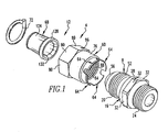
- Fig. 1 is an exploded perspective view of an improved coupling in accordance with the present invention
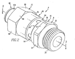
- Fig. 2 is a perspective view of the coupling in a partially assembled condition
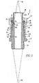
- Fig. 3 is a sectional view as taken along line 3-3 of Fig. 2;
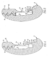
- Fig. 4 is an enlarged view of a portion of Fig. 3, i.e., with the coupling in a partially assembled condition;
- Fig. 5 is a view similar to Fig. 4, except depicting the coupling in an assembled condition.
- FIG. 1-5 An improved coupling 4 in accordance with the present invention is indicated generally in Figs. 1-5.
- the coupling 4 is advantageously configured to provide a substantially leak-free seal between various components of a hydraulic circuit and to resists loosening in the presence of elevated and changing temperatures, pressures and vibration. While the exemplary fluid circuit described herein is a hydraulic circuit, it is noted that the coupling 4 can be employed in other fluid circuits, whether or not the fluid circuits are closed or open, i.e., whether or not they are continuous.
- the coupling 4 of the present invention advantageously includes a self-locking feature that resists loosening during use in its intended environment, as will be described in greater detail below.
- the coupling 4 can be considered to include a fitting 8 and a nut 12.
- the fitting 8 and the nut 12 are threadably connectable together pursuant to the formation of the substantially leak-free seal therebetween.
- a first component (not expressly depicted) of a fluid circuit is associated with the fitting 8
- a second component (not expressly depicted) of the fluid circuit is associated with the nut 12, and when the fitting 8 and the nut 12 are connected together in the manner set forth below, the first and second components of the fluid circuit will be in substantially leak-free fluid communication with one another.
- the fitting 8 includes a barrel 16, a first nipple 20, and a second nipple 24.
- the barrel 16 can be said to be disposed between the first and second nipples 20 and 24.
- the first nipple 20 protrudes in a first direction away from the barrel 16, and the second nipple 24 protrudes in a second, opposite direction away from the barrel 16.
- the exemplary coupling 4 depicted therein includes the first and second nipples 20 and 24 being of different configurations.
- the first nipple 20 is, as will be set forth in greater detail herein, threadably cooperable with the nut 12.
- the second nipple 24 is of a different configuration than the first nipple 20, and is configured to be threadably cooperable with a threaded hole formed in a manifold or other structure.
- the coupling 4 could include a pair of nipples that are each cooperable with nuts without departing from the concept of the present invention.
- the barrel 16 includes an external surface 28 upon which are formed a plurality of flats 32 that function as engageable structures that are engageable by an appropriate tool such as a wrench or spanner.
- the barrel 16 additionally includes an annular shelf 36 (Figs. 3-5) adjacent the external surface 28.
- a groove 40 is formed in the barrel adjacent the shelf 36, and the groove 40 includes a laterally disposed engagement surface 44 that is undercut in the region below the shelf 36, as can be best understood from Figs. 4 and 5.
- the engagement surface 44 faces generally radially inwardly and is of a substantially frusto-conic shape that includes a first vertex 48 disposed at a position spaced in the aforementioned first direction from the barrel 16. It is understood that expressions such as “below”, “above”, “inwardly”, “outwardly”, and the like, as well as variations thereof, as used herein are not intended to be limiting.
- the first nipple 20 includes external threading 52, and further includes a first seal surface 56 at the free end of the first nipple 20 opposite the barrel 16.
- the first seal surface 56 is of a substantially frusto-conic shape.
- the nut 12 can be broadly described as including a collar 60, a plurality of fingers 64, a ferrule 68, and a thrust wire 72.
- the collar 60 and the fingers 64 are formed as a monolithic single-piece member.
- the collar 60 includes an outer surface 76 upon which are formed a plurality of flats 80 that serve as engageable structures that are engageable by an appropriate tool such as a wrench or spanner. As is best shown in Fig. 3, the collar 60 additionally includes an inner surface 84 upon which is formed internal threading 88. The inner surface 84 additionally includes a substantially annular channel 92 formed therein, and the channel 92 is in communication with a hole 96 (Fig. 1) that is formed in the collar 60 and extends from the channel 92 to the outer surface 76 of the collar 60. The thrust wire 72 is disposed in the channel 92 and in the hole 96.
- Each finger 64 includes an elongated bar 100 (Figs. 4 and 5) and a projection 104.
- the bars 100 extend in a direction generally parallel with one another and parallel with the longitudinal extent with the collar 60 from an end of the collar 60 generally opposite the channel 92.
- Each projection 104 is disposed on its corresponding bar 100 at the free end of the bar 100 opposite the collar 60.
- Each projection 104 includes a first surface 108 and a second surface 112 that intersect one another at an arcuate edge 116.
- the first surfaces 108 extend generally radially outwardly, i.e., with respect to the longitudinal extent of the collar 60, from the bars 100.
- the first surfaces 108 are, in the depicted embodiment, oriented roughly perpendicular to the longitudinal extent of the bar and, in the exemplary coupling 4 depicted herein, lie in a common plane.
- the second surfaces 112 each face generally outwardly from the nut 12.
- the second surfaces 112 are of a substantially frusto-conic configuration, meaning that the second surfaces 112 lie on a common frusto-conic shape.
- the frusto-conic shape of the second surfaces 112 has a second vertex 120 (Fig. 3) that is disposed at a location spaced in the aforementioned second direction from the barrel 16.
- the ferrule 68 includes a tube portion 124 and a flange 128 connected together.
- the flange 128 provides a lip 130 (Fig. 3) extending generally from the tube portion 124.
- the ferrule 68 includes a second seal surface 132 that is of a substantially frusto-conic shape.
- the first and second seal surfaces 56 and 132 are sealingly engageable with one another when the nut 12 is mounted on the first nipple 20.
- a first component of the fluid circuit such as a piece of tubing (not shown) is received between the lip 130 and the thrust wire 72 and is tightly affixed therebetween in a sealing fashion when the nut 12 is threadably tightened on the fitting 8 as will be described in greater detail below.
- the flange 128 can be said to be engageable with the thrust wire 72, albeit with a piece of tubing or other structure disposed therebetween.
- the fingers 64 are elastically deflectable from a free state, i.e., an undeflected state, as is depicted generally in Fig. 1.
- the fingers 64 are in an elastically deflected condition when the coupling is assembled, such as is shown in Fig. 5, and also is in an elastically deflected condition during at least a portion of the assembly and disassembly of the coupling 4, as can be understood generally upon consideration of a transition in the condition of the coupling 4 between the condition depicted in Fig. 4 and that in Fig. 5.
- the expression “partially assembled” and the like may refer generally to a condition in which the nut 12 and the fitting 8 are threadably connected together yet with the fingers 64 disengaged from the engagement surface 44, and it is further noted that the expression “assembled” may refer generally to a condition in which the fingers 64 are engaged with the engagement surface 44 with the coupling 4 torqued to an appropriate level.
- the fingers 64 approach the groove 40 in an undeflected condition until the second surfaces 112 engage the barrel 16 at the region of intersection between the shelf 36 and the engagement surface 44. Further threading of the fitting 8 and the nut 12 from such point causes the fingers 64 to elastically deflect from their free state, as can be understood from Figs. 4 and 5.
- Such threaded advancement of the nut 12 onto the fitting 8 causes progressively greater elastic deflection of the fingers 64 until the edges 116 have advanced past the shelf 36 and are engaged with the engagement surface 44.
- Such progressive elastic deflection of the fingers 64 prior to the point at which the edges 116 engage the engagement surface 44 results from the frusto-conic shape of the second surfaces 112 having the second vertex 120 spaced in the second direction from the barrel 16.
- the elastic deflection of the fingers 64 advantageously continuously and progressively increases if the nut 12 is moved in an unthreading direction from an assembled condition, i.e., such as when the coupling 4 is disassembled.
- Such progressively increased deflection of the fingers 64 results in progressively increased engagement forces between the edges 116 and the engagement surface 44, thereby progressively increasing the frictional forces between the edges 116 and the engagement surface 44.
- Such frictional forces resist movement of the nut 12 in an unthreading direction with respect to the fitting 8.
- Such progressively increasing elastic deflection and frictional forces result from the frusto-conic shape of the engagement surface 44 having its first vertex 48 at the location spaced in the first direction from the barrel 16.
- the second surfaces 112 are oriented at a reverse angle with respect to the engagement surface 44 which permits the edges 116 to frictionally engage the engagement surface 44.
- the forces seeking to unintentionally move the nut 12 in the unthreading direction such as forces caused by temperatures, pressures, and vibration
- overcome the initial frictional engagement between the edges 116 and the engagement surface 44 the resultant unthreading of the nut 12 will progressively increase the frictional resistance to such unthreading until such unintentional unthreading ceases.
- the various angles and deflection forces of the structures described herein can be tailored to provide specific properties for use in specific applications.
- the edges 116 remain continuously in contact with the engagement surface 44 in initially moving the coupling 4 in the unthreading direction from the assembled condition. Such continuity of contact promotes the progressive nature of the increase in frictional forces during initial unthreading of the coupling 4.
- the initial frictional resistance to unthreading provided in the fully assembled condition, and the progressively increasing frictional resistance during unthreading, are advantageously in stark contrast to other systems which permit a certain amount of free loosening before any structures resist loosening, and further are in advantageous stark contrast to other systems in which frictional resistance to unthreading decreases upon initial unthreading of a nut.
- the frictional resistance referred to herein applies both to static friction as well as dynamic friction, in comparison with static and dynamic friction in other coupling devices, and it is further noted that the unintended unthreading of a nut as a result of temperatures, pressures, and vibration, typically will be a function of static friction properties, although this may not always be the case.
Landscapes
- Engineering & Computer Science (AREA)
- General Engineering & Computer Science (AREA)
- Mechanical Engineering (AREA)
- Gasket Seals (AREA)
- Joints With Pressure Members (AREA)
- Fluid-Pressure Circuits (AREA)
- Mechanical Operated Clutches (AREA)
- Hydraulic Clutches, Magnetic Clutches, Fluid Clutches, And Fluid Joints (AREA)
Abstract
Description
- The present invention relates generally to hydraulic fittings and, more particularly, to a self-locking hydraulic fitting.
- Various types of fluid couplings are employed in fluid circuits. Such fluid couplings are typically employed to connect together separate components of a fluid system, such as when a first tube is connected together with a second tube or with another structure such as a manifold block. Such fluid couplings generally are designed to provide substantially leak-free seals between connected components in a given environment.
- Fluid couplings often include components that are tightly threaded together to provide the substantially leak-free seal. The threaded configuration of the components permits them to be easily connected together to assemble the hydraulic circuit, and are readily separated from one another, such as when the various components of the hydraulic circuit are in need of inspection, maintenance, and/or replacement.
- One such type of environment in which fluid couplings are employed is in a hydraulic circuit. Hydraulic circuits typically involve the transfer of fluids at high temperatures and pressures in the presence of extreme vibrations. While known hydraulic couplings have been generally effective for their intended purposes, such hydraulic couplings have not been without limitation.
- The high vibration environment of a hydraulic circuit, combined with the expansions and contractions of the components of a hydraulic circuit resulting from temperature changes and high pressures, causes the threaded portions of hydraulic fittings to gradually loosen, i.e., unthread, over time. Generally any loosening of a coupling will result in a leakage of the fluid from within the circuit, and progressively greater degrees of loosening typically cause progressively greater rates of fluid loss. It is thus highly desirable to provide a hydraulic fitting with a self-locking feature that resists unthreading in the typical hydraulic environment of high temperatures, pressures, and vibration. Examples of known self-locking fluid couplings are disclosed in documents US 6 302 497 and US 5 388 866. The US 6 302 447 discloses the preamble of claim 1.
- An improved hydraulic coupling in accordance with the present invention meets and exceeds these and other needs. An improved hydraulic coupling includes a fitting and a nut that are threadably connectable together. The fitting includes a generally annular groove having a lateral frusto-conic engagement surface. The nut includes a plurality of elongated fingers that each include a projection having an outwardly-disposed edge. When the coupling is assembled, the edges are frictionally engaged with the engagement surface as a result of the elastic deflection of the fingers. The frusto-conic shape of the engagement surface provides progressively greater frictional resistance in a direction of unthreading of the coupling, whereby loosening of the coupling during operation of the fluid circuit is resisted.
- Accordingly, an aspect of the present invention is to provide an improved coupling that provides a substantially leak-free seal between components of a fluid circuit.
- Another aspect of the present invention is to provide an improved coupling that resists loosening in an environment of elevated and varying temperatures, pressures, and vibration.
- Another aspect of the present invention is to provide an improved coupling having a plurality of fingers with protrusions that are frictionally engaged with a frusto-conic surface of another structure to provide progressively increasing frictional resistance in an unthreading direction.
- Accordingly, an aspect of the present invention is to provide an improved coupling, the general nature of which can be stated as including a fitting and a nut. The fitting has a barrel, an externally threaded first nipple, and a second nipple. The first nipple protrudes away from the barrel in a first direction, and the second nipple protrudes away from the barrel in a second direction. The barrel includes an external surface that is structured to be engaged by a tool, and further includes an annular shelf disposed adjacent the external surface and a groove formed therein adjacent the shelf. The groove has an engagement surface that is undercut below the shelf and that is of a first frusto-conic shape that faces generally radially inwardly. The nut includes an internally threaded collar and a plurality of elongated fingers extending from the collar. The collar has an outer surface that is structured to be engaged by a tool. Each finger includes a deflectable bar and a projection. The projections each include a first surface and a second surface, with the first surface extending generally radially outwardly from the bar and being oriented generally perpendicular to the longitudinal extent of the bar, and with the second surface being of a second frusto-conic shape and facing generally radially outwardly, the first and second surfaces meeting at an edge. The first nipple and the collar are structured to be threadably connected together. The engagement surface has a vertex spaced from the barrel in the first direction, and the second surface has a vertex spaced from the barrel in the second direction. The bars are structured to be elastically deflected inwardly from a free state and the edges are structured to be frictionally engaged with the engagement surface when the coupling is assembled.
- A further understanding of the invention can be gained from the following Description of the Preferred Embodiment when read in conjunction with the accompanying drawings in which:
- Fig. 1 is an exploded perspective view of an improved coupling in accordance with the present invention;
- Fig. 2 is a perspective view of the coupling in a partially assembled condition;
- Fig. 3 is a sectional view as taken along line 3-3 of Fig. 2;
- Fig. 4 is an enlarged view of a portion of Fig. 3, i.e., with the coupling in a partially assembled condition; and
- Fig. 5 is a view similar to Fig. 4, except depicting the coupling in an assembled condition.
- Similar numerals refer to similar parts throughout the specification.
- An improved coupling 4 in accordance with the present invention is indicated generally in Figs. 1-5. The coupling 4 is advantageously configured to provide a substantially leak-free seal between various components of a hydraulic circuit and to resists loosening in the presence of elevated and changing temperatures, pressures and vibration. While the exemplary fluid circuit described herein is a hydraulic circuit, it is noted that the coupling 4 can be employed in other fluid circuits, whether or not the fluid circuits are closed or open, i.e., whether or not they are continuous. The coupling 4 of the present invention advantageously includes a self-locking feature that resists loosening during use in its intended environment, as will be described in greater detail below.
- In the broadest sense, the coupling 4 can be considered to include a fitting 8 and a
nut 12. Thefitting 8 and thenut 12 are threadably connectable together pursuant to the formation of the substantially leak-free seal therebetween. As can be understood, a first component (not expressly depicted) of a fluid circuit is associated with thefitting 8, and a second component (not expressly depicted) of the fluid circuit is associated with thenut 12, and when thefitting 8 and thenut 12 are connected together in the manner set forth below, the first and second components of the fluid circuit will be in substantially leak-free fluid communication with one another. - The
fitting 8 includes abarrel 16, afirst nipple 20, and asecond nipple 24. Thebarrel 16 can be said to be disposed between the first andsecond nipples first nipple 20 protrudes in a first direction away from thebarrel 16, and thesecond nipple 24 protrudes in a second, opposite direction away from thebarrel 16. - As can be seen from Fig. 1, the exemplary coupling 4 depicted therein includes the first and
second nipples first nipple 20 is, as will be set forth in greater detail herein, threadably cooperable with thenut 12. Thesecond nipple 24 is of a different configuration than thefirst nipple 20, and is configured to be threadably cooperable with a threaded hole formed in a manifold or other structure. It is noted that in other embodiments of the present invention the coupling 4 could include a pair of nipples that are each cooperable with nuts without departing from the concept of the present invention. - The
barrel 16 includes anexternal surface 28 upon which are formed a plurality offlats 32 that function as engageable structures that are engageable by an appropriate tool such as a wrench or spanner. Thebarrel 16 additionally includes an annular shelf 36 (Figs. 3-5) adjacent theexternal surface 28. Agroove 40 is formed in the barrel adjacent theshelf 36, and thegroove 40 includes a laterally disposedengagement surface 44 that is undercut in the region below theshelf 36, as can be best understood from Figs. 4 and 5. Theengagement surface 44 faces generally radially inwardly and is of a substantially frusto-conic shape that includes afirst vertex 48 disposed at a position spaced in the aforementioned first direction from thebarrel 16. It is understood that expressions such as "below", "above", "inwardly", "outwardly", and the like, as well as variations thereof, as used herein are not intended to be limiting. - The
first nipple 20 includesexternal threading 52, and further includes afirst seal surface 56 at the free end of thefirst nipple 20 opposite thebarrel 16. Thefirst seal surface 56 is of a substantially frusto-conic shape. - The
nut 12 can be broadly described as including acollar 60, a plurality offingers 64, aferrule 68, and athrust wire 72. In the exemplary embodiment depicted herein, thecollar 60 and thefingers 64 are formed as a monolithic single-piece member. - The
collar 60 includes anouter surface 76 upon which are formed a plurality offlats 80 that serve as engageable structures that are engageable by an appropriate tool such as a wrench or spanner. As is best shown in Fig. 3, thecollar 60 additionally includes aninner surface 84 upon which is formedinternal threading 88. Theinner surface 84 additionally includes a substantiallyannular channel 92 formed therein, and thechannel 92 is in communication with a hole 96 (Fig. 1) that is formed in thecollar 60 and extends from thechannel 92 to theouter surface 76 of thecollar 60. Thethrust wire 72 is disposed in thechannel 92 and in thehole 96. - Each
finger 64 includes an elongated bar 100 (Figs. 4 and 5) and aprojection 104. Thebars 100 extend in a direction generally parallel with one another and parallel with the longitudinal extent with thecollar 60 from an end of thecollar 60 generally opposite thechannel 92. Eachprojection 104 is disposed on its correspondingbar 100 at the free end of thebar 100 opposite thecollar 60. Eachprojection 104 includes afirst surface 108 and asecond surface 112 that intersect one another at anarcuate edge 116. Thefirst surfaces 108 extend generally radially outwardly, i.e., with respect to the longitudinal extent of thecollar 60, from thebars 100. Thefirst surfaces 108 are, in the depicted embodiment, oriented roughly perpendicular to the longitudinal extent of the bar and, in the exemplary coupling 4 depicted herein, lie in a common plane. - The
second surfaces 112 each face generally outwardly from thenut 12. thesecond surfaces 112 are of a substantially frusto-conic configuration, meaning that thesecond surfaces 112 lie on a common frusto-conic shape. The frusto-conic shape of thesecond surfaces 112 has a second vertex 120 (Fig. 3) that is disposed at a location spaced in the aforementioned second direction from thebarrel 16. - The
ferrule 68 includes atube portion 124 and aflange 128 connected together. Theflange 128 provides a lip 130 (Fig. 3) extending generally from thetube portion 124. Theferrule 68 includes asecond seal surface 132 that is of a substantially frusto-conic shape. - As can be understood from Fig. 3, the first and second seal surfaces 56 and 132 are sealingly engageable with one another when the
nut 12 is mounted on thefirst nipple 20. A first component of the fluid circuit, such as a piece of tubing (not shown) is received between thelip 130 and thethrust wire 72 and is tightly affixed therebetween in a sealing fashion when thenut 12 is threadably tightened on the fitting 8 as will be described in greater detail below. As such, theflange 128 can be said to be engageable with thethrust wire 72, albeit with a piece of tubing or other structure disposed therebetween. - The
fingers 64 are elastically deflectable from a free state, i.e., an undeflected state, as is depicted generally in Fig. 1. Thefingers 64 are in an elastically deflected condition when the coupling is assembled, such as is shown in Fig. 5, and also is in an elastically deflected condition during at least a portion of the assembly and disassembly of the coupling 4, as can be understood generally upon consideration of a transition in the condition of the coupling 4 between the condition depicted in Fig. 4 and that in Fig. 5. It is noted that the expression "partially assembled" and the like may refer generally to a condition in which thenut 12 and thefitting 8 are threadably connected together yet with thefingers 64 disengaged from theengagement surface 44, and it is further noted that the expression "assembled" may refer generally to a condition in which thefingers 64 are engaged with theengagement surface 44 with the coupling 4 torqued to an appropriate level. When thenut 12 and thefitting 8 are being threadably connected, thefingers 64 approach thegroove 40 in an undeflected condition until thesecond surfaces 112 engage thebarrel 16 at the region of intersection between theshelf 36 and theengagement surface 44. Further threading of thefitting 8 and thenut 12 from such point causes thefingers 64 to elastically deflect from their free state, as can be understood from Figs. 4 and 5. Such threaded advancement of thenut 12 onto the fitting 8 causes progressively greater elastic deflection of thefingers 64 until theedges 116 have advanced past theshelf 36 and are engaged with theengagement surface 44. Such progressive elastic deflection of thefingers 64 prior to the point at which theedges 116 engage theengagement surface 44 results from the frusto-conic shape of thesecond surfaces 112 having thesecond vertex 120 spaced in the second direction from thebarrel 16. - Once the
edges 116 are engaged with theengagement surface 44, further threaded advancement of thenut 12 onto the fitting 8 results in reduced elastic deflection of thefingers 64 due to the undercut configuration of theengagement surface 44 in the region below theshelf 36. It is noted, however, that even upon fully assembling the coupling 4, such as depicted in Fig. 5, thefingers 64 are still in a condition elastically deflected from their free state such that theedges 116 remain frictionally engaged with theengagement surface 44. - It can further be understood from Fig. 5 that the elastic deflection of the
fingers 64 advantageously continuously and progressively increases if thenut 12 is moved in an unthreading direction from an assembled condition, i.e., such as when the coupling 4 is disassembled. Such progressively increased deflection of thefingers 64 results in progressively increased engagement forces between theedges 116 and theengagement surface 44, thereby progressively increasing the frictional forces between theedges 116 and theengagement surface 44. Such frictional forces resist movement of thenut 12 in an unthreading direction with respect to thefitting 8. Such progressively increasing elastic deflection and frictional forces result from the frusto-conic shape of theengagement surface 44 having itsfirst vertex 48 at the location spaced in the first direction from thebarrel 16. Thesecond surfaces 112 are oriented at a reverse angle with respect to theengagement surface 44 which permits theedges 116 to frictionally engage theengagement surface 44. - It thus can be seen that the frictional forces that resist unthreading of the
nut 12 progressively increase with increased unthreading until such unthreading has progressed to the point that theedges 116 are beyond the range of theengagement surface 44. Such progressively increased resistance in the unthreading direction advantageously resists unintended loosening of the coupling 4 during operation as a result of elevated and/or changing pressures, temperatures, and vibration. The frictional engagement of theedges 116 with theengagement surface 44 when the coupling 4 is fully assembled provides a certain level of frictional resistance to movement of thenut 12 in the unthreading direction. If the forces seeking to unintentionally move thenut 12 in the unthreading direction, such as forces caused by temperatures, pressures, and vibration, overcome the initial frictional engagement between theedges 116 and theengagement surface 44, the resultant unthreading of thenut 12 will progressively increase the frictional resistance to such unthreading until such unintentional unthreading ceases. In this regard, it is understood that the various angles and deflection forces of the structures described herein can be tailored to provide specific properties for use in specific applications. Further in this regard, it is noted that theedges 116 remain continuously in contact with theengagement surface 44 in initially moving the coupling 4 in the unthreading direction from the assembled condition. Such continuity of contact promotes the progressive nature of the increase in frictional forces during initial unthreading of the coupling 4. - The initial frictional resistance to unthreading provided in the fully assembled condition, and the progressively increasing frictional resistance during unthreading, are advantageously in stark contrast to other systems which permit a certain amount of free loosening before any structures resist loosening, and further are in advantageous stark contrast to other systems in which frictional resistance to unthreading decreases upon initial unthreading of a nut. In this regard, it is noted that the frictional resistance referred to herein applies both to static friction as well as dynamic friction, in comparison with static and dynamic friction in other coupling devices, and it is further noted that the unintended unthreading of a nut as a result of temperatures, pressures, and vibration, typically will be a function of static friction properties, although this may not always be the case.
- While specific embodiments of the invention have been described in detail, it will be appreciated by those skilled in the art that various modifications and alternatives to those details could be developed in light of the overall teachings of the disclosure. Accordingly, the particular arrangements disclosed are meant to be illustrative only and not limiting as to the scope of the invention which is to be given the full breadth of the claims appended.
Claims (5)
- A coupling (4) comprising:a fitting (8) having a barrel (16), an externally threaded first nipple (20), and a second nipple (24), the first nipple (20) protruding away from the barrel (16) in a first direction, the second nipple (24) protruding away from the barrel (16) in a second direction, the barrel (16) having an external surface (28) that is structured to be engaged by a tool, the barrel (16) including an annular shelf (36) disposed adjacent the external surface (28), the barrel (16) having a groove (40) formed therein adjacent the shelf (36), the groove (40) having an engagement surface (44)a nut (12) including an internally threaded collar (60) and a plurality of elongated fingers (64) extending from the collar (60), the collar (60) having an outer surface (76) that is structured to be engaged by a tool, each finger (64) including a deflectable bar (100) and a projection (104), the projections (104) each including a first surface (108) and a second surface (112),the first nipple (20) and the collar (60) being structured to be threadably connected together;the engagement surface (44) having a vertex (48) spaced from the barrel (16) in the first direction;the second surface (112) having a vertex spaced from the barrel (16) in the second direction; andcharacterized in that the engagement surface (44) is undercut below the shelf (36) and is of a first frusto-conic shape that faces generally radially inwardly, in that the first surface (108) extends generally radially outwardly from the bar (100) and is oriented generally perpendicular to the longitudinal extent of the bar (100), the second surface (112) being of a second frusto-conic shape and facing generally radially outwardly, the first (108) and second (112) surfaces meeting at an edge (116); and in thatthe bars (100) are structured to be elastically deflected inwardly from a free state and the edges (116) are structured to be frictionally engaged with the engagement surface (44) when the coupling (4) is assembled.
- The coupling of Claim 1 wherein
the nut (12) includes a ferrule (68) having a tube portion (124) and an outwardly protruding flange (128) ;
the collar (60) including an internal stop member (72); and
the flange (128) being structured to be engaged with the stop member (72). - The coupling of Claim 2 wherein
the stop member (72) a thrust wire (72) disposed internally on the collar (60). - The coupling of Claim 2 wherein
the first nipple (20) includes an exterior frusto-conic seal surface (56);
the ferrule (68) including an interior frusto-conic seat surface (132); and
the exterior (56) and interior (132) seal surfaces being sealingly engaged with one another. - The coupling of Claim 1 wherein
the bars (100) are structured to be continuously and progressively elastically deflected inwardly when the coupling (4) is moved in an unthreading direction from an assembled condition.
Applications Claiming Priority (2)
| Application Number | Priority Date | Filing Date | Title |
|---|---|---|---|
| US10/669,734 US6905142B2 (en) | 2002-09-25 | 2003-09-24 | Hydraulic coupling |
| US669734 | 2003-09-24 |
Publications (2)
| Publication Number | Publication Date |
|---|---|
| EP1519093A1 EP1519093A1 (en) | 2005-03-30 |
| EP1519093B1 true EP1519093B1 (en) | 2007-02-28 |
Family
ID=34194809
Family Applications (1)
| Application Number | Title | Priority Date | Filing Date |
|---|---|---|---|
| EP04021498A Expired - Lifetime EP1519093B1 (en) | 2003-09-24 | 2004-09-09 | Hydraulic coupling |
Country Status (5)
| Country | Link |
|---|---|
| US (1) | US6905142B2 (en) |
| EP (1) | EP1519093B1 (en) |
| JP (1) | JP4589685B2 (en) |
| AT (1) | ATE355485T1 (en) |
| DE (1) | DE602004004966T2 (en) |
Families Citing this family (35)
| Publication number | Priority date | Publication date | Assignee | Title |
|---|---|---|---|---|
| GB0221076D0 (en) * | 2002-09-11 | 2002-10-23 | Guest John Int Ltd | Improvements in or relating to tube couplings |
| JP4229775B2 (en) * | 2003-07-18 | 2009-02-25 | イハラサイエンス株式会社 | Pipe fitting |
| US7506901B2 (en) * | 2004-07-14 | 2009-03-24 | Robert Pinckney | Resilient locking connection |
| US7793989B2 (en) * | 2004-07-14 | 2010-09-14 | Pinckney Jr Robert | Locking connector with depressions |
| ITMI20051383A1 (en) * | 2005-07-20 | 2007-01-21 | Faster Spa | SAFETY DEVICE FOR ASSEMBLED PARTS WITH THREAD RELATIVE TO A QUICK COUPLING |
| SE531367C2 (en) * | 2007-04-05 | 2009-03-10 | Tomas Haakansson | Hydraulic |
| JP4589955B2 (en) * | 2007-12-19 | 2010-12-01 | 積水化学工業株式会社 | Connection structure between tubular connecting member and joint member |
| US20090315327A1 (en) * | 2008-06-23 | 2009-12-24 | Christopher David Plucker | Anti-rotation locking device for tube unions |
| KR101633947B1 (en) | 2008-12-10 | 2016-06-27 | 스와겔로크 컴패니 | Ferrule assembly for conduit fitting |
| US8157294B2 (en) * | 2009-12-10 | 2012-04-17 | Masco Corporation | Glueless whirlpool fittings |
| WO2011091008A1 (en) | 2010-01-21 | 2011-07-28 | Swagelok Company | Conduit gripping device having retaining structure for conduit fitting |
| US20120001425A1 (en) * | 2010-07-02 | 2012-01-05 | Frank Ching King Lee | Fluid Line Connecting Fitting |
| CN102985740B (en) | 2010-07-09 | 2016-01-06 | 世伟洛克公司 | Pipe fittings with flexible torque collars |
| US20120103575A1 (en) * | 2010-11-03 | 2012-05-03 | Hon Hai Precision Industry Co., Ltd. | Cooling device |
| US9303800B2 (en) * | 2010-11-12 | 2016-04-05 | Fluidmaster, Inc. | Torque limiting fluid connector system |
| US20130092271A1 (en) * | 2011-10-14 | 2013-04-18 | Colder Products Company | Coupling |
| US9342077B2 (en) * | 2011-11-04 | 2016-05-17 | Saint-Gobain Performance Plastics Corporation | System, method and apparatus for plumbing fitting with removable sampling valve |
| FR2987881B1 (en) * | 2012-03-07 | 2014-03-14 | Jpb Systeme | SECURE CONNECTION DEVICE, IN PARTICULAR FOR PIPING, TIP FOR THIS DEVICE AND METHOD FOR MANUFACTURING AN ASSOCIATED NUT. |
| US8641099B2 (en) * | 2012-07-05 | 2014-02-04 | United Technologies Corporation | Coupling with one-piece plural nipples |
| US9726309B1 (en) * | 2013-03-13 | 2017-08-08 | Mercury Plastics, Inc. | Tube connection nut and ferrule assembly |
| US9279526B2 (en) * | 2013-03-14 | 2016-03-08 | Mcalister Technologies, Llc | Apparatuses and methods for providing finger-tightened and ratchet-secured connections between conduits |
| US9885433B2 (en) * | 2013-09-04 | 2018-02-06 | Baker Hughes | Vibration-resistant boltless ESP component connection |
| US11262013B2 (en) | 2014-01-14 | 2022-03-01 | The Boeing Company | Tube fitting |
| US10060563B2 (en) | 2014-01-14 | 2018-08-28 | The Boeing Company | Tube fitting |
| US10359141B2 (en) | 2014-01-14 | 2019-07-23 | The Boeing Company | Tube fitting |
| US9939095B2 (en) * | 2014-01-29 | 2018-04-10 | The Boeing Company | Tube fitting |
| RU2678474C2 (en) | 2014-05-09 | 2019-01-29 | Своджлок Компани | Conduit fitting with components adapted for facilitating assembly |
| KR102351742B1 (en) * | 2016-03-23 | 2022-01-14 | 스웨이지락 캄파니 | Conduit Fittings with Stroke Resistance Features |
| US11408540B2 (en) | 2017-09-27 | 2022-08-09 | General Electric Company | Tube coupling assembly |
| US11703165B2 (en) | 2018-04-27 | 2023-07-18 | Swagelok Company | Ferrule assembly for conduit fitting |
| KR102323543B1 (en) * | 2021-02-18 | 2021-11-09 | 에스앤씨코퍼레이션 주식회사 | Pipe piping coupler |
| US11698153B2 (en) * | 2021-09-24 | 2023-07-11 | Caterpillar Inc. | Fluid joint assembly adjustable from primary to backup sealing state and fluid connector for same |
| FR3128981B1 (en) * | 2021-11-09 | 2023-12-22 | Safran Aircraft Engines | Element for connecting a bearing support to an oil pipe tube and turbomachine equipped with such a connection element |
| FR3134610B1 (en) * | 2022-04-15 | 2024-04-19 | Safran Aircraft Engines | Element for connecting a pipe tube to a bearing support and turbomachine equipped with such a connection element. |
| US20260109185A1 (en) * | 2024-10-23 | 2026-04-23 | The Legion Engineering Corporation | Tire valve |
Family Cites Families (13)
| Publication number | Priority date | Publication date | Assignee | Title |
|---|---|---|---|---|
| US1312584A (en) * | 1919-08-12 | Coupling device | ||
| US2992018A (en) * | 1957-06-03 | 1961-07-11 | Rosan Eng Corp | Self locking threaded coupling |
| NL6516151A (en) | 1965-12-11 | 1967-06-12 | ||
| GB1140606A (en) * | 1966-06-03 | 1969-01-22 | Cannon Electric Great Britain | Coupling arrangement for two cylindrical members |
| US4265470A (en) * | 1979-09-21 | 1981-05-05 | Cameron Iron Works, Inc. | Tubular connector |
| US5058930A (en) | 1990-03-09 | 1991-10-22 | Lourdes Industries | High pressure coupling with provision for preventing separation of parts and with anti-galling provision |
| US5388866A (en) | 1990-03-09 | 1995-02-14 | Lourdes Industries | High pressure coupling with provision for preventing separation of parts and with anti-galling provision |
| US5083819A (en) | 1991-02-25 | 1992-01-28 | Moeller Manufacturing Co. | Fluid coupling and fastener capture device |
| US5362110A (en) | 1991-02-25 | 1994-11-08 | Moeller Manufacturing Co., Inc. | Fluid coupling and fastener capture device |
| JP2549747Y2 (en) * | 1992-11-05 | 1997-09-30 | 積水化学工業株式会社 | Pipe fittings |
| US6302447B1 (en) * | 1999-06-11 | 2001-10-16 | Airdrome Parts Co. | Self-locking coupling device |
| US6299225B1 (en) * | 1999-09-28 | 2001-10-09 | Chih Chung Chang | Electrical lock device |
| FR2832207B1 (en) | 2001-11-14 | 2005-02-25 | Gazinox S A | SAFETY DEVICE FOR PROTECTING A PIPE CONNECTION TO AN ORGAN SUCH AS A FAUCET |
-
2003
- 2003-09-24 US US10/669,734 patent/US6905142B2/en not_active Expired - Lifetime
-
2004
- 2004-09-01 JP JP2004253760A patent/JP4589685B2/en not_active Expired - Fee Related
- 2004-09-09 AT AT04021498T patent/ATE355485T1/en not_active IP Right Cessation
- 2004-09-09 EP EP04021498A patent/EP1519093B1/en not_active Expired - Lifetime
- 2004-09-09 DE DE602004004966T patent/DE602004004966T2/en not_active Expired - Lifetime
Also Published As
| Publication number | Publication date |
|---|---|
| JP4589685B2 (en) | 2010-12-01 |
| US6905142B2 (en) | 2005-06-14 |
| ATE355485T1 (en) | 2006-03-15 |
| DE602004004966D1 (en) | 2007-04-12 |
| JP2005098501A (en) | 2005-04-14 |
| HK1074072A1 (en) | 2005-10-28 |
| US20040056481A1 (en) | 2004-03-25 |
| EP1519093A1 (en) | 2005-03-30 |
| DE602004004966T2 (en) | 2007-11-08 |
Similar Documents
| Publication | Publication Date | Title |
|---|---|---|
| US6905142B2 (en) | Hydraulic coupling | |
| US7568737B2 (en) | Male coupling for connecting to female threaded coupling | |
| EP0439328B1 (en) | Tube coupling | |
| KR0173473B1 (en) | Fluid coupling with gasket retainer | |
| CA2514289C (en) | An adjusting unit for adjusting a spacing between two members | |
| AU2007300473B2 (en) | Male coupling for connecting to female threaded coupling | |
| US20050151370A1 (en) | Lockwireless anti-rotation fitting | |
| US6688651B2 (en) | Device for locking cap nut for coupling | |
| US7600789B2 (en) | Lockwireless anti-rotation fitting | |
| CN110735978A (en) | Coupling for fluid line assembly | |
| US6123317A (en) | Coupling | |
| US20080018107A1 (en) | Coupling assembly and retainer for use with same | |
| JP4901861B2 (en) | Air spring assembly with non-screw connection | |
| US20080174108A1 (en) | Snap-in-place valved coupler | |
| EP1914457A1 (en) | Fluid controller with joint | |
| US6019558A (en) | Nut and bolt securing device | |
| AU2005209763B2 (en) | Coupling assembly | |
| US20060082151A1 (en) | Coupling assembly with connection indicator | |
| HK1074072B (en) | Hydraulic coupling | |
| US6715801B2 (en) | Safety quick connection | |
| US5564754A (en) | Reusable union coupling | |
| US5000490A (en) | Adapter fitting | |
| IT1252000B (en) | FEMALE FITTING FOR VARIOUS FLUIDS | |
| JP4437553B2 (en) | Manifold block and valve unit using the same | |
| US5649797A (en) | Nut and bolt securing device |
Legal Events
| Date | Code | Title | Description |
|---|---|---|---|
| PUAI | Public reference made under article 153(3) epc to a published international application that has entered the european phase |
Free format text: ORIGINAL CODE: 0009012 |
|
| 17P | Request for examination filed |
Effective date: 20050120 |
|
| AK | Designated contracting states |
Kind code of ref document: A1 Designated state(s): AT BE BG CH CY CZ DE DK EE ES FI FR GB GR HU IE IT LI LU MC NL PL PT RO SE SI SK TR |
|
| AX | Request for extension of the european patent |
Extension state: AL HR LT LV MK |
|
| REG | Reference to a national code |
Ref country code: HK Ref legal event code: DE Ref document number: 1074072 Country of ref document: HK |
|
| AKX | Designation fees paid |
Designated state(s): AT BE BG CH CY CZ DE DK EE ES FI FR GB GR HU IE IT LI LU MC NL PL PT RO SE SI SK TR |
|
| GRAP | Despatch of communication of intention to grant a patent |
Free format text: ORIGINAL CODE: EPIDOSNIGR1 |
|
| GRAS | Grant fee paid |
Free format text: ORIGINAL CODE: EPIDOSNIGR3 |
|
| GRAA | (expected) grant |
Free format text: ORIGINAL CODE: 0009210 |
|
| AK | Designated contracting states |
Kind code of ref document: B1 Designated state(s): AT BE BG CH CY CZ DE DK EE ES FI FR GB GR HU IE IT LI LU MC NL PL PT RO SE SI SK TR |
|
| PG25 | Lapsed in a contracting state [announced via postgrant information from national office to epo] |
Ref country code: DK Free format text: LAPSE BECAUSE OF FAILURE TO SUBMIT A TRANSLATION OF THE DESCRIPTION OR TO PAY THE FEE WITHIN THE PRESCRIBED TIME-LIMIT Effective date: 20070228 Ref country code: SI Free format text: LAPSE BECAUSE OF FAILURE TO SUBMIT A TRANSLATION OF THE DESCRIPTION OR TO PAY THE FEE WITHIN THE PRESCRIBED TIME-LIMIT Effective date: 20070228 Ref country code: CH Free format text: LAPSE BECAUSE OF FAILURE TO SUBMIT A TRANSLATION OF THE DESCRIPTION OR TO PAY THE FEE WITHIN THE PRESCRIBED TIME-LIMIT Effective date: 20070228 Ref country code: PL Free format text: LAPSE BECAUSE OF FAILURE TO SUBMIT A TRANSLATION OF THE DESCRIPTION OR TO PAY THE FEE WITHIN THE PRESCRIBED TIME-LIMIT Effective date: 20070228 Ref country code: AT Free format text: LAPSE BECAUSE OF FAILURE TO SUBMIT A TRANSLATION OF THE DESCRIPTION OR TO PAY THE FEE WITHIN THE PRESCRIBED TIME-LIMIT Effective date: 20070228 Ref country code: NL Free format text: LAPSE BECAUSE OF FAILURE TO SUBMIT A TRANSLATION OF THE DESCRIPTION OR TO PAY THE FEE WITHIN THE PRESCRIBED TIME-LIMIT Effective date: 20070228 Ref country code: FI Free format text: LAPSE BECAUSE OF FAILURE TO SUBMIT A TRANSLATION OF THE DESCRIPTION OR TO PAY THE FEE WITHIN THE PRESCRIBED TIME-LIMIT Effective date: 20070228 Ref country code: BE Free format text: LAPSE BECAUSE OF FAILURE TO SUBMIT A TRANSLATION OF THE DESCRIPTION OR TO PAY THE FEE WITHIN THE PRESCRIBED TIME-LIMIT Effective date: 20070228 Ref country code: LI Free format text: LAPSE BECAUSE OF FAILURE TO SUBMIT A TRANSLATION OF THE DESCRIPTION OR TO PAY THE FEE WITHIN THE PRESCRIBED TIME-LIMIT Effective date: 20070228 |
|
| REG | Reference to a national code |
Ref country code: GB Ref legal event code: FG4D |
|
| REG | Reference to a national code |
Ref country code: CH Ref legal event code: EP |
|
| REF | Corresponds to: |
Ref document number: 602004004966 Country of ref document: DE Date of ref document: 20070412 Kind code of ref document: P |
|
| REG | Reference to a national code |
Ref country code: IE Ref legal event code: FG4D |
|
| PG25 | Lapsed in a contracting state [announced via postgrant information from national office to epo] |
Ref country code: BG Free format text: LAPSE BECAUSE OF FAILURE TO SUBMIT A TRANSLATION OF THE DESCRIPTION OR TO PAY THE FEE WITHIN THE PRESCRIBED TIME-LIMIT Effective date: 20070529 |
|
| PG25 | Lapsed in a contracting state [announced via postgrant information from national office to epo] |
Ref country code: SE Free format text: LAPSE BECAUSE OF FAILURE TO SUBMIT A TRANSLATION OF THE DESCRIPTION OR TO PAY THE FEE WITHIN THE PRESCRIBED TIME-LIMIT Effective date: 20070531 |
|
| PG25 | Lapsed in a contracting state [announced via postgrant information from national office to epo] |
Ref country code: ES Free format text: LAPSE BECAUSE OF FAILURE TO SUBMIT A TRANSLATION OF THE DESCRIPTION OR TO PAY THE FEE WITHIN THE PRESCRIBED TIME-LIMIT Effective date: 20070608 |
|
| PG25 | Lapsed in a contracting state [announced via postgrant information from national office to epo] |
Ref country code: PT Free format text: LAPSE BECAUSE OF FAILURE TO SUBMIT A TRANSLATION OF THE DESCRIPTION OR TO PAY THE FEE WITHIN THE PRESCRIBED TIME-LIMIT Effective date: 20070730 |
|
| NLV1 | Nl: lapsed or annulled due to failure to fulfill the requirements of art. 29p and 29m of the patents act | ||
| REG | Reference to a national code |
Ref country code: CH Ref legal event code: PL |
|
| REG | Reference to a national code |
Ref country code: HK Ref legal event code: GR Ref document number: 1074072 Country of ref document: HK |
|
| PG25 | Lapsed in a contracting state [announced via postgrant information from national office to epo] |
Ref country code: SK Free format text: LAPSE BECAUSE OF FAILURE TO SUBMIT A TRANSLATION OF THE DESCRIPTION OR TO PAY THE FEE WITHIN THE PRESCRIBED TIME-LIMIT Effective date: 20070228 |
|
| PG25 | Lapsed in a contracting state [announced via postgrant information from national office to epo] |
Ref country code: CZ Free format text: LAPSE BECAUSE OF FAILURE TO SUBMIT A TRANSLATION OF THE DESCRIPTION OR TO PAY THE FEE WITHIN THE PRESCRIBED TIME-LIMIT Effective date: 20070228 Ref country code: RO Free format text: LAPSE BECAUSE OF FAILURE TO SUBMIT A TRANSLATION OF THE DESCRIPTION OR TO PAY THE FEE WITHIN THE PRESCRIBED TIME-LIMIT Effective date: 20070228 |
|
| PLBE | No opposition filed within time limit |
Free format text: ORIGINAL CODE: 0009261 |
|
| STAA | Information on the status of an ep patent application or granted ep patent |
Free format text: STATUS: NO OPPOSITION FILED WITHIN TIME LIMIT |
|
| 26N | No opposition filed |
Effective date: 20071129 |
|
| PG25 | Lapsed in a contracting state [announced via postgrant information from national office to epo] |
Ref country code: MC Free format text: LAPSE BECAUSE OF NON-PAYMENT OF DUE FEES Effective date: 20070930 Ref country code: GR Free format text: LAPSE BECAUSE OF FAILURE TO SUBMIT A TRANSLATION OF THE DESCRIPTION OR TO PAY THE FEE WITHIN THE PRESCRIBED TIME-LIMIT Effective date: 20070529 Ref country code: IT Free format text: LAPSE BECAUSE OF FAILURE TO SUBMIT A TRANSLATION OF THE DESCRIPTION OR TO PAY THE FEE WITHIN THE PRESCRIBED TIME-LIMIT Effective date: 20070228 |
|
| PG25 | Lapsed in a contracting state [announced via postgrant information from national office to epo] |
Ref country code: IE Free format text: LAPSE BECAUSE OF NON-PAYMENT OF DUE FEES Effective date: 20070910 |
|
| PG25 | Lapsed in a contracting state [announced via postgrant information from national office to epo] |
Ref country code: EE Free format text: LAPSE BECAUSE OF FAILURE TO SUBMIT A TRANSLATION OF THE DESCRIPTION OR TO PAY THE FEE WITHIN THE PRESCRIBED TIME-LIMIT Effective date: 20070228 |
|
| GBPC | Gb: european patent ceased through non-payment of renewal fee |
Effective date: 20080909 |
|
| PG25 | Lapsed in a contracting state [announced via postgrant information from national office to epo] |
Ref country code: CY Free format text: LAPSE BECAUSE OF FAILURE TO SUBMIT A TRANSLATION OF THE DESCRIPTION OR TO PAY THE FEE WITHIN THE PRESCRIBED TIME-LIMIT Effective date: 20070228 |
|
| PG25 | Lapsed in a contracting state [announced via postgrant information from national office to epo] |
Ref country code: LU Free format text: LAPSE BECAUSE OF NON-PAYMENT OF DUE FEES Effective date: 20070909 |
|
| PG25 | Lapsed in a contracting state [announced via postgrant information from national office to epo] |
Ref country code: TR Free format text: LAPSE BECAUSE OF FAILURE TO SUBMIT A TRANSLATION OF THE DESCRIPTION OR TO PAY THE FEE WITHIN THE PRESCRIBED TIME-LIMIT Effective date: 20070228 Ref country code: HU Free format text: LAPSE BECAUSE OF FAILURE TO SUBMIT A TRANSLATION OF THE DESCRIPTION OR TO PAY THE FEE WITHIN THE PRESCRIBED TIME-LIMIT Effective date: 20070901 |
|
| PG25 | Lapsed in a contracting state [announced via postgrant information from national office to epo] |
Ref country code: GB Free format text: LAPSE BECAUSE OF NON-PAYMENT OF DUE FEES Effective date: 20080909 |
|
| PGFP | Annual fee paid to national office [announced via postgrant information from national office to epo] |
Ref country code: DE Payment date: 20140922 Year of fee payment: 11 |
|
| PGFP | Annual fee paid to national office [announced via postgrant information from national office to epo] |
Ref country code: FR Payment date: 20140919 Year of fee payment: 11 |
|
| REG | Reference to a national code |
Ref country code: DE Ref legal event code: R119 Ref document number: 602004004966 Country of ref document: DE |
|
| REG | Reference to a national code |
Ref country code: FR Ref legal event code: ST Effective date: 20160531 |
|
| PG25 | Lapsed in a contracting state [announced via postgrant information from national office to epo] |
Ref country code: DE Free format text: LAPSE BECAUSE OF NON-PAYMENT OF DUE FEES Effective date: 20160401 |
|
| PG25 | Lapsed in a contracting state [announced via postgrant information from national office to epo] |
Ref country code: FR Free format text: LAPSE BECAUSE OF NON-PAYMENT OF DUE FEES Effective date: 20150930 |