EP1519083A1 - Operating position select device for automatic transmission - Google Patents
Operating position select device for automatic transmission Download PDFInfo
- Publication number
- EP1519083A1 EP1519083A1 EP04292320A EP04292320A EP1519083A1 EP 1519083 A1 EP1519083 A1 EP 1519083A1 EP 04292320 A EP04292320 A EP 04292320A EP 04292320 A EP04292320 A EP 04292320A EP 1519083 A1 EP1519083 A1 EP 1519083A1
- Authority
- EP
- European Patent Office
- Prior art keywords
- assist
- select
- select lever
- operating
- angle
- Prior art date
- Legal status (The legal status is an assumption and is not a legal conclusion. Google has not performed a legal analysis and makes no representation as to the accuracy of the status listed.)
- Withdrawn
Links
- 230000005540 biological transmission Effects 0.000 title claims abstract description 37
- 230000008878 coupling Effects 0.000 claims abstract description 30
- 238000010168 coupling process Methods 0.000 claims abstract description 30
- 238000005859 coupling reaction Methods 0.000 claims abstract description 30
- 230000007246 mechanism Effects 0.000 description 26
- 230000033001 locomotion Effects 0.000 description 23
- 238000000034 method Methods 0.000 description 9
- 230000008569 process Effects 0.000 description 9
- 230000008859 change Effects 0.000 description 8
- 238000010586 diagram Methods 0.000 description 6
- OKTJSMMVPCPJKN-UHFFFAOYSA-N Carbon Chemical compound [C] OKTJSMMVPCPJKN-UHFFFAOYSA-N 0.000 description 5
- 229910052799 carbon Inorganic materials 0.000 description 5
- 238000006243 chemical reaction Methods 0.000 description 5
- 238000009434 installation Methods 0.000 description 4
- 230000001133 acceleration Effects 0.000 description 3
- 230000004044 response Effects 0.000 description 3
- 238000006073 displacement reaction Methods 0.000 description 2
- 230000010354 integration Effects 0.000 description 2
- 230000004048 modification Effects 0.000 description 2
- 238000012986 modification Methods 0.000 description 2
- 230000007935 neutral effect Effects 0.000 description 2
- 230000002093 peripheral effect Effects 0.000 description 2
- 230000009467 reduction Effects 0.000 description 2
- 238000010276 construction Methods 0.000 description 1
- 230000003111 delayed effect Effects 0.000 description 1
- 238000004904 shortening Methods 0.000 description 1
- 239000000758 substrate Substances 0.000 description 1
Images



Classifications
-
- F—MECHANICAL ENGINEERING; LIGHTING; HEATING; WEAPONS; BLASTING
- F16—ENGINEERING ELEMENTS AND UNITS; GENERAL MEASURES FOR PRODUCING AND MAINTAINING EFFECTIVE FUNCTIONING OF MACHINES OR INSTALLATIONS; THERMAL INSULATION IN GENERAL
- F16H—GEARING
- F16H61/00—Control functions within control units of change-speed- or reversing-gearings for conveying rotary motion ; Control of exclusively fluid gearing, friction gearing, gearings with endless flexible members or other particular types of gearing
- F16H61/26—Generation or transmission of movements for final actuating mechanisms
- F16H61/28—Generation or transmission of movements for final actuating mechanisms with at least one movement of the final actuating mechanism being caused by a non-mechanical force, e.g. power-assisted
- F16H61/32—Electric motors , actuators or related electrical control means therefor
-
- F—MECHANICAL ENGINEERING; LIGHTING; HEATING; WEAPONS; BLASTING
- F16—ENGINEERING ELEMENTS AND UNITS; GENERAL MEASURES FOR PRODUCING AND MAINTAINING EFFECTIVE FUNCTIONING OF MACHINES OR INSTALLATIONS; THERMAL INSULATION IN GENERAL
- F16H—GEARING
- F16H59/00—Control inputs to control units of change-speed- or reversing-gearings for conveying rotary motion
- F16H59/02—Selector apparatus
- F16H59/08—Range selector apparatus
- F16H59/10—Range selector apparatus comprising levers
- F16H59/105—Range selector apparatus comprising levers consisting of electrical switches or sensors
-
- F—MECHANICAL ENGINEERING; LIGHTING; HEATING; WEAPONS; BLASTING
- F16—ENGINEERING ELEMENTS AND UNITS; GENERAL MEASURES FOR PRODUCING AND MAINTAINING EFFECTIVE FUNCTIONING OF MACHINES OR INSTALLATIONS; THERMAL INSULATION IN GENERAL
- F16H—GEARING
- F16H61/00—Control functions within control units of change-speed- or reversing-gearings for conveying rotary motion ; Control of exclusively fluid gearing, friction gearing, gearings with endless flexible members or other particular types of gearing
- F16H61/26—Generation or transmission of movements for final actuating mechanisms
- F16H61/28—Generation or transmission of movements for final actuating mechanisms with at least one movement of the final actuating mechanism being caused by a non-mechanical force, e.g. power-assisted
- F16H61/32—Electric motors , actuators or related electrical control means therefor
- F16H2061/323—Electric motors , actuators or related electrical control means therefor for power assistance, i.e. servos with follow up action
-
- F—MECHANICAL ENGINEERING; LIGHTING; HEATING; WEAPONS; BLASTING
- F16—ENGINEERING ELEMENTS AND UNITS; GENERAL MEASURES FOR PRODUCING AND MAINTAINING EFFECTIVE FUNCTIONING OF MACHINES OR INSTALLATIONS; THERMAL INSULATION IN GENERAL
- F16H—GEARING
- F16H61/00—Control functions within control units of change-speed- or reversing-gearings for conveying rotary motion ; Control of exclusively fluid gearing, friction gearing, gearings with endless flexible members or other particular types of gearing
- F16H61/26—Generation or transmission of movements for final actuating mechanisms
- F16H61/28—Generation or transmission of movements for final actuating mechanisms with at least one movement of the final actuating mechanism being caused by a non-mechanical force, e.g. power-assisted
- F16H61/32—Electric motors , actuators or related electrical control means therefor
- F16H2061/326—Actuators for range selection, i.e. actuators for controlling the range selector or the manual range valve in the transmission
-
- Y—GENERAL TAGGING OF NEW TECHNOLOGICAL DEVELOPMENTS; GENERAL TAGGING OF CROSS-SECTIONAL TECHNOLOGIES SPANNING OVER SEVERAL SECTIONS OF THE IPC; TECHNICAL SUBJECTS COVERED BY FORMER USPC CROSS-REFERENCE ART COLLECTIONS [XRACs] AND DIGESTS
- Y10—TECHNICAL SUBJECTS COVERED BY FORMER USPC
- Y10T—TECHNICAL SUBJECTS COVERED BY FORMER US CLASSIFICATION
- Y10T74/00—Machine element or mechanism
- Y10T74/20—Control lever and linkage systems
- Y10T74/20012—Multiple controlled elements
- Y10T74/20018—Transmission control
-
- Y—GENERAL TAGGING OF NEW TECHNOLOGICAL DEVELOPMENTS; GENERAL TAGGING OF CROSS-SECTIONAL TECHNOLOGIES SPANNING OVER SEVERAL SECTIONS OF THE IPC; TECHNICAL SUBJECTS COVERED BY FORMER USPC CROSS-REFERENCE ART COLLECTIONS [XRACs] AND DIGESTS
- Y10—TECHNICAL SUBJECTS COVERED BY FORMER USPC
- Y10T—TECHNICAL SUBJECTS COVERED BY FORMER US CLASSIFICATION
- Y10T74/00—Machine element or mechanism
- Y10T74/20—Control lever and linkage systems
- Y10T74/20012—Multiple controlled elements
- Y10T74/20018—Transmission control
- Y10T74/2003—Electrical actuator
Definitions
- the present invention relates to an operating position select device for an automatic transmission by which a driver can select by operating a select lever one of select mode positions corresponding to a plurality of operation modes of the automatic transmission.
- This select device includes a select lever unit disposed near a driver's seat in a passenger compartment and a mode shift unit mounted on an automatic transmission.
- the select lever unit has a select lever manually operated by a driver and is connected with the mode shift unit by a connecting mechanism, such as a control cable, or a connecting linkage, which transmits an operating force applied on the select lever by the driver to the mode shift unit to shift operation modes of the automatic transmission.
- the conventional art has a problem that the select lever unit needs a long select lever in order to operate it without a large operating force of the driver, which reduces design freedom concerning to an installation location of the select lever unit and/or a layout of a passenger compartment.
- This select device is, what is called, a shift-by-wire type one. It has a select lever manually operated by a driver, a select position detector for detecting a position of the select lever, a mode shift unit mounted on an automatic transmission for shifting its operation modes, an electric motor for driving a mode shift unit, and a control unit for controlling the electric motor based on an output signal from the detector.
- This select device is suitable for shortening a length of the select lever and expanding design freedom for its installation location and/or layout of a passenger compartment, while the select device lacks a mechanical connection between the select lever and the mode shift unit. This lack of the mechanical connection results in that the mode shift unit can not be sifted despite of operating the select lever in case of electrical failure such that an electric wire is broken, or the select position detector or the control unit fails.
- an object of the present invention to provide an operating position select device for an automatic transmission which overcomes the foregoing drawbacks and can expand design freedom concerning to layout of a passenger compartment and/or an installation location of a select lever unit and drive a mode shift unit despite of electric failure of the operating position select device.
- an operating position select device for an automatic transmission comprising: a select lever unit having a select lever operated by a driver; an operating position sensor which detects an operating position of the select lever and outputs an operating position signal; a mode shift unit mounted on the automatic transmission to shift operation modes of the automatic transmission; a mechanically connecting means which mechanically connects the select lever and the mode shift unit with each other; an assist actuator which is arranged between said select lever and said mode shift unit and outputs assist torque to an intermediate portion of said mechanically connecting means to shift the mode shift unit; an assist position sensor which detects an assist position of the assist actuator and outputs an assist position signal; and a control unit which computes a non-coupling amount of the mechanically connecting means to determine a compensation amount and generate a compensation signal concerning the compensation amount and controls drive current supplied to the assist actuator based on the operating position signal, the assist position signal, and the compensation signal.
- the compensation amount is set to be smaller than the non-coupling amount.
- the compensation amount is set to be substantially a half of the non-coupling amount.
- the non-coupling amount includes non-coupling amounts both in a first select direction of the select lever and in a second select direction opposite to the first select direction.
- the non-coupling amount is detected when the select lever is held in one of select mode positions corresponding to the operation modes of the automatic transmission.
- an automatic transmission 19 which is a conventional multi-speed one with a plurality of planetary gear sets, not shown, and operated among a plurality of operation modes, for example, a parking mode, a reverse drive mode, a neutral mode, a forward drive mode, and a forward low geared drive mode.
- the automatic transmission 19 is provided with an operating position select device 100, which shifts the operation modes to a desirable mode by a manually select operation of a select lever 2 of the select device 100.
- the operating position select device 100 includes a select lever unit 1 manually operated by a driver, an operating angle sensor 51 for detecting an operating angle of the select lever 2, an mode shift unit 300 mounted on the automatic transmission 19, a first and second control cables 8 and 18 connecting the select lever 2 and the mode shift unit 300 with each other, an assist actuator 9 for assisting operating force inputted to the select lever unit 1, an assist angle sensor 200 for detecting an assist angle, and a control unit 22 for controlling the assist actuator 9.
- the operating angle sensor 51 corresponds to an operating position sensor of the present invention
- the assist angle sensor 200 corresponds to an assist position sensor of the present invention.
- the operating angle corresponds to an operating position of the present invention
- the assist angle corresponds to an assist position of the present invention.
- the control unit 22 is electrically connected to a power supply PS and ground GND.
- the operating angle sensor 51 and the assist angle sensor 200 are electrically connected to the control unit 22.
- the select lever unit 1 is arranged, for example, at a center console 3 beside a driver's seat and has the select lever 2, a bracket 5 fixed to a vehicle body, a supporting shaft 5a fixed on the bracket 5 to swingably support the select lever 2, a knob 4 mounted on the top of the select lever 2, and a checking mechanism, not shown, for ensuring the select lever 2 to be kept in a selected mode position.
- the select lever 2 is set to about 100 mm in length in this embodiment, which is designed to be shorter by about 250 mm than a conventional type select lever.
- the lever 2 is operated by the driver swingably in a first direction toward P position as indicated by an arrow B P and a second direction opposite to the P position and toward L position as indicated by an arrow B L .
- the select lever 2 can be positioned in one of select mode positions: the P position corresponding to the parking mode of the automatic transmission 19, an R position corresponding to the reverse drive mode, an N position corresponding to the neutral mode, a D position corresponding to the forward drive mode, and the L position corresponding to the forward low geared drive mode.
- the operating angle sensor 51 is electrically connected to the control unit 22 and detects an operating angle of the select lever 2 to output an operating angle signal to the control unit 22.
- FIG. 6 shows a relationship between the operating angle of the select lever 2 and sensing current outputted from the operating angle sensor 51 as the operating angle signal.
- the sensing current outputted from the operating angle sensor 51 is proportional to the operating angle, both of which increase when the select lever 2 moves toward the R position.
- the operating angle signal corresponds to an operating position signal of the present invention.
- the mode shift unit 300 shifts the operation modes of the automatic transmission 19 according to a movement of the select lever 2 through the first and second control cables 8 and 18.
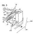
- the mode shift unit 300 has a manual plate lever 20 and a detent mechanism for keeping the manual plate lever 20 in a selected one of the select mode positions.
- the manual plate lever 20 is fixed on its intermediate portion with a rotary shaft 26 to be rotatable together with the shaft 26.
- the second control cable 18 is connected with one end portion of the manual plate lever 20 to control a rotation angle of the manual plate lever 20.
- the rotary shaft 26 is fixed with a detent plate 27 of the detent mechanism.
- the detent plate 27 is connected with a valve spool 310 of a manual valve disposed in a control valve unit of the automatic transmission 19 so as to move the spool 300 to shift the manual valve.
- the detent plate 27 has a cam that is formed on its upper peripheral portions with top portions 27a and bottom portions 27b.
- the bottoms of the bottom portions 27b are arranged between the adjacent top portions 27a respectively. Positions of the bottom portions 27b correspond respectively to the five operation modes of the automatic transmission 19.
- the cam is pressed by a detent pin 29 urged by a spring plate 28.
- One end portion of the spring plate 28 is mounted on the control valve unit and the other end portion supports the detent pin 29.
- the detent pin 29 is formed at a tip of the spring plate 28 to be pressed onto the cam of the detent plate 27 to be positioned in one of the bottom portions 27b so as to detain the valve spool 310 of the manual valve in a selected mode position.
- the detent plate 27 that is formed with the top and bottom portions 27a and 27b, the detent pin 29, and the spring plate 28 correspond to a detent mechanism of the present invention.
- the detent plate 27 is coupled at its cam side portion with a parking rod 30 having a wedge 30a biased by a coil spring 30b.
- the wedge 30a can move along the rod 30 and press a parking pawl 31 by spring force of the coil spring 30b to engage the pawl 31 with a parking wheel 32 united to an output shaft of the automatic transmission 19 when the select lever 2 is shifted to the P position. This engagement of the pawl 31 and the wheel 32 results in locking drive wheels of a vehicle for parking.
- the detent plate 27 and the select lever 2 are, as shown in FIG 1, mechanically connected with the first and second control cables 8 and 18, and others.
- the first control cable 8 connects at its one end portion with a bottom portion of the select lever 2 through a first joint 7 and at the other end portion with one end portion of an input lever 10 through a second joint 11.
- the other end portion of the input lever 10 is connected with a top portion of a coupling shaft 12, whose bottom portion is connected with one end portion of an output lever 13.
- the other end portion of the output lever 13 is connected with one end portion of the second control cable 18 through a third joint 17.
- the other end portion of the second control cable 18 is, as shown in FIGS. 1 and 3, connected with the manual plate lever 20.
- the first and second control cables 8 and 18, the first to third joints 7, 11, and 17, the input and output plates 10 and 13, and the coupling shaft 12 correspond to a mechanically connecting means of the present invention.
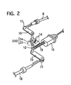
- the assist actuator 9 as shown in FIG. 1 and especially in FIG. 2, includes an electric motor 15 with reduction gears to reduce rotation speed of an output shaft of the motor 15, a worm 16 that is formed on the output shaft, and a worm wheel 14 that is in mesh with the worm 16 and united to the coupling shaft 12.
- the worm wheel 14 is provided on its upper surface with an electric terminal 24 contacted to a carbon resistor 25 indicated by a dashed line in FIG. 2.
- the carbon resistor 25 is printed on a substrate fixed to a case of the assist actuator 9.
- the electric terminal 24 and the carbon resistor 25 constitute the assist angle sensor 200, which is electrically connected to the control unit 22.
- the electric terminal 24 is movable together with and around the coupling shaft 12 by moving the select lever 2 to change its position with respect to the carbon resistor 25 and output an assisting angle signal to the control unit 22.
- FIG 6 shows a relationship between the assist angle of the coupling shaft 12 and sensing current outputted from the assist angle sensor 200 as the assist angle signal.
- the sensing current outputted from the assist angle sensor 200 is proportional to the assist angle, both of which increase when the select lever 2 moves toward the R position.
- the assist angle sensor 200 corresponds to an assist position sensor of the present invention
- the assist angle signal corresponds to an assist position signal of the present invention.
- the assist angle sensor 200 and the motor 15 are electrically connected to the control unit 22.
- the control unit 22 receives the operating angle signal outputted from the operating angle sensor 51 and the assist angle signal outputted from the assist angle sensor 200 to compute target assist current based on these signals, and drives the electric motor 15 under pulse width modulation (PWM) control based on the target assist current.
- PWM pulse width modulation
- FIG 4 shows a control block diagram of the control unit 22 and its related units.
- a select operation by a driver causes that operating force of the driver inputs the select lever 2 to change its operating angle.
- the operating force is transmitted to the first control cable 8 and the checking mechanism.
- the operating angle is detected by the operating angle sensor 51, which outputs an operating angle signal to the control unit 22.
- the first control cable 18 rotates the worm wheel 14 united with the coupling shaft 12 to move the terminal 24 with respect to the carbon resistance 25.
- This relative angle between the terminal 24 and the resistance 25 is detected by the assist angle sensor 200 as an assist angle, and the sensor 200 outputs an assist angle signal to the control unit 22.
- the coupling shaft 12 drives the second control cable 18 to shift the mode sift unit 300 of the automatic transmission 19.
- An operating speed and direction judgment part 33 computes the operating angle of the select lever 2 based on the operating angle signal outputted from the operating angle sensor 51 and the assist angle signal outputted from the assist angle sensor 200. Then, the operating speed and direction judgment part 33 computes an operating speed and judges an operating direction of the select lever 2 by calculating differential of the operating angles, and then outputs an operating speed signal and an operating direction signal to an alignment error compensation part 52 and a feedforward (FF) control table part 42.
- FF feedforward
- the alignment error compensation part 52 computes an alignment error and outputs a compensation signal to a first adder 54 to compensate the signals outputted from the operating angle sensor 51 and the assist angle sensor 200.
- the alignment error 1 is computed in a state such that it can be apparently confirmed where the select lever 2 is positioned, for example, in the P position.
- the feedforward control table part 42 has a plurality of feedforward compensation tables which determine feedforward current based on the operating angle, the assist angle, the operating speed, and the operating direction to output a feedforward current signal to a fourth adder 41.
- the tables are prepared according to the respective operating directions, the directions B P and B L of the select lever 2 shown in FIG 1, and their data are set so that the feedforward current becomes larger as the operating speed becomes higher.
- the first adder 54 computes an angle difference between the operating angle and the assist angle in view of the alignment error based on the operating angle signal, the assist angle signal, and the compensation signal to output an angle difference signal to a target speed generation part 34.
- the target speed generation part 34 receives the angle difference signal and computes a target speed of the select lever 2 based on the angle difference to output a target speed signal to a second adder 35.
- a differential element 53 receives the assist angle signal outputted from the assist angle sensor 200 to obtain an assist speed by calculating differential of the assist angles and outputs an assist speed signal to a second adder 35.
- the second adder 35 receives the assist speed signal and computes a speed difference between the assist speed obtained by the differential part 53 and the target speed obtained by the target speed generation part 34 to output a speed difference signal to a feedback (FB) control part 36.
- FB feedback
- the feedback control part 36 includes a first multiplier 37, a third adder 38, a second multiplier 39 and an integral element 40.
- the first multiplier 37 computes a proportional current by multiplying the speed difference, obtained from the second adder 35, by a proportional gain and outputs a proportional current signal to the third adder 38.
- the second multiplier 39 computes a multiplied speed difference current by multiplying the speed difference obtained from the second adder 35 by integral gain and outputs a multiplied speed difference current signal to the integral element 40.
- the integral element 40 obtains integral current by calculating integration of the multiplied speed difference current and outputs an integral current signal to the third adder 38.
- the third adder 38 computes feedback current iFB by adding the integral current to the proportional current and outputs a feedback current signal to the fourth adder 41.
- the fourth adder 41 computes motor drive current by adding the feedforward current signal to the feedback current signal and outputs a motor drive current signal to a motor drive control part 45.
- the motor drive control part 45 outputs the motor drive current to the electric motor 15 under Power Width Modulation (PWM) control.
- PWM Power Width Modulation
- the motor 15 may be driven under current control or armature voltage control.
- a compensation part 55 detects a non-coupling amount when the select lever 2 is moved from a position where the select lever 2 is held in one of the select mode positions to determine a compensation amount and output a compensation signal concerning to the compensation amount to the first adder 54 based upon an operating angle signal, an assist angle signal, and an operating direction signal.
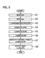
- FIG. 5 shows a flowchart of an assist process executed in the control unit 22 to control the assist actuator 9 when the select lever 2 is operated.
- control unit 22 receives an operating angle signal outputted from the operating angle sensor 51 to read an operating angle AOP of the select lever 2, and then the flow goes to step S2.
- control unit 22 receives an assist angle signal outputted from the assist angle sensor 200 to read an assist angle ASL of the coupling shaft 12 assisted by the assist actuator 9, and then the flow goes to step S3.
- the compensation part 55 determines a compensation amount based on the operating angle signal outputted from the operating angle sensor 51, the assist angle signal outputted from the assist angle sensor 200, and an operating direction signal outputted from the operating speed and direction judgment part 33 so as to output a compensation signal to the first adder 54, and then the flow goes to step S4. How to determine the compensation amount will be described in detail later.
- the first adder 54 computes an angle difference ⁇ AG between the operating angle AOP and the assist angle ASL in consideration of the compensation amount, and then the flow goes to step S5.
- the target generation part 34 determines targeted speed STAR of the select lever 2 based on the angle difference ⁇ AG, and then the flow goes to step S6.
- the feedback control part 36 computes the feedback current iFB, and then the flow goes to step S7.
- the FF control table part 43 shifts the feedforward compensation tables so as to select and refer an optimum table according to the operating direction of the select lever 2 and the operating angle. Then, the FF control table part 43 computes feedforward current iFF by using the selected optimum FF control table, and then the flow goes to step S8.
- the fourth adder 38 computes motor drive current iMOT by adding the compensated feedforward current iCOM to the feedback current iFB so as to output the motor drive current iMOT to the motor drive control part 45. This output the motor drive current iMOT brings the electric motor 15b to run to assist the select operation of the select lever 2.
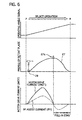
- FIG. 6 shows relationships of an operating angle current signal, a profile of the detent plate 27, and motor drive current with respect to a travel amount, corresponding to the operating angle, when the select lever 2 is shifted from the P position to the R position.
- the operating angle signal outputted from the operating angle sensor 51 increases proportionally as the operating angle of the select lever 2 increases.
- the detent pin 29, as shown in the intermediate part of FIG 6, ascends from the bottom portion 27b of the detent plate 27 to the top portion 27a, which causes resistance force against the operating force applied on the select lever 2 by a driver to become larger at first and then descends.
- This change of the resistance force demands the motor drive current iMOT to rise at first stage and then descend according to the resistance force.
- the motor drive current iMOT is shown in the lower part of FIG. 6 and includes FF assist current iFF which is indicated by a dashed line.
- the FF assist current iFF is set to about a half value of the motor drive current iMOT, so that assist torque obtained by the current iFF corresponds to reaction torque caused at the detent mechanism.
- the detent pin 29 comes in the pull-in zone. In this zone, the detent pin 29 is biased by the spring plate 28 to move into the bottom portion 27b corresponding to the R position, where the assist control is stopped.
- the select lever 2 is assisted to move in the operating direction by the electric motor 15 driven by the FB assist current iFB and the FF assist current iFF.
- This assist control of the motor 15 using the both assist currents iFB and iFF is superior to assist control using only one of the assist currents. This reason comes from following descriptions.
- the assist control of this embodiment can satisfy all of suitable assist torque, high response to large reaction force, and high robust stability, because the motor drive current iMOT includes both of the FB assist current IFB that is determined based on a speed difference between actual operating speed of the select lever 2 and target operating speed and the FF assist current iFF that is of a half value of electric current corresponding to the reaction torque of the detent mechanism.
- the operation of the select lever 2 is immediately detected by the operating angle sensor 51, while the assist control movement is not detected immediately by the assist angle sensor 200 because of existence of play, loose, and/or deformation of the control cables 8 and 18 and the others. Accordingly, a target speed is computed based on an angle difference between the operating angle and the assist angle, and then a speed difference between the target speed and an assist speed of the assist actuator 9 is computed to determine the FB assist current and its assist direction.
- the FB assist current is set to be larger as at least one of the angle difference, the speed difference, and an acceleration difference between the select lever 2 and the coupling shaft 12 becomes larger.
- the FF assist current is added to the FB assist current to improve a response.
- This assist operation by the assist actuator 9 enables the manual plate lever 20 to move synchronously with and follow the select lever 4, although the first control cable 8 is loosened, which results in reducing the operating force.
- This reduction of the operating force emphasizes detent feeling, caused by the detent mechanism, to the driver and provides a good operation feeling.
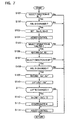
- the operating speed and direction judgment part 33 detects an operating direction of the select lever 2 operated by the driver based on the operating angle AOP obtained from the operating angle sensor 51 and the assist angle ASL obtained from the assist angle sensor 200. Then the judgment part 33 judges whether or not the select lever 2 is moved toward the L position, which is indicated by the arrow BL in FIG. 1. If YES, the flow goes to step S102, while, if No, the execution of this process is ended.
- the compensation part 55 determines whether or not the assist angle ASL outputted from the assist angle sensor 200 is changed. If YES, the flow goes to step S103, while, if NO, the execution of this process is ended.
- Xa is set to be zero and Xb is set to be zero, where Xa is an operating angle just before the assist angle ASL changes, and Xb is an assist angle just before the assist angle ASL changes, and then the flow goes to step S 104.
- step S104 the assist control is carried out according to the flow shown in FIG. 5, and then the flow goes to step S105.
- the compensation part 55 judges whether or not the select lever 2 is in a state of being held at one of the bottom portions 27b corresponding to the select mode positions of the automatic transmission, such as the R, P, N, D, and L positions. If YES, the flow goes to step S106, while, if NO, the execution of this process is ended.
- step S106 the angle positions of the Xa' and Xb' are recorded in a memory of the control unit 22, where Xa' is an operating angle AOP when the select lever 2 is held in the select mode position, and Xb' is an assist angle ASL when the select lever 2 is held in the select mode position, and then the flow goes to step S 107.
- the compensation part 55 judges based on the operating direction obtained from the operating speed and direction judgment part 33 whether or not the select lever 2 is moved toward the P position, which is indicated by the arrow BP in FIG. 1. If YES, the flow goes to step S108, while, if NO, the execution of this process is ended.
- step S108 it is judged whether or not the assist angle ASL outputted from the assist angle sensor 200 is changed. If YES, the flow goes to step S109, while, if NO, the execution of this process is ended.
- Xa" and Xb" are recorded in the memory, where Xa" is an operating angle just before the assist angle ASL changes, and Xb" is an assist angle just before the assist angle ASL changes, and then the flow goes to step S110.
- step S111 it is judged whether or not the sum of the lost motion amount and the play amount. If YES, the flow goes to step S112, while, if No, the flow goes to step S 114.
- the compensation part 55 outputs a compensation signal corresponding to the median M to the first adder 54 to compensate its output signal, and then the flow goes to the step S 114.
- step S114 the assist control according to the flow shown in FIG. 5 is carried out in consideration of the above computed compensation.
- FIGS. 8 and 9 show a state of a mechanically connecting mechanism 400 when the select lever 2 is held in one of the select mode positions or moved from to another select mode position.
- the control cables 8 and the others, such as the fist and second joints 7 and 19, and the input lever 10, between the sensors 51 and 200 are schematically illustrated in FIGS. 8 and 9 as the mechanically connecting mechanism 400, which has a first transmitting member 410 connected with the select lever 2, a second transmitting member 420 connected with the coupling shaft 12, and a length changing part 430.
- the mechanically connecting mechanism 400 corresponds to a mechanically connecting means of the present invention.
- the first and second transmitting members 410 and 420 and the length changing part 430 are positioned in a state shown in FIG 8.
- the length changing part 430 has a lost motion amount and/or a play amount in the both directions BP and BL, which allows the select lever 2 to be substantially free from restriction by the first and second transmitting members 410 and 420.
- the lost motion amount and/or the play amount correspond to a non-coupling amount of the present invention.
- the operating speed and direction judgment 33 judges its operating direction, which corresponds to the step S101 in FIG. 7.
- an operating angle signal AOP outputted from the operating angle sensor 51 changes, while an assist angle signal ASL outputted from the assist angle sensor 200 does not change because of existence of the lost motion and/or the play at the length changing part 430.
- the length changing part 430 of the mechanically connecting mechanism 400 has a lost motion amount and/or a play amount in the both directions B L and B P as shown in the intermediate part of FIG 9, which allows the select lever 2 to be substantially free from restriction by the first and second transmitting members 410 and 420.
- the operating angle Xa' obtained from the operating angle sensor 51 becomes Xst and the assist angle Xb' obtained from the assist angle sensor 200 becomes Xst + La, where Xst is an operating angle caused by the movement of the first transmitting member 410 without the lost motion or play, and La is a part of the lost motion amount and/or the play amount when the select lever 2 is held in the select mode position.
- the length changing part 430 has lost motion amounts and/or play amounts of La in the first select direction BP and Lb in the second select direction BL.
- the feedback control part 36 controls differences between the operating angle AOP and the select angle ASL and between the operating speed and the assisting speed to be smaller. Namely, the former difference is kept to be within a predetermined value that is set smaller than the sum of the play amount and/or the lost motion amount of the first and second control cables 8 and 18 and the others, for the play amount and/or the lost motion amount of them are limited.
- the operating force of the select lever 2 is directly transmitted from the lever 2 to the mode shift unit 300 mechanically through the first and second control cables 8 and 18, the input and output levers 10 and 13 and the others, thereby enabling the mode shift unit 300 to shift the modes of the automatic transmission 19 although its operating force becomes larger than in a normal state.
- This operating position select device 100 of the first embodiment has many advantages described below.
- the select lever 2 can be shorter than a conventional one by about 150 mm at its portion projecting from a center console toward a passenger compartment without increasing operating force applied to the select lever 2 so much. This brings a design freedom concerning to an installation location of the select lever and/or a layout of a passenger compartment to be broadened.
- the motor 15 is driven by the motor drive current iMOT consisting of the FB assist current iFB and the FF assist current iFF, which enables the mode shift unit 300 to follow the movement of the select lever 2 to ensure certainly shifting the mode shift device 300 despite of the play and/or lost motion of the mechanically connecting mechanism 400.
- the feedback control part 36 can reduce resistance force applied to the select lever 2, as it controls so that the angle difference between the operating angle and the assist angle becomes smaller than the sum of the play amount and/or the lost motion amount of the mechanically connecting mechanism 400.
- the feedforward control part 42 can control the assist actuator 9 not so as to be delayed or anteceded with respect to the movement of the select lever 2, as it controls the angle difference between the operating angle and the assist angle to be kept within a predetermined value.
- referring to the FF control tables so as to output the FF assist current cuts down calculating time for obtaining the FF assist current.
- Using the FF control tables that are different from each other according to the operating direction of the select lever 2 can reduce an assist amount difference in the operating directions caused by hysteresis of the mechanically connecting mechanism 400.
- the assist actuator 9 can have high traceability after the movement of the select lever 2, because the FF assist current is controlled to increase as the operating speed or the operating acceleration increases.
- the control unit 22 can avoid over-assisting such that the mode shift unit 300 moves beyond a target mode position or is assisted toward the direction opposite to the target mode position, as the motor drive current is reduced or becomes zero after the detent pin 29 gets over the top portion 27a of the detent plate 27, where the detent force changes from increase to reduce during the select operation of the select lever 2.
- the mechanically connecting mechanism 400 may be rods or linkages instead of the first and second control cables 8 and 18 in the above embodiments.
- the select lever 2 may be of a shape different from the above embodiments.
- the ratio of the feedforward current iFF to the feedback current iFB may be set arbitrarily according to a target operating characteristics: For example, the feedforward current iFF may be zero, so that the motor drive current iMOT may be only the feedback current iFB.
- the assist control start judgment may be performed based on the operating speed of the select lever 2 and the assist speed of the assist actuator 9. These speeds are easily obtained by calculating differentials of the operating angle from the operating angle sensor 51 and the assist angle from the assist angle sensor 200.
- the operating position can be detected by the displacement amount of the select lever 2 or the mechanically connecting mechanism 400 that connects the select lever 2 and the assist actuator 9 with each other instead of the operating angle of the shift lever 2.
- the assist position may be detected by the displacement amount of the mechanically connecting mechanism 400 that connects the assist actuator 9 and the mode select unit 300 with each other, or the motor drive current supplied to the electric motor 15, or the rotational number of the electric motor 15.
- assist actuator 9 is controlled according to the angle difference between the operating angle of the select lever 2 and the assist angle of the coupling shaft 12 of the assist actuator 9 in the above embodiments, it may be controlled according to the speed difference or the acceleration difference between the operating position and the assist position.
Landscapes
- Engineering & Computer Science (AREA)
- General Engineering & Computer Science (AREA)
- Mechanical Engineering (AREA)
- Gear-Shifting Mechanisms (AREA)
- Arrangement Or Mounting Of Control Devices For Change-Speed Gearing (AREA)
Abstract
An operating position select device (100) for an automatic transmission(19)
has a select lever unit (1) having a select lever (2), a mode shift unit (300)
mounted on the transmission (19) to shift operation modes of the automatic
transmission (19), a first and second control cables (8, 18) and others for
mechanically connecting the select lever (2) and the mode shift unit (300),
and an assist actuator (9) for outputting assist torque to shift the mode shift
unit (300). An operating angle sensor (51) detects an operating angle of
the select lever (2) and an assist angle sensor (200) detects an assist angle
of the assist actuator (9). A control unit (22) computes a non-coupling
amount of the control cables (8, 18) and others to determine a
compensation amount and controls drive current supplied to the assist
actuator (9) based on the operating angle, the assist angle, and the
compensation amount.
Description
The present invention relates to an operating position select device for an
automatic transmission by which a driver can select by operating a select
lever one of select mode positions corresponding to a plurality of operation
modes of the automatic transmission.
An operating position select device for an automatic transmission of this
kind is disclosed in Japanese patent laying-open publication (Tokkaihei) No.
9-323559. This select device includes a select lever unit disposed near a
driver's seat in a passenger compartment and a mode shift unit mounted on
an automatic transmission. The select lever unit has a select lever
manually operated by a driver and is connected with the mode shift unit by
a connecting mechanism, such as a control cable, or a connecting linkage,
which transmits an operating force applied on the select lever by the driver
to the mode shift unit to shift operation modes of the automatic
transmission.
The conventional art, however, has a problem that the select lever unit
needs a long select lever in order to operate it without a large operating
force of the driver, which reduces design freedom concerning to an
installation location of the select lever unit and/or a layout of a passenger
compartment.
This reason comes from that a length of the select lever is determined so
that a driver can easily operate the select lever and its operating torque
must overcome frictional resistance of the connecting mechanism and the
like. Namely, the operating torque, generated by the operating force on
the select lever, has to be larger than torque caused by the sum of the
frictional resistance in the connecting mechanism and resistance generated
when a detent pin, which moves with the select lever, gets over a cam top
portion of a detent plate during select operation, although the operating
force of the driver is limited to a certain extent. Accordingly, to satisfy
both of the above requirements the select lever needs to be longer than a
certain length, typically to be 350 mm.
Another operating position select device for an automatic transmission of
this kind is disclosed in Japanese patent laying-open publication (Tokkai)
No. 2003-97694. This select device is, what is called, a shift-by-wire type
one. It has a select lever manually operated by a driver, a select position
detector for detecting a position of the select lever, a mode shift unit
mounted on an automatic transmission for shifting its operation modes, an
electric motor for driving a mode shift unit, and a control unit for
controlling the electric motor based on an output signal from the detector.
This select device is suitable for shortening a length of the select lever and
expanding design freedom for its installation location and/or layout of a
passenger compartment, while the select device lacks a mechanical
connection between the select lever and the mode shift unit. This lack of
the mechanical connection results in that the mode shift unit can not be
sifted despite of operating the select lever in case of electrical failure such
that an electric wire is broken, or the select position detector or the control
unit fails.
It is, therefore, an object of the present invention to provide an operating
position select device for an automatic transmission which overcomes the
foregoing drawbacks and can expand design freedom concerning to layout
of a passenger compartment and/or an installation location of a select lever
unit and drive a mode shift unit despite of electric failure of the operating
position select device.
According to the first aspect of the present invention there is provided an
operating position select device for an automatic transmission comprising:
a select lever unit having a select lever operated by a driver; an operating
position sensor which detects an operating position of the select lever and
outputs an operating position signal; a mode shift unit mounted on the
automatic transmission to shift operation modes of the automatic
transmission; a mechanically connecting means which mechanically
connects the select lever and the mode shift unit with each other; an assist
actuator which is arranged between said select lever and said mode shift
unit and outputs assist torque to an intermediate portion of said
mechanically connecting means to shift the mode shift unit; an assist
position sensor which detects an assist position of the assist actuator and
outputs an assist position signal; and a control unit which computes a
non-coupling amount of the mechanically connecting means to determine a
compensation amount and generate a compensation signal concerning the
compensation amount and controls drive current supplied to the assist
actuator based on the operating position signal, the assist position signal,
and the compensation signal.
Preferably, the compensation amount is set to be smaller than the
non-coupling amount.
Preferably, the compensation amount is set to be substantially a half of the
non-coupling amount.
Preferably, the non-coupling amount includes non-coupling amounts both
in a first select direction of the select lever and in a second select direction
opposite to the first select direction.
Preferably, the non-coupling amount is detected when the select lever is
held in one of select mode positions corresponding to the operation modes
of the automatic transmission.
The objects, features and advantages of the present invention will become
apparent as the description proceeds when taken in conjunction with the
accompanying drawings, in which:
Throughout the following detailed description, similar reference characters
and numbers refer to similar elements in all figures of the drawings, and
their descriptions are omitted for eliminating duplication.
An automatic transmission with an operating position select device of a
first preferred embodiment according to the present invention will be
described with reference to the accompanying drawings.
Referring to FIG 1 of the drawing, there is shown an automatic
transmission 19, which is a conventional multi-speed one with a plurality
of planetary gear sets, not shown, and operated among a plurality of
operation modes, for example, a parking mode, a reverse drive mode, a
neutral mode, a forward drive mode, and a forward low geared drive mode.
The automatic transmission 19 is provided with an operating position select
device 100, which shifts the operation modes to a desirable mode by a
manually select operation of a select lever 2 of the select device 100.
The operating position select device 100 includes a select lever unit 1
manually operated by a driver, an operating angle sensor 51 for detecting
an operating angle of the select lever 2, an mode shift unit 300 mounted on
the automatic transmission 19, a first and second control cables 8 and 18
connecting the select lever 2 and the mode shift unit 300 with each other,
an assist actuator 9 for assisting operating force inputted to the select lever
unit 1, an assist angle sensor 200 for detecting an assist angle, and a control
unit 22 for controlling the assist actuator 9.
The operating angle sensor 51 corresponds to an operating position sensor
of the present invention, and the assist angle sensor 200 corresponds to an
assist position sensor of the present invention. The operating angle
corresponds to an operating position of the present invention, and the assist
angle corresponds to an assist position of the present invention.
The control unit 22 is electrically connected to a power supply PS and
ground GND. The operating angle sensor 51 and the assist angle sensor
200 are electrically connected to the control unit 22.
The select lever unit 1 is arranged, for example, at a center console 3 beside
a driver's seat and has the select lever 2, a bracket 5 fixed to a vehicle body,
a supporting shaft 5a fixed on the bracket 5 to swingably support the select
lever 2, a knob 4 mounted on the top of the select lever 2, and a checking
mechanism, not shown, for ensuring the select lever 2 to be kept in a
selected mode position.
The select lever 2 is set to about 100 mm in length in this embodiment,
which is designed to be shorter by about 250 mm than a conventional type
select lever. The lever 2 is operated by the driver swingably in a first
direction toward P position as indicated by an arrow BP and a second
direction opposite to the P position and toward L position as indicated by
an arrow BL.
The select lever 2 can be positioned in one of select mode positions: the P
position corresponding to the parking mode of the automatic transmission
19, an R position corresponding to the reverse drive mode, an N position
corresponding to the neutral mode, a D position corresponding to the
forward drive mode, and the L position corresponding to the forward low
geared drive mode.
The operating angle sensor 51 is electrically connected to the control unit
22 and detects an operating angle of the select lever 2 to output an
operating angle signal to the control unit 22. FIG. 6 shows a relationship
between the operating angle of the select lever 2 and sensing current
outputted from the operating angle sensor 51 as the operating angle signal.
The sensing current outputted from the operating angle sensor 51 is
proportional to the operating angle, both of which increase when the select
lever 2 moves toward the R position. The operating angle signal
corresponds to an operating position signal of the present invention.
The mode shift unit 300 shifts the operation modes of the automatic
transmission 19 according to a movement of the select lever 2 through the
first and second control cables 8 and 18. Referring to FIGS. 1 and 3 of
the drawings, the mode shift unit 300 has a manual plate lever 20 and a
detent mechanism for keeping the manual plate lever 20 in a selected one
of the select mode positions. The manual plate lever 20 is fixed on its
intermediate portion with a rotary shaft 26 to be rotatable together with the
shaft 26. The second control cable 18 is connected with one end portion
of the manual plate lever 20 to control a rotation angle of the manual plate
lever 20. The rotary shaft 26 is fixed with a detent plate 27 of the detent
mechanism. The detent plate 27 is connected with a valve spool 310 of a
manual valve disposed in a control valve unit of the automatic transmission
19 so as to move the spool 300 to shift the manual valve.
The detent plate 27 has a cam that is formed on its upper peripheral
portions with top portions 27a and bottom portions 27b. The bottoms of
the bottom portions 27b are arranged between the adjacent top portions 27a
respectively. Positions of the bottom portions 27b correspond
respectively to the five operation modes of the automatic transmission 19.
The cam is pressed by a detent pin 29 urged by a spring plate 28. One end
portion of the spring plate 28 is mounted on the control valve unit and the
other end portion supports the detent pin 29. The detent pin 29 is formed
at a tip of the spring plate 28 to be pressed onto the cam of the detent plate
27 to be positioned in one of the bottom portions 27b so as to detain the
valve spool 310 of the manual valve in a selected mode position. The
detent plate 27 that is formed with the top and bottom portions 27a and 27b,
the detent pin 29, and the spring plate 28 correspond to a detent mechanism
of the present invention.
The detent plate 27 is coupled at its cam side portion with a parking rod 30
having a wedge 30a biased by a coil spring 30b. The wedge 30a can
move along the rod 30 and press a parking pawl 31 by spring force of the
coil spring 30b to engage the pawl 31 with a parking wheel 32 united to an
output shaft of the automatic transmission 19 when the select lever 2 is
shifted to the P position. This engagement of the pawl 31 and the wheel
32 results in locking drive wheels of a vehicle for parking.
The detent plate 27 and the select lever 2 are, as shown in FIG 1,
mechanically connected with the first and second control cables 8 and 18,
and others. As shown in FIGS. 1 and 2, the first control cable 8 connects
at its one end portion with a bottom portion of the select lever 2 through a
first joint 7 and at the other end portion with one end portion of an input
lever 10 through a second joint 11. The other end portion of the input
lever 10 is connected with a top portion of a coupling shaft 12, whose
bottom portion is connected with one end portion of an output lever 13.
The other end portion of the output lever 13 is connected with one end
portion of the second control cable 18 through a third joint 17. The other
end portion of the second control cable 18 is, as shown in FIGS. 1 and 3,
connected with the manual plate lever 20.
The first and second control cables 8 and 18, the first to third joints 7, 11,
and 17, the input and output plates 10 and 13, and the coupling shaft 12
correspond to a mechanically connecting means of the present invention.
The assist actuator 9, as shown in FIG. 1 and especially in FIG. 2, includes
an electric motor 15 with reduction gears to reduce rotation speed of an
output shaft of the motor 15, a worm 16 that is formed on the output shaft,
and a worm wheel 14 that is in mesh with the worm 16 and united to the
coupling shaft 12.
The worm wheel 14 is provided on its upper surface with an electric
terminal 24 contacted to a carbon resistor 25 indicated by a dashed line in
FIG. 2. The carbon resistor 25 is printed on a substrate fixed to a case of
the assist actuator 9. The electric terminal 24 and the carbon resistor 25
constitute the assist angle sensor 200, which is electrically connected to the
control unit 22. The electric terminal 24 is movable together with and
around the coupling shaft 12 by moving the select lever 2 to change its
position with respect to the carbon resistor 25 and output an assisting angle
signal to the control unit 22.
FIG 6 shows a relationship between the assist angle of the coupling shaft
12 and sensing current outputted from the assist angle sensor 200 as the
assist angle signal. The sensing current outputted from the assist angle
sensor 200 is proportional to the assist angle, both of which increase when
the select lever 2 moves toward the R position. The assist angle sensor
200 corresponds to an assist position sensor of the present invention, and
the assist angle signal corresponds to an assist position signal of the present
invention.
The assist angle sensor 200 and the motor 15 are electrically connected to
the control unit 22.
The control unit 22 receives the operating angle signal outputted from the
operating angle sensor 51 and the assist angle signal outputted from the
assist angle sensor 200 to compute target assist current based on these
signals, and drives the electric motor 15 under pulse width modulation
(PWM) control based on the target assist current.
FIG 4 shows a control block diagram of the control unit 22 and its related
units. A select operation by a driver causes that operating force of the
driver inputs the select lever 2 to change its operating angle. The
operating force is transmitted to the first control cable 8 and the checking
mechanism. The operating angle is detected by the operating angle sensor
51, which outputs an operating angle signal to the control unit 22.
The first control cable 18 rotates the worm wheel 14 united with the
coupling shaft 12 to move the terminal 24 with respect to the carbon
resistance 25. This relative angle between the terminal 24 and the
resistance 25 is detected by the assist angle sensor 200 as an assist angle,
and the sensor 200 outputs an assist angle signal to the control unit 22.
Note that not only the operating torque from the select lever 2 inputted by
the driver but also assist torque from the assist motor 15 is applied to the
coupling shaft 12 to cause the assist angle.
The coupling shaft 12 drives the second control cable 18 to shift the mode
sift unit 300 of the automatic transmission 19.
An operating speed and direction judgment part 33 computes the operating
angle of the select lever 2 based on the operating angle signal outputted
from the operating angle sensor 51 and the assist angle signal outputted
from the assist angle sensor 200. Then, the operating speed and direction
judgment part 33 computes an operating speed and judges an operating
direction of the select lever 2 by calculating differential of the operating
angles, and then outputs an operating speed signal and an operating
direction signal to an alignment error compensation part 52 and a
feedforward (FF) control table part 42.
The alignment error compensation part 52 computes an alignment error and
outputs a compensation signal to a first adder 54 to compensate the signals
outputted from the operating angle sensor 51 and the assist angle sensor
200. The alignment error 1 is computed in a state such that it can be
apparently confirmed where the select lever 2 is positioned, for example, in
the P position.
The feedforward control table part 42 has a plurality of feedforward
compensation tables which determine feedforward current based on the
operating angle, the assist angle, the operating speed, and the operating
direction to output a feedforward current signal to a fourth adder 41. The
tables are prepared according to the respective operating directions, the
directions BP and BL of the select lever 2 shown in FIG 1, and their data
are set so that the feedforward current becomes larger as the operating
speed becomes higher.
The first adder 54 computes an angle difference between the operating
angle and the assist angle in view of the alignment error based on the
operating angle signal, the assist angle signal, and the compensation signal
to output an angle difference signal to a target speed generation part 34.
The target speed generation part 34 receives the angle difference signal and
computes a target speed of the select lever 2 based on the angle difference
to output a target speed signal to a second adder 35.
A differential element 53 receives the assist angle signal outputted from the
assist angle sensor 200 to obtain an assist speed by calculating differential
of the assist angles and outputs an assist speed signal to a second adder 35.
The second adder 35 receives the assist speed signal and computes a speed
difference between the assist speed obtained by the differential part 53 and
the target speed obtained by the target speed generation part 34 to output a
speed difference signal to a feedback (FB) control part 36.
The feedback control part 36 includes a first multiplier 37, a third adder 38,
a second multiplier 39 and an integral element 40. The first multiplier 37
computes a proportional current by multiplying the speed difference,
obtained from the second adder 35, by a proportional gain and outputs a
proportional current signal to the third adder 38. The second multiplier 39
computes a multiplied speed difference current by multiplying the speed
difference obtained from the second adder 35 by integral gain and outputs a
multiplied speed difference current signal to the integral element 40. The
integral element 40 obtains integral current by calculating integration of the
multiplied speed difference current and outputs an integral current signal to
the third adder 38. The third adder 38 computes feedback current iFB by
adding the integral current to the proportional current and outputs a
feedback current signal to the fourth adder 41.
The fourth adder 41 computes motor drive current by adding the
feedforward current signal to the feedback current signal and outputs a
motor drive current signal to a motor drive control part 45.
The motor drive control part 45 outputs the motor drive current to the
electric motor 15 under Power Width Modulation (PWM) control. In
stead of the PMW control, the motor 15 may be driven under current
control or armature voltage control.
A compensation part 55 detects a non-coupling amount when the select
lever 2 is moved from a position where the select lever 2 is held in one of
the select mode positions to determine a compensation amount and output a
compensation signal concerning to the compensation amount to the first
adder 54 based upon an operating angle signal, an assist angle signal, and
an operating direction signal.
FIG. 5 shows a flowchart of an assist process executed in the control unit
22 to control the assist actuator 9 when the select lever 2 is operated.
At step S1, the control unit 22 receives an operating angle signal outputted
from the operating angle sensor 51 to read an operating angle AOP of the
select lever 2, and then the flow goes to step S2. At the step S2, the
control unit 22 receives an assist angle signal outputted from the assist
angle sensor 200 to read an assist angle ASL of the coupling shaft 12
assisted by the assist actuator 9, and then the flow goes to step S3.
At the step S3, the compensation part 55 determines a compensation
amount based on the operating angle signal outputted from the operating
angle sensor 51, the assist angle signal outputted from the assist angle
sensor 200, and an operating direction signal outputted from the operating
speed and direction judgment part 33 so as to output a compensation signal
to the first adder 54, and then the flow goes to step S4. How to determine
the compensation amount will be described in detail later.
At the step S4, the first adder 54 computes an angle difference ΔAG
between the operating angle AOP and the assist angle ASL in consideration
of the compensation amount, and then the flow goes to step S5.
At the step S5, the target generation part 34 determines targeted speed
STAR of the select lever 2 based on the angle difference ΔAG, and then the
flow goes to step S6.
At the step S6, the feedback control part 36 computes the feedback current
iFB, and then the flow goes to step S7.
At the step S7, the FF control table part 43 shifts the feedforward
compensation tables so as to select and refer an optimum table according to
the operating direction of the select lever 2 and the operating angle. Then,
the FF control table part 43 computes feedforward current iFF by using the
selected optimum FF control table, and then the flow goes to step S8.
At the step S8, the fourth adder 38 computes motor drive current iMOT by
adding the compensated feedforward current iCOM to the feedback current
iFB so as to output the motor drive current iMOT to the motor drive control
part 45. This output the motor drive current iMOT brings the electric motor
15b to run to assist the select operation of the select lever 2.
FIG. 6 shows relationships of an operating angle current signal, a profile of
the detent plate 27, and motor drive current with respect to a travel amount,
corresponding to the operating angle, when the select lever 2 is shifted
from the P position to the R position.
In this operation, as shown in the upper part of FIG 6, the operating angle
signal outputted from the operating angle sensor 51 increases
proportionally as the operating angle of the select lever 2 increases. As
the operating angle increases, the detent pin 29, as shown in the
intermediate part of FIG 6, ascends from the bottom portion 27b of the
detent plate 27 to the top portion 27a, which causes resistance force against
the operating force applied on the select lever 2 by a driver to become
larger at first and then descends. This change of the resistance force
demands the motor drive current iMOT to rise at first stage and then descend
according to the resistance force.
The motor drive current iMOT is shown in the lower part of FIG. 6 and
includes FF assist current iFF which is indicated by a dashed line. In this
embodiment, the FF assist current iFF is set to about a half value of the
motor drive current iMOT, so that assist torque obtained by the current iFF
corresponds to reaction torque caused at the detent mechanism.
After the detent pin 29 gets over the top portion 27a by further movement
of the select lever 2, the detent pin 29 comes in the pull-in zone. In this
zone, the detent pin 29 is biased by the spring plate 28 to move into the
bottom portion 27b corresponding to the R position, where the assist
control is stopped.
In the above select operation, the select lever 2 is assisted to move in the
operating direction by the electric motor 15 driven by the FB assist current
iFB and the FF assist current iFF. This assist control of the motor 15 using
the both assist currents iFB and iFF is superior to assist control using only
one of the assist currents. This reason comes from following descriptions.
In assist control using only the FF assist current iFF, operating force to
move the select lever 2 varies depending on operating speed of the select
lever 2 and/or disturbance from the environment, which causes that the
motor drive current does not meet an optimum assist requirement to be
needed. For example, when a motor vehicle is parked at a slope way, the
parking pole 30 and the parking wheel 32 are engaged with each other
more tightly than when at a level road. In this case, the assist torque
becomes too small when using only FF assist current iFF obtained by
referring the FF compensation table despite that more strong assist torque is
needed for select operation.
On the other hand, in assist control using only the feedback assist current
iFB, a response of the assisting select operation is inferior to the assist
control using the both assist current iFB and iFF, because reaction force Fm
of the select lever 2 is much larger than target reaction force Ft of the select
lever 2, for example, Fm : Ft = 10 : 1. Besides, proportional and
integration (PI) FB control generally has difficulties in following a large
torque variation with high precision.
On the contrary, the assist control of this embodiment can satisfy all of
suitable assist torque, high response to large reaction force, and high robust
stability, because the motor drive current iMOT includes both of the FB
assist current IFB that is determined based on a speed difference between
actual operating speed of the select lever 2 and target operating speed and
the FF assist current iFF that is of a half value of electric current
corresponding to the reaction torque of the detent mechanism.
In the select operation, the operation of the select lever 2 is immediately
detected by the operating angle sensor 51, while the assist control
movement is not detected immediately by the assist angle sensor 200
because of existence of play, loose, and/or deformation of the control
cables 8 and 18 and the others. Accordingly, a target speed is computed
based on an angle difference between the operating angle and the assist
angle, and then a speed difference between the target speed and an assist
speed of the assist actuator 9 is computed to determine the FB assist current
and its assist direction. The FB assist current is set to be larger as at least
one of the angle difference, the speed difference, and an acceleration
difference between the select lever 2 and the coupling shaft 12 becomes
larger. And the first stage of the assist operation, the FF assist current is
added to the FB assist current to improve a response.
This assist operation by the assist actuator 9 enables the manual plate lever
20 to move synchronously with and follow the select lever 4, although the
first control cable 8 is loosened, which results in reducing the operating
force. This reduction of the operating force emphasizes detent feeling,
caused by the detent mechanism, to the driver and provides a good
operation feeling.
At step S101, the operating speed and direction judgment part 33 detects an
operating direction of the select lever 2 operated by the driver based on the
operating angle AOP obtained from the operating angle sensor 51 and the
assist angle ASL obtained from the assist angle sensor 200. Then the
judgment part 33 judges whether or not the select lever 2 is moved toward
the L position, which is indicated by the arrow BL in FIG. 1. If YES, the
flow goes to step S102, while, if No, the execution of this process is ended.
At the step S102, the compensation part 55 determines whether or not the
assist angle ASL outputted from the assist angle sensor 200 is changed. If
YES, the flow goes to step S103, while, if NO, the execution of this
process is ended.
At the step S103, Xa is set to be zero and Xb is set to be zero, where Xa is
an operating angle just before the assist angle ASL changes, and Xb is an
assist angle just before the assist angle ASL changes, and then the flow goes
to step S 104.
At the step S104, the assist control is carried out according to the flow
shown in FIG. 5, and then the flow goes to step S105.
At the step S105, the compensation part 55 judges whether or not the select
lever 2 is in a state of being held at one of the bottom portions 27b
corresponding to the select mode positions of the automatic transmission,
such as the R, P, N, D, and L positions. If YES, the flow goes to step
S106, while, if NO, the execution of this process is ended.
At the step S106, the angle positions of the Xa' and Xb' are recorded in a
memory of the control unit 22, where Xa' is an operating angle AOP when
the select lever 2 is held in the select mode position, and Xb' is an assist
angle ASL when the select lever 2 is held in the select mode position, and
then the flow goes to step S 107.
At the step S107, the compensation part 55 judges based on the operating
direction obtained from the operating speed and direction judgment part 33
whether or not the select lever 2 is moved toward the P position, which is
indicated by the arrow BP in FIG. 1. If YES, the flow goes to step S108,
while, if NO, the execution of this process is ended.
At the step S108, it is judged whether or not the assist angle ASL outputted
from the assist angle sensor 200 is changed. If YES, the flow goes to step
S109, while, if NO, the execution of this process is ended.
At the step S109, Xa" and Xb" are recorded in the memory, where Xa" is
an operating angle just before the assist angle ASL changes, and Xb" is an
assist angle just before the assist angle ASL changes, and then the flow goes
to step S110.
At the step S 110, the sum ΔX" of a lost motion amount and a play amount
is computed by a formula: ΔX" = Xb" - Xa", and then the flow goes to step
S111.
At the step S111, it is judged whether or not the sum of the lost motion
amount and the play amount. If YES, the flow goes to step S112, while, if
No, the flow goes to step S 114.
At the step S 112, median M, M = ΔX"/2 = (Xb" - Xa")/2, of the sum ΔX"
is calculated, and then the flow goes to step S113.
At the step S 113, the compensation part 55 outputs a compensation signal
corresponding to the median M to the first adder 54 to compensate its
output signal, and then the flow goes to the step S 114.
At the step S114, the assist control according to the flow shown in FIG. 5 is
carried out in consideration of the above computed compensation.
FIGS. 8 and 9 show a state of a mechanically connecting mechanism 400
when the select lever 2 is held in one of the select mode positions or moved
from to another select mode position. The control cables 8 and the others,
such as the fist and second joints 7 and 19, and the input lever 10, between
the sensors 51 and 200 are schematically illustrated in FIGS. 8 and 9 as the
mechanically connecting mechanism 400, which has a first transmitting
member 410 connected with the select lever 2, a second transmitting
member 420 connected with the coupling shaft 12, and a length changing
part 430. The mechanically connecting mechanism 400 corresponds to a
mechanically connecting means of the present invention.
When the select lever 2 is held in one of the select mode positions, the first
and second transmitting members 410 and 420 and the length changing part
430 are positioned in a state shown in FIG 8. In this state, the length
changing part 430 has a lost motion amount and/or a play amount in the
both directions BP and BL, which allows the select lever 2 to be
substantially free from restriction by the first and second transmitting
members 410 and 420. The lost motion amount and/or the play amount
correspond to a non-coupling amount of the present invention.
When the select lever 2 is moved from the position shown in FIG. 8 in one
of the directions BL or BP, the operating speed and direction judgment 33
judges its operating direction, which corresponds to the step S101 in FIG. 7.
Immediately after the operation of the select lever 2, an operating angle
signal AOP outputted from the operating angle sensor 51 changes, while an
assist angle signal ASL outputted from the assist angle sensor 200 does not
change because of existence of the lost motion and/or the play at the length
changing part 430. When the lost motion amount and the play amount
become zero as shown in the upper part of FIG. 9 as a result of the first
connecting member 410 being pushed toward the second connecting
member 420 by the select lever 2, its operating force starts to be
transmitted to the coupling shaft 12 and then to shift the mode shift unit
300, resulting in a change of the assist angle signal ASL outputted from the
assist angle sensor 200. Just before this change of the assist angle signal
ASL, the operating angle Xa and the assist angle Xb are set to be zero,
which corresponds to the step 103 in FIG 7. After this mechanical
engagement of the first and second transmitting members 410 and 420,
resulting in no lost motion amount nor play amount between them, the
assist motor 15 starts to assist the select operation of the select lever 2.
When the select operation is ended and the select lever 2 is held in the
desired select mode position, the length changing part 430 of the
mechanically connecting mechanism 400 has a lost motion amount and/or a
play amount in the both directions BL and BP as shown in the intermediate
part of FIG 9, which allows the select lever 2 to be substantially free from
restriction by the first and second transmitting members 410 and 420. At
this state, the operating angle Xa' obtained from the operating angle sensor
51 becomes Xst and the assist angle Xb' obtained from the assist angle
sensor 200 becomes Xst + La, where Xst is an operating angle caused by
the movement of the first transmitting member 410 without the lost motion
or play, and La is a part of the lost motion amount and/or the play amount
when the select lever 2 is held in the select mode position. In this held
state, the length changing part 430 has lost motion amounts and/or play
amounts of La in the first select direction BP and Lb in the second select
direction BL. These calculations correspond to the step S 106 in FIG. 7.
When the select lever 2 is moved in the same direction as the last select
operation, the compensation process is not executed.
On the contrary, when the select lever 2 is moved in the direction opposite
to the last select direction after the select lever 2 is held in one of the select
mode positions, an operating angle signal AOP outputted from the operating
angle sensor 51 immediately begins to change, but an assist angle signal
ASL outputted from the assist angle sensor 200 does not change at the first
stage because of the lost motion and/or the play of the length changing part
430
In the first embodiment, the feedback control part 36 controls differences
between the operating angle AOP and the select angle ASL and between the
operating speed and the assisting speed to be smaller. Namely, the former
difference is kept to be within a predetermined value that is set smaller than
the sum of the play amount and/or the lost motion amount of the first and
second control cables 8 and 18 and the others, for the play amount and/or
the lost motion amount of them are limited.
When the operating position select unit 100 fails electrically because of a
broken electric wire for example, the operating force of the select lever 2 is
directly transmitted from the lever 2 to the mode shift unit 300
mechanically through the first and second control cables 8 and 18, the input
and output levers 10 and 13 and the others, thereby enabling the mode shift
unit 300 to shift the modes of the automatic transmission 19 although its
operating force becomes larger than in a normal state.
This operating position select device 100 of the first embodiment has many
advantages described below.
The select lever 2 can be shorter than a conventional one by about 150 mm
at its portion projecting from a center console toward a passenger
compartment without increasing operating force applied to the select lever
2 so much. This brings a design freedom concerning to an installation
location of the select lever and/or a layout of a passenger compartment to
be broadened.
When operating the select lever 2, assist torque from the electric motor 15
is applied to the coupling shaft 12 of the mechanically connecting
mechanism 400 so as to reduce the operating force applied to the select
lever 2. When the operating position select unit 100 fails electrically, a
driver can shift the mode shift unit 300 by operating the select lever 2,
because the select lever 2 and the mode shift unit 300 are mechanically
connected by the mechanically connecting mechanism 400, such as the first
and second control cables 8 and 18 and the others.
The motor 15 is driven by the motor drive current iMOT consisting of the
FB assist current iFB and the FF assist current iFF, which enables the mode
shift unit 300 to follow the movement of the select lever 2 to ensure
certainly shifting the mode shift device 300 despite of the play and/or lost
motion of the mechanically connecting mechanism 400.
The feedback control part 36 can reduce resistance force applied to the
select lever 2, as it controls so that the angle difference between the
operating angle and the assist angle becomes smaller than the sum of the
play amount and/or the lost motion amount of the mechanically connecting
mechanism 400.
The feedforward control part 42 can control the assist actuator 9 not so as
to be delayed or anteceded with respect to the movement of the select lever
2, as it controls the angle difference between the operating angle and the
assist angle to be kept within a predetermined value. In this feedforward
control part 42, referring to the FF control tables so as to output the FF
assist current cuts down calculating time for obtaining the FF assist current.
Using the FF control tables that are different from each other according to
the operating direction of the select lever 2 can reduce an assist amount
difference in the operating directions caused by hysteresis of the
mechanically connecting mechanism 400.
The assist actuator 9 can have high traceability after the movement of the
select lever 2, because the FF assist current is controlled to increase as the
operating speed or the operating acceleration increases.
The control unit 22 can avoid over-assisting such that the mode shift unit
300 moves beyond a target mode position or is assisted toward the direction
opposite to the target mode position, as the motor drive current is reduced
or becomes zero after the detent pin 29 gets over the top portion 27a of the
detent plate 27, where the detent force changes from increase to reduce
during the select operation of the select lever 2.
While there have been particularly shown and described with reference to
preferred embodiments thereof, it will be understood that various
modifications may be made therein, and it is intended to cover in the
appended claims all such modifications as fall within the true spirit and
scope of the invention.
For example, The mechanically connecting mechanism 400 may be rods or
linkages instead of the first and second control cables 8 and 18 in the above
embodiments. The select lever 2 may be of a shape different from the
above embodiments.
The ratio of the feedforward current iFF to the feedback current iFB may be
set arbitrarily according to a target operating characteristics: For example,
the feedforward current iFF may be zero, so that the motor drive current
iMOT may be only the feedback current iFB.
The assist control start judgment may be performed based on the operating
speed of the select lever 2 and the assist speed of the assist actuator 9.
These speeds are easily obtained by calculating differentials of the
operating angle from the operating angle sensor 51 and the assist angle
from the assist angle sensor 200.
The operating position can be detected by the displacement amount of the
select lever 2 or the mechanically connecting mechanism 400 that connects
the select lever 2 and the assist actuator 9 with each other instead of the
operating angle of the shift lever 2.
The assist position may be detected by the displacement amount of the
mechanically connecting mechanism 400 that connects the assist actuator 9
and the mode select unit 300 with each other, or the motor drive current
supplied to the electric motor 15, or the rotational number of the electric
motor 15.
Although the assist actuator 9 is controlled according to the angle
difference between the operating angle of the select lever 2 and the assist
angle of the coupling shaft 12 of the assist actuator 9 in the above
embodiments, it may be controlled according to the speed difference or the
acceleration difference between the operating position and the assist
position.
Claims (5)
- An operating position select device (100) for an automatic transmission (19) comprising:a select lever unit (1) having a select lever (2) operated by a driver;an operating position sensor (51) which detects an operating position of said select lever (2) and outputs an operating position signal;a mode shift unit (300) mounted on the automatic transmission (19) to shift operation modes of the automatic transmission (19);a mechanically connecting means (7, 8, 11, 18; 400, 410, 420, 430) which mechanically connects said select lever (2) and said mode shift unit (300) with each other;an assist actuator (9) which is arranged between said select lever (2) and said mode shift unit (300) so as to output assist torque to an intermediate portion of said mechanically connecting means (7, 8, 11, 18; 400, 410, 420, 430) and shift the mode shift unit (300);an assist position sensor (200) which detects an assist position of said assist actuator (9) and outputs an assist position signal; anda control unit (22) which computes a non-coupling amount of said mechanically connecting means (7, 8, 11, 18; 400, 410, 420, 430) to determine a compensation amount and generate a compensation signal concerning the compensation amount and controls drive current supplied to said assist actuator (9) based on the operating position signal, the assist position signal, and the compensation signal.
- An operating position select device (100) for an automatic transmission (19) as set forth in claim 1,
wherein the compensation amount is set to be smaller than the non-coupling amount. - An operating position select device (100) for an automatic transmission (19) as set forth in claim 2,
wherein the compensation amount is set to be substantially a half of the non-coupling amount. - An operating position select device (100) for an automatic transmission (19) as set forth in one of claims 1 and 2,
wherein the non-coupling amount includes non-coupling amounts in both a first select direction (BP) of said select lever (2) and in a second select direction (BL) opposite to the first select direction (BP). - An operating position select device (100) for an automatic transmission (19) as set forth in one of claims 1 to 4,
wherein the non-coupling amount is detected when said select lever (2) is held in one of select mode positions corresponding to the operation modes of the automatic transmission (19).
Applications Claiming Priority (2)
| Application Number | Priority Date | Filing Date | Title |
|---|---|---|---|
| JP2003337252A JP2005106100A (en) | 2003-09-29 | 2003-09-29 | Selection assisting device of automatic transmission |
| JP2003337252 | 2003-09-29 |
Publications (1)
| Publication Number | Publication Date |
|---|---|
| EP1519083A1 true EP1519083A1 (en) | 2005-03-30 |
Family
ID=34191560
Family Applications (1)
| Application Number | Title | Priority Date | Filing Date |
|---|---|---|---|
| EP04292320A Withdrawn EP1519083A1 (en) | 2003-09-29 | 2004-09-29 | Operating position select device for automatic transmission |
Country Status (3)
| Country | Link |
|---|---|
| US (1) | US20050066759A1 (en) |
| EP (1) | EP1519083A1 (en) |
| JP (1) | JP2005106100A (en) |
Cited By (3)
| Publication number | Priority date | Publication date | Assignee | Title |
|---|---|---|---|---|
| EP1647743A1 (en) * | 2004-10-15 | 2006-04-19 | Calsonic Kansei Corporation | Operating position select device for automatic transmission |
| DE102007037437A1 (en) * | 2007-08-08 | 2009-02-12 | GM Global Technology Operations, Inc., Detroit | Electronic switching system with fail-safe |
| CN114408039A (en) * | 2022-02-21 | 2022-04-29 | 浙江工业大学之江学院 | An electric tidal flat truck with dual-drive control system convenient for automatic control |
Families Citing this family (8)
| Publication number | Priority date | Publication date | Assignee | Title |
|---|---|---|---|---|
| US7194927B2 (en) * | 2003-09-17 | 2007-03-27 | Calsonic Kansei Corporation | Operating position select device for automatic transmission |
| KR100657706B1 (en) * | 2005-08-19 | 2006-12-14 | 현대자동차주식회사 | Parking brake device of automatic transmission vehicle and its control method |
| JP2007315427A (en) * | 2006-05-23 | 2007-12-06 | Calsonic Kansei Corp | Select assist device for automatic transmission |
| JP2007336663A (en) * | 2006-06-14 | 2007-12-27 | Denso Corp | Position switching control device |
| JP5044821B2 (en) * | 2008-01-31 | 2012-10-10 | 本田技研工業株式会社 | Sequential stepped transmission |
| JP6623987B2 (en) * | 2016-09-09 | 2019-12-25 | 株式会社デンソー | Shift range control device |
| JP6565841B2 (en) * | 2016-09-09 | 2019-08-28 | 株式会社デンソー | Shift range control device |
| JP2018040461A (en) * | 2016-09-09 | 2018-03-15 | 株式会社デンソー | Shift range control device |
Citations (3)
| Publication number | Priority date | Publication date | Assignee | Title |
|---|---|---|---|---|
| GB2315526A (en) * | 1996-07-25 | 1998-02-04 | Luk Getriebe Systeme Gmbh | Monitoring gearbox operation |
| US6411879B2 (en) * | 1998-11-03 | 2002-06-25 | Luk Lamellen Und Kupplungsbau Gmbh | Motor vehicle with a device that recognizes an intention to shift gear |
| EP1443250A2 (en) * | 2003-02-03 | 2004-08-04 | Calsonic Kansei Corporation | Automatic transmission apparatus for vehicle |
Family Cites Families (5)
| Publication number | Priority date | Publication date | Assignee | Title |
|---|---|---|---|---|
| DE19946335A1 (en) * | 1998-10-08 | 2000-04-13 | Luk Getriebe Systeme Gmbh | Influencing gear change process involves detecting when vehicle is travelling round bend and influencing gear change process so longitudinal forces acting on driven wheels decrease |
| US6612194B2 (en) * | 2001-03-28 | 2003-09-02 | Grand Haven Stamped Products, Division Of Jsj Corporation | Shifter with load sensors for sensing shift demands |
| US6840888B1 (en) * | 2001-08-16 | 2005-01-11 | Teleflex Incorporated | Hydraulic-electronic control systems for marine vessels |
| JP2005331080A (en) * | 2004-05-21 | 2005-12-02 | Calsonic Kansei Corp | Selection assist device for automatic transmission |
| JP2006029419A (en) * | 2004-07-14 | 2006-02-02 | Calsonic Kansei Corp | Select assist device of automatic transmission |
-
2003
- 2003-09-29 JP JP2003337252A patent/JP2005106100A/en not_active Withdrawn
-
2004
- 2004-09-28 US US10/950,628 patent/US20050066759A1/en not_active Abandoned
- 2004-09-29 EP EP04292320A patent/EP1519083A1/en not_active Withdrawn
Patent Citations (3)
| Publication number | Priority date | Publication date | Assignee | Title |
|---|---|---|---|---|
| GB2315526A (en) * | 1996-07-25 | 1998-02-04 | Luk Getriebe Systeme Gmbh | Monitoring gearbox operation |
| US6411879B2 (en) * | 1998-11-03 | 2002-06-25 | Luk Lamellen Und Kupplungsbau Gmbh | Motor vehicle with a device that recognizes an intention to shift gear |
| EP1443250A2 (en) * | 2003-02-03 | 2004-08-04 | Calsonic Kansei Corporation | Automatic transmission apparatus for vehicle |
Cited By (4)
| Publication number | Priority date | Publication date | Assignee | Title |
|---|---|---|---|---|
| EP1647743A1 (en) * | 2004-10-15 | 2006-04-19 | Calsonic Kansei Corporation | Operating position select device for automatic transmission |
| US7313980B2 (en) | 2004-10-15 | 2008-01-01 | Calsonic Kansei Corporation | Operating position select device for automatic transmission |
| DE102007037437A1 (en) * | 2007-08-08 | 2009-02-12 | GM Global Technology Operations, Inc., Detroit | Electronic switching system with fail-safe |
| CN114408039A (en) * | 2022-02-21 | 2022-04-29 | 浙江工业大学之江学院 | An electric tidal flat truck with dual-drive control system convenient for automatic control |
Also Published As
| Publication number | Publication date |
|---|---|
| US20050066759A1 (en) | 2005-03-31 |
| JP2005106100A (en) | 2005-04-21 |
Similar Documents
| Publication | Publication Date | Title |
|---|---|---|
| US7313980B2 (en) | Operating position select device for automatic transmission | |
| EP1517069B1 (en) | Operating position select device for automatic transmission | |
| US6477910B2 (en) | Adjustment system in an automatic transmission | |
| US20050066759A1 (en) | Operating position select device for automatic transmission | |
| EP1528296B1 (en) | Operating position select device for automatic transmission | |
| US7426881B2 (en) | Operating position select device for automatic transmission | |
| CN107787420A (en) | vehicle gear shifter assembly | |
| US20060011003A1 (en) | Operating position select device for automatic transmission | |
| EP1433986B1 (en) | Automatic transmission apparatus for vehicle comprising a power assisted range shift lever | |
| EP1561973B1 (en) | Gear switch lever with mechanical connection to transmission and servo assistance | |
| US20050257637A1 (en) | Operating position select device for automatic transmission | |
| US20050247154A1 (en) | Operating position select device for automatic transmission | |
| EP1653125A2 (en) | Operating position select device for automatic transmission | |
| US6809487B2 (en) | Control system for a robotized gearbox in a motor vehicle, with the ability to learn the position of the ratios or gears | |
| US20070068304A1 (en) | Operating position select device adapted for automatic transmission | |
| EP2522884A1 (en) | Actuation apparatus and method | |
| HK1060169B (en) | A control system for a robotized gearbox in a motor vehicle, with the ability to learn the position of the ratios or gears | |
| JP2005121037A (en) | Selector assist device for automatic transmission | |
| JP2005024087A (en) | Select assist device for automatic transmission | |
| JP2005042890A (en) | Select assisting device of automatic transmission | |
| JP2007309353A (en) | Select assist device for automatic transmission | |
| JP2005009601A (en) | Selection assisting device for automatic transmission |
Legal Events
| Date | Code | Title | Description |
|---|---|---|---|
| PUAI | Public reference made under article 153(3) epc to a published international application that has entered the european phase |
Free format text: ORIGINAL CODE: 0009012 |
|
| AK | Designated contracting states |
Kind code of ref document: A1 Designated state(s): AT BE BG CH CY CZ DE DK EE ES FI FR GB GR HU IE IT LI LU MC NL PL PT RO SE SI SK TR |
|
| AX | Request for extension of the european patent |
Extension state: AL HR LT LV MK |
|
| 17P | Request for examination filed |
Effective date: 20050602 |
|
| AKX | Designation fees paid |
Designated state(s): DE FR GB |
|
| STAA | Information on the status of an ep patent application or granted ep patent |
Free format text: STATUS: THE APPLICATION IS DEEMED TO BE WITHDRAWN |
|
| 18D | Application deemed to be withdrawn |
Effective date: 20060126 |