EP1519008A1 - Internally cooled fluid directing component and a cooling method for this component - Google Patents
Internally cooled fluid directing component and a cooling method for this component Download PDFInfo
- Publication number
- EP1519008A1 EP1519008A1 EP04077522A EP04077522A EP1519008A1 EP 1519008 A1 EP1519008 A1 EP 1519008A1 EP 04077522 A EP04077522 A EP 04077522A EP 04077522 A EP04077522 A EP 04077522A EP 1519008 A1 EP1519008 A1 EP 1519008A1
- Authority
- EP
- European Patent Office
- Prior art keywords
- guided
- region
- flow
- internally
- cooling fluid
- Prior art date
- Legal status (The legal status is an assumption and is not a legal conclusion. Google has not performed a legal analysis and makes no representation as to the accuracy of the status listed.)
- Granted
Links
- 239000012530 fluid Substances 0.000 title claims abstract description 42
- 238000001816 cooling Methods 0.000 title claims abstract description 20
- 239000012809 cooling fluid Substances 0.000 claims abstract description 64
- 238000005192 partition Methods 0.000 claims abstract description 20
- 238000000034 method Methods 0.000 claims abstract description 5
- 230000001939 inductive effect Effects 0.000 claims description 12
- 238000002485 combustion reaction Methods 0.000 abstract description 9
- 230000000295 complement effect Effects 0.000 abstract 1
- 230000017525 heat dissipation Effects 0.000 description 4
- 230000005611 electricity Effects 0.000 description 3
- 239000000446 fuel Substances 0.000 description 3
- 238000006243 chemical reaction Methods 0.000 description 2
- 230000001133 acceleration Effects 0.000 description 1
- 230000002411 adverse Effects 0.000 description 1
- 238000000576 coating method Methods 0.000 description 1
- 238000004891 communication Methods 0.000 description 1
- 230000003247 decreasing effect Effects 0.000 description 1
- 230000009977 dual effect Effects 0.000 description 1
- 230000000694 effects Effects 0.000 description 1
- 230000003993 interaction Effects 0.000 description 1
- 238000004519 manufacturing process Methods 0.000 description 1
- 239000000463 material Substances 0.000 description 1
- 238000012986 modification Methods 0.000 description 1
- 230000004048 modification Effects 0.000 description 1
- 238000005381 potential energy Methods 0.000 description 1
- 230000008569 process Effects 0.000 description 1
- 230000008707 rearrangement Effects 0.000 description 1
- 230000009467 reduction Effects 0.000 description 1
- 238000000926 separation method Methods 0.000 description 1
- 239000000126 substance Substances 0.000 description 1
- 238000006467 substitution reaction Methods 0.000 description 1
Images


Classifications
-
- F—MECHANICAL ENGINEERING; LIGHTING; HEATING; WEAPONS; BLASTING
- F01—MACHINES OR ENGINES IN GENERAL; ENGINE PLANTS IN GENERAL; STEAM ENGINES
- F01D—NON-POSITIVE DISPLACEMENT MACHINES OR ENGINES, e.g. STEAM TURBINES
- F01D5/00—Blades; Blade-carrying members; Heating, heat-insulating, cooling or antivibration means on the blades or the members
- F01D5/12—Blades
- F01D5/14—Form or construction
- F01D5/18—Hollow blades, i.e. blades with cooling or heating channels or cavities; Heating, heat-insulating or cooling means on blades
- F01D5/187—Convection cooling
- F01D5/188—Convection cooling with an insert in the blade cavity to guide the cooling fluid, e.g. forming a separation wall
-
- F—MECHANICAL ENGINEERING; LIGHTING; HEATING; WEAPONS; BLASTING
- F05—INDEXING SCHEMES RELATING TO ENGINES OR PUMPS IN VARIOUS SUBCLASSES OF CLASSES F01-F04
- F05D—INDEXING SCHEME FOR ASPECTS RELATING TO NON-POSITIVE-DISPLACEMENT MACHINES OR ENGINES, GAS-TURBINES OR JET-PROPULSION PLANTS
- F05D2260/00—Function
- F05D2260/20—Heat transfer, e.g. cooling
- F05D2260/221—Improvement of heat transfer
- F05D2260/2214—Improvement of heat transfer by increasing the heat transfer surface
- F05D2260/22141—Improvement of heat transfer by increasing the heat transfer surface using fins or ribs
-
- Y—GENERAL TAGGING OF NEW TECHNOLOGICAL DEVELOPMENTS; GENERAL TAGGING OF CROSS-SECTIONAL TECHNOLOGIES SPANNING OVER SEVERAL SECTIONS OF THE IPC; TECHNICAL SUBJECTS COVERED BY FORMER USPC CROSS-REFERENCE ART COLLECTIONS [XRACs] AND DIGESTS
- Y02—TECHNOLOGIES OR APPLICATIONS FOR MITIGATION OR ADAPTATION AGAINST CLIMATE CHANGE
- Y02T—CLIMATE CHANGE MITIGATION TECHNOLOGIES RELATED TO TRANSPORTATION
- Y02T50/00—Aeronautics or air transport
- Y02T50/60—Efficient propulsion technologies, e.g. for aircraft
Definitions
- This invention relates generally to the field of internal to combustion engines and, more particularly, to a flow guide component that produces increased cooling effectiveness without producing reduced engine efficiency.
- Combustion engines are machines that convert chemical energy stored in fuel into mechanical energy useful for generating electricity, producing thrust, or otherwise doing work. These engines typically include several cooperative sections that contribute in some way to the energy conversion process.
- gas turbine engines air discharged from a compressor section and fuel introduced from a fuel supply are mixed together and burned in a combustion section. The products of combustion are harnessed and directed through a turbine section, where they expand and turn a central rotor shaft.
- the rotor shaft may, in turn, be linked to devices such as an electric generator to produce electricity.
- engines are typically operated near the operational limits of the engine components.
- the products of combustion also referred to as the working gas or working fluid
- This elevated temperature generates a large amount of potential energy, but it also places a great deal of stress on the downstream fluid guide components, such as the blades and vanes of the turbine section.
- One strategy is to manufacture these components from advanced materials that can operate in high-temperature environments for extended periods.
- Another strategy includes protecting the components with special, heat-resistant coatings that lessen the effects of exposure to elevated temperatures.
- the components may be cooled through a variety of methods.
- Each of these strategies has advantages and disadvantages, and the strategies may be combined to fit various situations and operating conditions.
- one cooling method involves delivering compressor-discharge air, or other relatively-cool fluid, to the exterior of the components.
- the cooling fluid may flow along the surface of the component, as in "film” cooling, or it may be guided to impinge upon the component surface. Cooling fluid may also be delivered to the interior of a component so that the component temperature may be reduced from the inside out.
- cooling may be used to improve the high-temperature operation of blades and vanes, problems associated with this strategy limit its effectiveness in many situations.
- the cooling fluid is air provided by the compressor
- extensive use of cooling may adversely affect engine performance by reducing the amount of air available for combustion and reducing power generating capacity of a given engine.
- Even in situations where cooling fluid is not provided by the compressor it is difficult to ensure that all components are cooled sufficiently. Inadequate cooling can be troublesome, because in cases where portions of a component are not cooled sufficiently, the component may fail during operation.
- the present invention is a turbine engine flow guide component that provides improved tolerance to extreme operating temperatures.
- the guide component includes features that allow highly-efficient cooling and increased heat dissipation properties.
- the component includes an elongated body having an interior cavity that includes cooling fluid flowpath. First and second guided-flow regions in the flowpath are separated by a contoured boundary member. The first guided-flow region is substantially surrounded by the boundary member and adapted to produce a vortex of cooling fluid. The second guided-flow region is disposed between an end of the cavity and an outer surface of the boundary member.
- the first guided-flow region is adapted to cool a region surrounded by the boundary member, and the guided-flow region is adapted to cool the region disposed between the cavity and outer surface of the boundary member, thereby ensuring effective cooling of the component without requiring increased cooling flow volume or producing overcooled areas.
- the guide component 10 includes elements that allow the component to provide enhanced temperature reduction without reducing engine performance.
- the fluid guide component 10 includes an interior cavity 18 having features that increase heat dissipation without relying on an increased volume of cooling fluid flow.
- the guide component 10 includes guided-flow regions 28,30 that strategically direct cooling fluid 20 through the component interior cavity 18, thereby ensuring key areas of the component 10 are cooled appropriately.
- the fluid guide component 10 includes structure that ensures effective cooling of an interior cavity turning zone 48 without producing overcooled regions within the component.
- the component 10 is an internally-cooled turbine blade for use in a combustion engine 12. Accordingly, the component 10 is characterized by an attachment end 44 spaced apart from an opposite blade tip end 54 by an elongated body portion 16.
- the elongated body portion 16 has an airfoil-shaped cross section with a leading edge 66 spaced apart from an opposite trailing edge 68 by substantially-continuous, opposing sidewalls 70,72.
- the guide component 10 need not be a blade; other embodiments, including stationary vanes or other internally-cooled, fluid-directing elements may also be used and are contemplated by this invention.
- the body portion 16 of the fluid guide component 10 has an interior cavity 18 with partition members 22,24 disposed therein.
- the partition members 22,24 extend between the body portion sidewalls 70,72 and cooperate with boundary surfaces 58,60,62,64 of the interior cavity 18 to define a cooling fluid flowpath 26 characterized by three channels 34,36,37.
- cooling fluid 20 is directed through the flowpath 26 to remove heat from the component 10.
- At least one cooling fluid inlet 40 allows cooling fluid 20 to enter the interior cavity 18, and cooling fluid outlets 42 allow the cooling fluid to exit.
- Figure 2 shows the attachment end 44 of the blade 10 as the cooling fluid inlet 40 location, cooling fluid 20 may enter the interior cavity 18 from other locations if desired.
- first turning zone 48 With reference to Figures 2 and 3, the first turning zone 48 will now be described. As noted above, the first and second channels 34,36 are fluidly linked by a first turning zone 48, and a contoured boundary member 32 divides the first turning zone into two guided-flow regions 28,30. These guided-flow regions 28,30 cooperatively ensure that the first turning zone 48 is cooled appropriately.
- each region 28,30 directs a portion 50,52 of cooling fluid through a key area of the first turning zone 48: a first portion 50 of cooling fluid 20 flows through the first guided-flow region 28 to reduce the temperature of the area adjacent the first partition member free end 38, and a second portion 52 of cooling fluid flows through the second guided-flow region 30 to reduce the temperature of the area between the contoured boundary member 32 and the cavity boundary surfaces 58,60,62 located at the tip end 54 of the component 10.
- this dual guided-flow region arrangement advantageously ensures that the tip end 54 of the fluid guide component 10 is cooled as needed, without producing overcooled regions.
- the contoured boundary member 32 is an elongated component that extends between the body portion sidewalls 70,72.
- the contoured boundary member 32 is a substantially-tubular structure with a cross section that resembles a horseshoe, including a rounded head portion 74 and a tapered shoulder portion 76.
- the head portion 74 provides a swirl-inducing region 94 which has a substantially-circular cross section characterized by a defining dimension D si ; the shoulder portion 76 defines a longitudinally-extending flowthrough passageway 46 characterized by a first lip 82 disposed within the first channel 34 and a second lip 84 disposed within the second channel 36.
- the first partition member 22 divides the flowthrough passageway 46 into an entrance region 49 and an exit region 80.
- the shoulder region first lip 82 and first partition member 22 are spaced apart by a distance D i
- the shoulder region second lip 84 is spaced apart from the first partition member by a distance of D e .
- the first partition member free end 54 need not be centered within the flowthrough passage 46: the values of D i need not be equal D e . In this embodiment, the ratio of D i to D e is about two.
- the entrance region 49 provides a metering slot through which the first portion 50 of cooling fluid enters the head portion 74, and the exit region allows cooling fluid to travel out of the head region and into the second channel 36, downstream of the first turning zone 48.
- the entrance and exit regions 49,80, along with the swirl-inducing region 94 form the first guided-flow region 28.
- These three regions 49,80,94 are fluidly linked and, as will be described more fully below, cooperatively form a cyclone or vortex of cooling fluid 50 within the swirl-inducing region that advantageously cools the region adjacent the first partition member free end 38. It is noted that the vortex flow pattern produced in the swirl-inducing region 94 increases the heat dissipation properties for the first portion 50 of cooling fluid passing adjacent the first partition member free end 38.
- the first lip 82 and first partition free end 38 cooperatively direct the first portion 50 of cooling fluid along a path which is substantially-tangential to the vortex maintained by the contoured boundaries of the swirl-inducing region 94.
- the interaction of fluid passing leaving the fluid entrance region 49 and entering the swirl-inducing region 94 creates a jet and contributes to the vortex flow established in the swirl-inducing region.
- the dimensions D si and D i may be scaled to accommodate fluid guide components 10 of various sizes, it is preferable that the ratio of D si to D l be within the range of about 10 to about 15.
- contoured boundary member 32 may have a variety of cross-section profiles, including substantially C-shaped or U-shaped; essentially any cross section which forms a vortex or induces swirled flow within the first guided-flow region effective to reduce the temperature of the area adjacent the first partition member free end 38 would suffice and is contemplated by the present invention.
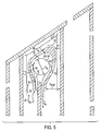
- the second guided-flow region 30 will now be described in detail. As seen with in Figures 3 and 5, the second guided-flow region 30 extends between the outer surface 96 of the contoured boundary member 32 and the first, second, and third boundary surfaces 58,60,62 of the interior cavity 18. The relative spacing between the boundary surfaces 58,60,62 and the adjacent portion of the contoured boundary member outer surface 96 varies with position along the second guided-flow region 30.
- the second guided-flow region 30 comprises a first leg 98, a second leg 100, and a third leg 102; the legs are in fluid communication.
- the first leg or section 98 spans flow-wise between the contoured boundary member first lip 82 and a first cavity tip end corner 86.
- the second leg or section 100 spans flow-wise between the first cavity tip end corner 86 and a second cavity tip end comer 88.
- the third leg or section 102 spans flow-wise between the second cavity tip end corner 88 and the contoured boundary member second lip 84.
- the distance D sgf between the contoured boundary member outer surface 96 and associated cavity boundary surface 58,60,62 varies with position along the second guided-flow region 30 and is strategically selected to impart desired flow characteristics to the second portion of cooling fluid 52 at key locations of the component 10.
- the second guided-flow region 30 is relatively-narrow near the cavity tip end corners 86,88, while remaining relatively broad near the first lip 82 and second lip 84.
- the second portion of cooling fluid 52 accelerates as it travels along the first leg 98 toward the first cavity tip corner 86, changes direction and continues accelerating along the second leg 100 toward the second cavity tip corner 88, changes direction once again and continues with decreasing velocity along the third leg 102 to head toward the second channel 36.
- the second portion of cooling fluid 52 provides impingement cooling of the cavity tip corners 86,88, as well as internal cooling of tip wall 14. It is noted that the acceleration and directional changes produces along this second guided-flow region 30 enhance the heat dissipation capabilities of the second portion of cooling fluid. It is also noted that turbulence-increasing structures 104, often referred to as "trip strips" or turbulators, may be used to further augment the heat transfer properties of cooling fluid if desired.
- cooling fluid 20 travels from a cooling fluid source, such as a compressor 106 (shown in Figure 1), pump or other suitable source, and enters the component interior cavity 18 via at least one cavity inlet 40.
- the cooling fluid 18 enters the first channel 34 and begins to travel along the cooling fluid flowpath 46 described above.
- cooling fluid 20 travelling within the first channel 34 enters the first turning zone 48 and encounters the contoured boundary member first lip 82, which splits the cooling fluid 20 into a first portion 50 and a second portion 52.
- each portion 50,52 of cooling fluid is different and strategically selected to provide appropriate cooling to the guided-flow regions 28,30.
- the first portion 50 of cooling fluid travels into the first guided-flow region 28, and the second portion travels into the second guided-flow region 30.
- the first guided-flow region 28 cools the region adjacent the first partition member free end 38, while the second guided-flow region 30 cools the cavity tip corners 86,88 and the tip wall 14.
- the exit region 80 of the first guided-flow path advantageously cooperates with the third leg 102 of the second guided-flow path 30 to ensure that flow separation tendencies are reduced as the first and second portions 50,52 of cooling fluid rejoin when leaving the first turning zone 48 to enter the second channel 36 and continue through the downstream remainder of the flowpath 26.
- the cooling fluid 20 exits the component cavity 18 through a cavity outlet 42.
- volume V 1 of the first portion 50 of cooling fluid flowing through the first guided-flow region 28 and the volume V 2 of the second portion 52 of cooling fluid flowing through the second guided-flow region 30 need not be equal.
- One particularly-effective ratio of V 2 to V 1 is within the range of about one to about four; that is, where volumetric flow in the second guided flow region 30 is up to about four times as much as the volumetric flow in the first guided flow region 28.
- the cross sectional areas of the various regions have particularly-effective relationships in the present embodiment. For example, the ratio of cross-sectional area at the first cavity tip end corner 86 to the cross-sectional area at the beginning of the first guided-flow region 30 is within the range of about 0.65 to about 0.45.
- the ratio of cross-sectional area at the second cavity tip end corner 88 to the cross-sectional area at the end of the first guided-flow region 30 is within the range of about 0.65 to about 0.45.
- the ratio of cross-sectional area within the second guided flow region second leg 100 to the cross-sectional area at the first cavity tip end corner 86 is within the range of about 0.65 to about 0.80.
Landscapes
- Engineering & Computer Science (AREA)
- Mechanical Engineering (AREA)
- General Engineering & Computer Science (AREA)
- Turbine Rotor Nozzle Sealing (AREA)
Abstract
Description
- This invention relates generally to the field of internal to combustion engines and, more particularly, to a flow guide component that produces increased cooling effectiveness without producing reduced engine efficiency.
- Combustion engines are machines that convert chemical energy stored in fuel into mechanical energy useful for generating electricity, producing thrust, or otherwise doing work. These engines typically include several cooperative sections that contribute in some way to the energy conversion process. In gas turbine engines, air discharged from a compressor section and fuel introduced from a fuel supply are mixed together and burned in a combustion section. The products of combustion are harnessed and directed through a turbine section, where they expand and turn a central rotor shaft. The rotor shaft may, in turn, be linked to devices such as an electric generator to produce electricity.
- To increase efficiency, engines are typically operated near the operational limits of the engine components. For example, to maximize the amount of energy available for conversion into electricity, the products of combustion (also referred to as the working gas or working fluid) often exit the combustion section at high temperature. This elevated temperature generates a large amount of potential energy, but it also places a great deal of stress on the downstream fluid guide components, such as the blades and vanes of the turbine section.
- In an effort to help components within the engine withstand these temperatures, a number of strategies have been developed. One strategy is to manufacture these components from advanced materials that can operate in high-temperature environments for extended periods. Another strategy includes protecting the components with special, heat-resistant coatings that lessen the effects of exposure to elevated temperatures. In still another strategy, the components may be cooled through a variety of methods. Each of these strategies has advantages and disadvantages, and the strategies may be combined to fit various situations and operating conditions.
- In situations where turbine components are cooled, one cooling method involves delivering compressor-discharge air, or other relatively-cool fluid, to the exterior of the components. The cooling fluid may flow along the surface of the component, as in "film" cooling, or it may be guided to impinge upon the component surface. Cooling fluid may also be delivered to the interior of a component so that the component temperature may be reduced from the inside out.
- Although cooling may be used to improve the high-temperature operation of blades and vanes, problems associated with this strategy limit its effectiveness in many situations. In situations where the cooling fluid is air provided by the compressor, extensive use of cooling may adversely affect engine performance by reducing the amount of air available for combustion and reducing power generating capacity of a given engine. Even in situations where cooling fluid is not provided by the compressor, it is difficult to ensure that all components are cooled sufficiently. Inadequate cooling can be troublesome, because in cases where portions of a component are not cooled sufficiently, the component may fail during operation.
- While a variety of strategies have been developed to improve the high-temperature tolerance of turbine engine components, there are difficulties associated with these strategies. Additionally, as performance requirements increase, turbine components are subjected to even-more-extreme conditions. Accordingly, there remains a need in this field for strategies that allow turbine engine components to withstand extreme temperatures.
- The present invention is a turbine engine flow guide component that provides improved tolerance to extreme operating temperatures. The guide component includes features that allow highly-efficient cooling and increased heat dissipation properties. The component includes an elongated body having an interior cavity that includes cooling fluid flowpath. First and second guided-flow regions in the flowpath are separated by a contoured boundary member. The first guided-flow region is substantially surrounded by the boundary member and adapted to produce a vortex of cooling fluid. The second guided-flow region is disposed between an end of the cavity and an outer surface of the boundary member. The first guided-flow region is adapted to cool a region surrounded by the boundary member, and the guided-flow region is adapted to cool the region disposed between the cavity and outer surface of the boundary member, thereby ensuring effective cooling of the component without requiring increased cooling flow volume or producing overcooled areas.
- Other advantages of this invention will become apparent from the following description taken in conjunction with the accompanying drawings wherein are set forth, by way of illustration and example, certain embodiments of this invention. The drawings constitute part of this specification and include exemplary embodiments of the present invention and illustrate various objects and features thereof.
-
- Fig. 1 is a side plan view of an engine using the fluid guide component of the present invention;
- Fig. 2 is a cross-section end view of the fluid guide component shown in Fig. 1, taken along cutting plane II-II' therein;
- Fig. 3 is close up view of the image shown in Fig. 2
- Fig. 4 is partial isometric view of the fluid guide component of the present invention; and
- Fig. 5 is an alternate close up view of the image shown in Fig. 2, showing fluid flow.
-
- Reference is made to the Figures, generally, in which a
fluid guide component 10 according to the present invention is shown. By way of overview, theguide component 10 includes elements that allow the component to provide enhanced temperature reduction without reducing engine performance. In one aspect of the invention, thefluid guide component 10 includes aninterior cavity 18 having features that increase heat dissipation without relying on an increased volume of cooling fluid flow. In another aspect of the invention, theguide component 10 includes guided-flow regions cooling fluid 20 through thecomponent interior cavity 18, thereby ensuring key areas of thecomponent 10 are cooled appropriately. In yet another aspect of the invention, thefluid guide component 10 includes structure that ensures effective cooling of an interiorcavity turning zone 48 without producing overcooled regions within the component. - With particular reference to Figures 1 and 2, a first embodiment of a
fluid guide component 10 of the present invention will now be discussed. In this embodiment, thecomponent 10 is an internally-cooled turbine blade for use in acombustion engine 12. Accordingly, thecomponent 10 is characterized by anattachment end 44 spaced apart from an oppositeblade tip end 54 by an elongated body portion 16. The elongated body portion 16 has an airfoil-shaped cross section with a leadingedge 66 spaced apart from an oppositetrailing edge 68 by substantially-continuous, opposingsidewalls guide component 10 need not be a blade; other embodiments, including stationary vanes or other internally-cooled, fluid-directing elements may also be used and are contemplated by this invention. - With continued reference to Figure 2, and with additional reference to Figure 4, the body portion 16 of the
fluid guide component 10 has aninterior cavity 18 withpartition members partition members body portion sidewalls boundary surfaces interior cavity 18 to define acooling fluid flowpath 26 characterized by threechannels second turning zones interior cavity 18 near thetip end 54 andattachment end 44, respectively, each fluidly link an associatedpair cooling fluid 20 is directed through theflowpath 26 to remove heat from thecomponent 10. At least onecooling fluid inlet 40 allowscooling fluid 20 to enter theinterior cavity 18, andcooling fluid outlets 42 allow the cooling fluid to exit. Although Figure 2 shows theattachment end 44 of theblade 10 as the cooling fluid inlet 40 location,cooling fluid 20 may enter theinterior cavity 18 from other locations if desired. - With reference to Figures 2 and 3, the
first turning zone 48 will now be described. As noted above, the first andsecond channels first turning zone 48, and acontoured boundary member 32 divides the first turning zone into two guided-flow regions flow regions first turning zone 48 is cooled appropriately. More particularly, as seen with reference to Figures 3 and 5, eachregion portion first portion 50 ofcooling fluid 20 flows through the first guided-flow region 28 to reduce the temperature of the area adjacent the first partition memberfree end 38, and asecond portion 52 of cooling fluid flows through the second guided-flow region 30 to reduce the temperature of the area between thecontoured boundary member 32 and thecavity boundary surfaces tip end 54 of thecomponent 10. As will be described more fully below, this dual guided-flow region arrangement advantageously ensures that thetip end 54 of thefluid guide component 10 is cooled as needed, without producing overcooled regions. - Now, with particular reference to Figures 3 and 4, a first embodiment of the
contoured boundary member 32 will be described in detail. In this embodiment, the contouredboundary member 32 is an elongated component that extends between the body portion sidewalls 70,72. With continued reference to Figure 4, the contouredboundary member 32 is a substantially-tubular structure with a cross section that resembles a horseshoe, including a roundedhead portion 74 and atapered shoulder portion 76. Thehead portion 74 provides a swirl-inducingregion 94 which has a substantially-circular cross section characterized by a defining dimension Dsi; theshoulder portion 76 defines a longitudinally-extendingflowthrough passageway 46 characterized by afirst lip 82 disposed within thefirst channel 34 and asecond lip 84 disposed within thesecond channel 36. - As seen in Figures 3, 4 and 5, the
first partition member 22 divides theflowthrough passageway 46 into anentrance region 49 and anexit region 80. The shoulder regionfirst lip 82 andfirst partition member 22 are spaced apart by a distance Di, and the shoulder regionsecond lip 84 is spaced apart from the first partition member by a distance of De. It is also noted that the first partition memberfree end 54 need not be centered within the flowthrough passage 46: the values of Di need not be equal De. In this embodiment, the ratio of Di to De is about two. Theentrance region 49 provides a metering slot through which thefirst portion 50 of cooling fluid enters thehead portion 74, and the exit region allows cooling fluid to travel out of the head region and into thesecond channel 36, downstream of thefirst turning zone 48. The entrance andexit regions region 94 form the first guided-flow region 28. These threeregions fluid 50 within the swirl-inducing region that advantageously cools the region adjacent the first partition memberfree end 38. It is noted that the vortex flow pattern produced in the swirl-inducingregion 94 increases the heat dissipation properties for thefirst portion 50 of cooling fluid passing adjacent the first partition memberfree end 38. - With continued reference to Figure 3, and with additional reference to Figures 4 and 5, as the first the
first lip 82 and first partitionfree end 38 cooperatively direct thefirst portion 50 of cooling fluid along a path which is substantially-tangential to the vortex maintained by the contoured boundaries of the swirl-inducingregion 94. The interaction of fluid passing leaving thefluid entrance region 49 and entering the swirl-inducingregion 94 creates a jet and contributes to the vortex flow established in the swirl-inducing region. Although the dimensions Dsi and Di may be scaled to accommodatefluid guide components 10 of various sizes, it is preferable that the ratio of Dsi to Dl be within the range of about 10 to about 15. It is noted that while described as resembling a horseshoe, the contouredboundary member 32 may have a variety of cross-section profiles, including substantially C-shaped or U-shaped; essentially any cross section which forms a vortex or induces swirled flow within the first guided-flow region effective to reduce the temperature of the area adjacent the first partition memberfree end 38 would suffice and is contemplated by the present invention. - The second guided-
flow region 30 will now be described in detail. As seen with in Figures 3 and 5, the second guided-flow region 30 extends between theouter surface 96 of the contouredboundary member 32 and the first, second, and third boundary surfaces 58,60,62 of theinterior cavity 18. The relative spacing between the boundary surfaces 58,60,62 and the adjacent portion of the contoured boundary memberouter surface 96 varies with position along the second guided-flow region 30. The second guided-flow region 30 comprises afirst leg 98, asecond leg 100, and athird leg 102; the legs are in fluid communication. - With cooperative reference to Figures 3 and 5, the first leg or
section 98 spans flow-wise between the contoured boundary memberfirst lip 82 and a first cavitytip end corner 86. The second leg orsection 100 spans flow-wise between the first cavitytip end corner 86 and a second cavity tip end comer 88. The third leg orsection 102 spans flow-wise between the second cavity tip end corner 88 and the contoured boundary membersecond lip 84. As noted above, The distance Dsgf between the contoured boundary memberouter surface 96 and associatedcavity boundary surface flow region 30 and is strategically selected to impart desired flow characteristics to the second portion of coolingfluid 52 at key locations of thecomponent 10. For example, the second guided-flow region 30 is relatively-narrow near the cavitytip end corners 86,88, while remaining relatively broad near thefirst lip 82 andsecond lip 84. - With this arrangement, the second portion of cooling
fluid 52 accelerates as it travels along thefirst leg 98 toward the firstcavity tip corner 86, changes direction and continues accelerating along thesecond leg 100 toward the second cavity tip corner 88, changes direction once again and continues with decreasing velocity along thethird leg 102 to head toward thesecond channel 36. In keeping with various aspects of the present invention, the second portion of coolingfluid 52 provides impingement cooling of thecavity tip corners 86,88, as well as internal cooling oftip wall 14. It is noted that the acceleration and directional changes produces along this second guided-flow region 30 enhance the heat dissipation capabilities of the second portion of cooling fluid. It is also noted that turbulence-increasingstructures 104, often referred to as "trip strips" or turbulators, may be used to further augment the heat transfer properties of cooling fluid if desired. - During operation of an
engine 12 in which the fluid guide component of the present invention is installed, coolingfluid 20 travels from a cooling fluid source, such as a compressor 106 (shown in Figure 1), pump or other suitable source, and enters the componentinterior cavity 18 via at least onecavity inlet 40. The coolingfluid 18 enters thefirst channel 34 and begins to travel along the coolingfluid flowpath 46 described above. With continued operation, coolingfluid 20 travelling within thefirst channel 34 enters thefirst turning zone 48 and encounters the contoured boundary memberfirst lip 82, which splits the coolingfluid 20 into afirst portion 50 and asecond portion 52. - The behavior, path, and purpose of each
portion flow regions first portion 50 of cooling fluid travels into the first guided-flow region 28, and the second portion travels into the second guided-flow region 30. As noted above, the first guided-flow region 28 cools the region adjacent the first partition memberfree end 38, while the second guided-flow region 30 cools thecavity tip corners 86,88 and thetip wall 14. Additionally, theexit region 80 of the first guided-flow path advantageously cooperates with thethird leg 102 of the second guided-flow path 30 to ensure that flow separation tendencies are reduced as the first andsecond portions first turning zone 48 to enter thesecond channel 36 and continue through the downstream remainder of theflowpath 26. After travelling through the coolingfluid flowpath 26, the coolingfluid 20 exits thecomponent cavity 18 through acavity outlet 42. With this arrangement, coolingfluid 20 travelling through within the internal cavity strategically cools thefirst turning zone 48 without an increased amount of cooling fluid volume or producing overcooled locations. - It is noted that the volume V1 of the
first portion 50 of cooling fluid flowing through the first guided-flow region 28 and the volume V2 of thesecond portion 52 of cooling fluid flowing through the second guided-flow region 30 need not be equal. One particularly-effective ratio of V2 to V1 is within the range of about one to about four; that is, where volumetric flow in the second guidedflow region 30 is up to about four times as much as the volumetric flow in the first guidedflow region 28. It is also noted the cross sectional areas of the various regions have particularly-effective relationships in the present embodiment. For example, the ratio of cross-sectional area at the first cavitytip end corner 86 to the cross-sectional area at the beginning of the first guided-flow region 30 is within the range of about 0.65 to about 0.45. The ratio of cross-sectional area at the second cavity tip end corner 88 to the cross-sectional area at the end of the first guided-flow region 30 is within the range of about 0.65 to about 0.45. The ratio of cross-sectional area within the second guided flow regionsecond leg 100 to the cross-sectional area at the first cavitytip end corner 86 is within the range of about 0.65 to about 0.80. - It is to be understood that while certain forms of the invention have been illustrated and described, it is not to be limited to the specific forms or arrangement of parts herein described and shown. It will be apparent to those skilled in the art that various, including modifications, rearrangements and substitutions, may be made without departing from the scope of this invention and the invention is not to be considered limited to what is shown in the drawings and described in the specification. The scope if the invention is defined by the claims appended hereto.
Claims (20)
- An internally-cooled fluid directing component comprising:wherein said first channel, said turning zone, and second channel cooperatively form a flowthrough path adapted to transmit cooling fluid between said cooling fluid inlet and said cooling fluid outlet,an elongated body member having a first end and a second end;an interior cavity disposed within said body member, said interior cavity having a cooling fluid inlet and a cooling fluid outlet;a partition member disposed within said interior cavity and positioned to divide said interior cavity into a first channel and a second channel;a turning zone disposed within interior cavity and fluidly linking said first and second channels;at least one boundary member disposed within said turning zone, said at least one boundary member dividing said turning zone into a first guided-flow region and a second guided-flow region;
whereby said first and second guided-flow regions are adapted to direct a first portion of cooling fluid through said first guided-flow region and a second portion of cooling fluid through said second guided-flow regions, respectively, thereby allowing strategic cooling of said turning zone. - The internally-cooled fluid directing component of Claim 1, wherein said first guided-flow region is proximate a first end of said partition member and said second guided-flow region is proximate a tip wall of said interior cavity.
- The internally-cooled fluid directing component of Claim 1, wherein said boundary member is contoured to substantially surround said first guided-flow region.
- internally-cooled fluid directing component of Claim 3, wherein said first guided-flow region includes a swirl-inducing region defined by said contoured boundary member.
- The internally-cooled fluid directing component of Claim 4, wherein said swirl-inducing region is fluidly connected to said first channel by an entrance region and an exit region, said entrance region and said exit region, and said swirl-inducing region being sized and shaped to cooperatively direct said first portion of cooling fluid along a vortex-shaped flowpath.
- The internally-cooled fluid directing component of Claim 5, wherein said entrance region and exit region are spaced apart by said partition member.
- The internally-cooled fluid directing component of Claim 5, wherein said first guided-flow region is adapted to flow fluid a first flow rate and said second guided-flow region is adapted to flow fluid at a second flow rate, wherein the ratio of said first flow rate to said second flow rate is within the range of about 1 to about 4.
- The internally-cooled fluid directing component of Claim 5, wherein said entrance region is characterized by a first distance, and wherein swirl-inducing region is characterized by a second distance, and wherein the ratio of said second distance to said first distance is within the range of about 10 to about 15.
- The internally-cooled fluid directing component of Claim 3, wherein said first guided-flow region is proximate a first end of said partition member and said second guided-flow region is proximate a tip wall of said interior cavity.
- The internally-cooled fluid directing component of Claim 9, wherein second guided-flow region is disposed between said boundary member and said interior cavity.
- The internally-cooled fluid directing component of Claim 9, wherein second guided-flow region includes at least one tapered region adapted to provide accelerated flow adjacent a corner of said interior cavity.
- The internally-cooled fluid directing component of Claim 11, wherein second guided-flow region includes turbulence increasing elements.
- The internally-cooled fluid directing component of Claim 1, wherein second guided-flow region further includes at least one tapered region adapted to provide accelerated flow adjacent a corner of said cavity
- The internally-cooled fluid directing component of Claim 1, wherein said body member is characterized by an airfoil-shaped cross section including a leading edge spaced apart from a trailing edge by a first sidewall and an opposite second sidewall.
- The internally-cooled fluid directing component of Claim 1, wherein said boundary member extends flow-wise within said turning zone.
- An internally-cooled fluid directing component, comprising:an elongated body having an interior cavity disposed therein, said interior cavity including a cooling fluid flowpath;a first guided-flow region disposed within said flowpath and a second guided-flow region disposed within said flowpath, said guided-flow regions being separated by a contoured boundary member disposed therebetween;said first guided-flow region being substantially surrounded by said boundary member, and said second guided-flow region being disposed between an end of said cavity and an outer surface of said boundary member;said first guided-flow region being adapted to produce a vortex,whereby said first guided-flow region is adapted to cool a region surrounded by said boundary member, and said second guided-flow region is adapted to cool a region disposed between an end of said cavity and an outer surface of said boundary member.
- The internally-cooled fluid directing component of Claim 16, further including a partition member in said interior cavity to form a first channel and a second channel, said first and second channels being fluidly linked via a turning zone disposed proximate an end of said interior cavity, said channels and said turning zone being disposed within said flowpath.
- The internally-cooled fluid directing component of Claim 17, wherein said boundary member in said turning zone and said first guided-flow region and a second guided-flow region comprise said turning zone.
- A method of internally cooling a guide member comprising the steps of:providing an internally-cooled fluid guide component having an elongated body with an interior cavity disposed therein, said interior cavity including a cooling fluid inlet and a cooling fluid outlet, said cooling fluid inlets and outlet being fluidly linked by a flowpath extending therebetween;disposing a partition member in said interior cavity to form a first channel and a second channel, said first and second channels being fluidly linked via a turning zone disposed proximate an end of said interior cavity, said channels and said turning zone being disposed within said flowpath;disposing a boundary member in said turning zone, said boundary member dividing said turning zone into a first guided-flow region and a second guided-flow region,attaching a source of cooling fluid to said cooling fluid inlet;flowing cooling fluid through said cooling fluid inlet to said exit through said flowpath, whereby cooling fluid flowing through said first guided region cools a region proximate said partition member and cooling fluid flowing through said second guided flow region cools a region disposed between said boundary member and said end of said cavity.
- A method of internally cooling a guide member wherein said first guided flow region includes a swirl-inducing region adapted to produce a vortex of cooling fluid within said first guided-flow region.
Applications Claiming Priority (2)
| Application Number | Priority Date | Filing Date | Title |
|---|---|---|---|
| US10/671,249 US6939102B2 (en) | 2003-09-25 | 2003-09-25 | Flow guide component with enhanced cooling |
| US671249 | 2003-09-25 |
Publications (2)
| Publication Number | Publication Date |
|---|---|
| EP1519008A1 true EP1519008A1 (en) | 2005-03-30 |
| EP1519008B1 EP1519008B1 (en) | 2010-03-03 |
Family
ID=34194842
Family Applications (1)
| Application Number | Title | Priority Date | Filing Date |
|---|---|---|---|
| EP04077522A Expired - Lifetime EP1519008B1 (en) | 2003-09-25 | 2004-09-14 | Internally cooled fluid directing component |
Country Status (3)
| Country | Link |
|---|---|
| US (1) | US6939102B2 (en) |
| EP (1) | EP1519008B1 (en) |
| DE (1) | DE602004025775D1 (en) |
Cited By (1)
| Publication number | Priority date | Publication date | Assignee | Title |
|---|---|---|---|---|
| WO2016148690A1 (en) * | 2015-03-17 | 2016-09-22 | Siemens Energy, Inc. | Turbine blade with a non-constraint flow turning guide structure |
Families Citing this family (28)
| Publication number | Priority date | Publication date | Assignee | Title |
|---|---|---|---|---|
| US7137782B2 (en) * | 2004-04-27 | 2006-11-21 | General Electric Company | Turbulator on the underside of a turbine blade tip turn and related method |
| US8465252B2 (en) * | 2009-04-17 | 2013-06-18 | United Technologies Corporation | Turbine engine rotating cavity anti-vortex cascade |
| US8177503B2 (en) * | 2009-04-17 | 2012-05-15 | United Technologies Corporation | Turbine engine rotating cavity anti-vortex cascade |
| US8562286B2 (en) * | 2010-04-06 | 2013-10-22 | United Technologies Corporation | Dead ended bulbed rib geometry for a gas turbine engine |
| US9145780B2 (en) * | 2011-12-15 | 2015-09-29 | United Technologies Corporation | Gas turbine engine airfoil cooling circuit |
| US8864467B1 (en) | 2012-01-26 | 2014-10-21 | Florida Turbine Technologies, Inc. | Turbine blade with serpentine flow cooling |
| US8985940B2 (en) * | 2012-03-30 | 2015-03-24 | Solar Turbines Incorporated | Turbine cooling apparatus |
| US20140219813A1 (en) * | 2012-09-14 | 2014-08-07 | Rafael A. Perez | Gas turbine engine serpentine cooling passage |
| US9995148B2 (en) | 2012-10-04 | 2018-06-12 | General Electric Company | Method and apparatus for cooling gas turbine and rotor blades |
| US9850762B2 (en) | 2013-03-13 | 2017-12-26 | General Electric Company | Dust mitigation for turbine blade tip turns |
| US9797258B2 (en) * | 2013-10-23 | 2017-10-24 | General Electric Company | Turbine bucket including cooling passage with turn |
| EP3149279A1 (en) | 2014-05-29 | 2017-04-05 | General Electric Company | Fastback turbulator |
| CA2949539A1 (en) | 2014-05-29 | 2016-02-18 | General Electric Company | Engine components with impingement cooling features |
| US10364684B2 (en) | 2014-05-29 | 2019-07-30 | General Electric Company | Fastback vorticor pin |
| US10422235B2 (en) | 2014-05-29 | 2019-09-24 | General Electric Company | Angled impingement inserts with cooling features |
| US9957816B2 (en) | 2014-05-29 | 2018-05-01 | General Electric Company | Angled impingement insert |
| US10233775B2 (en) | 2014-10-31 | 2019-03-19 | General Electric Company | Engine component for a gas turbine engine |
| US10280785B2 (en) | 2014-10-31 | 2019-05-07 | General Electric Company | Shroud assembly for a turbine engine |
| DE102015112643A1 (en) * | 2015-07-31 | 2017-02-02 | Wobben Properties Gmbh | Wind turbine rotor blade |
| US10012092B2 (en) * | 2015-08-12 | 2018-07-03 | United Technologies Corporation | Low turn loss baffle flow diverter |
| US10184341B2 (en) | 2015-08-12 | 2019-01-22 | United Technologies Corporation | Airfoil baffle with wedge region |
| US10450874B2 (en) | 2016-02-13 | 2019-10-22 | General Electric Company | Airfoil for a gas turbine engine |
| US10544684B2 (en) | 2016-06-29 | 2020-01-28 | General Electric Company | Interior cooling configurations for turbine rotor blades |
| US10774657B2 (en) | 2018-11-23 | 2020-09-15 | Raytheon Technologies Corporation | Baffle assembly for gas turbine engine components |
| KR102161765B1 (en) * | 2019-02-22 | 2020-10-05 | 두산중공업 주식회사 | Airfoil for turbine, turbine including the same |
| JP7234006B2 (en) | 2019-03-29 | 2023-03-07 | 三菱重工業株式会社 | High temperature parts and method for manufacturing high temperature parts |
| DE102019125779B4 (en) * | 2019-09-25 | 2024-03-21 | Man Energy Solutions Se | Blade of a turbomachine |
| EP3862537A1 (en) * | 2020-02-10 | 2021-08-11 | General Electric Company Polska sp. z o.o. | Cooled turbine nozzle and nozzle segment |
Citations (7)
| Publication number | Priority date | Publication date | Assignee | Title |
|---|---|---|---|---|
| US4474532A (en) * | 1981-12-28 | 1984-10-02 | United Technologies Corporation | Coolable airfoil for a rotary machine |
| US5403159A (en) * | 1992-11-30 | 1995-04-04 | United Technoligies Corporation | Coolable airfoil structure |
| US5669759A (en) * | 1995-02-03 | 1997-09-23 | United Technologies Corporation | Turbine airfoil with enhanced cooling |
| EP1010859A2 (en) * | 1998-12-18 | 2000-06-21 | General Electric Company | Turbine airfoil and methods for airfoil cooling |
| US6257830B1 (en) * | 1997-06-06 | 2001-07-10 | Mitsubishi Heavy Industries, Ltd. | Gas turbine blade |
| US6439848B2 (en) * | 1999-12-24 | 2002-08-27 | Alstom (Switzerland) Ltd | Drilled cooling air openings in gas turbine components |
| US6595750B2 (en) * | 2000-12-16 | 2003-07-22 | Alstom Power N.V. | Component of a flow machine |
Family Cites Families (5)
| Publication number | Priority date | Publication date | Assignee | Title |
|---|---|---|---|---|
| US4278400A (en) * | 1978-09-05 | 1981-07-14 | United Technologies Corporation | Coolable rotor blade |
| US4775296A (en) * | 1981-12-28 | 1988-10-04 | United Technologies Corporation | Coolable airfoil for a rotary machine |
| GB2165315B (en) * | 1984-10-04 | 1987-12-31 | Rolls Royce | Improvements in or relating to hollow fluid cooled turbine blades |
| US5536143A (en) * | 1995-03-31 | 1996-07-16 | General Electric Co. | Closed circuit steam cooled bucket |
| DE19921644B4 (en) * | 1999-05-10 | 2012-01-05 | Alstom | Coolable blade for a gas turbine |
-
2003
- 2003-09-25 US US10/671,249 patent/US6939102B2/en not_active Expired - Lifetime
-
2004
- 2004-09-14 DE DE602004025775T patent/DE602004025775D1/en not_active Expired - Lifetime
- 2004-09-14 EP EP04077522A patent/EP1519008B1/en not_active Expired - Lifetime
Patent Citations (7)
| Publication number | Priority date | Publication date | Assignee | Title |
|---|---|---|---|---|
| US4474532A (en) * | 1981-12-28 | 1984-10-02 | United Technologies Corporation | Coolable airfoil for a rotary machine |
| US5403159A (en) * | 1992-11-30 | 1995-04-04 | United Technoligies Corporation | Coolable airfoil structure |
| US5669759A (en) * | 1995-02-03 | 1997-09-23 | United Technologies Corporation | Turbine airfoil with enhanced cooling |
| US6257830B1 (en) * | 1997-06-06 | 2001-07-10 | Mitsubishi Heavy Industries, Ltd. | Gas turbine blade |
| EP1010859A2 (en) * | 1998-12-18 | 2000-06-21 | General Electric Company | Turbine airfoil and methods for airfoil cooling |
| US6439848B2 (en) * | 1999-12-24 | 2002-08-27 | Alstom (Switzerland) Ltd | Drilled cooling air openings in gas turbine components |
| US6595750B2 (en) * | 2000-12-16 | 2003-07-22 | Alstom Power N.V. | Component of a flow machine |
Cited By (3)
| Publication number | Priority date | Publication date | Assignee | Title |
|---|---|---|---|---|
| WO2016148690A1 (en) * | 2015-03-17 | 2016-09-22 | Siemens Energy, Inc. | Turbine blade with a non-constraint flow turning guide structure |
| JP2018512535A (en) * | 2015-03-17 | 2018-05-17 | シーメンス エナジー インコーポレイテッド | Turbine blade with unconstrained flow diverting guide structure |
| US10196906B2 (en) | 2015-03-17 | 2019-02-05 | Siemens Energy, Inc. | Turbine blade with a non-constraint flow turning guide structure |
Also Published As
| Publication number | Publication date |
|---|---|
| DE602004025775D1 (en) | 2010-04-15 |
| US6939102B2 (en) | 2005-09-06 |
| US20050069414A1 (en) | 2005-03-31 |
| EP1519008B1 (en) | 2010-03-03 |
Similar Documents
| Publication | Publication Date | Title |
|---|---|---|
| US6939102B2 (en) | Flow guide component with enhanced cooling | |
| EP1001137B1 (en) | Gas turbine airfoil with axial serpentine cooling circuits | |
| US5498133A (en) | Pressure regulated film cooling | |
| EP2204538B1 (en) | Turbine blade cooling circuits | |
| JP4063937B2 (en) | Turbulence promoting structure of cooling passage of blade in gas turbine engine | |
| US8083485B2 (en) | Angled tripped airfoil peanut cavity | |
| EP2491230B1 (en) | Gas turbine engine comprising a turbine airfoil with tapered cooling passageways | |
| US8262355B2 (en) | Cooled component | |
| US6607355B2 (en) | Turbine airfoil with enhanced heat transfer | |
| US6398486B1 (en) | Steam exit flow design for aft cavities of an airfoil | |
| US6290463B1 (en) | Slotted impingement cooling of airfoil leading edge | |
| US8096769B2 (en) | Damper | |
| EP3205832B1 (en) | Blade outer air seal with chevron trip strip | |
| US8043059B1 (en) | Turbine blade with multi-vortex tip cooling and sealing | |
| JPH0681675A (en) | Gas turbine and stage device therefor | |
| US20050281667A1 (en) | Cooled gas turbine vane | |
| EP2878767A1 (en) | Turbine endwall with micro-circuit cooling | |
| CA2462986A1 (en) | Method and apparatus for cooling an airfoil | |
| US20170167268A1 (en) | Engine component with film cooling | |
| EP2947273B1 (en) | Airfoil and corresponding method of cooling an airfoil | |
| US10830060B2 (en) | Engine component with flow enhancer | |
| WO2017171764A1 (en) | Turbine airfoil with internal cooling channels having flow splitter feature | |
| EP3287599B1 (en) | Gas turbine blade | |
| CN113250758B (en) | Turbine nozzle segment and turbine nozzle comprising such a turbine nozzle segment | |
| KR102924670B1 (en) | Gas turbine stator and gas turbine |
Legal Events
| Date | Code | Title | Description |
|---|---|---|---|
| PUAI | Public reference made under article 153(3) epc to a published international application that has entered the european phase |
Free format text: ORIGINAL CODE: 0009012 |
|
| AK | Designated contracting states |
Kind code of ref document: A1 Designated state(s): AT BE BG CH CY CZ DE DK EE ES FI FR GB GR HU IE IT LI LU MC NL PL PT RO SE SI SK TR |
|
| AX | Request for extension of the european patent |
Extension state: AL HR LT LV MK |
|
| 17P | Request for examination filed |
Effective date: 20050802 |
|
| RAP1 | Party data changed (applicant data changed or rights of an application transferred) |
Owner name: SIEMENS POWER GENERATION, INC. |
|
| AKX | Designation fees paid |
Designated state(s): DE FR GB IT |
|
| 17Q | First examination report despatched |
Effective date: 20051024 |
|
| RAP1 | Party data changed (applicant data changed or rights of an application transferred) |
Owner name: SIEMENS ENERGY, INC. |
|
| GRAP | Despatch of communication of intention to grant a patent |
Free format text: ORIGINAL CODE: EPIDOSNIGR1 |
|
| RTI1 | Title (correction) |
Free format text: INTERNALLY COOLED FLUID DIRECTING COMPONENT |
|
| GRAS | Grant fee paid |
Free format text: ORIGINAL CODE: EPIDOSNIGR3 |
|
| GRAA | (expected) grant |
Free format text: ORIGINAL CODE: 0009210 |
|
| AK | Designated contracting states |
Kind code of ref document: B1 Designated state(s): DE FR GB IT |
|
| REG | Reference to a national code |
Ref country code: GB Ref legal event code: FG4D |
|
| REF | Corresponds to: |
Ref document number: 602004025775 Country of ref document: DE Date of ref document: 20100415 Kind code of ref document: P |
|
| PLBE | No opposition filed within time limit |
Free format text: ORIGINAL CODE: 0009261 |
|
| STAA | Information on the status of an ep patent application or granted ep patent |
Free format text: STATUS: NO OPPOSITION FILED WITHIN TIME LIMIT |
|
| 26N | No opposition filed |
Effective date: 20101206 |
|
| REG | Reference to a national code |
Ref country code: FR Ref legal event code: PLFP Year of fee payment: 13 |
|
| REG | Reference to a national code |
Ref country code: FR Ref legal event code: PLFP Year of fee payment: 14 |
|
| REG | Reference to a national code |
Ref country code: FR Ref legal event code: PLFP Year of fee payment: 15 |
|
| PGFP | Annual fee paid to national office [announced via postgrant information from national office to epo] |
Ref country code: FR Payment date: 20180924 Year of fee payment: 15 Ref country code: IT Payment date: 20180926 Year of fee payment: 15 |
|
| PGFP | Annual fee paid to national office [announced via postgrant information from national office to epo] |
Ref country code: GB Payment date: 20180911 Year of fee payment: 15 |
|
| PGFP | Annual fee paid to national office [announced via postgrant information from national office to epo] |
Ref country code: DE Payment date: 20181119 Year of fee payment: 15 |
|
| REG | Reference to a national code |
Ref country code: DE Ref legal event code: R119 Ref document number: 602004025775 Country of ref document: DE |
|
| PG25 | Lapsed in a contracting state [announced via postgrant information from national office to epo] |
Ref country code: DE Free format text: LAPSE BECAUSE OF NON-PAYMENT OF DUE FEES Effective date: 20200401 |
|
| PG25 | Lapsed in a contracting state [announced via postgrant information from national office to epo] |
Ref country code: IT Free format text: LAPSE BECAUSE OF NON-PAYMENT OF DUE FEES Effective date: 20190914 |
|
| GBPC | Gb: european patent ceased through non-payment of renewal fee |
Effective date: 20190914 |
|
| PG25 | Lapsed in a contracting state [announced via postgrant information from national office to epo] |
Ref country code: GB Free format text: LAPSE BECAUSE OF NON-PAYMENT OF DUE FEES Effective date: 20190914 Ref country code: FR Free format text: LAPSE BECAUSE OF NON-PAYMENT OF DUE FEES Effective date: 20190930 |