EP1518750A1 - Livestock transport vehicle - Google Patents
Livestock transport vehicle Download PDFInfo
- Publication number
- EP1518750A1 EP1518750A1 EP04425689A EP04425689A EP1518750A1 EP 1518750 A1 EP1518750 A1 EP 1518750A1 EP 04425689 A EP04425689 A EP 04425689A EP 04425689 A EP04425689 A EP 04425689A EP 1518750 A1 EP1518750 A1 EP 1518750A1
- Authority
- EP
- European Patent Office
- Prior art keywords
- vehicle according
- pair
- platform
- cylinders
- cylinder units
- Prior art date
- Legal status (The legal status is an assumption and is not a legal conclusion. Google has not performed a legal analysis and makes no representation as to the accuracy of the status listed.)
- Withdrawn
Links
- 244000144972 livestock Species 0.000 title claims description 6
- 238000005259 measurement Methods 0.000 description 2
- 241001465754 Metazoa Species 0.000 description 1
- 238000012790 confirmation Methods 0.000 description 1
- 230000007797 corrosion Effects 0.000 description 1
- 238000005260 corrosion Methods 0.000 description 1
- 230000000284 resting effect Effects 0.000 description 1
- 230000001360 synchronised effect Effects 0.000 description 1
- 210000002700 urine Anatomy 0.000 description 1
- 238000003466 welding Methods 0.000 description 1
Images


Classifications
-
- B—PERFORMING OPERATIONS; TRANSPORTING
- B60—VEHICLES IN GENERAL
- B60P—VEHICLES ADAPTED FOR LOAD TRANSPORTATION OR TO TRANSPORT, TO CARRY, OR TO COMPRISE SPECIAL LOADS OR OBJECTS
- B60P3/00—Vehicles adapted to transport, to carry or to comprise special loads or objects
- B60P3/04—Vehicles adapted to transport, to carry or to comprise special loads or objects for transporting animals
-
- B—PERFORMING OPERATIONS; TRANSPORTING
- B60—VEHICLES IN GENERAL
- B60P—VEHICLES ADAPTED FOR LOAD TRANSPORTATION OR TO TRANSPORT, TO CARRY, OR TO COMPRISE SPECIAL LOADS OR OBJECTS
- B60P1/00—Vehicles predominantly for transporting loads and modified to facilitate loading, consolidating the load, or unloading
- B60P1/02—Vehicles predominantly for transporting loads and modified to facilitate loading, consolidating the load, or unloading with parallel up-and-down movement of load supporting or containing element
Definitions
- the present invention relates to livestock transport vehicles, or more generally, other articles, with one or more platforms that are moveable in height inside the body.
- Livestock transport vehicles are already known, with at least one platform provided in the body, which can be positioned in height to form at least one extra loading surface, besides that of the vehicle.
- a lorry for transporting livestock comprising at least one platform inside the relative body, which can be moved in height with hydraulic cylinders, with four lateral driving means guided along guide uprights provided on the walls of the body, and wheels joined to an equal number of vertical extension chains for raising and lowering the platform.
- the guide uprights present a C section open towards the inside of the body, whilst the means for driving the platform are each made up of two L elements and spaced out to define a channel-shaped slot between them, the wheels and chains being level with said slots.
- the four hydraulic cylinders for controlling the height movements of the platform are telescopic and therefore present a considerable size, which significantly limits the internal load volume of the body.
- Cable handling systems are also used instead of hydraulic actuators, which, despite being of a reduced size compared with the telescopic cylinders, are, however, less strong and more easily subject to breaking, also due to corrosion caused by the urine of the animals.
- Such object is achieved with a vehicle, in particular, for transporting livestock, according to at least claim 1 that will follow.
- the body of a transport vehicle is globally indicated with reference numeral 11, with contrasting vertical uprights 12 extending along its lateral sides 11'.
- At least one loading platform 14 is provided in the body guided along the uprights 12, which can be moved and positioned in height above the level surface 13 of the vehicle.
- a first guide section 12' is made in each upright 12 with a C section open towards the inside of the body along which respective driving means 15 are designed to run; the driving means are provided on the sides of the platform 14 opposite the side walls of the body 11.
- Each driving means 15 is configured to join to a corresponding profile 12' and define an axial channel-shaped slot 17, in which a chain 18 extends, which is fixed and resting against a confirmation profile 18'.
- a device for synchronising the movements of the platform is applied below the platform 14.
- This device comprises two longitudinal shafts 20 mounted onto supports 19 fixed beneath the platform 14, onto which pinions 21 are keyed to join to and move along the chains 18.
- the longitudinal shafts 20 are connected by transversal shafts 22 and pairs of conical wheels 23 to guarantee synchronised rotation of all of the pinions 21, and consequently constantly parallel positioning and movement of the platform, independently of the distribution of the load on the platform.
- Pairs of single acting cylinder units 24, 25 are provided to control the height movements of the platform 14, which are operatively connected in series and cooperating with stems 24', 25' protruding from opposite directions.
- each pair of cylinder units is mounted vertically and extends at the side of a respective C guide section 12'.
- One cylinder unit therefore comprises a stem 24' facing downwards.
- the cylinders of each pair of cylinder units are arranged side by side and integral, for example by welding. Therefore, in practice, the second is also moved by operating just one of the two cylinders of a pair.
- a block 26 is constrained to the top of the stem 24' facing upwards, to which an arm 27 is suitably fixed for raising the platform.
- each pair of cylinder units 24, 25 can be contained in a second profile 12", where the driving means 15 run.
- the block 26 carrying the arm 27 is configured to run along said second guide section 12".
- the pairs of cylinder units 24, 25 contained in the uprights 12 protrude slightly from the lateral sides 11 of the vehicle towards the inside of the body, taking up an even smaller volume compared with that determined by the driving means 15.
- At least one second loading platform 28 can be fixed along the pairs of cylinder units 24,25, and guided along the uprights 12 with the above-described driving means.
- the vehicle proposed here allows an internal width of 2,42 m to be used, and so two pallets, 1,20 m each, can be transported, which is impossible in the present vehicles with hydraulically controlled platforms.
Landscapes
- Engineering & Computer Science (AREA)
- Transportation (AREA)
- Mechanical Engineering (AREA)
- Health & Medical Sciences (AREA)
- Public Health (AREA)
- Vehicle Body Suspensions (AREA)
Abstract
The present invention relates to a transport vehicle,
comprising a body inside which at least one platform (14) is
provided that can be moved in height by at least one pair
of cylinder units (24,25), which are operatively mechanically connected in
series. Each pair of cylinder units comprises cylinders
that are integral, set side by side and co-operating with
stems protruding from opposite directions. The platform
is fixed to supporting arms attached to the top of the
stems facing upwards.
Description
- The present invention relates to livestock transport vehicles, or more generally, other articles, with one or more platforms that are moveable in height inside the body.
- Livestock transport vehicles are already known, with at least one platform provided in the body, which can be positioned in height to form at least one extra loading surface, besides that of the vehicle.
- For example, in a previous patent for Industrial Invention N. 1.172.018 in the name of the same Applicant a lorry for transporting livestock is described, comprising at least one platform inside the relative body, which can be moved in height with hydraulic cylinders, with four lateral driving means guided along guide uprights provided on the walls of the body, and wheels joined to an equal number of vertical extension chains for raising and lowering the platform. The guide uprights present a C section open towards the inside of the body, whilst the means for driving the platform are each made up of two L elements and spaced out to define a channel-shaped slot between them, the wheels and chains being level with said slots.
- In these known embodiments, the four hydraulic cylinders for controlling the height movements of the platform are telescopic and therefore present a considerable size, which significantly limits the internal load volume of the body.
- Cable handling systems are also used instead of hydraulic actuators, which, despite being of a reduced size compared with the telescopic cylinders, are, however, less strong and more easily subject to breaking, also due to corrosion caused by the urine of the animals.
- It is an object of the present invention to propose a vehicle such as the one described in the above-stated patent by the same Applicant, wherein the size of the hydraulic actuators for operating the platform is greatly reduced in comparison with that of the current telescopic cylinders, thus allowing platforms with a greater surface to be mounted onto the vehicle, maintaining an elevated running height and the external measurements of the vehicle permitted by the highway code.
- Such object is achieved with a vehicle, in particular, for transporting livestock, according to at least claim 1 that will follow.
- Additional details of the invention will nonetheless be further appreciated during the course of the description that is reported below, with reference to the accompanying drawings, which are indicative and not limiting, wherein:
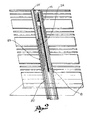
- Figure 1 shows a rear perspective view of a vehicle with two loading platforms;
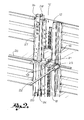
- Figure 2 shows the means for driving and operating the platform;
- Figure 2a shows an enlarged detail of these means in a perspective view;
- Figure 3 shows a view from above of an enlarged detail of the aforesaid means;
- Figure 4 shows a view from above of the only device for synchronising the movements of the platform.
- In said figures, the body of a transport vehicle is globally indicated with
reference numeral 11, with contrastingvertical uprights 12 extending along its lateral sides 11'. At least oneloading platform 14 is provided in the body guided along theuprights 12, which can be moved and positioned in height above thelevel surface 13 of the vehicle. - A first guide section 12' is made in each upright 12 with a C section open towards the inside of the body along which respective driving means 15 are designed to run; the driving means are provided on the sides of the
platform 14 opposite the side walls of thebody 11. - Each driving means 15 is configured to join to a corresponding profile 12' and define an axial channel-
shaped slot 17, in which achain 18 extends, which is fixed and resting against a confirmation profile 18'. - A device for synchronising the movements of the platform is applied below the
platform 14. This device comprises twolongitudinal shafts 20 mounted ontosupports 19 fixed beneath theplatform 14, onto whichpinions 21 are keyed to join to and move along thechains 18. Thelongitudinal shafts 20 are connected bytransversal shafts 22 and pairs ofconical wheels 23 to guarantee synchronised rotation of all of thepinions 21, and consequently constantly parallel positioning and movement of the platform, independently of the distribution of the load on the platform. - Pairs of single
acting cylinder units platform 14, which are operatively connected in series and cooperating with stems 24', 25' protruding from opposite directions. In more detail, each pair of cylinder units is mounted vertically and extends at the side of a respective C guide section 12'. One cylinder unit therefore comprises a stem 24' facing downwards. - According to a preferred embodiment of the invention, the cylinders of each pair of cylinder units are arranged side by side and integral, for example by welding. Therefore, in practice, the second is also moved by operating just one of the two cylinders of a pair.
- A
block 26 is constrained to the top of the stem 24' facing upwards, to which anarm 27 is suitably fixed for raising the platform. - Advantageously, each pair of
cylinder units second profile 12", where the driving means 15 run. In this case, theblock 26 carrying thearm 27 is configured to run along saidsecond guide section 12". - As is clear from the view of figure 3, the pairs of
cylinder units uprights 12 protrude slightly from thelateral sides 11 of the vehicle towards the inside of the body, taking up an even smaller volume compared with that determined by thedriving means 15. - Finally, it shall be noted that at least one
second loading platform 28 can be fixed along the pairs ofcylinder units uprights 12 with the above-described driving means. - By way of example, maintaining the same maximum external measurements permitted by the highway code, the vehicle proposed here allows an internal width of 2,42 m to be used, and so two pallets, 1,20 m each, can be transported, which is impossible in the present vehicles with hydraulically controlled platforms.
Claims (11)
- Transport vehicle, in particular, but not exclusively for transporting livestock, comprising a body inside which at least one platform (14) is provided, which is movable in height by means of hydraulic actuators, characterised in that said hydraulic actuators comprise at least one pair of cylinder units (24, 25), which are operatively connected in series.
- Vehicle according to claim 1, wherein each pair of cylinder units comprises cylinders that are integral and which co-operate with stems protruding from opposite directions.
- Vehicle according to claim 2, wherein, in each pair of cylinder units, one cylinder co-operates with a stem facing upwards and the other cylinder co-operates with a stem facing downwards.
- Vehicle according to claim 2 or 3, wherein the cylinders of each pair of cylinder units are arranged side by side.
- Vehicle according to claim 3 or 4, wherein the platform (14) is fixed to the top of the stems facing upwards.
- Vehicle according to claim 5, wherein the platform (14) is fixed to supporting arms (27) constrained to the top of the stems facing upwards.
- Vehicle according to any one of the previous claims, comprising lateral driving means (15) guided along guide sections (12') made in vertical uprights (12) provided on the sides of the body.
- Vehicle according to claim 7, wherein each pair of cylinders is mounted at the side of a respective guide section (12').
- Vehicle according to claim 8, wherein each pair of cylinders is contained in a vertical guide section with a C section (12'') made in the upright (12), adjacently to the guide section (12').
- Vehicle according to claims 6 and 9, wherein each supporting arm (27) is fixed to a block (26) constrained to the top of a respective stem and configured to run along the guide section (12").
- Vehicle according to any one of the previous claims, wherein the cylinders (24, 25) are single acting cylinders.
Applications Claiming Priority (2)
| Application Number | Priority Date | Filing Date | Title |
|---|---|---|---|
| ITBS20030087 ITBS20030087A1 (en) | 2003-09-26 | 2003-09-26 | TRANSPORT VEHICLE FOR LIVESTOCK. |
| ITBS20030087 | 2003-09-26 |
Publications (1)
| Publication Number | Publication Date |
|---|---|
| EP1518750A1 true EP1518750A1 (en) | 2005-03-30 |
Family
ID=34179316
Family Applications (1)
| Application Number | Title | Priority Date | Filing Date |
|---|---|---|---|
| EP04425689A Withdrawn EP1518750A1 (en) | 2003-09-26 | 2004-09-16 | Livestock transport vehicle |
Country Status (2)
| Country | Link |
|---|---|
| EP (1) | EP1518750A1 (en) |
| IT (1) | ITBS20030087A1 (en) |
Cited By (4)
| Publication number | Priority date | Publication date | Assignee | Title |
|---|---|---|---|---|
| EP2072330A2 (en) | 2007-12-21 | 2009-06-24 | Carrozzeria Pezzaioli S.r.l. | Loading platform for goods or animals provided with vertically moving surfaces and loading method |
| EP2692580A1 (en) * | 2012-08-01 | 2014-02-05 | Middlegate Marketing Limited | Load handling apparatus for handling goods in vehicle |
| GB2554335A (en) * | 2016-05-20 | 2018-04-04 | Parkhouse Country Estates Ltd | Improvements in and relating to vehicles |
| US11299083B2 (en) | 2019-09-20 | 2022-04-12 | Opend Range Ltd. | Stowable ramp system for livestock transport, and related methods of use |
Citations (7)
| Publication number | Priority date | Publication date | Assignee | Title |
|---|---|---|---|---|
| US1944351A (en) * | 1932-03-04 | 1934-01-23 | Hell Co | Hoist mechanism |
| IT1172018B (en) * | 1983-03-30 | 1987-06-10 | Carrozzeria Veicoli Ind Pezzai | VAN FOR THE TRANSPORT OF BESTIMA WITH ONE OR MORE PLATFORMS MOVABLE IN HEIGHT INSIDE THE CASSIONE |
| GB2299791A (en) * | 1995-02-23 | 1996-10-16 | U K Lift Company Limited The | Movable vehicle deck with means to keep deck level during movement |
| BE1009770A6 (en) * | 1995-11-21 | 1997-08-05 | Dhollandia Naamloze Vennootsch | Loading device for freight vehicles |
| EP0805067A1 (en) * | 1996-04-05 | 1997-11-05 | Nv Nuyts Orb | Loading lift for the container of a truck |
| EP1142754A1 (en) * | 2000-04-05 | 2001-10-10 | Carrozzeria Pezzaioli S.r.l. | Loading and unloading platform to be applied to the body of industrial transportvehicles |
| US20030147734A1 (en) * | 2002-01-02 | 2003-08-07 | Wedge Wire Screens Limited | Goods handling system |
-
2003
- 2003-09-26 IT ITBS20030087 patent/ITBS20030087A1/en unknown
-
2004
- 2004-09-16 EP EP04425689A patent/EP1518750A1/en not_active Withdrawn
Patent Citations (7)
| Publication number | Priority date | Publication date | Assignee | Title |
|---|---|---|---|---|
| US1944351A (en) * | 1932-03-04 | 1934-01-23 | Hell Co | Hoist mechanism |
| IT1172018B (en) * | 1983-03-30 | 1987-06-10 | Carrozzeria Veicoli Ind Pezzai | VAN FOR THE TRANSPORT OF BESTIMA WITH ONE OR MORE PLATFORMS MOVABLE IN HEIGHT INSIDE THE CASSIONE |
| GB2299791A (en) * | 1995-02-23 | 1996-10-16 | U K Lift Company Limited The | Movable vehicle deck with means to keep deck level during movement |
| BE1009770A6 (en) * | 1995-11-21 | 1997-08-05 | Dhollandia Naamloze Vennootsch | Loading device for freight vehicles |
| EP0805067A1 (en) * | 1996-04-05 | 1997-11-05 | Nv Nuyts Orb | Loading lift for the container of a truck |
| EP1142754A1 (en) * | 2000-04-05 | 2001-10-10 | Carrozzeria Pezzaioli S.r.l. | Loading and unloading platform to be applied to the body of industrial transportvehicles |
| US20030147734A1 (en) * | 2002-01-02 | 2003-08-07 | Wedge Wire Screens Limited | Goods handling system |
Cited By (6)
| Publication number | Priority date | Publication date | Assignee | Title |
|---|---|---|---|---|
| EP2072330A2 (en) | 2007-12-21 | 2009-06-24 | Carrozzeria Pezzaioli S.r.l. | Loading platform for goods or animals provided with vertically moving surfaces and loading method |
| EP2692580A1 (en) * | 2012-08-01 | 2014-02-05 | Middlegate Marketing Limited | Load handling apparatus for handling goods in vehicle |
| WO2014019805A1 (en) * | 2012-08-01 | 2014-02-06 | Middlegate Marketing Limited | Load handling apparatus for handling goods in vehicle |
| GB2554335A (en) * | 2016-05-20 | 2018-04-04 | Parkhouse Country Estates Ltd | Improvements in and relating to vehicles |
| GB2554335B (en) * | 2016-05-20 | 2019-10-09 | Parkhouse Country Estates Ltd | A hydraulic vehicular roof assembly |
| US11299083B2 (en) | 2019-09-20 | 2022-04-12 | Opend Range Ltd. | Stowable ramp system for livestock transport, and related methods of use |
Also Published As
| Publication number | Publication date |
|---|---|
| ITBS20030087A1 (en) | 2005-03-27 |
Similar Documents
| Publication | Publication Date | Title |
|---|---|---|
| US7866445B2 (en) | Lift machine | |
| EP3268301B1 (en) | Load transfer mechanism | |
| US9249001B2 (en) | Universal load-lifting means for the palletless handling of goods to be loaded onto pallets | |
| KR20060006771A (en) | Vehicles and trailers with mobile cargo transport platform | |
| KR102252875B1 (en) | Agricultural forklift for seperating easily cargo | |
| US20050034908A1 (en) | Steerable transport trolley | |
| MXPA02008107A (en) | An apparatus for lifting, handling and transporting a container. | |
| EP3383774B1 (en) | Equipment for moving a pallet | |
| EP2789570A1 (en) | Lifting fork board, transport device provided therewith, and method for transporting a cargo | |
| US4027823A (en) | Loading-unloading apparatus for a vehicle | |
| FI63202C (en) | ANORDNING VID GAFFELTRUCK | |
| EP1518750A1 (en) | Livestock transport vehicle | |
| EP0000321B1 (en) | Load handling apparatus for loading and unloading of transport vehicles | |
| EP2072330A2 (en) | Loading platform for goods or animals provided with vertically moving surfaces and loading method | |
| EP3885306B1 (en) | Battery powered lift truck | |
| EP1388519A2 (en) | Fork-lift truck and load handling method | |
| FI127072B (en) | Handrail, lifting arrangement for it and conveyor | |
| EP1460027A1 (en) | Multifunctional trolley with high mobility | |
| EP2918526B1 (en) | Device for displacing product carriers such as pallets | |
| KR102125632B1 (en) | Functional tilting fork arm assembly for forklift truck | |
| CA1105892A (en) | Linkage system | |
| FI20235937A1 (en) | ARRANGEMENT AND METHOD FOR TRANSPORTING A BANK AND MEANS OF TRANSPORTATION | |
| KR20050108539A (en) | Driving gear which the saftyload it loads | |
| WO2017105218A1 (en) | Device, assembly and method for loading a vehicle with loaded pallets | |
| KR20250107605A (en) | Conveyor Line Can Make Crossing Passage |
Legal Events
| Date | Code | Title | Description |
|---|---|---|---|
| PUAI | Public reference made under article 153(3) epc to a published international application that has entered the european phase |
Free format text: ORIGINAL CODE: 0009012 |
|
| AK | Designated contracting states |
Kind code of ref document: A1 Designated state(s): AT BE BG CH CY CZ DE DK EE ES FI FR GB GR HU IE IT LI LU MC NL PL PT RO SE SI SK TR |
|
| AX | Request for extension of the european patent |
Extension state: AL HR LT LV MK |
|
| AKX | Designation fees paid | ||
| REG | Reference to a national code |
Ref country code: DE Ref legal event code: 8566 |
|
| STAA | Information on the status of an ep patent application or granted ep patent |
Free format text: STATUS: THE APPLICATION IS DEEMED TO BE WITHDRAWN |
|
| 18D | Application deemed to be withdrawn |
Effective date: 20051001 |