EP1518699A1 - Ink-jet recording apparatus - Google Patents
Ink-jet recording apparatus Download PDFInfo
- Publication number
- EP1518699A1 EP1518699A1 EP04104477A EP04104477A EP1518699A1 EP 1518699 A1 EP1518699 A1 EP 1518699A1 EP 04104477 A EP04104477 A EP 04104477A EP 04104477 A EP04104477 A EP 04104477A EP 1518699 A1 EP1518699 A1 EP 1518699A1
- Authority
- EP
- European Patent Office
- Prior art keywords
- ink
- light emitting
- light source
- light
- recording apparatus
- Prior art date
- Legal status (The legal status is an assumption and is not a legal conclusion. Google has not performed a legal analysis and makes no representation as to the accuracy of the status listed.)
- Granted
Links
- 229910052751 metal Inorganic materials 0.000 claims abstract description 142
- 239000002184 metal Substances 0.000 claims abstract description 142
- QSHDDOUJBYECFT-UHFFFAOYSA-N mercury Chemical compound [Hg] QSHDDOUJBYECFT-UHFFFAOYSA-N 0.000 claims description 51
- 229910052753 mercury Inorganic materials 0.000 claims description 51
- 230000000452 restraining effect Effects 0.000 claims description 34
- 229920000642 polymer Polymers 0.000 claims description 20
- 239000000463 material Substances 0.000 claims description 16
- 150000001768 cations Chemical class 0.000 claims description 12
- 150000001875 compounds Chemical class 0.000 claims description 11
- 238000003825 pressing Methods 0.000 claims description 5
- 230000009467 reduction Effects 0.000 abstract description 6
- 239000000976 ink Substances 0.000 description 100
- 238000001816 cooling Methods 0.000 description 37
- 239000003570 air Substances 0.000 description 18
- 238000001723 curing Methods 0.000 description 18
- 239000012080 ambient air Substances 0.000 description 15
- 230000000694 effects Effects 0.000 description 15
- 238000005192 partition Methods 0.000 description 13
- 230000007246 mechanism Effects 0.000 description 12
- 238000011144 upstream manufacturing Methods 0.000 description 10
- XLYOFNOQVPJJNP-UHFFFAOYSA-N water Substances O XLYOFNOQVPJJNP-UHFFFAOYSA-N 0.000 description 10
- 238000005286 illumination Methods 0.000 description 7
- 239000003086 colorant Substances 0.000 description 6
- 239000000498 cooling water Substances 0.000 description 5
- 238000007641 inkjet printing Methods 0.000 description 5
- 238000012423 maintenance Methods 0.000 description 4
- 230000005855 radiation Effects 0.000 description 4
- 239000011521 glass Substances 0.000 description 3
- VYPSYNLAJGMNEJ-UHFFFAOYSA-N Silicium dioxide Chemical compound O=[Si]=O VYPSYNLAJGMNEJ-UHFFFAOYSA-N 0.000 description 2
- 229910052782 aluminium Inorganic materials 0.000 description 2
- XAGFODPZIPBFFR-UHFFFAOYSA-N aluminium Chemical compound [Al] XAGFODPZIPBFFR-UHFFFAOYSA-N 0.000 description 2
- 238000005452 bending Methods 0.000 description 2
- 230000003247 decreasing effect Effects 0.000 description 2
- 238000001514 detection method Methods 0.000 description 2
- 230000020169 heat generation Effects 0.000 description 2
- 239000003999 initiator Substances 0.000 description 2
- 238000009413 insulation Methods 0.000 description 2
- 239000000203 mixture Substances 0.000 description 2
- -1 oxetan compound Chemical class 0.000 description 2
- 238000006116 polymerization reaction Methods 0.000 description 2
- 239000011347 resin Substances 0.000 description 2
- 229920005989 resin Polymers 0.000 description 2
- 239000004753 textile Substances 0.000 description 2
- 239000004593 Epoxy Substances 0.000 description 1
- 238000003848 UV Light-Curing Methods 0.000 description 1
- QVGXLLKOCUKJST-UHFFFAOYSA-N atomic oxygen Chemical compound [O] QVGXLLKOCUKJST-UHFFFAOYSA-N 0.000 description 1
- 238000009924 canning Methods 0.000 description 1
- 230000008859 change Effects 0.000 description 1
- 238000006243 chemical reaction Methods 0.000 description 1
- 230000001143 conditioned effect Effects 0.000 description 1
- 238000000151 deposition Methods 0.000 description 1
- 230000005611 electricity Effects 0.000 description 1
- 238000010894 electron beam technology Methods 0.000 description 1
- 230000009931 harmful effect Effects 0.000 description 1
- 230000036541 health Effects 0.000 description 1
- 150000002736 metal compounds Chemical class 0.000 description 1
- 229910001507 metal halide Inorganic materials 0.000 description 1
- 150000005309 metal halides Chemical class 0.000 description 1
- 239000003595 mist Substances 0.000 description 1
- 229910052760 oxygen Inorganic materials 0.000 description 1
- 239000001301 oxygen Substances 0.000 description 1
- 229920003023 plastic Polymers 0.000 description 1
- 238000001454 recorded image Methods 0.000 description 1
- 230000035945 sensitivity Effects 0.000 description 1
- 239000010409 thin film Substances 0.000 description 1
Images



Classifications
-
- B—PERFORMING OPERATIONS; TRANSPORTING
- B41—PRINTING; LINING MACHINES; TYPEWRITERS; STAMPS
- B41J—TYPEWRITERS; SELECTIVE PRINTING MECHANISMS, i.e. MECHANISMS PRINTING OTHERWISE THAN FROM A FORME; CORRECTION OF TYPOGRAPHICAL ERRORS
- B41J11/00—Devices or arrangements of selective printing mechanisms, e.g. ink-jet printers or thermal printers, for supporting or handling copy material in sheet or web form
- B41J11/0015—Devices or arrangements of selective printing mechanisms, e.g. ink-jet printers or thermal printers, for supporting or handling copy material in sheet or web form for treating before, during or after printing or for uniform coating or laminating the copy material before or after printing
- B41J11/002—Curing or drying the ink on the copy materials, e.g. by heating or irradiating
- B41J11/0021—Curing or drying the ink on the copy materials, e.g. by heating or irradiating using irradiation
- B41J11/00214—Curing or drying the ink on the copy materials, e.g. by heating or irradiating using irradiation using UV radiation
Definitions
- the present invention relates to an ink-jet recording apparatus, and particularly relates to an ink-jet recording apparatus for recording an image by the use of photocurable ink that is cured by exposure to light.
- ink-jet type ink-jet recording apparatuses jets ink from nozzles provided on a surface of the recording head, the surface facing a recording medium, so that the ink impacts and fixes onto the recording medium, and thereby an image is recorded on the recording medium.
- ink-jet recording apparatuses using photocurable type ink are known (for example, refer to Patent Document 1 and Patent Document 2).
- Each of these uses photocurable ink containing a photoinitiator having a predetermined sensitivity to light, and ink having impacted onto the recording medium is exposed to light, thus the ink is cured to be fixed on the recording medium.
- photocurable ink containing a photoinitiator having a predetermined sensitivity to light
- ink having impacted onto the recording medium is exposed to light, thus the ink is cured to be fixed on the recording medium.
- photocurable ink By such an ink-jet type ink-jet recording apparatus using photocurable ink, ink is instantly cured just after having impacted on to the recording medium and been exposed to light. Therefore, ink sinks into the recording medium or blots little, making it possible to record an image, not only onto a plain paper sheet, but also onto a recording medium of a material such as plastic or metal, which does not absorb ink
- Such an ink-jet recording apparatus using photocurable ink requires jetted ink to be exposed to light of an intensity that is great enough to properly cure and fix the ink.
- cation-curable ink that accumulates energy and can be cured by exposure to light of even low illumination intensity if the exposure is performed for a long time.
- a low-pressure mercury lamp or an ultraviolet light source of a low electric power and low output power such as a cold-cathode tube, can be utilized.
- an UV-ray light source can emit light which can properly cure and fix the ink.
- a specific light intensity required for curing the ink is obtained by increasing the electric power to be supplied to the light source and thus increasing the emission intensity per unit time of the light.
- the light emission efficiency of a low-output type light source depends on the temperature of the metal cap, of the light source, that discharges electricity and has a characteristic of dropping in light emission efficiency at a too high temperature of the metal cap, and thus the low-output type light source has a problem of difficulty in stably maintaining a light emission efficiency preferable for curing ink.
- the light emitting device is conventionally provided with a cover member or the like that covers the light source. Accordingly, heat generated by lightning of the light source stays in the space covered by the cover member and the temperature there rises, thus, the temperature of the metal cap rises, and thereby a problem of drop in light emission efficiency of the light source is caused.
- the metal caps of the light sources are near each other, the metal caps of the light sources located near the central part cause thermal interference to each other, making the problem of drop in light emission efficiency of the light sources more significant.
- electronic radiation material (emitter) coated on a filament of a metal cap spatters by repeated flickering of a light source, and thereby proceeds blackening of the vicinity of the electrode of the metal cap.
- the blackened region grows, the light emission intensity of the vicinity of the metal cap of the light source gradually drops.
- a blackened region grows in the entire light emitting tube with elapsed time from when the light source started burning, causes unevenness of the emission intensity of the light source, and disables curing of ink with evenness.
- an object of the present invention is to provide an ink-jet recording apparatus that can maintain a constant light emission intensity of a light source with a simple structure, and allows easy replacement of the light source, while realizing miniaturization and reduction in weight of the apparatus.
- an ink-jet recording apparatus comprises a recording head to jet photocurable ink onto a recording medium, wherein the photocurable ink is cured by being exposed to light; a light emitting device having a light source to emit light to cure the photocurable ink, the light source including a light emitting tube and metal caps provided at both ends of the light emitting tube, wherein the light emitting tube has a bent section.
- ink jetted by the recording head is exposed to light emitted from the light source, the light source having a light emitting tube with a bent section, of the light emitting device, and thus the ink is cured.
- the light emitting tube preferably comprises at least two line-shaped tubes and the bent section is curved so as to connect the two line-shaped tubes.
- the ink-jet recording apparatus of the first aspect is provided in such a way that one metal cap and the other one metal cap, described above, of the light source are arranged on the same side.
- the light emitting tube is bent, and thereby the metal caps provided at the both ends of the light source are positioned on the same side.
- the ink-jet recording apparatus of the first or second aspect is provided in such a way that the bent section is formed at a part of the light emitting tube in a vicinity of a joint section that connects the metal cap and the light emitting tube such that the direction of the metal cap is orthogonal to a light emitting plane.
- the light emitting tube is bent at the above described part thereof, so that the metal cap is directed orthogonal to the light emitting plane.
- the light emitting tube preferably further comprises at least two line-shaped tubes and a bent section that is curved so as to connect the two line-shaped tubes.
- the ink-jet recording apparatus of any of the first to third aspects is provided in such a way that the light source is attachable and detachable to and from the light emitting device.
- the ink-jet recording apparatus of the fourth aspect is provided in such a way that the light source is attachable and detachable to and from the light emitting device by moving the light source approximately parallel to a recording surface of the recording medium.
- the fifth aspect of the invention it is allowed to easily and smoothly attach/detach the light source to/from the light emitting device by moving the light source in the direction parallel to the recording medium.
- the ink-jet recording apparatus of the fourth or fifth aspect comprises: a light source cover that has a metal cap restraining member for restraining the position of metal caps and can house the light source in the light source cover; and a lid section that can be freely opened and closed with respect to the light source cover, wherein the lid section has a pressing member to press the metal caps against the metal cap restraining member.
- the light source is housed in the light source cover such that the position of each metal cap of the light source is restrained by the metal cap restraining member, and each metal cap is pressed against the metal cap restraining member by the pressing member arranged at the lid section, the lid section being freely openable/closable with respect to the light source cover, so that the position of each metal cap is fixed.
- the ink-jet recording apparatus of any of the fourth to sixth aspects is provided in such a way that the light emitting device comprises a first light emitting tube restraining member to restrain a position of the light source in a convey direction of the recording medium; and a second light emitting tube restraining member to restrain the position of the light source in a direction orthogonal to the convey direction of the recording medium.
- the position of the light source in the convey direction of the recording medium is restrained by the first restraining member, and the position of the light source in the direction orthogonal to the convey direction of the recording medium is restrained by the second restraining member.
- the ink-jet recording apparatus of any of the first to seventh aspects is provided in such a way that the recording head is a serial print type that jets the ink onto the recording material while the recording head moves in the direction orthogonal to the convey direction of the recording medium.
- image recording is performed by an ink-jet recording apparatus of a serial print type.
- the ink-jet recording apparatus of any of the first to seventh aspects is provided in such a way that the recording head is a line print type that jets the ink from a predetermined fixed position to the recording medium moving in the convey direction of the recording medium.
- image recording is performed by an ink-jet recording apparatus of a line print type.
- the ink-jet recording apparatus of any of the first to ninth aspects is provided in such a way that the light source is a low pressure mercury lamp.
- ink is cured and fixed, using a low pressure mercury lamp as the light source.
- the ink-jet recording apparatus of any of the first to tenth aspects is provided, wherein light emitted by the light emitting device is UV-ray.
- the ink is cured and fixed such that the ink having impacted onto the recording medium is exposed to UV-rays, and thus a certain image is formed.
- the ink-jet recording apparatus of any of the first to eleventh aspects is provided in such a way that the ink is a cation polymer ink containing a cation polymer compound.
- image recording is performed, using a UV curing ink of a cation polymer system.
- the bending of a light emitting tube secures a wide emitting surface so that higher illumination intensity can be maintained even with a decreased number of light sources, compared with the case of using light sources of a line-tube type. Therefore, a smaller number of metal caps is required than the case of using light emitting tubes of a line-tube type, allowing it to reduce thermal interference caused by the nearness between metal caps, and thus the light emission efficiency of a light source is steady to stably cure ink.
- the structure of a device for cooling the metal caps is simple, which has an effect that realizes miniaturization and reduction in weight of the apparatus.
- photocurable ink in case of performing image recording, if photocurable ink is used, the ink is cured by exposure to a certain light after the jetting of the ink, allowing it to maintain the image quality of a recorded image for a long time. Still further, using photocurable ink for image recording has an effect that enables precise image recording, not only on a recording medium having high ink absorbability, such as paper, but also on a recording medium having low or no ink absorbability.
- Each metal cap is positioned at each respective end of a light emitting tube in the case of a light source of a line-tube type.
- metal caps can be arranged at the same end of a light source by bending a light emitting tube. This has effects that simplifies the cooling mechanism of the metal caps, and allows it to easily detach and attach the light source when replacing it.
- the light emission intensity of the light emitting tube is maintained almost constant until the life of the light source ends, having an effect that enables steady light emission free from unevenness of light emission distribution due to elapsed time.
- the attachability and detachability of the lamp source has an effect that enables easy replacing of a light source when the life thereof has come to an end.
- the attachability and detachability of the light source by moving it parallel to a recording medium has an effect that enables easy attachment and detachment of the light source, allowing easy replacing of the light source.
- the sixth aspect of the invention it is allowed to restrain the position of the light source accurately and easily even in the case of replacing the light source, which has an effect that allows a user to easily replace the light source.
- the seventh aspect of the invention it is allowed to restrain the position of the light source accurately and easily even in the case of replacing the light source, which has an effect that makes it possible for a user to easily replace the light source.
- the eighth aspect of the invention there are effects that make the light emission efficiency steady even in the case that the ink-jet recording apparatus is a serial type, allowing steady curing of the ink, and simplify the device configuration for cooling the metal caps, with a fewer number of metal caps, to realize miniaturization and reduction in weight of the apparatus, which has an effect that allows a user to easily replace the light source.
- the ninth aspect of the invention there are effects that make the light emission efficiency steady even in the case that the ink-jet recording apparatus is a line type, allowing steady curing of the ink, and simplify the device configuration for cooling the metal caps, with a fewer number of the metal caps, to realize miniaturization and reduction in weight of the apparatus, which has an effect that allows a user to easily replace the light source.
- light required for curing the ink can be generated with a low voltage, allowing efficient curing and fixing of the ink with a lower consumption electric power, which has an effect that makes it possible to make the light emission efficiency of the light source steady, and to steadily emit light of an illumination intensity required for curing the ink even in the case of using such a low-output type of light source.
- the ink is cured and fixed by exposure to UV-ray after the ink has been jetted, which has an effect that enables precise image recording, not only on a recording medium having high ink absorbability, such as paper, but also on a recording medium having low or no ink absorbability.
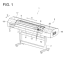
- ink-jet recording apparatus 1 is an ink-jet recording apparatus of a serial print type, comprising printer 2 and support table 3 for supporting the printer 2 from under the printer 2. Further, in the central section of the printer 2, platen 4 for supporting recording medium P from the non-recording surface thereof is arranged extending in the longitudinal direction of the printer 2.
- guide rail 5 in a rod shape extending in the longitudinal direction of the printer 2.
- the guide rail 5 supports carriage 6, which is freely and reciprocally movable in main scanning direction X along the guide rail 5 with a driving mechanism (not shown).
- the printer 2 is provided with a conveying mechanism (not shown) for conveying the recording medium P in sub scanning direction Y which is orthogonal to the main scanning direction X.
- the conveying mechanism comprises, for example, a conveying motor and conveying roller, not shown.
- the conveying roller is rotated by driving the conveying motor to convey the recording medium P along the platen 4 from upstream to downstream in the sub scanning direction Y.
- the conveying mechanism intermittently conveys the recording medium P, repeating conveying and stop of the recording medium P with synchronization with the operation of the carriage 6.
- recoding heads 7, 7, ... which are correspondent to respective colors (yellow (Y), magenta (M), cyan (C), and black (K)) to be used on the ink-jet recording apparatus 1 of the present embodiment, are mounted on the carriage 6.
- the recording heads 7,7, ... have an outer shape formed almost in a rectangular parallelepiped, and are arranged side by side such that the longitudinal directions thereof are parallel to each other.
- ink-jetting openings 8, 8, ... of a plurality of nozzles (not shown) formed on a line along the longitudinal direction of the recording heads 7, 7, ... are provided so that the recording heads 7, 7, ...
- the inks to be used on the ink-jet recording apparatus are not limited to the above, and, for example, light yellow (LY), light magenta (LM), light cyan (LC), or the like, may also be used.
- recording heads corresponding to the respective colors are mounted on the carriage.
- the arrangement of nozzles and the shape of jetting openings 8, 8, ... are not limited to the above examples.
- the carriage 6 is provided with intermediate tanks 9, 9, ... for supplying ink, in a number corresponding to the respective recording heads 7, 7, ..., wherein the respective recording heads 7, 7, ... are connected with the intermediate tanks 8, 8, ... through ink supply tubes 10, 10 , ....
- the intermediate tanks 9, 9, ... are connected with ink tanks 11, 11, ... provided at one end of the motion range of the carriage 6, which is outside of the platen 4, through ink supply paths, not shown, wherein inks are, as needed, supplied from the ink tanks 11, 11, ... to the respective recording heads 7, 7, ... through the intermediate tanks 9, 9, 9, ....
- UV-ray emitting devices 12, 12 as light emitting devices are provided in contact with the respective sides of the carriage 6.
- description of a single unit of UV-ray emitting device 12 will be given for simplicity. However, it should be understood that the description below is common to the both units of UV-ray emitting devices 12, 12 and members related thereto.
- the UV-ray emitting device 12 is provided with light source cover 13 having an opening on one end face thereof and formed in a box shape, wherein the opening of the light source cover 13 is arranged facing the recording surface of the recording medium P.
- low pressure mercury lamp 14 is provided as a light source for emitting UV-rays to cure and fix UV-curable ink having impacted onto the recording medium P.
- the low pressure mercury lamps 14 is, as shown in Fig. 2b, comprised of light emitting tube 15 arranged parallel to the sub scanning direction Y, the tube 15 having a plurality of bent sections 60, 60, ... at predetermined positions and being bent such that the length of the light emitting tube 15 is greater than the longitudinal length of the recording heads 7, 7, ... , and cylindrical metal caps 16, 16 are provided at both ends of the light emitting tube 15. By conducting a current between the metal caps 16, 16, the light emitting tube 15 emits light.
- the shape of the light emitting tube 15 of the low pressure mercury lamp 14 is not limited to one shown in Fig. 2b, and it is also allowed to use a type of light emitting tube formed in a U-shape provided with a bent section only at a single portion and fitted with metal caps at both ends of the light emitting tube.
- the low pressure mercury lamp 14 has a characteristic of varying UV-ray generation energy depending on the temperature of the metal caps 16, and therefore, the low pressure mercury lamps 14 is arranged to make the UV-ray generation energy even, when the temperatures of the metal caps 16 become a predetermined temperature.
- a cooling fan may be provided in the vicinity of the metal caps 16, 16.
- the printer 2 is covered with cover 17 so that the platen 4 and the entire motion range of the carriage 6 are shielded from outside, thereby preventing leakage of light from the UV-ray emitting device 12 to the outside.
- suction fan 18 for cooling inside the cover 17 by sucking the ambient air is provided on one end face of the cover 17.
- exhausting fan 19 for exhausting the air from inside the cover 17 to outside the cover 17 is provided.
- a cooling mechanism for circulating cooling water for example, may be provided in the vicinity of the suction fan 18 for cooling. In this case, it is possible to supply air having been cooled to a lower temperature than that of the ambient air into inside the cover 17 by the suction fan 18, which enables more effective cooling inside the cover 17.
- Each ink used in the present embodiment is photocurable ink having a characteristic of being cured by exposure to UV-ray as light and containing at least a polymer compound (including a known polymer compound), a photoinitiator, and a colorant.
- Photocurable inks can be broadly categorized into radical polymer inks containing a radical polymer compound as a polymer compound and cation polymer inks containing a cation polymer compound as the same.
- UV-ray curing inks of a cation polymer system which causes difference in curing reaction depending on the humidity and temperature are used.
- the cation polymer inks used in the present embodiment are a mixture containing, at least: a cation polymer compound such as an oxetan compound, an epoxy compound, a vinyl ether compound, or the like; a photo-cation initiator; and a colorant.
- a cation polymer compound such as an oxetan compound, an epoxy compound, a vinyl ether compound, or the like
- a photo-cation initiator such as an oxetan compound, an epoxy compound, a vinyl ether compound, or the like
- a colorant such as an oxetan compound, an epoxy compound, a vinyl ether compound, or the like.
- the recording medium P used in the present embodiment it is possible to apply recording media of materials such as plain paper applicable to common ink-jet recording apparatuses, recycled paper, gloss paper, other various kinds of paper, various kinds of textile, bonded textile, resin, metal, glass, and others.
- a roll type, a cut-sheet type, a plate type, and the like can be applied as the type of the recording medium P.
- the carriage 6 reciprocally moves along the guide rail 5, while required inks are jetted from the ink-jetting openings 8, 8, ... of the recording head 7, 7, ..., according to a certain image data.
- the low-pressure mercury lamp 14 of the UV-ray emitting device 12 starts burning, UV-rays are emitted to the inks having been jetted onto the recording medium P, thereby, the inks are cured and fixed, and thus an image is recorded on the recording surface of the recording medium P.
- the printer 2 is covered with the cover 17 so that UV-rays emitted by the UV-ray emitting device 12 do not leak outside, thereby allowing it to safely perform image recording operation even in indoor environment in office, for example.
- the suction fan 18 and the exhausting fan 19 are provided on the respective sides of the cover 17 so that air inside the cover 17 and ambient air circulate, the temperature inside the cover 17 does not rise excessively, making it possible to cure and fix ink by exposure to UV-ray safely all the time and realize image recording in a high image quality.
- the light emitting tubes 15, which is the light source, of the low-pressure mercury lamp 14 is bent, light for the same illumination intensity as that in the case of providing a plurality of line-type light sources can be emitted by a single low-pressure mercury lamp 14. Therefore, the number of metal caps 16, 16 arranged inside the UV-ray emitting device can be decreased, and thus it is possible to prevent a drop in the light emission efficiency of the low-pressure mercury lamp 14 caused by thermal interference between the metal caps 16, 16.
- the cover 17 is arranged to cover the entire printer 2, the cover 17 is essentially required to prevent leakage of UV-rays emitted by the UV-ray emitting devices 12, 12 to outside. Therefore, for example, the cover 17 may be arranged to cover only the UV-ray emitting devices 12, 12 and the recording heads 7, 7, ..., or, it is also allowed to cover the entire ink-jet recording apparatus 1 and perform image recording in a sealed space.
- the ink-jet recording apparatus 1 in the case of the ink-jet recording apparatus 1, the ink-jet recording apparatus 1 being applied with the recording heads 7, 7, ..., of the invention, the recording heads 7, 7, ... mounted on the carriage 6 are reciprocally moved in the main scanning direction X, while the recording medium P is conveyed in the sub scanning direction Y and the recording heads 7, 7, ... are controlled to jet inks during the conveyance of the recording medium P.
- the ink-jet recording apparatus 1 of a serial head type forms an image.
- the low-pressure mercury lamps 14, 14 are used as the light sources of the UV-ray emitting devices 12, 12, the light sources are not limited to these, and it is also possible to apply, for example, high-pressure mercury lamps, metal halide lamps, hot-cathode tubes, cold-cathode tubes, excimer lamps, UV-ray lasers, LEDs (Light Emitting Diodes), etc.
- the UV-ray emitting devices 12, 12 are provided with the respective low-pressure mercury lamps 14, 14, in other words, each UV-ray emitting device is provided with a single low-pressure mercury lamp.
- the quantities of the low-pressure mercury lamps 14, 14 arranged on the UV-ray emitting devices 12, 12 are not limited to this, and a plurality of lamps may be provided for each.
- image recording is performed using inks curable by exposure to UV-rays
- the types of inks are not limited to these, and it is also possible to use, for example, inks curable by exposure to light other than UV-rays, such as electron beams, X-rays, visible light, infrared rays, etc.
- the inks are applied with a polymer compound that polymerizes and gets cured by light other than UV-rays, and a photo-initiator that initiates a polymerization reaction between polymer compounds by light other than UV-rays.
- light sources that emit this type of light are applied instead of the UV-ray light sources.
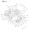
- An ink-jet recording apparatus of the present embodiment is, likewise in the first embodiment, a serial head type ink-jet recording apparatus provided with, as shown in Fig. 3, carriage 21 having mounted thereon recording heads 22, 22, ... which jet inks in the respective colors of yellow (Y), magenta (M), cyan (C), and black (K) onto recording medium P.
- the carriage 21 is designed to reciprocally move along a guide rail (not shown) in a main scanning direction X by a driving mechanism (not shown).
- the recording heads 22, 22, ... are respectively connected with intermediate tanks 23, 23, ... which store inks in the respective colors through ink supply tubes 24, 24, ....
- UV-ray emitting devices 25, 25 are provided as light emitting devices for curing ink having been jetted onto recording medium P by emitting UV-rays to the ink.
- the UV-ray emitting device 25 has a box shape which is opened toward the side of recording medium P, and has light source cover 26 of which the end on the upstream side in sub scanning direction Y protrudes upward.
- the UV-ray emitting devices 25 is provided with lid section 27 fitted on the end on the upstream side, in the sub scanning direction Y, of the light source cover 26 through a hinge mechanism, not shown, arranged at the bottom section of the light source cover 26.
- the lid section 27 is freely openable and closable with respect to the light source cover 26 by rotation around the bottom section of the light source cover 26 as a rotation axis.
- the structure for opening and closing the lid section 27 is not limited to the example shown. Further, the lid section 27 may be arranged such that the lid section 27 opens and closes by rotation around a portion other than the bottom section of the light source cover 26 as the rotation axis, for example, applying the top end section of the light source cover 26 as the rotation axis.
- low-pressure mercury lamp 28 is housed as a light source for emitting UV-ray to cure the inks.
- the low-pressure mercury lamp 28 is arranged in the sub scanning direction Y, and comprises light emitting tube 29 having a plurality of bent sections 50, 50, ... at predetermined positions and being bent such that the length thereof is preferably greater than the longitudinal length of the recording heads 22, 22, ... , and comprises cylindrical metal caps 30, 30 fitted at both ends of the light emitting tube 29.
- the metal caps 30, 30 has a filament, not shown, coated with an electronic radiating material (emitter), wherein a current is conducted through the metal caps 30, 30 so as to cause the light emitting tube 29 to emit light.
- Each light emitting tube 29 has bent sections 50, 50 bent approximately at a right angle in the vicinities of the respective sections connected with the metal caps 30, 30, wherein the metal caps 30, 30 extend upward along the protrusion of the light source cover 26 and are approximately orthogonal to the light emitting plane.
- the shape of the light emitting tube 29 of the low-pressure mercury lamp 28 is not limited to the shape shown in Figs. 5a and 5b.
- a portion of the light source cover 26 on the downstream side in the sub scanning direction Y is arranged as a light emitting tube housing section 31 for housing the light emitting tube 29.
- a light emitting tube housing section 31 for housing the light emitting tube 29.
- reflecting member 32 for reflecting, onto the recording medium P, UV-rays having been emitted and diffused from the light emitting tube 29 is provided, the reflecting member 32 covering the light emitting tube 29.
- a reflecting plate of aluminum of a high purity which efficiently reflects UV-rays in the entire wavelength range is applied, for example.
- a cold mirror formed glass plate which is made by vapor depositing of a thin film of a metal compound principally containing aluminum is preferable because it efficiently reflects UV-rays, while it transmits visible light and infrared rays, which do not contribute to curing of ink, behind the mirror, thereby reducing a drop in light emission efficiency due to heat generation by the light emitting tube 29.
- a protection member 33 for preventing adherence of dirt, such as ink mist, to the light emitting tube 29 and preventing the recording medium P from contacting the light emitting tube 29 when the recording medium P floats off a platen (not shown) due to convey failure.
- the protection member 33 is supported by frame-shaped supporting member 34 provided along the inner surface at the bottom of the light source cover 26.
- the protection member 33 is formed of a material such as transparent glass or transparent resin in a plate shape, and is replaceable.
- normal silica glass, synthetic silica glass, or the like which efficiently transmits the UV-ray wavelength range, and particularly, UV-C range (up to 280 nm), is preferably employed.
- sub scanning direction restraining member 35 is arranged as a first light emitting tube restraining member for restraining the position of the low-pressure mercury lamp 28 in the sub scanning direction Y when the low-pressure mercury lamp 28 is received by the light source cover 26.
- main scanning direction restraining member 36 is arranged as a second light emitting tube restraining member for restraining the position of the low-pressure mercury lamp 28 in the main scanning direction X when the low-pressure mercury lamp 28 is received by the light source cover 26.
- the sub scanning direction restraining member 35 and the main scanning direction restraining member 36 are formed, foe example, of a metal plate having spring characteristics.
- the material of the sub scanning direction restraining member 35 and the main scanning direction restraining member 36 is not limited to the example, shown here, and it is possible to apply any material having spring characteristics and an enough heat resistance against the heat generated by the light emitting tube 29.
- the protrusion of the light source cover 26 is used as metal cap housing section 40 for housing the metal caps 30.
- a metal cap cooling fan 43 for releasing heat and cooling the metal caps 30, 30 by feeding the ambient air from the ambient air feeding opening 41 and exhausting air from the air exhausting slits 42 with rotation drive.
- This metal cap cooling fan 43 is arranged such that the rotation velocity thereof is variable by changing the voltage applied to a drive motor for rotationally driving the fan.
- plate-shaped body-side partition member 45 having heat insulation characteristics, to part these two sections is arranged.
- the positions corresponding to those on the light emitting tube 29 there are respectively formed cutout sections 45a, 45b for receiving the end sections, on the light emitting tube 29 side, of the metal caps 30, 30, wherein the end sections, on the light emitting tube 29 side, of the metal caps 30, 30 contact these cutout sections 45a and 45b.
- the position corresponding to that of the body-side partition member 45 there is arranged plate-shaped lid-side partition member 46, having heat insulation characteristics, to part the light emitting tube housing section 31 and the metal cap housing section 40.
- metal cap restraining member 47 for restraining the positions of the metal caps 30, 30 is provided, wherein the metal cap restraining member 47 is formed along the circumferential surface, on the downstream side in the sub scanning direction Y, of the metal caps 30, 30.
- press member 48 for pressing the metal caps 30, 30 against the restraining member 47 is arranged, thereby fixing the metal caps 30, 30.
- the press member 48 is formed of, for example, a metal plate or the like, having spring characteristics.
- the material that forms the press member 48 is not limited to the example described here, and it is possible to apply any material having spring characteristics.
- metal cap temperature sensor 49 for detecting the temperature of the metal cap 30 is provided.
- the ink-jet recording apparatus 1 comprises a control section (not shown) for controlling the operations of the light emitting tube cooling fans 39, 39, metal cap cooling fans 43, 43, and the like.
- a control section for controlling the operations of the light emitting tube cooling fans 39, 39, metal cap cooling fans 43, 43, and the like.
- detection results are transmitted from the metal cap temperature sensors 49, 49.
- the control section controls the rotation velocities of the metal cap cooling fans 43, 43 so that the temperatures of the metal caps 30, 30 are maintained to a predetermined temperature.
- control section rotationally drives the light emitting tube cooling fans 39, 39 at a predetermined time after the low-pressure mercury lamps 28, 28 start burning.
- control section stops the rotation of the light emitting tube cooling fans 39, 39.
- the recording medium P is conveyed in the sub scanning direction Y by a conveying mechanism.
- the carriage 21 reciprocally moves along a guide rail, and required ink is jetted, according to certain image data, from the nozzles of the recording heads 22, 22, ....
- the low-pressure mercury lamps 28, 28 of the UV-ray emitting devices 25, 25 start burning and emit UV-rays onto the ink-jetted on the recording medium P, thereby curing and fixing the ink to record an image on the recording surface of the recording medium P.
- the temperatures of the metal caps 30, 30 and the light emitting tubes 29, 29 rise.
- the temperatures of the metal caps 30, 30 are detected all the time by the metal cap temperature sensors 49, 49. According to the detected temperatures, the rotation velocities of the metal cap cooling fans 43, 43 are controlled by the control section, and thus the temperatures of the metal caps 30, 30 are adjusted to a predetermined temperature.
- the control section starts the light emitting tube cooling fans 39, 39 rotating.
- the light emitting tubes 29, 29 are cooled, not partially, but uniformly as a whole, which adjusts the temperature difference between the light emitting tubes 29, 29 and the metal caps 30, 30 to be in the range of temperature difference that allows high light emission efficiency.
- each light emitting tube 29 has bent sections 50, 50 below the metal caps 30, 30, blackening does not extends further than the bent sections 50, 50, and thus, the illumination intensity by the light emitting tube 29 housed in the light emitting tube housing section 31 is maintained almost constant.
- a user When replacing a low-pressure mercury lamp 28, a user, first opens the lid section 27 of a UV-ray emitting device 25 that requires replacement of the low-pressure mercury lamp 28, draws out the low-pressure mercury lamp 28 housed in the light source cover 26 from the downstream side to the upstream side in the sub scanning direction Y, and takes out the low-pressure mercury lamp 28 from the light source cover 26. Next, with the lid section 27 opened, the user inserts a new low-pressure mercury lamp 28 into the light source cover 26 from the upstream side to the down stream side in the sub scanning direction.
- the tip section of the light emitting tube 29 is held by the sub scanning direction restraining member 35 so that the position of the low-pressure mercury lamp 28 in the sub scanning direction Y is restrained.
- the main scanning direction restraining member 36 holds the both sides of the light emitting tube 29, and the position of the low-pressure mercury lamp 28 in the main scanning direction X is restrained.
- the metal caps 30, 30 contact the restraining member 47, while the light emitting tube 29 connected to the metal caps 30, 30 contacts the body-side partition member 45.
- the press member 48 arranged on the lid section 27 presses the metal caps 30, 30 against the restraining member 47, thereby fixing the metal caps 30, 30. Still further, when the lid section 27 is closed, the body-side partition member 45 and the lid-side partition member 46 are combined, and thus, the light emitting tube housing section 31 and the metal cap housing section 40 are parted.
- the ink-jet recording apparatus 1 causes thermal interference little, maintains the light emission efficiency in fine condition, and cures ink with stable output of UV-rays. Therefore, fine images can be stably obtained.
- blackening of the vicinities of the electrodes of the metal caps 30, 30 caused by spattering of electronic radiation material (emitter) coated on a filament of metal caps 30, 30 does not extend further than the bent sections. Therefore, it is possible to emit light, maintaining the illumination intensity by each light emitting tube 29 housed in the light emitting tube housing section 31 almost constant.
- the invention is applied to the ink-jet recording apparatus 1 of a serial head type that records an image in such a way that the recording heads 22, 22, ... mounted on the carriage 21 are reciprocally moved in the main scanning direction X, and the recording medium P is conveyed in the sub scanning direction Y, wherein ink is jetted from the recording heads 22, 22, ....
- the invention can also be applied to an ink-jet recording apparatus of a line head type that forms an image in such a way that ink is jetted from recording heads which are provided for the entire width of a recording medium P and fixed above the recording medium P, and the recording medium P is conveyed in a direction orthogonal to the recording heads.
- a light emitting device is arranged on the downstream side, in the conveyance direction of the recording medium, with respect to the recording heads, and parallel to the longitudinal direction of the recording heads.
- a lid section can be arranged at either end of the light emitting device and opened and closed so that a low-pressure mercury lamp can be replaced by moving it in the direction orthogonal to the conveyance direction of the recording medium.
- the position of arranging a lid section is not limited to this shown here as an example, and a low-pressure mercury lamp may be replaced in such a way, for example, that a lid section is arranged on a side face, of a light emitting device, which does not face recording heads, the lid section is opened and closed, and the low-pressure mercury lamp is moved in the conveyance direction of a recording medium.
- the user opens the lid section 27 provided at a portion, of the light source cover 26, on the upstream side in the sub scanning direction Y so as to draw out the low-pressure mercury lamp 28 housed in the light source cover 26 from the downstream side to the upstream side in the sub canning direction Y, and thus takes out the low-pressure mercury lamp 28 from inside the light source cover 26.
- the direction in which the low-pressure mercury light 28 is drawn out is not limited to this.
- a lid section 27 may be arranged on the side face of a light source cover 26 so that a low-pressure mercury lamp 28 is drawn out in the main scanning direction X.
- lid section 27 may be arranged on a portion, of light source cover 26, on the downstream side in the sub scanning direction Y so that low-pressure mercury lamp 28 is drawn out from the upstream side to the downstream side in the sub scanning direction Y.
- a cooling fan is employed as a means for cooling the metal caps 30, 30 and each light emitting tube 29, the means for cooling the metal caps 30, 30 and each light emitting tube 29 is not limited to this.
- a Peltier module which is made by serially and electrically connecting a plurality of Peltier devices, which are thermoelectric cooling devices, may be arranged through a thermal conducting section that is made of a material with a high thermal conductivity, the thermal conducting section covering around the two metal caps 30, 30.
- a direct current is applied to the Peltier devices from a power supply section so that the Peltier module absorbs heat from a face of the Peltier devices and releases heat from another face, wherein it is possible to switch the cooling face and the heat releasing face by reversing the direction of the current applied to the Peltier devices.
- thermoelectric module on a surface facing a heat-conducting section contact-surface which is in contact with the heat-conducting section of the Peltier module, wherein the heat sink releases heat having been absorbed from a cooling surface and transferred when the heat-conducting section contact-surface functions as the cooling surface
- a cooling fan on the top of the heat sink, for diffusing the heat radiated from the heat sink.
- a Peltier module through a plate-shaped heat-conducting section made of a material with a high thermal conductivity on the top of the reflecting member 32, and control the heat motion by the Peltier module, according to the temperature of the light emitting tube 29.
- a water jacket in contact with the metal caps 30, 30 and a water cooling tank for supply of cooling water to the water jacket.
- temperature control can be performed by controlling the supply amount of the cooling water.
- a water jacket on the top of the reflecting member 32 to supply cooling water, thereby adjusting the temperature of the light emitting tube 29.
- each light source cover 26 is formed protruding upward; the metal caps 30, 30 are extended upward along the protrusion of the light source cover 26 from the both ends of the light emitting tube 29; and the protrusion is used as the metal cap housing section 40 for housing the metal caps 30, 30.
- the shape of the light source cover 26 is not limited to this, and it is possible, for example, to form a light source cover 26 into a box-shape without forming a protrusion, and to provide metal caps in the sub scanning direction Y.
- a metal cap cooling fan and a light emitting tube cooling fan respectively at the positions corresponding to the metal cap receiving section and the light emitting tube receiving section which are in the upper portion of the light source cover and parted by the partition members. Still further, if ink-jetted from the recording heads 22, 22, ... and others are not affected by air exhausting, air exhausting and air absorbing may be reversed.
- the invention is not limited to the present embodiment, the same as in the case of the first embodiment.
Landscapes
- Health & Medical Sciences (AREA)
- General Health & Medical Sciences (AREA)
- Toxicology (AREA)
- Ink Jet (AREA)
- Ink Jet Recording Methods And Recording Media Thereof (AREA)
- Inks, Pencil-Leads, Or Crayons (AREA)
Abstract
Description
Claims (14)
- An ink-jet recording apparatus, comprising:a recording head to jet photocurable ink onto a recording medium, wherein the photocurable ink is cured by being exposed to light; anda light emitting device having a light source to emit light to cure the photocurable ink, the light source including a light emitting tube and metal caps provided at both ends of the light emitting tube, wherein,the light emitting tube has a bent section.
- The ink-jet recording apparatus of claim 1, wherein,
one metal cap and the other one metal cap of the light source are arranged on the same side. - The ink-jet recording apparatus of claim 1, wherein,
the light emitting tube comprises at least two line-shaped tubes and the bent section includes a curved section for connecting the two line-shaped tubes. - The ink-jet recording apparatus of claim 1, wherein,
the bent section includes two bent connecting sections, each bent connecting section being formed at a part of the light emitting tube in a vicinity of a respective joint section that connects the light emitting tube and the respective metal cap such that a direction of the metal cap is orthogonal to a light emitting plane. - The ink-jet recording apparatus of claim 3, wherein,
the bent section further includes two bent connecting sections, each connecting section being formed at a part of the light emitting tube in a vicinity of a respective joint section that connects the light emitting tube and the respective metal cap such that a direction of the metal cap is orthogonal to a light emitting plane. - The ink-jet recording apparatus of claim 1, wherein,
the light source is attachable and detachable to and from the light emitting device. - The ink-jet recording apparatus of claim 6, wherein,
the light source is attachable and detachable to and from the light emitting device by moving the light source approximately parallel to a recording surface of the recording medium. - The ink-jet recording apparatus of claim 6, wherein, the light emitting device comprises:a light source cover that has a metal cap restraining member for restraining the position of the two metal caps and can house the light source therein; anda lid section that can be freely opened and closed with respect to the light source cover, wherein,the lid section has a pressing member for pressing the metal caps against the metal cap restraining member.
- The ink-jet recording apparatus of claim 6, wherein, the light emitting device comprises:a first light emitting tube restraining member for restraining a position of the light source in a convey direction of the recording medium; anda second light emitting tube restraining member for restraining the position of the light source in a direction orthogonal to the convey direction of the recording medium.
- The ink-jet recording apparatus of claim 1, wherein,
the recording head is a serial print type that jets the ink onto the recording material while the recording head moves in the direction orthogonal to the convey direction of the recording medium. - The ink-jet recording apparatus of claim 1, wherein,
the recording head is a line print type that jets the ink from a predetermined fixed position to the recording medium moving in the convey direction. - The ink-jet recording apparatus of claim 1, wherein, the light source is a low pressure mercury lamp.
- The ink-jet recording apparatus of claim 1, wherein, light emitted by the light emitting device is UV-ray.
- The ink-jet recording apparatus of claim 1, wherein,
the ink is a cation polymer ink containing a cation polymer compound.
Applications Claiming Priority (4)
| Application Number | Priority Date | Filing Date | Title |
|---|---|---|---|
| JP2003331905 | 2003-09-24 | ||
| JP2003331905 | 2003-09-24 | ||
| JP2004229465 | 2004-08-05 | ||
| JP2004229465A JP4649906B2 (en) | 2003-09-24 | 2004-08-05 | Inkjet recording device |
Publications (2)
| Publication Number | Publication Date |
|---|---|
| EP1518699A1 true EP1518699A1 (en) | 2005-03-30 |
| EP1518699B1 EP1518699B1 (en) | 2010-11-24 |
Family
ID=34197244
Family Applications (1)
| Application Number | Title | Priority Date | Filing Date |
|---|---|---|---|
| EP20040104477 Expired - Lifetime EP1518699B1 (en) | 2003-09-24 | 2004-09-16 | Ink-jet recording apparatus |
Country Status (4)
| Country | Link |
|---|---|
| US (1) | US7237889B2 (en) |
| EP (1) | EP1518699B1 (en) |
| JP (1) | JP4649906B2 (en) |
| DE (1) | DE602004030196D1 (en) |
Families Citing this family (10)
| Publication number | Priority date | Publication date | Assignee | Title |
|---|---|---|---|---|
| US7549740B2 (en) * | 2004-03-26 | 2009-06-23 | Konica Minolta Holdings, Inc. | Image recording apparatus |
| JP4238907B2 (en) | 2006-10-18 | 2009-03-18 | セイコーエプソン株式会社 | Inkjet recording device |
| GB0624123D0 (en) * | 2006-12-02 | 2007-01-10 | Xennia Technology Ltd | Inkjet printing apparatus and method |
| JP5239151B2 (en) * | 2006-12-07 | 2013-07-17 | コニカミノルタエムジー株式会社 | Inkjet recording device |
| JP5714586B2 (en) * | 2009-08-27 | 2015-05-07 | エアー・モーション・システムズ・インコーポレイテッドAir Motion Systems, Inc. | Multi-row expandable LED-UV module |
| JP5682750B2 (en) | 2010-03-30 | 2015-03-11 | セイコーエプソン株式会社 | Inkjet recording apparatus and inkjet recording method |
| JP5903910B2 (en) * | 2011-02-21 | 2016-04-13 | セイコーエプソン株式会社 | Droplet discharge device |
| CN112895719A (en) * | 2021-01-22 | 2021-06-04 | 温州恒寅贸易有限公司 | Prevent short circuit and be applicable to UV flatbed printer of different material air brushing |
| CN114701259B (en) * | 2022-06-07 | 2022-09-09 | 佛山市美嘉陶瓷设备有限公司 | UV prints passageway integrated configuration |
| JP2025064042A (en) * | 2023-10-05 | 2025-04-17 | コニカミノルタ株式会社 | Fixing device of image forming apparatus, and image forming apparatus |
Citations (2)
| Publication number | Priority date | Publication date | Assignee | Title |
|---|---|---|---|---|
| US20020139004A1 (en) | 2001-03-27 | 2002-10-03 | Andreas Laudat | Device for drying solvent-based ink |
| US20030035037A1 (en) * | 2001-04-13 | 2003-02-20 | Vutek, Inc. | Radiation treatment for ink jet fluids |
Family Cites Families (19)
| Publication number | Priority date | Publication date | Assignee | Title |
|---|---|---|---|---|
| US2248618A (en) * | 1939-04-01 | 1941-07-08 | Robert A Fischer | Bactericidal apparatus |
| US2544781A (en) * | 1945-12-22 | 1951-03-13 | Leroy C Doane | Shock resistant luminaire for use with fluorescent tubes |
| US2769897A (en) * | 1954-12-21 | 1956-11-06 | Hess Company | Fluorescent light fixture |
| JPS59112463U (en) * | 1983-01-20 | 1984-07-30 | 株式会社東芝 | Fluorescent lamp for display elements |
| JPS63289781A (en) * | 1987-05-22 | 1988-11-28 | Toshiba Electric Equip Corp | Lighting fixture |
| JPS63302939A (en) * | 1987-05-29 | 1988-12-09 | Toshiba Electric Equip Corp | Radiating equipment for ultraviolet ray |
| JPH0589836A (en) * | 1991-05-22 | 1993-04-09 | Toshiba Lighting & Technol Corp | Ultraviolet ray irradiation source, lighting device, and ultraviolet ray irradiation device |
| JPH0538863A (en) * | 1991-08-05 | 1993-02-19 | Fuji Photo Film Co Ltd | Optical fixing device for thermal printer |
| US5835679A (en) * | 1994-12-29 | 1998-11-10 | Energy Converters, Inc. | Polymeric immersion heating element with skeletal support and optional heat transfer fins |
| JPH10302922A (en) * | 1997-04-30 | 1998-11-13 | Tec Corp | Fluorescent lamp socket |
| US6392206B1 (en) * | 2000-04-07 | 2002-05-21 | Waltow Polymer Technologies | Modular heat exchanger |
| JP2001310454A (en) | 2000-04-27 | 2001-11-06 | Mitsubishi Electric Corp | Inkjet printer |
| JP2003054017A (en) * | 2001-08-20 | 2003-02-26 | Fuji Photo Film Co Ltd | Photofixing system for thermal printer |
| US6663239B2 (en) * | 2001-10-31 | 2003-12-16 | Hewlett-Packard Development Company, L.P. | Microwave applicator for inkjet printer |
| JP2003145725A (en) | 2001-11-09 | 2003-05-21 | Konica Corp | Ink jet printer |
| US6777462B2 (en) * | 2001-11-23 | 2004-08-17 | Xerox Corporation | Ink compositions containing sodium tetraphenylboride |
| JP2003261799A (en) * | 2002-03-08 | 2003-09-19 | Konica Corp | Active light-curable ink and ink jet recording method using the same |
| JP2004009359A (en) * | 2002-06-04 | 2004-01-15 | Konica Minolta Holdings Inc | Ink jet imaging method |
| US6696802B1 (en) * | 2002-08-22 | 2004-02-24 | Fusion Uv Systems Inc. | Radio frequency driven ultra-violet lamp |
-
2004
- 2004-08-05 JP JP2004229465A patent/JP4649906B2/en not_active Expired - Fee Related
- 2004-09-16 EP EP20040104477 patent/EP1518699B1/en not_active Expired - Lifetime
- 2004-09-16 DE DE200460030196 patent/DE602004030196D1/en not_active Expired - Lifetime
- 2004-09-20 US US10/945,335 patent/US7237889B2/en not_active Expired - Fee Related
Patent Citations (2)
| Publication number | Priority date | Publication date | Assignee | Title |
|---|---|---|---|---|
| US20020139004A1 (en) | 2001-03-27 | 2002-10-03 | Andreas Laudat | Device for drying solvent-based ink |
| US20030035037A1 (en) * | 2001-04-13 | 2003-02-20 | Vutek, Inc. | Radiation treatment for ink jet fluids |
Non-Patent Citations (1)
| Title |
|---|
| RICHARD FORSTER (EDITOR): "Lamp Guide 2001", 2001, LIGHTING INDUSTRY FEDERATION LIMITED, LONDON, UK, XP002309716 * |
Also Published As
| Publication number | Publication date |
|---|---|
| EP1518699B1 (en) | 2010-11-24 |
| US7237889B2 (en) | 2007-07-03 |
| JP4649906B2 (en) | 2011-03-16 |
| JP2005119270A (en) | 2005-05-12 |
| DE602004030196D1 (en) | 2011-01-05 |
| US20050062822A1 (en) | 2005-03-24 |
Similar Documents
| Publication | Publication Date | Title |
|---|---|---|
| US7744207B2 (en) | Ink jet printer | |
| JP5071093B2 (en) | UV irradiation equipment | |
| WO2004108417A1 (en) | Ink jet printer using uv ink | |
| US10589529B2 (en) | Printing apparatus and printing method | |
| US7237889B2 (en) | Ink-jet recording apparatus | |
| JP2010000735A (en) | Ultraviolet curing-type inkjet printer and light source unit for ultraviolet curing-type inkjet printer | |
| JP2009226692A (en) | Inkjet printer | |
| US7661807B2 (en) | Ultraviolet rays emitter | |
| US20090115827A1 (en) | Recording apparatus and liquid ejecting apparatus | |
| US7407253B2 (en) | Inkjet recording apparatus | |
| JP4635500B2 (en) | Ultraviolet irradiation device and image recording apparatus using the same | |
| US7222953B2 (en) | Ink jet recording apparatus using a temperature detector to control the curing of ink | |
| CN101412316A (en) | Recording apparatus and liquid ejecting apparatus | |
| JP2011046096A (en) | Recording device | |
| EP1508452A1 (en) | Ink jet printer | |
| US20050253914A1 (en) | Ink jet recording apparatus | |
| JP2005125752A (en) | Ink jet recorder | |
| US20190315132A1 (en) | Inkjet printer | |
| JP2007069474A (en) | Inkjet device | |
| US7014285B2 (en) | Ink jet printer | |
| JP4947201B2 (en) | Printing device | |
| JP2023108089A (en) | Liquid ejector | |
| JP2008168560A (en) | Ultraviolet irradiation device and recording apparatus equipped with the ultraviolet irradiation device | |
| JP2005231235A (en) | Ink jet recorder | |
| JP5003805B2 (en) | Printing device |
Legal Events
| Date | Code | Title | Description |
|---|---|---|---|
| PUAI | Public reference made under article 153(3) epc to a published international application that has entered the european phase |
Free format text: ORIGINAL CODE: 0009012 |
|
| AK | Designated contracting states |
Kind code of ref document: A1 Designated state(s): AT BE BG CH CY CZ DE DK EE ES FI FR GB GR HU IE IT LI LU MC NL PL PT RO SE SI SK TR |
|
| AX | Request for extension of the european patent |
Extension state: AL HR LT LV MK |
|
| 17P | Request for examination filed |
Effective date: 20050901 |
|
| AKX | Designation fees paid |
Designated state(s): DE FR GB |
|
| 17Q | First examination report despatched |
Effective date: 20071012 |
|
| RAP1 | Party data changed (applicant data changed or rights of an application transferred) |
Owner name: KONICA MINOLTA MEDICAL & GRAPHIC, INC. |
|
| GRAP | Despatch of communication of intention to grant a patent |
Free format text: ORIGINAL CODE: EPIDOSNIGR1 |
|
| GRAS | Grant fee paid |
Free format text: ORIGINAL CODE: EPIDOSNIGR3 |
|
| GRAA | (expected) grant |
Free format text: ORIGINAL CODE: 0009210 |
|
| AK | Designated contracting states |
Kind code of ref document: B1 Designated state(s): DE FR GB |
|
| REG | Reference to a national code |
Ref country code: GB Ref legal event code: FG4D |
|
| REF | Corresponds to: |
Ref document number: 602004030196 Country of ref document: DE Date of ref document: 20110105 Kind code of ref document: P |
|
| PLBE | No opposition filed within time limit |
Free format text: ORIGINAL CODE: 0009261 |
|
| STAA | Information on the status of an ep patent application or granted ep patent |
Free format text: STATUS: NO OPPOSITION FILED WITHIN TIME LIMIT |
|
| 26N | No opposition filed |
Effective date: 20110825 |
|
| REG | Reference to a national code |
Ref country code: DE Ref legal event code: R097 Ref document number: 602004030196 Country of ref document: DE Effective date: 20110825 |
|
| PGFP | Annual fee paid to national office [announced via postgrant information from national office to epo] |
Ref country code: DE Payment date: 20140911 Year of fee payment: 11 |
|
| PGFP | Annual fee paid to national office [announced via postgrant information from national office to epo] |
Ref country code: GB Payment date: 20140910 Year of fee payment: 11 |
|
| PGFP | Annual fee paid to national office [announced via postgrant information from national office to epo] |
Ref country code: FR Payment date: 20140906 Year of fee payment: 11 |
|
| REG | Reference to a national code |
Ref country code: DE Ref legal event code: R119 Ref document number: 602004030196 Country of ref document: DE |
|
| GBPC | Gb: european patent ceased through non-payment of renewal fee |
Effective date: 20150916 |
|
| REG | Reference to a national code |
Ref country code: FR Ref legal event code: ST Effective date: 20160531 |
|
| PG25 | Lapsed in a contracting state [announced via postgrant information from national office to epo] |
Ref country code: DE Free format text: LAPSE BECAUSE OF NON-PAYMENT OF DUE FEES Effective date: 20160401 Ref country code: GB Free format text: LAPSE BECAUSE OF NON-PAYMENT OF DUE FEES Effective date: 20150916 |
|
| PG25 | Lapsed in a contracting state [announced via postgrant information from national office to epo] |
Ref country code: FR Free format text: LAPSE BECAUSE OF NON-PAYMENT OF DUE FEES Effective date: 20150930 |