EP1518015B1 - Module for textile machines, especially stitch-forming machines - Google Patents
Module for textile machines, especially stitch-forming machines Download PDFInfo
- Publication number
- EP1518015B1 EP1518015B1 EP03760549A EP03760549A EP1518015B1 EP 1518015 B1 EP1518015 B1 EP 1518015B1 EP 03760549 A EP03760549 A EP 03760549A EP 03760549 A EP03760549 A EP 03760549A EP 1518015 B1 EP1518015 B1 EP 1518015B1
- Authority
- EP
- European Patent Office
- Prior art keywords
- module according
- tools
- plastic body
- holding
- module
- Prior art date
- Legal status (The legal status is an assumption and is not a legal conclusion. Google has not performed a legal analysis and makes no representation as to the accuracy of the status listed.)
- Expired - Lifetime
Links
Images

Classifications
-
- D—TEXTILES; PAPER
- D04—BRAIDING; LACE-MAKING; KNITTING; TRIMMINGS; NON-WOVEN FABRICS
- D04B—KNITTING
- D04B15/00—Details of, or auxiliary devices incorporated in, weft knitting machines, restricted to machines of this kind
- D04B15/20—Needle bars
-
- D—TEXTILES; PAPER
- D04—BRAIDING; LACE-MAKING; KNITTING; TRIMMINGS; NON-WOVEN FABRICS
- D04B—KNITTING
- D04B27/00—Details of, or auxiliary devices incorporated in, warp knitting machines, restricted to machines of this kind
- D04B27/06—Needle bars; Sinker bars
-
- D—TEXTILES; PAPER
- D04—BRAIDING; LACE-MAKING; KNITTING; TRIMMINGS; NON-WOVEN FABRICS
- D04B—KNITTING
- D04B15/00—Details of, or auxiliary devices incorporated in, weft knitting machines, restricted to machines of this kind
- D04B15/24—Sinker heads; Sinker bars
-
- D—TEXTILES; PAPER
- D04—BRAIDING; LACE-MAKING; KNITTING; TRIMMINGS; NON-WOVEN FABRICS
- D04B—KNITTING
- D04B27/00—Details of, or auxiliary devices incorporated in, warp knitting machines, restricted to machines of this kind
- D04B27/10—Devices for supplying, feeding, or guiding threads to needles
- D04B27/24—Thread guide bar assemblies
Definitions
- modules are often used which hold a group of special tools.
- Such modules are often mounted as a group in larger numbers on a support, a so-called bar, and perform together a working movement, such as a reciprocating motion. This results in requirements for the modules that have not been solved or not to the full satisfaction.
- Such modules must precisely hold the individual tools with respect to the bar, other tools needed for cooperation, and with respect to one another.
- the precision of the positioning of the individual tools is particularly in fine divisions, i. at small tool intervals for the proper functioning of the tools of importance. This also applies to the exact positioning of the tools to Barre and other tools.
- the modules have as small a mass as possible in order not to let the acceleration and braking forces become too great during the execution of the reciprocating movement.
- the precise storage of the tools must be maintained with all weight savings. Tools that are summarized in modules in the aforementioned type, for example, so-called closers, guide needles, knives, looper, Reetfinger, hooks and others Tools that are combined on the module to a comb-like structure.
- the socket is formed according to a first embodiment by a shaped body which consists of a zinc alloy and has a ribbed plate-shaped portion for receiving the ends of the hole needles.
- the ends of the U-shaped bent needles are fixed here by soldering or gluing.
- the socket is formed by a one-piece, plate-shaped body made of plastic, which is provided on both sides with ribs at one end, between which the wire-shaped ends of the hole needles are attached.
- a board segment that comprises a group of mesh-forming elements of identical design. These are provided at one end with two spaced holes.
- the stitch-forming elements are then arranged at a distance parallel to each other, after which in each case a synthetic resin strand is introduced with a dosing into the aligned holes. After curing, the synthetic resin strands keep the mesh-forming elements at a distance.
- the adhesive strands are made by means of an automatic dosing unit whose dosage and travel speed must be precisely set. This setting is critical because it depends largely on the consistency of the resin.
- Plastic puncture needles are really only suitable for a few applications. As a rule, tools made of metal are preferred.
- the holding section of a tool preferably has at least one contact surface which is exposed.
- This contact surface (s) can (can) be used to position the module on a bar.
- the tools are thus directly, ie stored without interposition of any other elements on the bar, so that with precise formation of the bar and precise training of the individual tools, a precise positioning of the tools is achieved on the bar. This is especially true when the contact surfaces of the tools lie in a common plane. This can be achieved, for example, in that all the tools are aligned parallel to one another and aligned with one another and at a distance from one another.
- the holding portion and the functional portion of each tool are preferably integrally connected with each other.
- the tools may be stampings or other metal parts.
- the one-piece design of the tools avoids accuracy problems in the relative positioning of the holding section and functional section.
- the tools are interconnected exclusively via the plastic body. It lacks any other means of connection. This creates a simple structure and the possibility of simple production.
- the plastic body is preferably in positive engagement with the tools as well as alternatively or additionally in cohesive connection. This can be achieved by providing the holding section with one or more recesses located substantially in its central area. The plastic body penetrates this recess and, in so doing, it engages over the edge of the recess, holding the plastic body in a positive and cohesive manner.
- the plastic body can be produced as an injection molded body.
- the injection mold may be formed so that the individual tools, especially at their storage sections in the injection mold remain immovable until the plastic body is completed. It can thus achieve a very accurate positioning of the tools. This applies in particular if the plastic body does not reach the outer edge of the holding sections, so that the entire or almost the entire edge of the holding sections remains free.
- the holding sections can be taken and positioned during the production of the plastic body. Alternatively, it may be enough to grasp and hold the holding portions at least at two opposite points of their edge.
- one or more open-edged recesses are provided for the plastic body.
- This embodiment has the advantage that the plastic body can be manufactured separately, wherein the holding portions of the individual tools are then inserted, for example, in preformed slots of the plastic body. The continuous part of the plastic body passes into the recess and forms the connection between the tools. It is advantageous if two provided on mutually opposite edges of the holding portion recesses form the receptacles for plastic body. In this way, a compact module is obtained.
- the plastic body may have a contact surface.
- the special plastic properties which are for example in its internal damping or its elasticity, between the bar and the tools to be effective. It is also possible to combine the contact surfaces of the holding portions with the contact surface of the plastic body, so that the holding portions lie at one point even on the bar, while they rest indirectly elsewhere on the plastic body on the bar.
- the plastic body may be constructed of a thermoplastic, of a thermosetting plastic, of a single- or multi-component plastic and of a fiber-reinforced plastic. This depends on the desired manufacturing process and on the result to be achieved.
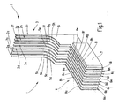
- FIG. 1 illustrates a module 1 intended for use in a stitch forming machine. It has several tools 2. Each individual tool 2a, 2b, 2c, 2d, 2e, 2f, 2g, 2h, 2i is precisely positioned with respect to the other tools 2.
- the tools 2 are in the in FIG. 1 specified embodiment normally open. However, it may also be in detail to knife, looper, Reetfinger, hooks, guide needles or other tools, as they are needed in textile machines, provided that they perform a common working movement in constant relative position.
- the tools 2 are identical to each other and have a plate-like basic shape. They are laterally aligned with each other in the module and held parallel to each other at a distance, so that they define a comb-like functional area 3 to these a holding portion 4 connects, which is used to attach the module 1 to a corresponding support, such as a bar of a stitch-forming machine , serves.
- the tools 2 each have a finger-like functional section 5a, 5b, 5c, 5d, 5e, 5f, 5g, 5h, 5i and a holding section 6a, 6b, 6c, 6d, 6e, 6f, 6g, 6h, 6i.
- the functional portions 5 are integrally connected to the holding portions 6, respectively.
- the tools 2 are formed by stampings.
- the holding sections 6 are connected to each other via a plastic body 7, which connects the tools 2 inextricably linked.
- the plastic body 7 is designed so that it passes through all the holding sections 6, wherein it leaves the edge 8a, 8b, 8c, 8d, 8e, 8f, 8g, 8h, 8i but at least partially free, ie not reached.
- the narrow edges 8a, 8b, 8c, 8d, 8e, 8f, 8g, 8h, 8i form contact surfaces for positioning the tools of a module on a bar.
- the contact surfaces lie in a common plane and thus together form the (subdivided) contact surface of the holding region 4.
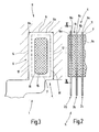
- the structure of the holding portion 4 is in particular from the FIGS. 2 and 3 out.
- FIG. 2 the plastic body 7 and the tool 2a, 2b and 2c are illustrated.
- the edges 8a, 8b, 8c lie in the common plane E, to, as FIG. 3 illustrated to abut a flat surface 9 of a schematically indicated bar 11.
- These are also arranged in a respective common plane and are located on contact surfaces 12, 14 of the bar 11 at.
- the approximately rectangular in side view holding portion 6a has a preferably also approximately rectangular central recess 15 in the form of an elongated opening which is surrounded by an edge 16. This includes with the outer edge 8a a strip 17 preferably a constant width.
- the plastic body 7 extends through the recess 15 and engages over the edge 16 of the opening 15 in each case on both flat sides.
- the strip 17 is thereby approximately half sunk into the plastic body 7.
- the plastic body 7 has an approximately rectangular cross section, so that the gap 18 extends along the entire edge 8 of the holding portion 6a and 6b. This applies to all other holding sections 6 accordingly.
- FIGS. 4 and 5 illustrate a modified embodiment of the module 1. As far as no separate explanations are given below, this module agrees with the module Figure 1 to 3 match. Reference is made to the above description with reference to the same reference numerals.
- the module according to the FIGS. 4 and 5 in its holding portion 4 on a plastic body 7, which comprises the holding portions 6 not at a central opening but at its respective edge 8a, 8b, 8c, 8d, 8e, 8f, 8g, 8h, 8i.
- the plastic body 7 extends to the contact surfaces 12, 14, ie its outer surfaces 21, 22 are aligned with edge portions 23, 24, 25, 26 of the holding sections 6.
- edge portions 23, 24 and 25, 26 are each recesses 27, 28 provided in the form of indentations, which may for example have a rectangular outline and are open-edged.
- the recesses 27, 28 are filled by corresponding parts of the plastic body 7, which otherwise covers the flat sides of the holding portions 6 substantially. On the narrow side, interspaces 18 can again remain between the holding sections 6 in order to favor the positioning in the bar 11.
- the holding portions 6 are held in the plastic body 7 both positive and cohesively by the adhesion between the base material of the plastic body 7 and the metal of the holding portions 6.
- the plastic body 7 can also protrude beyond the planes defined by the edge sections 23, 24 and 25, 26, so that it does not touch the contact surfaces 12, 14. However, it can also be very slightly, for example, a few hundredths of a millimeter over these defined by the edge portions 23, 24 and 25, 26 levels protruding to support a resilient clamping action thanks to its inherent elasticity.
- two partial bodies 7a, 7b may also be provided which, for example, abut one another at a center line 29, are connected to one another or here define a gap with one another.
- the plastic body 7a, 7b may be prefabricated and attached to the holding sections 6 in an assembly process. A fixation can be done by heat, by adhesive or by friction.
- the plastic body 7 may be integrally formed or consist of two parts which are pushed from the long narrow sides of the holding portions 6 ago on this.
- the fixation can be cohesively by adhesive or by friction. The latter has the advantage of demountability.
- edge 8 of the module after FIGS. 2 and 3 be provided with one or more recesses to reduce the contact area between the edge 8 and the abutment surfaces 9, 12, 14
- the holding portions 6 of the embodiments can after FIGS. 4 to 7 be provided with openings through which the plastic body 7 extends. This allows an even more intimate connection between the plastic and the tools 2 can be achieved.
- a module for textile machines has a plurality of tools 2 with holding sections 6. These are taken in a plastic body 7, the or the holding portions 6 at one or more recesses 15, 27, 28 or. It serves for the correct fixing of the tools 2 in relation to each other.
Description
In maschenbildenden Maschinen oder anderen Strickmaschinen kommen häufig Module zum Einsatz, die eine Gruppe spezieller Werkzeuge halten. Solche Module sind häufig als Gruppe in größerer Zahl auf einem Träger, einer so genannten Barre, befestigt und führen gemeinsam eine Arbeitsbewegung, beispielsweise eine hin- und hergehende Bewegung aus. Daraus ergeben sich Anforderungen an die Module, die bislang nicht oder nicht zur vollen Zufriedenheit gelöst sind. Solche Module müssen die einzelnen Werkzeuge in Bezug auf die Barre, auf andere Werkzeuge die zur Zusammenarbeit benötigt werden, sowie in Bezug aufeinander präzise halten. Die Präzision der Positionierung der einzelnen Werkzeuge ist insbesondere bei feinen Teilungen, d.h. bei geringen Werkzeugabständen für die ordnungsgemäße Funktion der Werkzeuge von Bedeutung. Dies gilt auch im Hinblick auf die exakte Positionierung der Werkzeuge zur Barre und anderen Werkzeugen.In knitting machines or other knitting machines modules are often used which hold a group of special tools. Such modules are often mounted as a group in larger numbers on a support, a so-called bar, and perform together a working movement, such as a reciprocating motion. This results in requirements for the modules that have not been solved or not to the full satisfaction. Such modules must precisely hold the individual tools with respect to the bar, other tools needed for cooperation, and with respect to one another. The precision of the positioning of the individual tools is particularly in fine divisions, i. at small tool intervals for the proper functioning of the tools of importance. This also applies to the exact positioning of the tools to Barre and other tools.
Soll die Textilmaschine eine hohe Arbeitsgeschwindigkeit erreichen, ist es zu wünschen, dass die Module eine möglichst geringe Masse aufweisen, um die Beschleunigungs- und Bremskräfte bei der Ausführung der hin- und hergehenden Bewegung nicht zu groß werden zu lassen. Dabei muss die präzise Lagerung der Werkzeuge bei aller Gewichtsersparnis jedoch gewahrt bleiben. Werkzeuge, die in der genannten Art zu Modulen zusammengefasst werden, sind beispielsweise so genannte Schließer, Legenadeln, Messer, Looper, Reetfinger, Haken und andere Werkzeuge, die an dem Modul zu einem kammartigen Gebilde zusammengefasst sind.If the textile machine is to achieve a high operating speed, it is desirable that the modules have as small a mass as possible in order not to let the acceleration and braking forces become too great during the execution of the reciprocating movement. However, the precise storage of the tools must be maintained with all weight savings. Tools that are summarized in modules in the aforementioned type, for example, so-called closers, guide needles, knives, looper, Reetfinger, hooks and others Tools that are combined on the module to a comb-like structure.
Aus der
Wird ein solches Gebilde an einer Barre befestigt, kann es wegen der Flexibilität der Klebebänder zu Problemen kommen. Außerdem ist der genaue Bezug zwischen den einzelnen Zinken und der Barre über die Klebebänder zu vermitteln.If such a structure attached to a bar, it may cause problems because of the flexibility of the tapes. In addition, the exact relationship between the individual prongs and the bar over the tapes to convey.
Aus der
Bei der Herstellung eines Pakets aus einzelnen Werkzeugen ist es bei dieser Vorgehensweise schwierig, hohen Genauigkeitsanforderungen zu entsprechen, insbesondere wenn es sich um kleine Werkzeuge handelt.In making a package of individual tools, this approach makes it difficult to meet high accuracy requirements, especially when dealing with small tools.
Aus der
Auch bei diesem Aufbau können sich Genauigkeitsprobleme ergeben.Even with this structure, accuracy problems can arise.
Aus der
Bei einer weiteren, aus dieser Druckschrift hervorgehenden Ausführungsform wird die Fassung durch einen einstückigen, plattenförmigen Körper aus Kunststoff gebildet, der an einem Ende beidseitig mit Rippen versehen ist, zwischen denen die drahtförmigen Enden der Lochnadeln befestigt sind.In another, resulting from this document embodiment, the socket is formed by a one-piece, plate-shaped body made of plastic, which is provided on both sides with ribs at one end, between which the wire-shaped ends of the hole needles are attached.
Die Herstellung einer solchen Lochnadelfassung ist mit einem nicht zu unterschätzenden Aufwand verbunden.The production of such a Lochnadelfassung is associated with a not to be underestimated effort.
Aus der
Aus der
Lochnadeln aus Kunststoff sind nur für wenige Anwendungszwecke wirklich geeignet. In der Regel werden aus Metall bestehende Werkzeuge bevorzugt.Plastic puncture needles are really only suitable for a few applications. As a rule, tools made of metal are preferred.
Aus der
Davon ausgehend ist es Aufgabe der Erfindung, ein Modul für Textilmaschinen zu schaffen, das hohen Genauigkeitsanforderungen genügt, ein geringes Gewicht aufweist und auf rationelle Weise herzustellen ist.On this basis, it is an object of the invention to provide a module for textile machines, which meets high accuracy requirements, has a low weight and is to produce in a rational manner.
Diese Aufgabe wird durch das Modul mit den Merkmalen des Patentanspruchs 1 gelöst:
- Das erfindungsgemäße Modul weist mehrere Werkzeuge auf, die jeweils einen Funktionsabschnitt und einen Halteabschnitt aufweisen. Der Halteabschnitt dient der Positionierung des Werkzeugs an einem Halter, d.h. beispielsweise einer Barre. Er weist wenigstens eine Ausnehmung auf, die von einem Kunststoffkörper durchsetzt ist. Dieser bindet alle Werkzeuge zu einem Modul zusammen, der nur im Ganzen gehandhabt werden kann. Eine metallische Verbindung zwischen den Halteabschnitten besteht nicht. Es besteht auch sonst keine metallische Verbindung zwischen den Werkzeugen. Der Kunststoffkörper weist ein wesentlich geringeres Gewicht auf als ein entsprechender alternativ verwendbarer Metallkörper. Außerdem kann er die einzelnen Werkzeuge dauerhaft und präzise in Bezug aufeinander halten. Indem er die Ausnehmung des Halteabschnitts durchgreift lässt sich ein Formschluss erzielen, so dass das einzelne Werkzeug nicht ausschließlich auf die Haftung zwischen Kunststoff und Metall angewiesen ist, wenn die Werkzeuge aus Metall bestehen.
- The module according to the invention has a plurality of tools, each having a functional portion and a holding portion. The holding section serves to position the tool on a holder, ie for example a bar. He has at least one recess which is penetrated by a plastic body. This combines all the tools into a module that can only be handled as a whole. A metallic connection between the holding sections does not exist. There is otherwise no metallic connection between the tools. The plastic body has a much lower weight than a corresponding alternatively usable metal body. In addition, he can keep the individual tools permanently and precisely in relation to each other. By passing through the recess of the holding portion can achieve a positive connection, so that the individual tool is not dependent solely on the adhesion between plastic and metal when the tools are made of metal.
Vorzugsweise weist der Halteabschnitt eines Werkzeugs wenigstens eine Anlagefläche auf, die frei zu Tage liegt. Diese Anlagefläche(n) kann (können) zur Positionierung des Moduls an einer Barre genutzt werden. Die Werkzeuge sind damit direkt, d.h. ohne Zwischenlage irgendwelcher anderen Elemente, an der Barre gelagert, so dass bei präziser Ausbildung der Barre und präziser Ausbildung der einzelnen Werkzeuge auch eine präzise Positionierung der Werkzeuge an der Barre erreicht wird. Dies gilt insbesondere, wenn die Anlageflächen der Werkzeuge in einer gemeinsamen Ebene liegen. Dies kann beispielsweise dadurch erreicht werden, dass alle Werkzeuge zueinander parallel sowie miteinander fluchtend und im Abstand zueinander ausgerichtet sind.The holding section of a tool preferably has at least one contact surface which is exposed. This contact surface (s) can (can) be used to position the module on a bar. The tools are thus directly, ie stored without interposition of any other elements on the bar, so that with precise formation of the bar and precise training of the individual tools, a precise positioning of the tools is achieved on the bar. This is especially true when the contact surfaces of the tools lie in a common plane. This can be achieved, for example, in that all the tools are aligned parallel to one another and aligned with one another and at a distance from one another.
Der Halteabschnitt und der Funktionsabschnitt jedes Werkzeugs sind vorzugsweise einstückig miteinander verbunden. Beispielsweise können die Werkzeuge Stanzteile oder anderweitige Metallteile sein. Die einstückige Ausbildung der Werkzeuge vermeidet Genauigkeitsprobleme bei der Relativpositionierung von Halteabschnitt und Funktionsabschnitt.The holding portion and the functional portion of each tool are preferably integrally connected with each other. For example, the tools may be stampings or other metal parts. The one-piece design of the tools avoids accuracy problems in the relative positioning of the holding section and functional section.
Bei einer bevorzugten Ausführungsform sind die Werkzeuge untereinander ausschließlich über den Kunststoffkörper verbunden. Es fehlen jegliche anderen Verbindungsmittel. Dies schafft einen einfachen Aufbau sowie die Möglichkeit einer einfachen Herstellung.In a preferred embodiment, the tools are interconnected exclusively via the plastic body. It lacks any other means of connection. This creates a simple structure and the possibility of simple production.
Der Kunststoffkörper steht mit den Werkzeugen vorzugsweise in formschlüssigem Eingriff sowie alternativ oder zusätzlich in stoffschlüssiger Verbindung. Dies kann erreicht werden, indem der Halteabschnitt mit ein oder mehreren Ausnehmungen versehen ist, die sich im Wesentlichen in seinem zentralen Bereich befinden. Durchsetzt der Kunststoffkörper diese Ausnehmung und übergreift er dabei den Rand der Ausnehmung hält der Kunststoffkörper die Werkzeuge form- und stoffschlüssig. Der Kunststoffkörper kann als Spritzgusskörper hergestellt werden. Dabei kann die Spritzgussform so ausgebildet sein, dass die einzelnen Werkzeuge, insbesondere an ihren Lagerungsabschnitten in der Spritzgussform so lange unverrückbar gehalten bleiben, bis der Kunststoffkörper fertig gestellt ist. Es lässt sich damit eine sehr genaue Positionierung der Werkzeuge erreichen. Dies gilt insbesondere, wenn der Kunststoffkörper den äußeren Rand der Halteabschnitte nicht erreicht, so dass der gesamte oder nahezu der gesamte Rand der Halteabschnitte frei bleibt. Hier können die Halteabschnitte während der Herstellung des Kunststoffkörpers gefasst und positioniert werden. Alternativ kann es genügen, die Halteabschnitte wenigstens an zwei gegenüber liegenden Stellen ihres Randes zu fassen und zu halten.The plastic body is preferably in positive engagement with the tools as well as alternatively or additionally in cohesive connection. This can be achieved by providing the holding section with one or more recesses located substantially in its central area. The plastic body penetrates this recess and, in so doing, it engages over the edge of the recess, holding the plastic body in a positive and cohesive manner. The plastic body can be produced as an injection molded body. In this case, the injection mold may be formed so that the individual tools, especially at their storage sections in the injection mold remain immovable until the plastic body is completed. It can thus achieve a very accurate positioning of the tools. This applies in particular if the plastic body does not reach the outer edge of the holding sections, so that the entire or almost the entire edge of the holding sections remains free. Here, the holding sections can be taken and positioned during the production of the plastic body. Alternatively, it may be enough to grasp and hold the holding portions at least at two opposite points of their edge.
Bei einer alternativen Ausführungsform sind ein oder mehrere randoffene Ausnehmungen für den Kunststoffkörper vorgesehen. Diese Ausführungsform hat den Vorzug, dass der Kunststoffkörper separat hergestellt werden kann, wobei die Halteabschnitte der einzelnen Werkzeuge dann beispielsweise in vorgeformte Schlitze des Kunststoffkörpers eingeschoben werden. Der durchgehende Teil des Kunststoffkörpers gelangt dabei in die Ausnehmung und bildet die Verbindung zwischen den Werkzeugen. Dabei ist es vorteilhaft, wenn zwei an einander gegenüber liegenden Rändern des Halteabschnitts vorgesehene Ausnehmungen die Aufnahmen für Kunststoffkörper bilden. Auf diese Weise wird ein kompaktes Modul erhalten.In an alternative embodiment, one or more open-edged recesses are provided for the plastic body. This embodiment has the advantage that the plastic body can be manufactured separately, wherein the holding portions of the individual tools are then inserted, for example, in preformed slots of the plastic body. The continuous part of the plastic body passes into the recess and forms the connection between the tools. It is advantageous if two provided on mutually opposite edges of the holding portion recesses form the receptacles for plastic body. In this way, a compact module is obtained.
Bei einer weiter abgewandelten Ausführungsform kann der Kunststoffkörper eine Anlagefläche aufweisen. Dies kann vorteilhaft sein, wenn die speziellen Kunststoffeigenschaften, die beispielsweise in seiner inneren Dämpfung oder seiner Elastizität liegen, zwischen der Barre und den Werkzeugen wirksam werden sollen. Dabei ist es auch möglich, die Anlageflächen der Halteabschnitte mit der Anlagefläche des Kunststoffkörpers zu kombinieren, so dass die Halteabschnitte an einer Stelle selbst an der Barre anliegen, während sie an anderer Stelle mittelbar über den Kunststoffkörper an der Barre anliegen.In a further modified embodiment, the plastic body may have a contact surface. This can be advantageous if the special plastic properties, which are for example in its internal damping or its elasticity, between the bar and the tools to be effective. It is also possible to combine the contact surfaces of the holding portions with the contact surface of the plastic body, so that the holding portions lie at one point even on the bar, while they rest indirectly elsewhere on the plastic body on the bar.
Der Kunststoffkörper kann aus einem thermoplastischen Kunststoff, aus einem aushärtenden Kunststoff, aus einem ein- oder mehrkomponenten Kunststoff sowie aus einem faserverstärkten Kunststoff aufgebaut sein. Dies hängt vom gewünschten Fertigungsverfahren und vom zu erzielenden Ergebnis ab.The plastic body may be constructed of a thermoplastic, of a thermosetting plastic, of a single- or multi-component plastic and of a fiber-reinforced plastic. This depends on the desired manufacturing process and on the result to be achieved.
Weitere Einzelheiten vorteilhafter Ausführungsformen der Erfindung ergeben sich aus der Zeichnung, der Beschreibung und aus Unteransprüchen. In der Zeichnung sind Ausführungsbeispiele der Erfindung veranschaulicht. Es zeigen:
-
Figur 1 -
Figur 2Modul nach Figur 1 in ausschnittsweiser Draufsicht, -
Figur 3 dasModul nach Figur 2 , geschnitten entlang der Linie III-III, -
Figur 4 -
Figur 5 dasModul nach Figur 4 , geschnitten entlang der Linie V-V, -
Figur 6 -
Figur 7Modul nach Figur 6 , geschnitten entlang der Linie VII-VII.
-
FIG. 1 an inventive module in a perspective, schematic representation, -
FIG. 2 the module afterFIG. 1 in a sectional plan view, -
FIG. 3 the module afterFIG. 2 , cut along the line III-III, -
FIG. 4 a modified embodiment of the module in a sectional plan view, -
FIG. 5 the module afterFIG. 4 , cut along the line VV, -
FIG. 6 a further modified embodiment of the module in a sectional plan view and -
FIG. 7 the module afterFIG. 6 , cut along the line VII-VII.
In
Die Werkzeuge 2 sind untereinander gleich ausgebildet und weisen eine plattenartige Grundform auf. Sie sind in dem Modul seitlich miteinander fluchtend und im Abstand parallel zueinander gehalten, so dass sie einen kammartigen Funktionsbereich 3 festlegen An diesen schließt sich ein Haltebereich 4 an, der zur Befestigung des Moduls 1 an einem entsprechenden Träger, wie beispielsweise einer Barre einer maschenbildenden Maschine, dient. Die Werkzeuge 2 weisen jeweils einen fingerartigen Funktionsabschnitt 5a, 5b, 5c, 5d, 5e, 5f, 5g, 5h, 5i und einen Halteabschnitt 6a, 6b, 6c, 6d, 6e, 6f, 6g, 6h, 6i auf. Die Funktionsabschnitte 5 sind mit den Halteabschnitten 6 jeweils einstückig verbunden. Beispielsweise sind die Werkzeuge 2 durch Stanzteile gebildet.The
Die Halteabschnitte 6 sind untereinander über einen Kunststoffkörper 7 verbunden, der die Werkzeuge 2 unlösbar miteinander verbindet. Der Kunststoffkörper 7 ist dabei so ausgebildet, dass er alle Halteabschnitte 6 durchsetzt, wobei er deren Rand 8a, 8b, 8c, 8d, 8e, 8f, 8g, 8h, 8i jedoch wenigstens abschnittsweise frei lässt, d.h. nicht erreicht. Dadurch bilden die schmalen Ränder 8a, 8b, 8c, 8d, 8e, 8f, 8g, 8h, 8i Anlageflächen zur Positionierung der Werkzeuge eines Moduls an einer Barre. Die Anlageflächen liegen dabei in einer gemeinsamen Ebene und bilden somit gemeinsam die (untergliederte) Anlagefläche des Haltebereichs 4.The holding
Der Aufbau des Haltebereichs 4 geht insbesondere aus den
Der Kunststoffkörper 7 erstreckt sich durch die Ausnehmung 15 hindurch und übergreift den Rand 16 der Öffnung 15 jeweils an beiden Flachseiten. Der Streifen 17 ist dadurch etwa zur Hälfte in den Kunststoffkörper 7 eingesenkt. Wie insbesondere aus
Wird der Haltebereich 4, wie
Die
Im Unterschied zu dem vorbeschriebenen Modul weist das Modul nach den
An Stelle eines einzigen kompakten Kunststoffkörpers 7 können auch zwei Teilkörper 7a, 7b vorgesehen werden, die beispielsweise bei einer Mittellinie 29 aneinander stoßen, miteinander verbunden sind oder hier einen Spalt miteinander begrenzen. Die Kunststoffkörper 7a, 7b können vorgefertigt sein und in einem Montagevorgang an die Halteabschnitte 6 angesetzt werden. Eine Fixierung kann durch Wärme, durch Klebstoff oder reibschlüssig erfolgen.Instead of a single compact
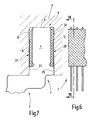
Eine weitere Ausführungsform der Erfindung ist in den
Bei dem Modul 1 nachden Figuren 6 und 7 sind dieAusnehmungen Randabschnitte der Halteabschnitte 6 entfallen. Es verbleiben dieRandabschnitte mit den Anlageflächen Halteabschnitte 6 mit ihrer Schmalseite in direkter Anlagemit der Anlagefläche 9. Somitliegen die Halteabschnitte 6 wie bei allen vorstehend beschriebenen Ausführungsformen an drei Seiten desHaltebereichs 4 frei zu Tage und zwar an den beiden einander gegenüber liegenden Flachseiten des Halteabschnitts 4 sowie an dervon den Werkzeugen 2 abliegenden Schmalseite. Darüber hinaus erstreckt sich der Kunststoffkörper 7 durch dieAusnehmungen dem Kunststoffkörper 7Anlageflächen die Randabschnitte Moduls 1 nachFigur 5 ersetzen.Die Anlageflächen Flachseiten des Haltebereichs 4 in unmittelbarer Nachbarschaft zu dessen Schmalseite angeordnet.Die Anlageflächen kann das Modul 1 auf diese Weise durch direkte Metall/Metall-Anlage zwischenden Halteabschnitte 6 und derBarre 1 präzise gelagert werden. Durch die dem Kunststoff inhärente Nachgiebigkeit, die durch dieAusbildung der Anlageflächen Barre 11. Wird der Kunststoff als nachgiebig angesehen, bilden dieRandabschnitte Haltebereichs 4, eine Dreipunktanlage.
- In the
module 1 after theFIGS. 6 and 7 are therecesses edge portions sections 6 omitted. There remain theedge portions sections 6 are free with their narrow side in direct contact with thecontact surface 9. Thus, the holdingsections 6 as in all the embodiments described above on three sides of the holdingportion 4 to day and on the two opposite flat sides of the holdingportion 4 and the off thetools 2 narrow side. In addition, theplastic body 7 extends through therecesses plastic body 7 contact surfaces 31, 32 are formed, theedge portions module 1 afterFIG. 5 replace. The contact surfaces 31, 32 are arranged on the flat sides of the holdingregion 4 in the immediate vicinity of its narrow side. The contact surfaces 31, 32 are slightly above the remainingplastic body 7. For example, if a tough elastic plastic is chosen, which has inherent spring and damping properties, themodule 1 can be precisely stored in this way by direct metal / metal system between the holdingsections 6 and theBarre 1. Due to the plastic inherent resilience, which can be used by the formation of the contact surfaces 31, 32 as a narrow strip to a particular extent, there is also a high tolerance insensitivity of themodule 1 against theBarre 11. If the plastic considered compliant, form theEdge portions portion 4, a three-point system.
Wie bei dem vorstehend beschriebenen Ausführungsbeispiel kann der Kunststoffkörper 7 einstückig ausgebildet sein oder aus zwei Teilen bestehen, die von den langen Schmalseiten der Halteabschnitte 6 her auf diese aufgeschoben sind. Die Fixierung kann stoffschlüssig durch Klebstoff oder durch Reibschluss erfolgen. Letzteres hat den Vorzug der Demontierbarkeit.As in the embodiment described above, the
Weitere vorteilhafte Ausführungsformen und Abwandlungen sind möglich. Beispielsweise kann der Rand 8 des Moduls nach
Ein Modul für Textilmaschinen weist mehrere Werkzeuge 2 mit Halteabschnitten 6 auf. Diese sind in einem Kunststoffkörper 7 gefasst, der die Halteabschnitte 6 bei einer oder mehreren Ausnehmungen 15, 27, 28 aus- oder umgreift. Er dient der lagerichtigen Fixierung der Werkzeuge 2 in Bezug aufeinander. Die Positionierung der Werkzeuge 2 in Bezug auf eine Barre 11 erfolgt jedoch durch direkte Anlage zwischen den Halteabschnitten 6 und der Barre 11. Durch die Ausfüllung der zwischen den Halteabschnitten vorhandenen spaltförmigen Zwischenräume mit Kunststoff wird ein kompakter, dabei aber leichter Haltebereich 4 für das Modul 1 erhalten.A module for textile machines has a plurality of
- 11
- Modulmodule
- 22
- WerkzeugeTools
- 2a bis 2i2a to 2i
- WerkzeugTool
- 33
- Funktionsbereichfunctional area
- 44
- Haltebereichholding area
- 55
- Funktionsabschnittefunctional sections
- 5a bis 5i5a to 5i
- Funktionsabschnittfunction section
- 66
- Halteabschnitteholding portions
- 6a bis 6i6a to 6i
- Halteabschnittholding section
- 7, 7a, 7b7, 7a, 7b
- KunststoffkörperPlastic body
- 8a bis 8i8a to 8i
- Randedge
- 99
- Anlageflächecontact surface
- 1111
- Barrebar
- 12, 1412, 14
- Anlageflächecontact surface
- 1515
- Ausnehmungrecess
- 1616
- Randedge
- 1717
- Streifenstrip
- 1818
- Zwischenraumgap
- 21, 2221, 22
- Außenflächenexterior surfaces
- 23, 24, 25, 2623, 24, 25, 26
- Randabschnitteedge sections
- 27, 2827, 28
- Ausnehmungenrecesses
- 2929
- Mittelliniecenter line
- 31, 3231, 32
- Anlageflächencontact surfaces
- Ee
- Ebenelevel
Claims (18)
- Module (1) for textile machines, in particular stitch-forming machines,
with a plurality of metal tools (2), which have function sections (5) and holding sections (6),
wherein the holding sections (6) respectively have at least one recess (15, 27, 28), through which a plastic body (7) passes,
characterised in that
the plastic body (7) is an injection moulding, which passes through the recess (15, 27, 28) and engages over its edge. - Module according to claim 1, characterised in that the holding section (6a) of at least one tool (2a) has at least one abutment surface (8a), which lies freely exposed.
- Module according to claim 1, characterised in that the tools (2) are held parallel to one another, in alignment with one another and spaced from one another.
- Module according to claim 1, characterised in that the tools (2) are configured uniformly.
- Module according to claim 1, characterised in that the holding sections (6) and the function sections (5) are respectively connected to one another in one piece.
- Module according to claim 1, characterised in that the tools (2) are connected to one another by the plastic body (7).
- Module according to claim 1, characterised in that the tools (2) are connected to one another solely by means of the plastic body (7).
- Module according to claim 1, characterised in that the plastic body (7) engages positively with the tools (2).
- Module according to claim 1, characterised in that the plastic body (7) is integrally connected to the tools (2).
- Module according to claim 1, characterised in that the recess (15, 27, 28) respectively provided in the holding sections (6) passes centrally through the holding sections (6).
- Module according to claim 10, characterised in that the recess (15) has a closed edge (16) adjoining its entire periphery.
- Module according to claim 1, characterised in that the recess (27, 28) is open-edged.
- Module according to claim 1, characterised in that open-edged recesses (27, 28) are configured on two opposite sides of the holding section (6).
- Module according to claim 1, characterised in that the plastic body (7) fills the entire recess (15) and projects over its edge (16), but at least in some locations does not reach the outer periphery of the holding section (6).
- Module according to claim 1, characterised in that the plastic body (7) projects beyond the holding sections (6) of the tools (2) at least at one location.
- Module according to claim 1, characterised in that at least one abutment surface (31) is configured on the plastic body (7).
- Module according to claim 1, characterised in that abutment surfaces (24, 25, 31, 32) are configured both on the holding sections (6) and on the plastic body (7).
- Module according to claim 1, characterised in that the plastic body (7) is made from a fibre-reinforced plastic.
Applications Claiming Priority (3)
| Application Number | Priority Date | Filing Date | Title |
|---|---|---|---|
| DE10227532 | 2002-06-20 | ||
| DE10227532A DE10227532B4 (en) | 2002-06-20 | 2002-06-20 | Module for textile machines, in particular mesh-forming machines |
| PCT/DE2003/001693 WO2004001113A1 (en) | 2002-06-20 | 2003-05-24 | Module for textile machines, especially stitch-forming machines |
Publications (2)
| Publication Number | Publication Date |
|---|---|
| EP1518015A1 EP1518015A1 (en) | 2005-03-30 |
| EP1518015B1 true EP1518015B1 (en) | 2009-06-03 |
Family
ID=29795833
Family Applications (1)
| Application Number | Title | Priority Date | Filing Date |
|---|---|---|---|
| EP03760549A Expired - Lifetime EP1518015B1 (en) | 2002-06-20 | 2003-05-24 | Module for textile machines, especially stitch-forming machines |
Country Status (9)
| Country | Link |
|---|---|
| US (1) | US7055347B2 (en) |
| EP (1) | EP1518015B1 (en) |
| JP (1) | JP4608314B2 (en) |
| KR (1) | KR100644742B1 (en) |
| CN (1) | CN100451201C (en) |
| AU (1) | AU2003232158A1 (en) |
| DE (2) | DE10227532B4 (en) |
| ES (1) | ES2327403T3 (en) |
| WO (1) | WO2004001113A1 (en) |
Cited By (1)
| Publication number | Priority date | Publication date | Assignee | Title |
|---|---|---|---|---|
| US11585029B2 (en) | 2021-02-16 | 2023-02-21 | Card-Monroe Corp. | Tufting maching and method of tufting |
Families Citing this family (8)
| Publication number | Priority date | Publication date | Assignee | Title |
|---|---|---|---|---|
| DE502006002189D1 (en) * | 2006-02-02 | 2009-01-08 | Groz Beckert Kg | System part for a knitting system and handling method |
| EP1816247B1 (en) | 2006-02-02 | 2008-11-26 | Groz-Beckert KG | System component for a knitting system, and handling process |
| DE502008001881D1 (en) * | 2008-01-12 | 2011-01-05 | Stoll H Gmbh & Co Kg | Cassette of a knitting machine |
| DE102009010316B4 (en) * | 2009-02-24 | 2016-11-10 | Karl Mayer Textilmaschinenfabrik Gmbh | Method for producing a knitting tool holder |
| CN104131409A (en) * | 2014-07-12 | 2014-11-05 | 常德纺织机械有限公司 | Looping tool for warp knitting machine |
| EP3067451A1 (en) * | 2015-03-10 | 2016-09-14 | Groz-Beckert KG | Method and device for producing a weaving reed and weaving reed |
| ES2712737T3 (en) | 2016-05-04 | 2019-05-14 | Groz Beckert Kg | Textile tool module and textile machine with a textile tool module |
| EP3792382B1 (en) * | 2019-09-10 | 2024-02-07 | Groz-Beckert KG | Reed with plurality of strips |
Family Cites Families (15)
| Publication number | Priority date | Publication date | Assignee | Title |
|---|---|---|---|---|
| US2682163A (en) * | 1949-11-17 | 1954-06-29 | Aaron S Staff | Trick plate |
| US3369379A (en) | 1965-05-28 | 1968-02-20 | Torrington Co | Jack for automatic knitting machine |
| DE2110916A1 (en) * | 1970-03-17 | 1971-10-14 | Vyzk Ustav Pletarzsky | Working element of a knitting machine with at least one needle butt |
| US3823581A (en) * | 1973-02-02 | 1974-07-16 | C Russo | Knitting machine needle holder |
| DE8536352U1 (en) | 1985-12-23 | 1986-04-03 | Dengler, Franz, 8502 Zirndorf | Hole needle segment for crochet and Raschel machines |
| DE4224490C2 (en) * | 1992-04-10 | 1994-06-16 | Heguplast V Gutwald Kg Kunstst | Process for producing a blank or needle bar and corresponding tool |
| DE4406622C2 (en) * | 1994-03-01 | 1996-01-11 | Erwin Giegerich | Needle holder |
| DE19618368B4 (en) * | 1996-05-08 | 2005-11-24 | Karl Mayer Textilmaschinenfabrik Gmbh | Arrangement of thread guide elements of a warp or knitting machine and a carrier |
| DE19753590C1 (en) * | 1997-12-03 | 1999-05-12 | Mayer Textilmaschf | Warp knitter needle carrier segment |
| DE19757962C2 (en) | 1997-12-24 | 2003-05-28 | Saxonia Umformtechnik Gmbh | pipe connection |
| DE19803474C1 (en) | 1998-01-29 | 1999-09-23 | Saxonia Umformtechnik Gmbh | Method of making comb-like structures |
| ITTO980484A1 (en) * | 1998-06-04 | 1999-12-04 | Matrix Spa | MODULAR DEVICE FOR PIEZOELECTRIC SELECTION OF CONTROL ELEMENTS, FOR EXAMPLE THE NEEDLES OF A TEXTILE MACHINE. |
| DE19854191B4 (en) * | 1998-11-24 | 2008-02-21 | Saxonia Textile Parts Gmbh | Method for connecting needle packs |
| DE19920673C2 (en) * | 1999-05-05 | 2003-10-16 | Kern & Liebers | Board segment |
| DE10325671B4 (en) * | 2003-06-06 | 2007-03-01 | Groz-Beckert Kg | Shipping unit of elongated system parts, in particular needles, for stitch-forming machines |
-
2002
- 2002-06-20 DE DE10227532A patent/DE10227532B4/en not_active Expired - Fee Related
-
2003
- 2003-05-24 EP EP03760549A patent/EP1518015B1/en not_active Expired - Lifetime
- 2003-05-24 AU AU2003232158A patent/AU2003232158A1/en not_active Abandoned
- 2003-05-24 DE DE50311578T patent/DE50311578D1/en not_active Expired - Lifetime
- 2003-05-24 WO PCT/DE2003/001693 patent/WO2004001113A1/en active Application Filing
- 2003-05-24 JP JP2004514542A patent/JP4608314B2/en not_active Expired - Lifetime
- 2003-05-24 KR KR1020047020391A patent/KR100644742B1/en active IP Right Grant
- 2003-05-24 US US10/516,130 patent/US7055347B2/en not_active Expired - Lifetime
- 2003-05-24 CN CNB038141973A patent/CN100451201C/en not_active Expired - Lifetime
- 2003-05-24 ES ES03760549T patent/ES2327403T3/en not_active Expired - Lifetime
Cited By (1)
| Publication number | Priority date | Publication date | Assignee | Title |
|---|---|---|---|---|
| US11585029B2 (en) | 2021-02-16 | 2023-02-21 | Card-Monroe Corp. | Tufting maching and method of tufting |
Also Published As
| Publication number | Publication date |
|---|---|
| DE50311578D1 (en) | 2009-07-16 |
| JP4608314B2 (en) | 2011-01-12 |
| KR100644742B1 (en) | 2006-11-14 |
| DE10227532B4 (en) | 2006-02-23 |
| US7055347B2 (en) | 2006-06-06 |
| AU2003232158A1 (en) | 2004-01-06 |
| ES2327403T3 (en) | 2009-10-29 |
| CN1662695A (en) | 2005-08-31 |
| WO2004001113A1 (en) | 2003-12-31 |
| DE10227532A1 (en) | 2004-05-19 |
| EP1518015A1 (en) | 2005-03-30 |
| US20050183467A1 (en) | 2005-08-25 |
| JP2005533936A (en) | 2005-11-10 |
| KR20050013211A (en) | 2005-02-03 |
| CN100451201C (en) | 2009-01-14 |
Similar Documents
| Publication | Publication Date | Title |
|---|---|---|
| DE4223642A1 (en) | TUFTING MACHINE WITH SELF-ALIGNING ADJUSTMENT MODULES | |
| EP1518015B1 (en) | Module for textile machines, especially stitch-forming machines | |
| DE4421388C2 (en) | Needle attachment device for knitting machines | |
| DE3727179C2 (en) | Method of making a loop former module | |
| DE102006004099B3 (en) | Knitting needle, especially for a warp knitting machine, comprises an attachment region whose front or rear side is wider than the opposite side | |
| DE3515854C2 (en) | Fastener assembly | |
| EP1988198B1 (en) | Tool set and bar for a warp knitting machine | |
| EP1816246B1 (en) | Take-off comb for flat or warp knitting machine | |
| EP1600543B1 (en) | Warp-knitting implement mounting bar | |
| DE102008033205A1 (en) | Component holder for fixing electrolytic capacitor at printed circuit board, has frame defining accommodating chamber for accommodating electronic component, and recesses displaceably arranged against each other in axial direction | |
| EP0662733B1 (en) | Contact spring arrangement | |
| EP0375843B1 (en) | Stamped knitting tool for textile machines, particularly for knitting machines | |
| EP0426994B1 (en) | Stamped knitting implement for textile machines | |
| DE19750055C2 (en) | Tile cutter | |
| DE1660790A1 (en) | Needle bed for needle felting machines | |
| DE19835500C1 (en) | Sewing machine attachment to cut buttonhole slits has tool section with anvil facing cutter with slit to hold anvil in number of positions | |
| EP2138617B1 (en) | Needle board for a needle machine | |
| DE2508616C3 (en) | Process for setting saw teeth and device for carrying out this process | |
| EP2072652A1 (en) | Module, in particular tufting module and method for manufacturing such a module | |
| DE2835186C2 (en) | Device for holding several knives for tufting machines | |
| WO1988003578A1 (en) | Holder for closely-spaced holed needles | |
| DE3323346A1 (en) | Process for manufacturing a plastics part and device for carrying out the process | |
| DE4406622C2 (en) | Needle holder | |
| DE2717718A1 (en) | NEEDLE ROD, IN PARTICULAR GILL ROD FOR TEXTILE MACHINERY | |
| DE1935359B2 (en) | DEVICE FOR PUNCHING A FREE GAP IN A CONTINUOUS ZIPPER |
Legal Events
| Date | Code | Title | Description |
|---|---|---|---|
| PUAI | Public reference made under article 153(3) epc to a published international application that has entered the european phase |
Free format text: ORIGINAL CODE: 0009012 |
|
| 17P | Request for examination filed |
Effective date: 20041020 |
|
| AK | Designated contracting states |
Kind code of ref document: A1 Designated state(s): AT BE BG CH CY CZ DE DK EE ES FI FR GB GR HU IE IT LI LU MC NL PT RO SE SI SK TR |
|
| AX | Request for extension of the european patent |
Extension state: AL LT LV MK |
|
| DAX | Request for extension of the european patent (deleted) | ||
| RBV | Designated contracting states (corrected) |
Designated state(s): DE ES FR GB IT |
|
| 17Q | First examination report despatched |
Effective date: 20060720 |
|
| GRAP | Despatch of communication of intention to grant a patent |
Free format text: ORIGINAL CODE: EPIDOSNIGR1 |
|
| GRAS | Grant fee paid |
Free format text: ORIGINAL CODE: EPIDOSNIGR3 |
|
| GRAA | (expected) grant |
Free format text: ORIGINAL CODE: 0009210 |
|
| AK | Designated contracting states |
Kind code of ref document: B1 Designated state(s): DE ES FR GB IT |
|
| REG | Reference to a national code |
Ref country code: GB Ref legal event code: FG4D Free format text: NOT ENGLISH |
|
| REF | Corresponds to: |
Ref document number: 50311578 Country of ref document: DE Date of ref document: 20090716 Kind code of ref document: P |
|
| REG | Reference to a national code |
Ref country code: ES Ref legal event code: FG2A Ref document number: 2327403 Country of ref document: ES Kind code of ref document: T3 |
|
| PLBE | No opposition filed within time limit |
Free format text: ORIGINAL CODE: 0009261 |
|
| STAA | Information on the status of an ep patent application or granted ep patent |
Free format text: STATUS: NO OPPOSITION FILED WITHIN TIME LIMIT |
|
| 26N | No opposition filed |
Effective date: 20100304 |
|
| REG | Reference to a national code |
Ref country code: FR Ref legal event code: PLFP Year of fee payment: 14 |
|
| REG | Reference to a national code |
Ref country code: FR Ref legal event code: PLFP Year of fee payment: 15 |
|
| REG | Reference to a national code |
Ref country code: FR Ref legal event code: PLFP Year of fee payment: 16 |
|
| PGFP | Annual fee paid to national office [announced via postgrant information from national office to epo] |
Ref country code: FR Payment date: 20180411 Year of fee payment: 16 |
|
| PG25 | Lapsed in a contracting state [announced via postgrant information from national office to epo] |
Ref country code: FR Free format text: LAPSE BECAUSE OF NON-PAYMENT OF DUE FEES Effective date: 20190531 |
|
| PGFP | Annual fee paid to national office [announced via postgrant information from national office to epo] |
Ref country code: IT Payment date: 20220412 Year of fee payment: 20 Ref country code: GB Payment date: 20220401 Year of fee payment: 20 Ref country code: ES Payment date: 20220603 Year of fee payment: 20 Ref country code: DE Payment date: 20220531 Year of fee payment: 20 |
|
| REG | Reference to a national code |
Ref country code: DE Ref legal event code: R071 Ref document number: 50311578 Country of ref document: DE |
|
| REG | Reference to a national code |
Ref country code: ES Ref legal event code: FD2A Effective date: 20230531 |
|
| REG | Reference to a national code |
Ref country code: GB Ref legal event code: PE20 Expiry date: 20230523 |
|
| PG25 | Lapsed in a contracting state [announced via postgrant information from national office to epo] |
Ref country code: ES Free format text: LAPSE BECAUSE OF EXPIRATION OF PROTECTION Effective date: 20230525 |
|
| PG25 | Lapsed in a contracting state [announced via postgrant information from national office to epo] |
Ref country code: GB Free format text: LAPSE BECAUSE OF EXPIRATION OF PROTECTION Effective date: 20230523 |