EP1517583A2 - Hearing aid for determination of the volume of the auditory canal and related adaptation method - Google Patents
Hearing aid for determination of the volume of the auditory canal and related adaptation method Download PDFInfo
- Publication number
- EP1517583A2 EP1517583A2 EP04021501A EP04021501A EP1517583A2 EP 1517583 A2 EP1517583 A2 EP 1517583A2 EP 04021501 A EP04021501 A EP 04021501A EP 04021501 A EP04021501 A EP 04021501A EP 1517583 A2 EP1517583 A2 EP 1517583A2
- Authority
- EP
- European Patent Office
- Prior art keywords
- hearing aid
- electrical input
- impedance
- input impedance
- mechanical resonance
- Prior art date
- Legal status (The legal status is an assumption and is not a legal conclusion. Google has not performed a legal analysis and makes no representation as to the accuracy of the status listed.)
- Granted
Links
Images
Classifications
-
- H—ELECTRICITY
- H04—ELECTRIC COMMUNICATION TECHNIQUE
- H04R—LOUDSPEAKERS, MICROPHONES, GRAMOPHONE PICK-UPS OR LIKE ACOUSTIC ELECTROMECHANICAL TRANSDUCERS; DEAF-AID SETS; PUBLIC ADDRESS SYSTEMS
- H04R25/00—Deaf-aid sets, i.e. electro-acoustic or electro-mechanical hearing aids; Electric tinnitus maskers providing an auditory perception
- H04R25/70—Adaptation of deaf aid to hearing loss, e.g. initial electronic fitting
Definitions
- the present invention relates to a hearing aid with a Signal processing device for processing an input signal to an output signal and a Schallwandler adopted for converting the output signal of the signal processing device in a sound signal.
- the present invention is a method of adaptation a hearing aid.
- the actual on the patient is resulting sound pressure delivered by the hearing aid of great interest.
- This sound pressure can be through the individual Form of the ear canal partly strongly from the sound pressure differ under laboratory conditions on a standard coupler was measured.
- a standard coupler called one Unit, the ear canal, the eardrum and the tympanic duct of a human ear and for setting purposes used for hearing aids.
- the handset has a dual function and also acts as a receiver of an acoustic input signal, which the sound field in the auditory canal of the hearing aid wearer represents, and converts it into an electrical input signal around. After a suitable further processing becomes the electrical input signal to adapt the hearing aid used to a hearing aid wearer.
- the adaptation takes place here by measuring the voltage, which is caused by the acoustic input signal is caused.
- an implantable Hearing system with means for adjusting the coupling quality described.
- the hearing system is objective Determining the coupling quality of the output transducer with an impedance measuring arrangement for determining the mechanical Impedance of the implanted state to the output transducer coupled biological load structure provided.
- the Impedanzmessaniser has an arrangement for measuring the electrical input impedance of the biological to the Load structure coupled electromechanical output transducer (s) on.
- the object of the present invention is therefore to To show a hearing aid, with the least possible effort be adapted exactly to the ear canal of a hearing aid wearer can.
- a corresponding procedure to be proposed for customization is also to be proposed for customization.
- this object is achieved by a hearing aid with a signal processing device for processing a Input signal to an output signal and a Schallwandler founded for converting the output signal of the signal processing device in a sound signal, with the signal processing device, the electrical input impedance the sound transducer device as a measure of an acoustic Impedance parameter determinable, from the curve the electrical input impedance a mechanical resonance detectable and a shift in mechanical resonance to an automatic correction of the standard frequency response of the Hearing aid is usable.
- the invention provides a method for adaptation a hearing aid by providing a hearing aid, having a sound transducer means, placing the Hearing aid in an ear canal, measuring an electrical input impedance the sound transducer device as a measure of a acoustic impedance parameter of the ear canal, determining a mechanical resonance from the curve of the electric Input impedance and automatic correction of the standard frequency response of the hearing aid based on a shift of the mechanical Resonance against a standard resonance.
- the invention is based on the idea that for adaptation the individually resulting sound pressure in the auditory canal of the Patient must be determined correctly.
- the sound pressure leaves indirectly from the ear canal impedance, namely the impedance, against which the output of the hearing aid works determine.
- a hearing aid model is used, as in the fitting software is usually included.
- an inventive Hearing aid can in the signal processing device from the electrical input impedance the acoustic Impedance of the ear canal before the Schallwandler gear determined become. This allows for a separate acoustic Transducer for determining the acoustic impedance omitted become.
- the signal processing device can then be a shift of mechanical resonance to an automatic correction of the standard frequency response be used of the hearing aid.
- the fact is used that in an electromagnetic transducer whose mechanical elements and the oscillating masses coupled thereto influence the electrical impedance, ie the ratio of the voltage U to the current I.
- a corresponding simplified equivalent circuit diagram of the electromagnetic receiver is shown in FIG. Accordingly, the electrical impedance U / I of the receiver results from a series connection of the coil inductance Le and the DC resistance Re with a parallel connection of an inductance M 2 nS, a capacitance m / M 2 S and a resistance M 2 S / w.
- M is the electromagnetic transducer constant
- S is the membrane area
- n is the compliance of the membrane suspension and the load volume
- m is the membrane mass
- w are the losses. All elements are related to electrical quantities.
- the output side of the quadrupole shown in FIG. 1 becomes by the quantities p / M corresponding to a current and Mv accordingly determined a voltage.
- p is the sound pressure and v the speed of sound.
- the frequency of mechanical resonance becomes essentially by the mass of the moving listener parts, z. B. membrane, the Membrane suspension and the load volume, in particular the auditory canal volume, certainly.
- the Deviation values supplied to the fitting software To correct the standard frequency response, the Deviation values supplied to the fitting software.
- the main advantage of the method according to the invention consists in the simplicity of handling. It is not an additional one Measuring device for determining the acoustic conditions in the Auditory canal necessary.
- the sound pressure in the auditory canal can rather indirectly by determining the electrical input impedance of the listener with the help of the signal processing chip of the Hearing aid to be determined.
- the electrical impedance measurement in normal operation d. H. in normal environment with natural sound sources, are performed when the output signal of signal processing chip enough energy in has the frequency ranges of interest. Is this, however not the case when the natural sound source, for example is too quiet or too covered, so is one Adaptation measurement with artificial sound of the hearing aid necessary.
Abstract
Description
Die vorliegende Erfindung betrifft ein Hörgerät mit einer Signalverarbeitungseinrichtung zum Aufbereiten eines Eingangssignals zu einem Ausgangssignal und einer Schallwandlereinrichtung zum Wandeln des Ausgangssignals der Signalverarbeitungseinrichtung in ein Schallsignal. Darüber hinaus betrifft die vorliegende Erfindung ein Verfahren zur Anpassung eines Hörgeräts.The present invention relates to a hearing aid with a Signal processing device for processing an input signal to an output signal and a Schallwandlereinrichtung for converting the output signal of the signal processing device in a sound signal. In addition, concerns the present invention is a method of adaptation a hearing aid.
Bei der Anpassung von Hörgeräten ist der am Patienten tatsächlich sich ergebende, vom Hörgerät abgegebene Schalldruck von großem Interesse. Dieser Schalldruck kann durch die individuelle Form des Gehörgangs zum Teil stark von dem Schalldruck abweichen, der unter Laborbedingungen an einem Normkuppler gemessen wurde. Als Normkuppler bezeichnet man eine Einheit, die den Gehörgang, das Trommelfell und den Paukengang eines menschlichen Gehörs nachbildet und zu Einstellzwecken für Hörgeräte verwendet wird.When fitting hearing aids, the actual on the patient is resulting sound pressure delivered by the hearing aid of great interest. This sound pressure can be through the individual Form of the ear canal partly strongly from the sound pressure differ under laboratory conditions on a standard coupler was measured. As a standard coupler called one Unit, the ear canal, the eardrum and the tympanic duct of a human ear and for setting purposes used for hearing aids.
Gerade in dem für Hörgeräte interessanten Frequenzbereich unter 8 kHz wirkt sich ein individuelles, von dem des Normkupplers abweichendes Volumen sehr stark aus. Da die Normschalldruckkurven in der Regel für die Anpassung verwendet werden, können große individuelle Abweichungen trotz korrekter Verwendung der Anpassformeln zu einer Fehlanpassung und zu Nicht-Akzeptanz des Hörgeräts führen.Especially in the frequency range of interest for hearing aids 8 kHz affects an individual, of the standard coupler deviant volume very strong. Since the standard sound pressure curves usually used for customization, can make large individual deviations despite proper use the fitting formulas to a mismatch and to Non-acceptance of the hearing aid.
In der Druckschrift DE 41 28 172 ist ein digitales Hörgerät beschrieben, bei dem ein akustischer Sensor die Reaktion des Innenohrs auf die von einem elektroakustischen Wandler abgegebenen Messtöne erfasst. Die von dem Innenohr erzeugten otoakustischen Emissionen werden digitalisiert und anschließend einem Vergleich mit den dem bisherigen Hörvermögen entsprechenden gespeicherten Daten unterworfen. Aus dem Vergleich nimmt der Mikrorechner gegebenenfalls eine Korrektur der gespeicherten Daten vor. Ein ähnliches Hörgerät zur In-situ-Messung ist in der Druckschrift WO 00/28784 dargestellt.In the document DE 41 28 172 is a digital hearing aid described in which an acoustic sensor, the reaction of Inner ear on the delivered by an electro-acoustic transducer Mesmosis recorded. The otoacoustic created by the inner ear Emissions are digitized and subsequently a comparison with the previous hearing corresponding subject to stored data. From the comparison If necessary, the microcomputer takes a correction of the stored Data before. A similar hearing aid for in situ measurement is shown in document WO 00/28784.
Darüber hinaus ist aus der Druckschrift DE 101 04 711 ebenfalls ein Hörhilfegerät bekannt, bei dem mittels eines Hörers das Schallfeld im Gehörgang des Hörgeräteträgers erfasst wird. In diesem Fall besitzt der Hörer eine Doppelfunktion und wirkt auch als Empfänger eines akustischen Eingangssignals, welches das Schallfeld im Gehörgang des Hörgerätsträgers repräsentiert, und wandelt es in ein elektrisches Eingangssignal um. Nach einer zweckmäßigen Weiterverarbeitung wird das elektrische Eingangssignal zur Anpassung des Hörhilfegeräts an einen Hörgeräteträger verwendet. Die Anpassung erfolgt also hier durch Messung der Spannung, die durch das akustische Eingangssignal verursacht wird.In addition, from the document DE 101 04 711 also a hearing aid known in which by means of a handset detects the sound field in the auditory canal of the hearing aid wearer becomes. In this case, the handset has a dual function and also acts as a receiver of an acoustic input signal, which the sound field in the auditory canal of the hearing aid wearer represents, and converts it into an electrical input signal around. After a suitable further processing becomes the electrical input signal to adapt the hearing aid used to a hearing aid wearer. The adaptation takes place here by measuring the voltage, which is caused by the acoustic input signal is caused.
Ferner ist in der Patentschrift DE 100 41 726 C1 ein implantierbares
Hörsystem mit Mitteln zur Anpassung der Ankopplungsqualität
beschrieben. Dabei ist das Hörsystem zur objektiven
Bestimmung der Ankopplungsqualität des Ausgangswandlers
mit einer Impedanzmessanordnung zum Ermitteln der mechanischen
Impedanz der im implantierten Zustand an den Ausgangswandler
angekoppelten biologischen Laststruktur versehen. Die
Impedanzmessanordnung weist eine Anordnung zum Messen der
elektrischen Eingangsimpedanz des bzw. der an die biologische
Laststruktur angekoppelten elektromechanischen Ausgangswandler
(s) auf.Furthermore, in the
Die Aufgabe der vorliegenden Erfindung besteht somit darin, ein Hörgerät aufzuzeigen, das mit möglichst geringem Aufwand exakt an den Gehörgang eines Hörgeräteträgers angepasst werden kann. Darüber hinaus soll ein entsprechendes Verfahren zum Anpassen vorgeschlagen werden. The object of the present invention is therefore to To show a hearing aid, with the least possible effort be adapted exactly to the ear canal of a hearing aid wearer can. In addition, a corresponding procedure to be proposed for customization.
Erfindungsgemäß wird diese Aufgabe gelöst durch ein Hörgerät mit einer Signalverarbeitungseinrichtung zum Aufbereiten eines Eingangssignals zu einem Ausgangssignal und einer Schallwandlereinrichtung zum Wandeln des Ausgangssignals der Signalverarbeitungseinrichtung in ein Schallsignal, wobei mit der Signalverarbeitungseinrichtung die elektrische Eingangsimpedanz der Schallwandlereinrichtung als Maß für einen akustischen Impedanzparameter bestimmbar, aus dem Kurvenverlauf der elektrischen Eingangsimpedanz eine mechanische Resonanz ermittelbar und eine Verschiebung der mechanischen Resonanz zu einer automatischen Korrektur des Normfrequenzgangs des Hörgeräts nutzbar ist.According to the invention this object is achieved by a hearing aid with a signal processing device for processing a Input signal to an output signal and a Schallwandlereinrichtung for converting the output signal of the signal processing device in a sound signal, with the signal processing device, the electrical input impedance the sound transducer device as a measure of an acoustic Impedance parameter determinable, from the curve the electrical input impedance a mechanical resonance detectable and a shift in mechanical resonance to an automatic correction of the standard frequency response of the Hearing aid is usable.
Ferner ist erfindungsgemäß vorgesehen ein Verfahren zur Anpassung eines Hörgeräts durch Bereitstellen eines Hörgeräts, das eine Schallwandlereinrichtung aufweist, Platzieren des Hörgeräts in einem Gehörgang, Messen einer elektrischen Eingangsimpedanz der Schallwandlereinrichtung als Maß für einen akustischen Impedanzparameter des Gehörgangs, Ermitteln einer mechanischen Resonanz aus dem Kurvenverlauf der elektrischen Eingangsimpedanz und automatisches Korrigieren des Normfrequenzgangs des Hörgeräts anhand einer Verschiebung der mechanischen Resonanz gegenüber einer Normresonanz.Furthermore, the invention provides a method for adaptation a hearing aid by providing a hearing aid, having a sound transducer means, placing the Hearing aid in an ear canal, measuring an electrical input impedance the sound transducer device as a measure of a acoustic impedance parameter of the ear canal, determining a mechanical resonance from the curve of the electric Input impedance and automatic correction of the standard frequency response of the hearing aid based on a shift of the mechanical Resonance against a standard resonance.
Der Erfindung liegt der Gedanke zugrunde, dass zur Anpassung der individuell sich ergebende Schalldruck im Gehörgang des Patienten korrekt bestimmt werden muss. Der Schalldruck lässt sich indirekt aus der Gehörgangsimpedanz, nämlich der Impedanz, gegen die der Ausgang des Hörgeräts arbeitet, ermitteln. Hierzu wird ein Hörgerätemodell verwendet, wie es in der Anpasssoftware üblicherweise enthalten ist.The invention is based on the idea that for adaptation the individually resulting sound pressure in the auditory canal of the Patient must be determined correctly. The sound pressure leaves indirectly from the ear canal impedance, namely the impedance, against which the output of the hearing aid works determine. For this purpose, a hearing aid model is used, as in the fitting software is usually included.
Entsprechend einer bevorzugten Ausgestaltung eines erfindungsgemäßen Hörgeräts kann in der Signalverarbeitungseinrichtung aus der elektrischen Eingangsimpedanz die akustische Impedanz des Gehörgangs vor der Schallwandlereinrichtung ermittelt werden. Damit kann auf einen separaten akustischen Wandler zur Bestimmung der akustischen Impedanz verzichtet werden.According to a preferred embodiment of an inventive Hearing aid can in the signal processing device from the electrical input impedance the acoustic Impedance of the ear canal before the Schallwandlereinrichtung determined become. This allows for a separate acoustic Transducer for determining the acoustic impedance omitted become.
Vorzugsweise wird in der Signalverarbeitungseinrichtung eine mechanische Resonanz aus dem Kurvenverlauf der elektrischen Eingangsimpedanz ermittelt. In der Signalverarbeitungseinrichtung kann dann eine Verschiebung der mechanischen Resonanz zu einer automatischen Korrektur des Normfrequenzgangs des Hörgeräts genutzt werden.Preferably, in the signal processing means a mechanical resonance from the curve of the electrical Input impedance determined. In the signal processing device can then be a shift of mechanical resonance to an automatic correction of the standard frequency response be used of the hearing aid.
Die vorliegende Erfindung wird nun anhand der beigefügten Zeichnungen näher erläutert, in denen zeigen:
- FIG 1
- ein vereinfachtes Ersatzschaltbild eines elektromagnetischen Hörers und
- FIG 2
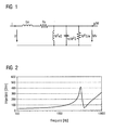
- eine Frequenzfunktion des Betrags der elektrischen Eingangsimpedanz eines typischen Hörgerätehörers.
- FIG. 1
- a simplified equivalent circuit diagram of an electromagnetic handset and
- FIG. 2
- a frequency function of the amount of electrical input impedance of a typical hearing aid earphone.
Die nachfolgend näher geschilderten Ausführungsbeispiele stellen bevorzugte Ausführungsformen der vorliegenden Erfindung dar.The embodiments described in more detail below represent preferred embodiments of the present invention represents.
Erfindungsgemäß wird die Tatsache genutzt, dass bei einem elektromagnetischen Wandler dessen mechanische Elemente und die daran gekoppelten schwingenden Massen die elektrische Impedanz, d. h. das Verhältnis der Spannung U zur Strom I, beeinflussen. Ein entsprechendes vereinfachtes Ersatzschaltbild des elektromagnetischen Hörers ist in FIG 1 dargestellt. Dementsprechend ergibt sich die elektrische Impedanz U/I des Hörers aus einer Serienschaltung der Spuleninduktivität Le und des Gleichstromwiderstands Re mit einer Parallelschaltung aus einer Induktivität M2nS, einer Kapazität m/M2S und eines Widerstands M2S/w. Dabei bedeuten M die elektromagnetische Wandlerkonstante, S die Membranfläche, n die Nachgiebigkeit der Membranaufhängung und des Lastvolumens, m die Membranmasse und w die Verluste. Alle Elemente sind hierzu auf elektrische Größen bezogen.According to the invention, the fact is used that in an electromagnetic transducer whose mechanical elements and the oscillating masses coupled thereto influence the electrical impedance, ie the ratio of the voltage U to the current I. A corresponding simplified equivalent circuit diagram of the electromagnetic receiver is shown in FIG. Accordingly, the electrical impedance U / I of the receiver results from a series connection of the coil inductance Le and the DC resistance Re with a parallel connection of an inductance M 2 nS, a capacitance m / M 2 S and a resistance M 2 S / w. Where M is the electromagnetic transducer constant, S is the membrane area, n is the compliance of the membrane suspension and the load volume, m is the membrane mass, and w are the losses. All elements are related to electrical quantities.
Die Ausgangsseite des in FIG 1 dargestellten Vierpols wird durch die Größen p/M entsprechend einem Strom und Mv entsprechend einer Spannung bestimmt. Dabei bedeuten p den Schalldruck und v die Schallschnelle.The output side of the quadrupole shown in FIG. 1 becomes by the quantities p / M corresponding to a current and Mv accordingly determined a voltage. Where p is the sound pressure and v the speed of sound.
Das Ersatzschaltbild macht unmittelbar deutlich, dass eine mechanische Resonanz des Systems sich unmittelbar in der elektrischen Impedanz wiederspiegelt. Dies erklärt auch den Kurvenverlauf des in FIG 2 dargestellten Betrags der elektrischen Eingangsimpedanz eines typischen Hörgerätehörers. Im niederfrequenten Bereich ist der Gleichstromwiderstand Re maßgeblich, wogegen im hochfrequenten Bereich induktives Verhalten primär verursacht durch die Spuleninduktivität Le mit einem Anstieg von ca. 6 dB/Oktave vorherrscht. Im mittelfrequenten Bereich machen sich die parallel geschalteten Komponenten von FIG 1, die das mechanische System repräsentieren, bemerkbar. Sie führen zu einem typischen Resonanzverlauf des Impedanzspektrums aufgrund der mechanischen Resonanz. Im Fall von FIG 2 liegt der Resonanz-Peak bei ca. 3200 Hz.The equivalent circuit diagram makes it immediately clear that a mechanical resonance of the system is directly in the reflecting electrical impedance. This also explains the Curve of the amount shown in FIG 2 of the electrical Input impedance of a typical hearing aid handset. in the Low frequency range is the DC resistance Re decisive, whereas in the high-frequency range inductive behavior primarily caused by the coil inductance Le with an increase of about 6 dB / octave prevails. In the medium-frequency Area make the parallel components of FIG. 1, which represent the mechanical system, noticeable. They lead to a typical resonance course of the Impedance spectrum due to the mechanical resonance. In the case of FIG 2, the resonance peak is about 3200 Hz.
Die Frequenz der mechanischen Resonanz wird im Wesentlichen durch die Masse der bewegten Hörerteile, z. B. Membran, der Membranaufhängung und dem Lastvolumen, insbesondere dem Gehörgangsvolumen, bestimmt. Ist der Frequenzverlauf der elektrischen Eingangsimpedanz des sich am Normkuppler befindlichen Hörers bekannt, so können individuelle Abweichungen von dem Normvolumen anhand einer Verschiebung der mechanischen Resonanzfrequenz abgeschätzt werden. Ist das Restvolumen des Gehörgangs kleiner als das Normvolumen, verschiebt sich die Resonanzfrequenz nach oben. Andernfalls verschiebt sie sich nach unten. Zur Korrektur des Normfrequenzgangs werden die Abweichungswerte der Anpasssoftware zugeführt. The frequency of mechanical resonance becomes essentially by the mass of the moving listener parts, z. B. membrane, the Membrane suspension and the load volume, in particular the auditory canal volume, certainly. Is the frequency response of the electrical Input impedance of the located on the standard coupler Earpiece known, so may individual deviations from the standard volume by means of a shift of the mechanical Resonant frequency can be estimated. Is the residual volume of Ear canal smaller than the standard volume, the shifts Resonance frequency upwards. Otherwise, it shifts downward. To correct the standard frequency response, the Deviation values supplied to the fitting software.
Der Hauptvorteil des erfindungsgemäßen Verfahrens besteht in der Einfachheit der Handhabung. Es ist nämlich kein zusätzliches Messgerät zur Bestimmung der akustischen Verhältnisse im Gehörgang notwendig. Der Schalldruck im Gehörgang kann vielmehr indirekt durch Bestimmung der elektrischen Eingangsimpedanz des Hörers mit Hilfe des Signalverarbeitungschips des Hörgeräts ermittelt werden. Dabei kann die elektrische Impedanzmessung im Normalbetrieb, d. h. in normaler Umgebung mit natürlichen Schallquellen, durchgeführt werden, wenn das Ausgangssignal des Signalverarbeitungschips genügend Energie in den interessierenden Frequenzbereichen hat. Ist dies allerdings nicht der Fall, wenn die natürliche Schallquelle beispielsweise zu leise oder zu stark verdeckt ist, so ist eine Anpassmessung mit künstlicher Beschallung des Hörgeräts notwendig.The main advantage of the method according to the invention consists in the simplicity of handling. It is not an additional one Measuring device for determining the acoustic conditions in the Auditory canal necessary. The sound pressure in the auditory canal can rather indirectly by determining the electrical input impedance of the listener with the help of the signal processing chip of the Hearing aid to be determined. In this case, the electrical impedance measurement in normal operation, d. H. in normal environment with natural sound sources, are performed when the output signal of signal processing chip enough energy in has the frequency ranges of interest. Is this, however not the case when the natural sound source, for example is too quiet or too covered, so is one Adaptation measurement with artificial sound of the hearing aid necessary.
Claims (4)
Applications Claiming Priority (2)
| Application Number | Priority Date | Filing Date | Title |
|---|---|---|---|
| DE10343291 | 2003-09-18 | ||
| DE10343291A DE10343291B3 (en) | 2003-09-18 | 2003-09-18 | Hearing aid and method for adjusting a hearing aid |
Publications (3)
| Publication Number | Publication Date |
|---|---|
| EP1517583A2 true EP1517583A2 (en) | 2005-03-23 |
| EP1517583A3 EP1517583A3 (en) | 2009-12-23 |
| EP1517583B1 EP1517583B1 (en) | 2013-12-04 |
Family
ID=34177822
Family Applications (1)
| Application Number | Title | Priority Date | Filing Date |
|---|---|---|---|
| EP04021501.4A Not-in-force EP1517583B1 (en) | 2003-09-18 | 2004-09-09 | Hearing aid for determination of the volume of the auditory canal and related adaptation method |
Country Status (4)
| Country | Link |
|---|---|
| US (1) | US7302069B2 (en) |
| EP (1) | EP1517583B1 (en) |
| DE (1) | DE10343291B3 (en) |
| DK (1) | DK1517583T3 (en) |
Cited By (1)
| Publication number | Priority date | Publication date | Assignee | Title |
|---|---|---|---|---|
| US8855323B2 (en) | 2007-07-10 | 2014-10-07 | Widex A/S | Method for identifying a receiver in a hearing aid |
Families Citing this family (14)
| Publication number | Priority date | Publication date | Assignee | Title |
|---|---|---|---|---|
| US20030163021A1 (en) * | 2002-02-26 | 2003-08-28 | Miller Douglas Alan | Method and system for external assessment of hearing aids that include implanted actuators |
| US7940945B2 (en) * | 2006-07-06 | 2011-05-10 | Phonak Ag | Method for operating a wireless audio signal receiver unit and system for providing hearing assistance to a user |
| EP2073570B1 (en) * | 2007-12-18 | 2013-08-21 | Oticon A/S | Adaptive hearing device and method for providing a hearing aid |
| EP2056624A1 (en) | 2008-04-10 | 2009-05-06 | Oticon A/S | Method of controlling a hearing device and hearing device |
| DE102010041337B4 (en) * | 2010-09-24 | 2013-07-18 | Siemens Medical Instruments Pte. Ltd. | Method for adjusting a hearing aid with in-situ audiometry and hearing aid |
| US9155887B2 (en) | 2010-10-19 | 2015-10-13 | Cochlear Limited | Relay interface for connecting an implanted medical device to an external electronics device |
| US20120281845A1 (en) * | 2011-05-05 | 2012-11-08 | Sony Ericsson Mobile Communications Ab | Method for determining an impedance of an electroacoustic transducer and for operating an audio playback device |
| WO2012165976A1 (en) * | 2011-06-01 | 2012-12-06 | Phitek Systems Limited | In-ear device incorporating active noise reduction |
| US9264811B1 (en) | 2014-04-16 | 2016-02-16 | Audyssey Laboratories | EQ correction for source device impedance and output device impedance interactions |
| WO2016057018A1 (en) * | 2014-10-06 | 2016-04-14 | Advanced Bionics Ag | Systems and methods for fitting an electro-acoustic stimulation system to a patient |
| EP3207720B1 (en) * | 2014-10-15 | 2019-01-09 | Widex A/S | Method of operating a hearing aid system and a hearing aid system |
| DK3207719T3 (en) * | 2014-10-15 | 2019-03-11 | Widex As | PROCEDURE TO OPERATE A HEARING SYSTEM AND HEARING SYSTEM |
| DK3062532T3 (en) * | 2015-02-27 | 2018-10-22 | Bernafon Ag | PROCEDURE FOR ADAPTING A HEARING DEVICE TO A USER'S EAR AND A HEARING DEVICE |
| US10348891B2 (en) | 2015-09-06 | 2019-07-09 | Deborah M. Manchester | System for real time, remote access to and adjustment of patient hearing aid with patient in normal life environment |
Citations (4)
| Publication number | Priority date | Publication date | Assignee | Title |
|---|---|---|---|---|
| WO2000028784A1 (en) | 1998-11-09 | 2000-05-18 | Tøpholm & Westermann APS | Method for in-situ measuring and in-situ correcting or adjusting a signal process in a hearing aid with a reference signal processor |
| US6269318B1 (en) | 1997-04-30 | 2001-07-31 | Earl R. Geddes | Method for determining transducer linear operational parameters |
| EP1181950A2 (en) | 2000-08-25 | 2002-02-27 | Cochlear Limited | Implantable hearing system having means for measuring the coupling quality |
| DE10104711A1 (en) | 2001-02-02 | 2002-04-25 | Siemens Audiologische Technik | Hearing aid operating method uses signal representing sound field in hearing tract of wearer for adaption of signal processing unit of hearing aid |
Family Cites Families (1)
| Publication number | Priority date | Publication date | Assignee | Title |
|---|---|---|---|---|
| DE4128172C2 (en) * | 1991-08-24 | 2000-07-13 | Ascom Audiosys Ag Flamatt | Digital hearing aid |
-
2003
- 2003-09-18 DE DE10343291A patent/DE10343291B3/en not_active Expired - Fee Related
-
2004
- 2004-09-09 DK DK04021501.4T patent/DK1517583T3/en active
- 2004-09-09 EP EP04021501.4A patent/EP1517583B1/en not_active Not-in-force
- 2004-09-17 US US10/944,589 patent/US7302069B2/en active Active
Patent Citations (5)
| Publication number | Priority date | Publication date | Assignee | Title |
|---|---|---|---|---|
| US6269318B1 (en) | 1997-04-30 | 2001-07-31 | Earl R. Geddes | Method for determining transducer linear operational parameters |
| WO2000028784A1 (en) | 1998-11-09 | 2000-05-18 | Tøpholm & Westermann APS | Method for in-situ measuring and in-situ correcting or adjusting a signal process in a hearing aid with a reference signal processor |
| EP1181950A2 (en) | 2000-08-25 | 2002-02-27 | Cochlear Limited | Implantable hearing system having means for measuring the coupling quality |
| DE10041726C1 (en) | 2000-08-25 | 2002-05-23 | Implex Ag Hearing Technology I | Implantable hearing system with means for measuring the coupling quality |
| DE10104711A1 (en) | 2001-02-02 | 2002-04-25 | Siemens Audiologische Technik | Hearing aid operating method uses signal representing sound field in hearing tract of wearer for adaption of signal processing unit of hearing aid |
Cited By (1)
| Publication number | Priority date | Publication date | Assignee | Title |
|---|---|---|---|---|
| US8855323B2 (en) | 2007-07-10 | 2014-10-07 | Widex A/S | Method for identifying a receiver in a hearing aid |
Also Published As
| Publication number | Publication date |
|---|---|
| DK1517583T3 (en) | 2014-03-10 |
| EP1517583A3 (en) | 2009-12-23 |
| US20050105741A1 (en) | 2005-05-19 |
| DE10343291B3 (en) | 2005-04-21 |
| US7302069B2 (en) | 2007-11-27 |
| EP1517583B1 (en) | 2013-12-04 |
Similar Documents
| Publication | Publication Date | Title |
|---|---|---|
| DE10041726C1 (en) | Implantable hearing system with means for measuring the coupling quality | |
| EP1517583B1 (en) | Hearing aid for determination of the volume of the auditory canal and related adaptation method | |
| DE19914993C1 (en) | Fully implantable hearing system with telemetric sensor testing has measurement and wireless telemetry units on implant side for transmitting processed signal to external display/evaluation unit | |
| EP1032109B1 (en) | Method and device to assist the positioning of an external transmitting part relating to an implantable receiving part of an implantable medical devices's charging system | |
| DE102005028742B3 (en) | Hearing aid equipment, has signal source delivering test signal that is not directly coming from input signal, where information signal is delivered by equipment such that information signal is delivered from source and used as test signal | |
| DE102010041337B4 (en) | Method for adjusting a hearing aid with in-situ audiometry and hearing aid | |
| EP1290914B1 (en) | Method for adjustment of a hearing aid to suit an individual | |
| EP2178313B1 (en) | Method and hearing aid for parameter adaption by determining a speech intelligibility threshold | |
| EP2180726A1 (en) | Sound localization in binaural hearing aids | |
| DE102005020317A1 (en) | Automatic gain adjustment on a hearing aid | |
| DE10131964A1 (en) | Method for operating a digital programmable hearing aid and digital programmable hearing aid | |
| EP1453358B1 (en) | Apparatus and method for adjusting a hearing aid | |
| EP1898670B1 (en) | Method and device for determining an effective vent | |
| EP1850634A2 (en) | Method for setting a hearing aid with high frequency amplification | |
| EP1728322A1 (en) | Circuit arrangement and signal processing device | |
| DE102012203349A1 (en) | Method for adapting a hearing device based on the sensory memory | |
| DE102016103297B4 (en) | Device and method for configuring a user-specific hearing system | |
| DE102006042085B4 (en) | A method for adapting a hearing aid using a morphometric feature of the hearing aid wearer, arrangement for carrying out the method and hearing aid system | |
| DE102013207080B4 (en) | Binaural microphone adaptation using your own voice | |
| DE10115430C1 (en) | Automatic calibration method for hearing aid adjustment system uses feedback of reproduced tone sequence detected by hearing aid microphone for correction of transmission errors | |
| EP1416764A2 (en) | Method of setting parameters of a hearing aid and device for carrying out this method | |
| DE102007053188A1 (en) | Consumer electronics device with headphones | |
| DE102011114560B4 (en) | Method for adapting a hearing aid | |
| DE102017216829B4 (en) | Method for adjusting an acoustic setting in a hearing aid | |
| CH719643A2 (en) | Method and system for verifying hearing aids with a frequency-changing function |
Legal Events
| Date | Code | Title | Description |
|---|---|---|---|
| PUAI | Public reference made under article 153(3) epc to a published international application that has entered the european phase |
Free format text: ORIGINAL CODE: 0009012 |
|
| AK | Designated contracting states |
Kind code of ref document: A2 Designated state(s): AT BE BG CH CY CZ DE DK EE ES FI FR GB GR HU IE IT LI LU MC NL PL PT RO SE SI SK TR |
|
| AX | Request for extension of the european patent |
Extension state: AL HR LT LV MK |
|
| PUAL | Search report despatched |
Free format text: ORIGINAL CODE: 0009013 |
|
| AK | Designated contracting states |
Kind code of ref document: A3 Designated state(s): AT BE BG CH CY CZ DE DK EE ES FI FR GB GR HU IE IT LI LU MC NL PL PT RO SE SI SK TR |
|
| AX | Request for extension of the european patent |
Extension state: AL HR LT LV MK |
|
| 17P | Request for examination filed |
Effective date: 20091207 |
|
| 17Q | First examination report despatched |
Effective date: 20091228 |
|
| AKX | Designation fees paid |
Designated state(s): CH DE DK FR GB LI |
|
| GRAP | Despatch of communication of intention to grant a patent |
Free format text: ORIGINAL CODE: EPIDOSNIGR1 |
|
| INTG | Intention to grant announced |
Effective date: 20130702 |
|
| GRAS | Grant fee paid |
Free format text: ORIGINAL CODE: EPIDOSNIGR3 |
|
| GRAA | (expected) grant |
Free format text: ORIGINAL CODE: 0009210 |
|
| AK | Designated contracting states |
Kind code of ref document: B1 Designated state(s): CH DE DK FR GB LI |
|
| REG | Reference to a national code |
Ref country code: GB Ref legal event code: FG4D Free format text: NOT ENGLISH |
|
| REG | Reference to a national code |
Ref country code: DE Ref legal event code: R081 Ref document number: 502004014450 Country of ref document: DE Owner name: SIVANTOS GMBH, DE Free format text: FORMER OWNER: SIEMENS AUDIOLOGISCHE TECHNIK GMBH, 91058 ERLANGEN, DE |
|
| REG | Reference to a national code |
Ref country code: CH Ref legal event code: NV Representative=s name: SIEMENS SCHWEIZ AG, CH Ref country code: CH Ref legal event code: EP |
|
| REG | Reference to a national code |
Ref country code: DE Ref legal event code: R096 Ref document number: 502004014450 Country of ref document: DE Effective date: 20140130 |
|
| REG | Reference to a national code |
Ref country code: DK Ref legal event code: T3 Effective date: 20140303 |
|
| REG | Reference to a national code |
Ref country code: DE Ref legal event code: R097 Ref document number: 502004014450 Country of ref document: DE |
|
| PLBE | No opposition filed within time limit |
Free format text: ORIGINAL CODE: 0009261 |
|
| STAA | Information on the status of an ep patent application or granted ep patent |
Free format text: STATUS: NO OPPOSITION FILED WITHIN TIME LIMIT |
|
| 26N | No opposition filed |
Effective date: 20140905 |
|
| REG | Reference to a national code |
Ref country code: DE Ref legal event code: R097 Ref document number: 502004014450 Country of ref document: DE Effective date: 20140905 |
|
| REG | Reference to a national code |
Ref country code: DE Ref legal event code: R082 Ref document number: 502004014450 Country of ref document: DE Representative=s name: FDST PATENTANWAELTE FREIER DOERR STAMMLER TSCH, DE |
|
| REG | Reference to a national code |
Ref country code: DE Ref legal event code: R082 Ref document number: 502004014450 Country of ref document: DE Representative=s name: FDST PATENTANWAELTE FREIER DOERR STAMMLER TSCH, DE Ref country code: DE Ref legal event code: R081 Ref document number: 502004014450 Country of ref document: DE Owner name: SIVANTOS GMBH, DE Free format text: FORMER OWNER: SIEMENS AUDIOLOGISCHE TECHNIK GMBH, 91058 ERLANGEN, DE |
|
| REG | Reference to a national code |
Ref country code: FR Ref legal event code: PLFP Year of fee payment: 13 |
|
| REG | Reference to a national code |
Ref country code: FR Ref legal event code: PLFP Year of fee payment: 14 |
|
| REG | Reference to a national code |
Ref country code: FR Ref legal event code: PLFP Year of fee payment: 15 |
|
| PGFP | Annual fee paid to national office [announced via postgrant information from national office to epo] |
Ref country code: DK Payment date: 20190920 Year of fee payment: 16 Ref country code: FR Payment date: 20190923 Year of fee payment: 16 |
|
| PGFP | Annual fee paid to national office [announced via postgrant information from national office to epo] |
Ref country code: GB Payment date: 20190924 Year of fee payment: 16 |
|
| PGFP | Annual fee paid to national office [announced via postgrant information from national office to epo] |
Ref country code: DE Payment date: 20190923 Year of fee payment: 16 Ref country code: CH Payment date: 20190924 Year of fee payment: 16 |
|
| REG | Reference to a national code |
Ref country code: DE Ref legal event code: R119 Ref document number: 502004014450 Country of ref document: DE |
|
| REG | Reference to a national code |
Ref country code: DK Ref legal event code: EBP Effective date: 20200930 |
|
| REG | Reference to a national code |
Ref country code: CH Ref legal event code: PL |
|
| GBPC | Gb: european patent ceased through non-payment of renewal fee |
Effective date: 20200909 |
|
| PG25 | Lapsed in a contracting state [announced via postgrant information from national office to epo] |
Ref country code: DE Free format text: LAPSE BECAUSE OF NON-PAYMENT OF DUE FEES Effective date: 20210401 Ref country code: FR Free format text: LAPSE BECAUSE OF NON-PAYMENT OF DUE FEES Effective date: 20200930 |
|
| PG25 | Lapsed in a contracting state [announced via postgrant information from national office to epo] |
Ref country code: CH Free format text: LAPSE BECAUSE OF NON-PAYMENT OF DUE FEES Effective date: 20200930 Ref country code: LI Free format text: LAPSE BECAUSE OF NON-PAYMENT OF DUE FEES Effective date: 20200930 Ref country code: GB Free format text: LAPSE BECAUSE OF NON-PAYMENT OF DUE FEES Effective date: 20200909 |
|
| PG25 | Lapsed in a contracting state [announced via postgrant information from national office to epo] |
Ref country code: DK Free format text: LAPSE BECAUSE OF NON-PAYMENT OF DUE FEES Effective date: 20200930 |