EP1517581A2 - A method for optimal microphone array design under uniform acoustic coupling constraints - Google Patents
A method for optimal microphone array design under uniform acoustic coupling constraints Download PDFInfo
- Publication number
- EP1517581A2 EP1517581A2 EP04104469A EP04104469A EP1517581A2 EP 1517581 A2 EP1517581 A2 EP 1517581A2 EP 04104469 A EP04104469 A EP 04104469A EP 04104469 A EP04104469 A EP 04104469A EP 1517581 A2 EP1517581 A2 EP 1517581A2
- Authority
- EP
- European Patent Office
- Prior art keywords
- beamformer
- constraint
- combined
- beamformers
- response
- Prior art date
- Legal status (The legal status is an assumption and is not a legal conclusion. Google has not performed a legal analysis and makes no representation as to the accuracy of the status listed.)
- Granted
Links
Images


Classifications
-
- H—ELECTRICITY
- H04—ELECTRIC COMMUNICATION TECHNIQUE
- H04M—TELEPHONIC COMMUNICATION
- H04M9/00—Arrangements for interconnection not involving centralised switching
- H04M9/08—Two-way loud-speaking telephone systems with means for conditioning the signal, e.g. for suppressing echoes for one or both directions of traffic
- H04M9/082—Two-way loud-speaking telephone systems with means for conditioning the signal, e.g. for suppressing echoes for one or both directions of traffic using echo cancellers
-
- H—ELECTRICITY
- H04—ELECTRIC COMMUNICATION TECHNIQUE
- H04R—LOUDSPEAKERS, MICROPHONES, GRAMOPHONE PICK-UPS OR LIKE ACOUSTIC ELECTROMECHANICAL TRANSDUCERS; DEAF-AID SETS; PUBLIC ADDRESS SYSTEMS
- H04R3/00—Circuits for transducers, loudspeakers or microphones
- H04R3/005—Circuits for transducers, loudspeakers or microphones for combining the signals of two or more microphones
-
- H—ELECTRICITY
- H04—ELECTRIC COMMUNICATION TECHNIQUE
- H04R—LOUDSPEAKERS, MICROPHONES, GRAMOPHONE PICK-UPS OR LIKE ACOUSTIC ELECTROMECHANICAL TRANSDUCERS; DEAF-AID SETS; PUBLIC ADDRESS SYSTEMS
- H04R2430/00—Signal processing covered by H04R, not provided for in its groups
- H04R2430/20—Processing of the output signals of the acoustic transducers of an array for obtaining a desired directivity characteristic
Definitions
- the present invention is directed to audio conferencing systems, and more particularly to a method of beamformer design that equalizes the amount of acoustic coupling among a finite number of beams covering a desired spatial span while preserving directivity characteristics.
- Spatial directivity in audio conferencing systems can be achieved either through directional microphones or through proper combination of several omnidirectional microphones (referred to as microphone array technology).
- Beamforming may be used in a microphone array to discriminate a source position in a "noisy” environment by “weighting” or modifying the gain of the signal from each microphone to create a beam in a desired “look” direction toward the source (i.e. talker).
- acoustic echo cancellation For full-duplex operation, acoustic echo cancellation must be performed to prevent reverberation, howling, etc. (see M. Branstein and D. Ward, "Microphone Arrays. Signal Processing Techniques and Applications”. Springer Verlag, 2001, and H. Buchner, W. Herbordt, W. Kellermann, "An Efficient Combination of Multi-Channel Acoustic Echo Cancellation With a Beamforming Microphone Array', Proc. Int. Workshop on Hands-Free Speech Communication (HSC), pp. 55-58, Kyoto, Japan, April, 2001).
- One approach is to perform acoustic echo cancellation on all the microphone signals in parallel, which is computationally intensive.
- a second approach is to perform acoustic echo cancellation on the spatially filtered signal at the output of the beamformer (i.e. the output signal of the particular microphone facing the "look direction" at any given point in time).
- the challenge that this second approach presents to acoustic echo cancellation is accommodating variations in the characteristics of the directional signal that vary with the spatial area that the system is pointing to.
- the acoustic echo-path as well as the room characteristics (background noise, etc) may change suddenly as the system changes its look direction, for instance when switching to a different talker.
- the acoustic echo cancellation algorithm re-converges to the new characteristics (for instance new echo path) each time the system changes its look direction.
- This method reduces negative effects on echo cancellation due to variations in the acoustic echo path and room characteristics when the beams are switching from one look direction to other.
- One method to reduce the variations in the acoustic characteristics for the different sectors is to design the beamformers such that all sectors have the same response to the direct path and main energy component of the acoustic coupling; that is, the loudspeaker signal. This can be achieved through proper beamformer design.
- Techniques are known for designing beamformers under desired response constraints whereby a linear constraint is imposed to provide the same value of the response to the loudspeaker signal for all beamformers (i.e. all combinations of beamformer weights applied to the microphone signals). For example, see Barry D. Van Veen and Kevin M. Buckley, "Beamforming: a versatile approach to spatial filtering", IEEE ASSP magazine, April 1988, and James G. Ryan. "Near-field beamforming using microphone arrays", PhD thesis, Carleton University, November 1999.
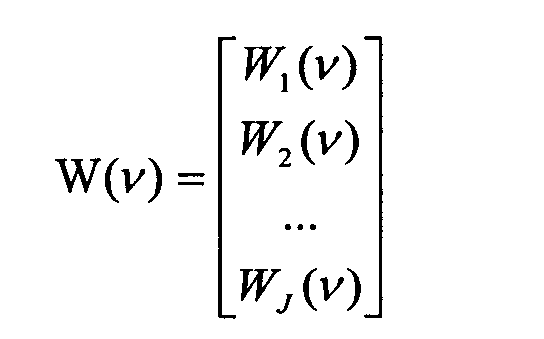
- the frequency-domain beamformer may be expressed as a complex weight vector W ( v ) of length M (where M is the number of microphones used).
- W ( v ) W H ( v ) S ( v ), where W H ( v ) denotes the Hermitian transpose (or complex conjugate transpose) of W ( v ).
- MVDR Minimum-Variance-Distortionless-Response
- a FIR filter can be designed to approximate the frequency response of the beamformer weights for each microphone, as explained in James G. Ryan. "Near-field beamforming using microphone arrays". PhD thesis, Carleton University, November 1999, referred to above.
- the above-described approach can be used to ensure a "null" response in a certain direction (for example a direction of interference). It can also be applied to the problem set forth above by equalizing the response of the beamformers to the loudspeaker signal. For that, one can constrain the response of each of J beamformers to be equal to a given arbitrary value "g", chosen a-priori.
- the main drawback of this design method is that the resulting beamformers are highly dependent on the arbitrary choice of the complex coupling response value (g).
- the choice of the magnitude and/or phase of this value may impose unnecessary stress on the solution of the optimization problem, resulting in a loss of directivity.
- an iterative procedure can be used to find, for each frequency, the coupling response value, g, such that optimal beamformers are obtained by (MVDR_2).
- MVDR_2 One example of criterion that can be used for the optimization problem is the cumulated Minimum Variance criterion:
- An object of the present invention is the provision of a method of designing a beamformer where no such arbitrary choice has to be made to achieve the uniform speakerphone response condition, and which results in optimal beamforming directivity (for the criterion above) under this uniform constraint.
- the key unique technical aspect of the present invention is in constraining the finite number of beamformers to have the same response to a loudspeaker signal (as well as the same gain in their respective look directions) without specifying the exact value of their response to this signal. This results in beamformer weights that are optimal in the Minimum Variance sense and satisfy the "uniform coupling" constraint.
- This technical aspect of the invention is achieved by re-defining the superdirective optimization problem as an optimization problem on the whole set of beamformers.
- the "minimum variance" condition combines all beamformer weights at once, and the uniform coupling constraint is expressed as a finite number of linear constraints on the weights of the individual beamformers, without specifying an arbitrary, a priori value for the actual value of the uniform response.
- the present invention relies on the recognition that for each sector, the response of the beamformer to the loudspeaker signal can be expressed in the frequency domain as a linear function of the beamformer weights. This allows the uniform coupling to be expressed as a finite number of linear constraints on the weights of a "combined beamformer", which ensures that the resulting constrained optimization problem has a unique, explicit solution.
- a combined beamformer for use in an audio conferencing system is provided according to claim 1.
- This aspect also provides an audio conferencing system comprising such a combined beamformer, together with a loudspeaker and a plurality of microphones.
- a method of making a combined beamformer is provided according to claim 2.
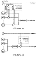
- Figure 1 shows one prior art approach to acoustic echo cancellation employing a bank of echo cancellers running in parallel on all of the microphone signals. As discussed above, this approach is computationally intensive.
- Figure 2 shows A second prior art approach is shown in Figure 2, whereby acoustic echo cancellation is performed on the spatially filtered signal at the output of the beamformer (i.e. the output signal of the particular microphone facing the "look direction" at any given point in time).
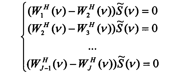
- the uniform coupling constraints may be expressed as ( J -1) linear constraints with the coefficients of the combined beamformer weights array, as follows:
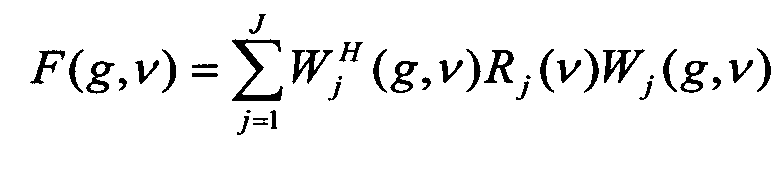
- the total variance estimator can also be combined as the summation of individual variance estimators:
- Figure 4 illustrates the loudspeaker coupling equalization obtained according to the method of the present invention for a microphone array having 6 microphones and 12 sectors.
- the thick line represents the equalized coupling response (that is the same for all 12 beams), whereas the thin lines represent the responses of the MVDR beamformers before coupling equalization.
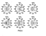
- Figure 5 shows, for this particular example, the effect of coupling equalization with the inventive method on the directivity of the beamformers. Only one of the 12 beamformers is shown, at different frequencies.
- Figure 5 illustrates the effect of an arbitrary choice of the equalization coupling response value using the prior art method based on (MVDR-2) with a target coupling value equal, for each frequency, to the magnitude of the coupling value provided by the equalization process obtained with the inventive method.
- the beampatterns in Figure 6 show that the directivity can be strongly affected, although it should be noted that the coupling response value only differs from the optimal one by its phase. If the target coupling response value also differs in magnitude, then further impact can be expected on the directivity.
- the method of the present invention can be applied to solve any problem similar to that discussed herein above where the uniform constraint, that is, the constraint that all the individual beamformers have to satisfy, can be expressed as a linear function of the beamformers' weights.
Landscapes
- Engineering & Computer Science (AREA)
- Signal Processing (AREA)
- Health & Medical Sciences (AREA)
- General Health & Medical Sciences (AREA)
- Otolaryngology (AREA)
- Physics & Mathematics (AREA)
- Acoustics & Sound (AREA)
- Circuit For Audible Band Transducer (AREA)
- Obtaining Desirable Characteristics In Audible-Bandwidth Transducers (AREA)
Abstract
Description
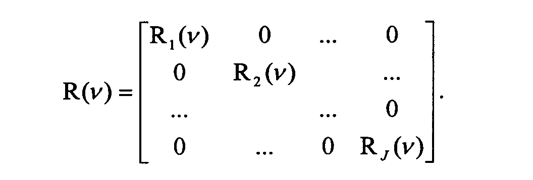
where R(v) is the noise correlation matrix (see [2] for details). This optimization problem has the following explicit solution:
and its solution is given by (MVDR_2):
Claims (3)
- A combined beamformer for use in an audio conferencing system having a loudspeaker and a plurality of M microphones for outputting respective signals, the combined beamformer comprising a plurality of J individual beamformers for modifying the gain of each of said signals by respective beamformer weight vectors Wj (v) of length M, where j = 1 to J, to create respective beams in respective look directions, said combined beamformer being characterized by a minimum variance condition that combines all of said beamformer weight vectors simultaneously assubject to the constraint WH (v)C(v) = G(v)
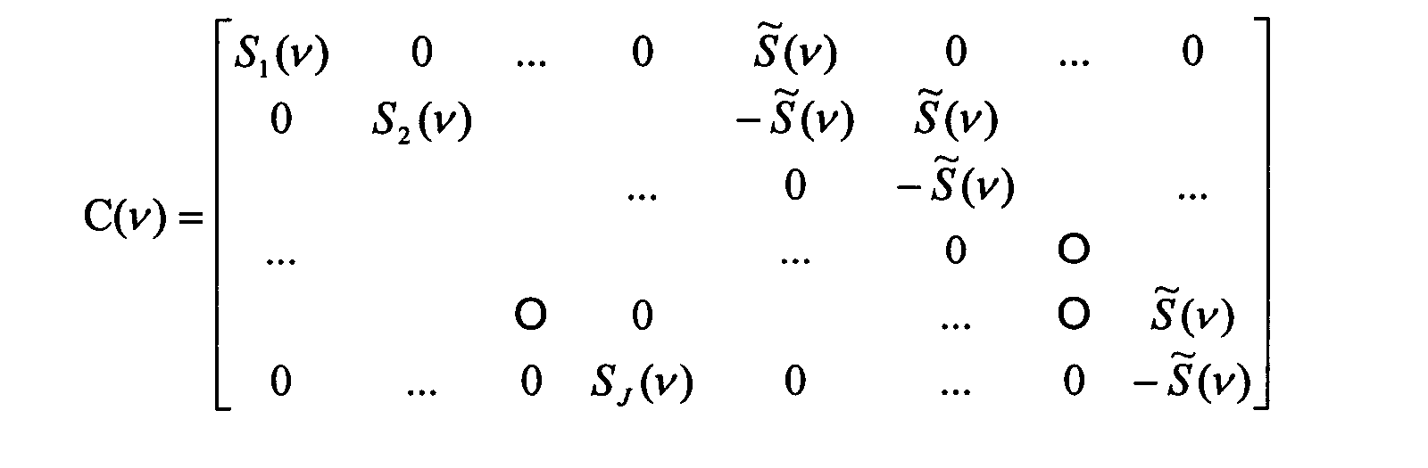
where W(v) is a vector of length M x J formed of concatenated vectors Wj (v), WH (v) denotes the Hermitian transpose of W(v), R(v) is a combined noise correlation matrix of size M x J by M x J, C(v) is a uniform coupling constraint matrix expressed as a finite number of linear constraints on the components of the concatenated weight vector W(v) and G(v) is a constraint response vector, a unique solution to said minimum variance condition being given by - An audio conferencing system comprising:a loudspeaker;a plurality of M microphones for outputting respective signals; anda combined beamformer according to claim 1.
- A method of making a combined beamformer for use in an audio conferencing system having a loudspeaker and a plurality of M microphones for outputting respective signals, said method comprising providing a plurality of J individual beamformers for modifying the gain of each of said signals by respective beamformer weight vectors Wj (v) of length M, where j = 1 to J, to create respective beams in respective look directions, subjecting said combined beamformer to a minimum variance condition that combines all of said beamformer weight vectors simultaneously assubject to the constraint WH (v)C(v) = G(v)

where W(v) is a vector of length M x J formed of concatenated vectors Wj (v), WH (v) denotes the Hermitian transpose of W(v) , R(v) is a combined noise correlation matrix of size M x J by M x J, C(v) is a uniform coupling constraint matrix expressed as a finite number of linear constraints on the components of the concatenated weight vector W(v) and G(v) is a constraint response vector, and providing a unique solution to said minimum variance condition, said solution being W(v) = R-1(v)C(v)[C H (v)R-1(v)C(v)-1 GH(v) such that individual ones of said beamformers satisfy said uniform coupling constraint and are optimal in terms of said minimum variance condition.
Applications Claiming Priority (2)
| Application Number | Priority Date | Filing Date | Title |
|---|---|---|---|
| GB3217221 | 2003-09-16 | ||
| GBGB0321722.1A GB0321722D0 (en) | 2003-09-16 | 2003-09-16 | A method for optimal microphone array design under uniform acoustic coupling constraints |
Publications (3)
| Publication Number | Publication Date |
|---|---|
| EP1517581A2 true EP1517581A2 (en) | 2005-03-23 |
| EP1517581A3 EP1517581A3 (en) | 2009-05-06 |
| EP1517581B1 EP1517581B1 (en) | 2011-11-16 |
Family
ID=29227212
Family Applications (1)
| Application Number | Title | Priority Date | Filing Date |
|---|---|---|---|
| EP04104469A Expired - Lifetime EP1517581B1 (en) | 2003-09-16 | 2004-09-15 | A method for optimal microphone array design under uniform acoustic coupling constraints |
Country Status (4)
| Country | Link |
|---|---|
| US (1) | US7630502B2 (en) |
| EP (1) | EP1517581B1 (en) |
| CA (1) | CA2481640C (en) |
| GB (1) | GB0321722D0 (en) |
Cited By (5)
| Publication number | Priority date | Publication date | Assignee | Title |
|---|---|---|---|---|
| EP1919251A1 (en) * | 2006-10-30 | 2008-05-07 | Mitel Networks Corporation | Beamforming weights conditioning for efficient implementations of broadband beamformers |
| WO2008133504A1 (en) * | 2007-04-27 | 2008-11-06 | Technische Universiteit Delft | Highly directive endfire loudspeaker array |
| GB2512705A (en) * | 2013-03-15 | 2014-10-08 | Csr Technology Inc | Method, apparatus, and manufacture for beamforming with fixed weights and adaptive selection or resynthesis |
| CN105578375A (en) * | 2015-12-31 | 2016-05-11 | 歌尔科技有限公司 | Microphone test device and test method |
| EP3614696A4 (en) * | 2017-04-20 | 2020-12-09 | Starkey Laboratories, Inc. | BEAM SHAPER, BEAM SHAPING PROCESS AND HEARING AID SYSTEM |
Families Citing this family (22)
| Publication number | Priority date | Publication date | Assignee | Title |
|---|---|---|---|---|
| EP1524879B1 (en) * | 2003-06-30 | 2014-05-07 | Nuance Communications, Inc. | Handsfree system for use in a vehicle |
| EP1581026B1 (en) * | 2004-03-17 | 2015-11-11 | Nuance Communications, Inc. | Method for detecting and reducing noise from a microphone array |
| US8457614B2 (en) | 2005-04-07 | 2013-06-04 | Clearone Communications, Inc. | Wireless multi-unit conference phone |
| US8175871B2 (en) * | 2007-09-28 | 2012-05-08 | Qualcomm Incorporated | Apparatus and method of noise and echo reduction in multiple microphone audio systems |
| US8954324B2 (en) * | 2007-09-28 | 2015-02-10 | Qualcomm Incorporated | Multiple microphone voice activity detector |
| US9392360B2 (en) | 2007-12-11 | 2016-07-12 | Andrea Electronics Corporation | Steerable sensor array system with video input |
| WO2009076523A1 (en) | 2007-12-11 | 2009-06-18 | Andrea Electronics Corporation | Adaptive filtering in a sensor array system |
| US8150054B2 (en) * | 2007-12-11 | 2012-04-03 | Andrea Electronics Corporation | Adaptive filter in a sensor array system |
| US8223988B2 (en) * | 2008-01-29 | 2012-07-17 | Qualcomm Incorporated | Enhanced blind source separation algorithm for highly correlated mixtures |
| CN102860039B (en) * | 2009-11-12 | 2016-10-19 | 罗伯特·亨利·弗莱特 | Hands-free phone and/or microphone array and method and system for using them |
| US8219394B2 (en) * | 2010-01-20 | 2012-07-10 | Microsoft Corporation | Adaptive ambient sound suppression and speech tracking |
| GB2493327B (en) | 2011-07-05 | 2018-06-06 | Skype | Processing audio signals |
| GB2495129B (en) | 2011-09-30 | 2017-07-19 | Skype | Processing signals |
| GB2495131A (en) | 2011-09-30 | 2013-04-03 | Skype | A mobile device includes a received-signal beamformer that adapts to motion of the mobile device |
| GB2495278A (en) | 2011-09-30 | 2013-04-10 | Skype | Processing received signals from a range of receiving angles to reduce interference |
| GB2495128B (en) | 2011-09-30 | 2018-04-04 | Skype | Processing signals |
| GB2495472B (en) | 2011-09-30 | 2019-07-03 | Skype | Processing audio signals |
| GB2496660B (en) | 2011-11-18 | 2014-06-04 | Skype | Processing audio signals |
| GB201120392D0 (en) | 2011-11-25 | 2012-01-11 | Skype Ltd | Processing signals |
| GB2497343B (en) | 2011-12-08 | 2014-11-26 | Skype | Processing audio signals |
| EP2884491A1 (en) * | 2013-12-11 | 2015-06-17 | Fraunhofer-Gesellschaft zur Förderung der angewandten Forschung e.V. | Extraction of reverberant sound using microphone arrays |
| CN112292870A (en) | 2018-08-14 | 2021-01-29 | 阿里巴巴集团控股有限公司 | Audio signal processing apparatus and method |
Family Cites Families (5)
| Publication number | Priority date | Publication date | Assignee | Title |
|---|---|---|---|---|
| US5532700A (en) * | 1995-03-16 | 1996-07-02 | The United States Of America As Represented By The Secretary Of The Navy | Preprocessor and adaptive beamformer for active signals of arbitrary waveform |
| CA2407855C (en) * | 2000-05-10 | 2010-02-02 | The Board Of Trustees Of The University Of Illinois | Interference suppression techniques |
| FR2828327B1 (en) * | 2000-10-03 | 2003-12-12 | France Telecom | ECHO REDUCTION METHOD AND DEVICE |
| CA2420989C (en) * | 2002-03-08 | 2006-12-05 | Gennum Corporation | Low-noise directional microphone system |
| CA2413217C (en) | 2002-11-29 | 2007-01-16 | Mitel Knowledge Corporation | Method of acoustic echo cancellation in full-duplex hands free audio conferencing with spatial directivity |
-
2003
- 2003-09-16 GB GBGB0321722.1A patent/GB0321722D0/en not_active Ceased
-
2004
- 2004-09-15 CA CA002481640A patent/CA2481640C/en not_active Expired - Lifetime
- 2004-09-15 EP EP04104469A patent/EP1517581B1/en not_active Expired - Lifetime
- 2004-09-16 US US10/941,961 patent/US7630502B2/en active Active
Cited By (7)
| Publication number | Priority date | Publication date | Assignee | Title |
|---|---|---|---|---|
| EP1919251A1 (en) * | 2006-10-30 | 2008-05-07 | Mitel Networks Corporation | Beamforming weights conditioning for efficient implementations of broadband beamformers |
| WO2008133504A1 (en) * | 2007-04-27 | 2008-11-06 | Technische Universiteit Delft | Highly directive endfire loudspeaker array |
| GB2512705A (en) * | 2013-03-15 | 2014-10-08 | Csr Technology Inc | Method, apparatus, and manufacture for beamforming with fixed weights and adaptive selection or resynthesis |
| GB2512705B (en) * | 2013-03-15 | 2020-01-08 | Csr Tech Inc | Method, apparatus, and manufacture for beamforming with fixed weights and adaptive selection or resynthesis |
| CN105578375A (en) * | 2015-12-31 | 2016-05-11 | 歌尔科技有限公司 | Microphone test device and test method |
| CN105578375B (en) * | 2015-12-31 | 2019-11-08 | 歌尔科技有限公司 | A kind of microphone test device and test method |
| EP3614696A4 (en) * | 2017-04-20 | 2020-12-09 | Starkey Laboratories, Inc. | BEAM SHAPER, BEAM SHAPING PROCESS AND HEARING AID SYSTEM |
Also Published As
| Publication number | Publication date |
|---|---|
| EP1517581B1 (en) | 2011-11-16 |
| CA2481640A1 (en) | 2005-03-16 |
| EP1517581A3 (en) | 2009-05-06 |
| CA2481640C (en) | 2007-02-06 |
| US20050232441A1 (en) | 2005-10-20 |
| GB0321722D0 (en) | 2003-10-15 |
| US7630502B2 (en) | 2009-12-08 |
Similar Documents
| Publication | Publication Date | Title |
|---|---|---|
| US7630502B2 (en) | Method for optimal microphone array design under uniform acoustic coupling constraints | |
| US11831812B2 (en) | Conferencing device with beamforming and echo cancellation | |
| US8184801B1 (en) | Acoustic echo cancellation for time-varying microphone array beamsteering systems | |
| Simmer et al. | Post-filtering techniques | |
| US7724891B2 (en) | Method to reduce acoustic coupling in audio conferencing systems | |
| EP2936830B1 (en) | Filter and method for informed spatial filtering using multiple instantaneous direction-of-arrivial estimates | |
| EP1278395B1 (en) | Second-order adaptive differential microphone array | |
| EP1184676A1 (en) | System and method for processing a signal being emitted from a target signal source into a noisy environment | |
| Adel et al. | Beamforming techniques for multichannel audio signal separation | |
| Kajala et al. | Filter-and-sum beamformer with adjustable filter characteristics | |
| EP3245795A2 (en) | Reverberation suppression using multiple beamformers | |
| Herbordtt et al. | Joint optimization of LCMV beamforming and acoustic echo cancellation for automatic speech recognition | |
| CA2506439C (en) | A parallel gsc structure for adaptive beamforming under equalization constraints | |
| Kumatani et al. | Microphone array post-filter based on spatially-correlated noise measurements for distant speech recognition | |
| Ito et al. | Designing the Wiener post-filter for diffuse noise suppression using imaginary parts of inter-channel cross-spectra | |
| Doclo et al. | SVD-based optimal filtering with applications to noise reduction in speech signals | |
| Kammeyer et al. | New aspects of combining echo cancellers with beamformers | |
| Spriet et al. | A unification of adaptive multi-microphone noise reduction systems | |
| Chen et al. | A new approach for speaker tracking in reverberant environment | |
| Dietzen et al. | On the relation between data-dependent beamforming and multichannel linear prediction for dereverberation | |
| Beaucoup | Parallel beamformer design under response equalization constraints | |
| Khayeri et al. | A hybrid near-field superdirective GSC and post-filter for speech enhancement | |
| Masgrau et al. | Performance comparison of several adaptive schemes for microphone array beamforming. | |
| Phan | Alternative approaches to generalized sidelobe canceler | |
| Avokh et al. | Speech enhancement using linearly constrained adaptive constant directivity beam-formers |
Legal Events
| Date | Code | Title | Description |
|---|---|---|---|
| PUAI | Public reference made under article 153(3) epc to a published international application that has entered the european phase |
Free format text: ORIGINAL CODE: 0009012 |
|
| AK | Designated contracting states |
Kind code of ref document: A2 Designated state(s): AT BE BG CH CY CZ DE DK EE ES FI FR GB GR HU IE IT LI LU MC NL PL PT RO SE SI SK TR |
|
| AX | Request for extension of the european patent |
Extension state: AL HR LT LV MK |
|
| RIN1 | Information on inventor provided before grant (corrected) |
Inventor name: BEAUCOUP, FRANCK Inventor name: TETELBAUM, MICHAEL |
|
| PUAL | Search report despatched |
Free format text: ORIGINAL CODE: 0009013 |
|
| AK | Designated contracting states |
Kind code of ref document: A3 Designated state(s): AT BE BG CH CY CZ DE DK EE ES FI FR GB GR HU IE IT LI LU MC NL PL PT RO SE SI SK TR |
|
| AX | Request for extension of the european patent |
Extension state: AL HR LT LV MK |
|
| 17P | Request for examination filed |
Effective date: 20090923 |
|
| AKX | Designation fees paid |
Designated state(s): DE FR GB |
|
| GRAP | Despatch of communication of intention to grant a patent |
Free format text: ORIGINAL CODE: EPIDOSNIGR1 |
|
| GRAS | Grant fee paid |
Free format text: ORIGINAL CODE: EPIDOSNIGR3 |
|
| GRAA | (expected) grant |
Free format text: ORIGINAL CODE: 0009210 |
|
| AK | Designated contracting states |
Kind code of ref document: B1 Designated state(s): DE FR GB |
|
| REG | Reference to a national code |
Ref country code: GB Ref legal event code: FG4D |
|
| REG | Reference to a national code |
Ref country code: DE Ref legal event code: R096 Ref document number: 602004035298 Country of ref document: DE Effective date: 20120126 |
|
| PLBE | No opposition filed within time limit |
Free format text: ORIGINAL CODE: 0009261 |
|
| STAA | Information on the status of an ep patent application or granted ep patent |
Free format text: STATUS: NO OPPOSITION FILED WITHIN TIME LIMIT |
|
| 26N | No opposition filed |
Effective date: 20120817 |
|
| REG | Reference to a national code |
Ref country code: DE Ref legal event code: R097 Ref document number: 602004035298 Country of ref document: DE Effective date: 20120817 |
|
| REG | Reference to a national code |
Ref country code: FR Ref legal event code: PLFP Year of fee payment: 13 |
|
| REG | Reference to a national code |
Ref country code: FR Ref legal event code: PLFP Year of fee payment: 14 |
|
| REG | Reference to a national code |
Ref country code: FR Ref legal event code: PLFP Year of fee payment: 15 |
|
| PGFP | Annual fee paid to national office [announced via postgrant information from national office to epo] |
Ref country code: GB Payment date: 20230727 Year of fee payment: 20 |
|
| PGFP | Annual fee paid to national office [announced via postgrant information from national office to epo] |
Ref country code: FR Payment date: 20230710 Year of fee payment: 20 Ref country code: DE Payment date: 20230718 Year of fee payment: 20 |
|
| REG | Reference to a national code |
Ref country code: DE Ref legal event code: R071 Ref document number: 602004035298 Country of ref document: DE |
|
| REG | Reference to a national code |
Ref country code: GB Ref legal event code: PE20 Expiry date: 20240914 |
|
| PG25 | Lapsed in a contracting state [announced via postgrant information from national office to epo] |
Ref country code: GB Free format text: LAPSE BECAUSE OF EXPIRATION OF PROTECTION Effective date: 20240914 |
|
| PG25 | Lapsed in a contracting state [announced via postgrant information from national office to epo] |
Ref country code: GB Free format text: LAPSE BECAUSE OF EXPIRATION OF PROTECTION Effective date: 20240914 |