EP1517578A2 - Radio frequency automatic meter reading system - Google Patents
Radio frequency automatic meter reading system Download PDFInfo
- Publication number
- EP1517578A2 EP1517578A2 EP04021011A EP04021011A EP1517578A2 EP 1517578 A2 EP1517578 A2 EP 1517578A2 EP 04021011 A EP04021011 A EP 04021011A EP 04021011 A EP04021011 A EP 04021011A EP 1517578 A2 EP1517578 A2 EP 1517578A2
- Authority
- EP
- European Patent Office
- Prior art keywords
- edge
- data rate
- inbound
- edges
- communication
- Prior art date
- Legal status (The legal status is an assumption and is not a legal conclusion. Google has not performed a legal analysis and makes no representation as to the accuracy of the status listed.)
- Granted
Links
Images







Classifications
-
- G—PHYSICS
- G08—SIGNALLING
- G08C—TRANSMISSION SYSTEMS FOR MEASURED VALUES, CONTROL OR SIMILAR SIGNALS
- G08C17/00—Arrangements for transmitting signals characterised by the use of a wireless electrical link
- G08C17/02—Arrangements for transmitting signals characterised by the use of a wireless electrical link using a radio link
-
- H—ELECTRICITY
- H04—ELECTRIC COMMUNICATION TECHNIQUE
- H04Q—SELECTING
- H04Q9/00—Arrangements in telecontrol or telemetry systems for selectively calling a substation from a main station, in which substation desired apparatus is selected for applying a control signal thereto or for obtaining measured values therefrom
Definitions
- the invention relates generally to radio frequency (RF) communication systems, and more particularly to RF communication schemes used with remote automatic meter reading (AMR) devices and systems.
- RF radio frequency
- AMR Automatic meter reading
- Utility companies for example, use AMR systems to read and monitor customer meters remotely, typically using radio frequency (RF) communications.
- RF radio frequency
- AMR systems are favored by utility companies and other users because the systems increase the efficiency and accuracy of collecting readings and managing customer billing. For example, using an AMR system for the monthly reading of residential gas, electric, or water meters eliminates the need for a utility employee to physically enter each residence or business where a meter is located to transcribe a meter reading by hand.
- endpoint devices at meter locations communicate with readers that collect readings and data using RF.
- endpoint device will be used to generally refer to the meter and meter interface unit that communicates with the reader as a single device, although in various embodiments the meter and meter interface unit may be distinct devices in electrical communication but not physical proximity with each other.
- a handheld or otherwise mobile reader with RF communication capabilities is used to collect data from endpoint devices as it is moved from place to place.
- U.S. Patent No. 5,914,673 relates to an AMR system of the type used for reading utility meters by using a fixed RF network.
- the system is a network comprised of multiple cells, with each cell containing a single data concentrator unit and a typically large number of meter interface units.
- each meter interface unit is assigned a unique time displacement number and responds to a meter reading request from a data concentrator unit based upon its time displacement number.
- Each endpoint device is typically equipped with a battery-powered meter interface unit that communicates with the reader.
- a battery-powered meter interface unit that communicates with the reader.
- the preferred method with which to increase battery life is to reduce battery consumption by the meter interface. This goal may be accomplished in part by operating the meter interface in a "sleep" or reduced power mode when communication with the reader is not expected or required.
- U.S. Patent No. 5,726,646 is directed to a method and apparatus for activating and accessing remote meter interface devices.
- a meter reading device initiates communication with a meter interface unit by transmitting a request on a communication channel.
- the meter interface unit is operable between an active and inactive state to reduce power consumption and is periodically activated to monitor a communication channel for channel activity.
- the request from the meter reading device includes a unit identifier, and the meter interface unit is activated at a particular time period and detects communication activity on the communication channel originating from the meter reading device.
- U.S. Patent No. 5,684,472 is directed to a method and apparatus for remotely accessing meter status information in a meter reading system. Communications between battery powered meter interface units and a meter reading device occur at a first data rate, while communications between the externally powered meter interface units and the meter reading device occur at a second data rate different than the first data rate. Communications between battery powered meter interface units and externally powered meter interface units occur at different rates so that more frequent communication with externally powered meter interface units does not result in extended receiver on-time for the battery powered meter interface units.
- the invention disclosed and described herein substantially meets the aforementioned needs of the industry by providing a system and method for fast detection of specific on-air data rates.
- the system and method enable an endpoint device to quickly determine the existence of over-the-air information that is specifically targeted to a unique class of AMR devices.
- the digital squelch system and the method of implementation conserve battery life in the endpoint device and are an improvement over prior art analog squelch systems and methods that only look for the presence of an RF signal over a specific threshold.
- an endpoint device utilizing the digital squelch circuitry and algorithm of the invention can quickly and precisely determine if the AMR system is communicating with its class of AMR device by looking for a specific non-standard data rate present on the air.
- This method therefore allows for a significant improvement in battery life in two-way units.
- the digital squelch technique can be extended to multiple similar data rates in the same geographic area to further extend endpoint device battery life. This is accomplished because the digital squelch method is sensitive over a very narrow range, allowing for multiple unique classes of endpoint devices with very similar RF and data transfer performance. Further, the digital squelch method enables even faster determination of inappropriate data rates and of no signal present situations, in which case only noise would be detected.
- embodiments of the digital squelch system and method enable an endpoint device to evaluate the data rate of an inbound signal and quickly determine if the signal has the correct data rate for a specific class of endpoint devices. This is an improvement over the prior art because it does not require bit or frame synchronization to operate properly, making it much faster than the methods previously described.
- the method also does not depend on the level of RF being received. This enables the system to operate well at low signal levels, avoiding false triggering at high interfering signal levels and making it well suited to ISM bands or in licensed channels where strong adjacent channel interference may be encountered.
- AMR systems typically comprise a plurality of endpoint devices, for example utility consumption meters, geographically distributed in a local area.
- AMR systems are typically most useful in residential and business environments in which meter densities are relatively high and in which it would be costly and time-consuming for a utility employee to physically visit each meter.
- a relatively larger geographic area for example a city, could include more than one AMR system operating in close geographic and communicative proximity.
- each endpoint device is in electrical communication with a fixed or mobile reader or an intermediate endpoint device to routinely collect meter readings and exchange data and other information.
- each endpoint device In areas in which more than one AMR system are operating, or in applications in which the reader is requesting communication with specific devices, each endpoint device must determine whether over-the-air communications are directed to it or to its class in order to properly respond to the communication.
- the digital squelch method of the invention described herein enables AMR system endpoint devices to quickly and efficiently analyze over-the-air communications to identify those communications that are targeting a particular device or class of devices.
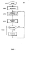
- FIG. 1 is a flow chart of one example embodiment of a digital squelch identification technique 100 of the invention.
- Digital squelch technique 100 is implemented by each of a plurality of microprocessor circuitry equipped endpoint devices operating within a fixed network AMR system utilizing RF communications for data gathering and transfer. More particularly, the digital squelch identification technique provides for fast detection of a specific Manchester on-air data rate that enables an endpoint device to quickly determine the existence of over-the-air information that is specifically targeted to its unique class of AMR devices.
- Capture/compare interrupt 104 is the step that follows in which the digital squelch identification or filtering process takes place and is described in further detail below. If a valid signal is detected by the endpoint device in step 104, the digital squelch filtering process is terminated and the decoding process is initiated in order to act upon the detected signal. A valid signal is one targeting a particular endpoint device or device class.
- a valid signal is not detected in step 104, the digital squelch filtering process ends and control is passed back to the calling function with a ''NO SIGNAL" indication.
- a "NO SIGNAL" condition is determined very quickly, on the order of ten expected bit widths or less, and the endpoint device powers down quickly in order to conserve battery life.
- capture/compare interrupt step 104 collects edges and sorts the timestamps in order to determine whether the inbound signal comprises a particular non-standard data rate. If the appropriate non-standard data rate is detected, the inbound signal is directed to that particular endpoint device and further communications, for example an outbound signal including a consumption reading, are initiated as determined by the inbound signal contents.
- capture/compare interrupt 104 is turned off and a Timer A of interrupt step 106 is turned on. Timer A of interrupt 106 is used to mark a Manchester bit frame.
- the value for the start of the Manchester bit frame is loaded into a register at the end of a successful digital squelch process. This value is used to time the start and end of the Manchester bit frame, where phase was determined in the squelch process.
- Fig. 1 also illustrates a re-sampling loop 108 for sampling of the incoming signal data rate until no more samples are needed or requested.
- FIG. 2 is a timing diagram 200 of one embodiment of the digital squelch method and system of the invention, wherein the system is configured at capture/compare interrupt step 104 to collect edges and sort the timestamps as follows.
- all communications from the central radio to the endpoint devices in the system are Manchester-encoded.
- Manchester encoding is a synchronous clock encoding technique used to encode the clock and data of a synchronous bit stream.
- a Manchester bit frame is defined as the period of time from the start to the end of one Manchester data bit.
- a transition must occur in the center of the Manchester bit frame.
- a full bit is the time from the start to the end of one Manchester data bit. In one example embodiment of the digital squelch method of the invention, there should be a transition at the full bit point.
- a base edge is the timestamp value of the edge from which the next edge is measured, and a zero edge is the first base edge.
- Bad edges are the total edges that do not fall into a half bit or a full bit category from the start of a detection cycle.
- Good edges are the total edges that fall into the half bit or full bit category from the start of a detection cycle.
- a good phase count is thus the total number of good edges that qualify as edges that can be used to determine phase; for example, two edges received that are one full bit apart and have no edges between them are two good phase edges.
- NRZ non-return to zero
- straight binary encoding is used.
- an edge at the start of timeframe A 112 is a base edge in the embodiment of FIG. 2.
- An edge detected during timeframe A 112 occurs too soon to be a good edge. If such an edge is detected, the bad edge count register is incremented and the good phase count register is cleared.
- a good half bit occurs at timeframe B 114. The good count is incremented and the edge at B 114 becomes the base edge plus or minus half of the error. If the previous good edge was not a possible clock edge, then the current edge becomes a possible clock edge.
- An edge detected during timeframe C 116 occurs too late for a half bit and too early for a full bit. At C 116, therefore, the bad count is incremented and the good phase count is cleared.
- a good full bit occurs at time frame D 118.
- the good count and the good phase count are incremented and, because this is a clock edge, the edge in D 118 becomes the base edge plus or minus half of the error.
- An edge occurring during timeframe E 120 occurs too late to be a full bit.
- the bad count is incremented and this edge is the base edge, or zero edge.
- the phase count is also cleared.
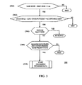
- FIG. 3 is a flowchart of one example embodiment of this selectivity test 300.
- the timing between the base edge and the zero edge is analyzed at step 302. If the value resulting from step 302 is within an acceptable limit at step 304, the bad edges are then reviewed at step 306. If enough bad edges have been detected in step 306, no valid incoming signal is present. Otherwise, the good edge count is then analyzed at step 308.
- test 300 If test 300 is performed successfully, the inbound signal is considered valid and the receiving endpoint device begins processing the incoming signal data at step 310.
- capture/compare interrupt operation at step 104 is turned off and the Timer A of interrupt step 106 is turned on.
- Timer A of interrupt 106 is used to mark the Manchester bit frame.
- the value for the start of the Manchester bit frame is loaded into a register at the end of a successful digital squelch process. This value is used to time the start and end of the Manchester bit frame, where phase was determined in the squelch process.
- the endpoint device is able to quickly determine whether over-the-air information is being targeted to its unique class of AMR device through the specific on-air data rate of the signal detected as described above.
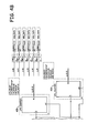
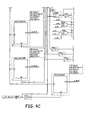
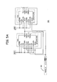
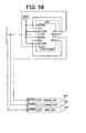
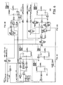
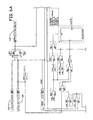
- FIGS. 4-6 are hardware schematics configured in accordance with one example embodiment of the invention.
- FIG. 4 is a hardware schematic of a dual windower (or edge detector);
- FIG. 5 is a hardware schematic of a divider circuit while
- FIG. 6 is a hardware schematic of a decoder in accordance with one example embodiment of the invention.
- raw data signal 402 is clocked into a shift register 404 at a rate much higher than the data rate.
- Signal 402 is a quantized or clock-synchronized version of data coming out of a data slicer (refer to FIG. 6), or a receiver returning a digital data stream.
- Shift register 404 is used to delay signal 402.
- the delayed data is then presented to a 2-bit EXCLUSIVE-OR gate 406, which finds data transitions, or edges. Windows are formed by counters 408 and 410 to evaluate the data transitions to determine, similarly to the software approach described above, if the data transitions fall into "good” windows or "bad” windows.
- Edge detector circuit 400 also receives its clock signal 412 from circuit 500 (see FIG. 5).
- a good edge is detected and then the next several edges detected are analyzed to determine whether the edges fall within "good" windows of where the edge would be expected to be if the detected signal is at the data rate being sought.
- One of the goals is to accumulate a set number of good transitions, or transitions that would indicate a preferred data rate, before accumulating a set number of bad transitions that are transitions occurring outside of the windows accumulating good counts. If a subsequent edge falls within a window, counter 408, the "good count,” is incremented. If an edge falls outside the window, it is a "bad count” and counter 410 is incremented.
- circuit 400 indicates that a valid data rate is present. If counter 410 reaches its value before counter 408, circuit 400 indicates that an invalid data rate, i.e. a data rate that is not the preferred or target data rate, is present, which indicates to the system that it is unnecessary to continue acquisition. The system will also cease detecting and analyzing edges if a predetermined acquisition timeout is reached in which no valid data rate has been detected.
- window widths or sizes are adjustable and customizable so as to allow for taking into account bit jitter and other anomalies, allowing optimization of the sensitivity and false rate.
- the good count and bad count values are also adjustable so as to optimize tradeoffs between speed, sensitivity, power consumption, and false rate, among other parameters.
- the data rate and other related parameters are also customizable.
- FIG. 5 is a divider circuit 500.
- Circuit 500 derives the necessary clock frequencies to drive the rest of the circuitry. For example, circuit 500 receives as an input a 16 MHz clock signal 502. JK FLIP-FLOP 504 and D FLIP-FLOPS 506 and 508 of circuit 500 produce three output clock frequencies in one embodiment: a 666 kHz signal 510, a 2.66 MHz signal 512, and a 6 MHz signal 514. These are exemplary clock frequencies of one embodiment at a particular data rate, however other data rates may use different frequencies without departing from the spirit or scope of the invention.
- FIG. 6 illustrates a decoder circuit 600, which extracts and tracks clock and data out of the incoming raw data signal.
- a sliced data signal 602 and divided clock signal 604 serve as inputs to circuit 600.
- Output raw data signal 606 is fed to edge detector circuit 400 (see FIG. 4).
- Decoder circuit 600 provides a recovered data signal 608 and recovered clock signal 610. The information in signals 608 and 610 is used upon detection of a valid incoming signal data rate by circuit 400.
- the above-described implementation of one example embodiment of the digital squelch system and method of the invention can also be described as a floating window for the detection of new good edges, wherein a new good edge is used as the basis for finding the next good edge.
- the good window tends to float along as new good edges are found.
- a first edge is detected and all following edges are time-stamped and compared to the first edge. Modulo arithmetic is used to determine if the subsequent edges are multiples of that first edge and to then build an array of edge times. If the first edge fails to be a good edge where there are no other edges or not enough other edges are multiples, then the first edge can be discarded and the process repeated using the second edge, third edge, etc., up to as many edges as the CPU will accommodate.
- the digital squelch scheme as described above in one example embodiment is implemented as part of a fixed network AMR system or in a mobile meter-reading environment.
- endpoint devices may be located in residential homes and a reader may be located in a mobile utility vehicle that drives down streets adjacent the residential homes to collect readings.
- the method of the invention enables the reader to quickly and accurately collect readings and data from system endpoints. If the utility vehicle is moving at a speed of about thirty miles per hour, the vehicle will travel approximately 440 feet in ten seconds. The vehicle will have a communications radius of approximately 500 feet with the expected power levels and receiver sensitivities in one embodiment.
- Each endpoint device will, on average, be in range of the vehicle for approximately twelve to twenty-five seconds in one embodiment. This is a sufficient amount of time to wake up the endpoint devices, identify the device, request a mobile data packet be sent, receive the mobile data packet, and, if necessary, potentially retry the request and receive portions of the digital squelch scheme.
- the digital squelch system and method of the invention is not necessarily limited to the embodiments described above and can be modified for use with different frequencies typically used in other North American, European, and other international locations.
Landscapes
- Engineering & Computer Science (AREA)
- Computer Networks & Wireless Communication (AREA)
- Physics & Mathematics (AREA)
- General Physics & Mathematics (AREA)
- Mobile Radio Communication Systems (AREA)
- Arrangements For Transmission Of Measured Signals (AREA)
- Measuring Volume Flow (AREA)
- Noise Elimination (AREA)
Abstract
Description










































Claims (24)
- An automatic meter reading (AMR) system comprising:at least one meter reading device adapted to transmit radio frequency (RF) communications; andat least one endpoint device having a meter interface module in communication with a meter device that is adapted to receive RF communications, the meter interface module including a digital squelch circuit arrangement adapted to be responsive to an inbound RF communication signal with a target data rate that corresponds to the at least one endpoint, the squelch circuit arrangement further adapted to detect the data rate of a plurality of inbound RF communication signals and determine if the data rate of any of the inbound RF signals matches the target data rate, wherein the meter interface module is adapted to transmit metered data via an RF signal to the at least one meter reading device when data rate of the inbound communication matches the target data rate.
- The AMR system of claim 1, wherein the RF communications are Manchester-encoded and the digital squelch circuit arrangement is adapted to detect a specific Manchester on-air data rate of the communications that matches the target data rate assigned to the squelch circuit arrangement.
- The AMR system of claim 1, wherein the RF communications are non-return to zero encoded.
- The AMR system of claim 1, wherein the RF communications are binary encoded.
- The AMR system of claim 1, wherein upon detection of an RF inbound signal the squelch circuit arrangement of the meter interface module is adapted to initialize a device timer of the at least one endpoint device and start a communication capture and compare sequence in the at least one endpoint device, the squelch circuit arrangement further adapted to filter inbound signals until a valid communication is detected, wherein a valid communication comprises an inbound signal having a data rate that matches the target data rate, and wherein the squelch circuit arrangement is further adapted to decode and process the valid communication for communication data.
- The AMR system of claim 5, wherein a filtering arrangement of the squelch circuit arrangement is adapted to filter inbound communications upon detecting a base edge and a second edge so as to identify the second edge as a good edge or a bad edge as a function of a time of the edge, such that
if the second edge is a good edge, a good count register of the filter arrangement is incremented, and
if the second edge is a bad edge, a bad count register of the filter arrangement is incremented and the good count register is cleared; and clearing the good count register; and
wherein the filter arrangement is adapted to detect and identify subsequent edges as good edges or bad edges until the target data rate is detected. - The AMR system of claim 6, wherein the squelch circuit arrangement is further adapted to perform a selectivity test after the second edge and subsequent edges are detected, wherein the selectivity test includes analysis of a time between the base edge and the second edge, a review of the bad count register and a review of the good count register to determine if the bad count register is below a predetermined limit.
- The AMR system of claim 1, wherein the meter interface module of the endpoint device is adapted to include
an extraction circuit adapted to receive and quantize an incoming data signal; and
an edge detector circuit adapted to receive a quantized data signal from the extraction circuit and detect edges in the quantized data signal, wherein the edge detector circuit includes a first counter to track a number of good edges and a second counter to track a number of bad edges;
wherein the extraction circuit is adapted to pass a recovered clock signal and a recovered data signal to the edge detector circuit when the first counter reaches a first predetermined value, and wherein the extraction circuit is adapted to reject the incoming data signal when the second counter reaches a second predetermined value. - The AMR system of claim 8, further comprising a divider circuit adapted to derive a plurality of clock frequencies and pass at least one frequency to the extraction circuit and to the edge detector circuit.
- A method for communicating with at least one endpoint device in an automatic meter reading (AMR) system, wherein the at least one endpoint device includes a meter device and a meter interface module adapted for radio frequency (RF) communications, the method comprising the steps of:initializing a device timer of a digital squelch circuit arrangement of the meter interface module at least one endpoint device, wherein the squelch circuit arrangement is configured to respond to a target data rate;starting a communication capture and compare sequence in the squelch circuit arrangement of the at least one endpoint device;filtering inbound RF communication signals at the at least one endpoint device until a valid communication is detected, wherein a valid communication comprises the inbound RF communication signal with a data rate that matches the target data rate;decoding the valid communication for communication data; andprocessing the communication data.
- The method of claim 10, wherein the step of filtering incoming communications further comprises:detecting a base edge;detecting a second edge and identifying the second edge as a good edge or a bad edge based upon a time of the edge,if the second edge is a good edge, incrementing a good count register,if the second edge is a bad edge, incrementing a bad count register; anddetecting and identifying subsequent edges as good edges or bad edges until the target data rate is detected, until determining the target data rate is not present, or until a predetermined acquisition timeout is reached.
- The method of claim 11, further comprising the step of:performing a selectivity test after the second edge and subsequent edges are detected, wherein the selectivity test includes:analyzing a time between the base edge and the second edge;reviewing the bad count register; andreviewing the good count register if the bad count register is below a predetermined limit.
- The method of claim 10, wherein the step of starting a communication capture and compare sequence includes detecting and receiving inbound RF communications.
- The method of claim 13, wherein the inbound RF communications are Manchester-encoded and the target data rate comprises a specific Manchester on-air data rate.
- The method of claim 13, wherein the inbound RF communications are non-return to zero encoded.
- The method of claim 13, wherein the inbound RF communications are binary encoded.
- An endpoint meter device for use in an automatic meter reading system, wherein the endpoint meter device includes a meter interface module adapted to filter inbound radio frequency (RF) communication signals received from a meter reading device, the endpoint meter device comprising:wherein the extraction circuit is adapted to pass a recovered clock signal and a recovered data signal to the edge detector circuit when the first counter reaches a first predetermined value, and wherein the extraction circuit is adapted to reject the incoming data signal when the second counter reaches a second predetermined value.an extraction circuit adapted to receive and quantize an incoming data signal; andan edge detector circuit adapted to receive a quantized data signal from the extraction circuit and detect edges in the quantized data signal, wherein the edge detector circuit includes a first counter to track a number of good edges and a second counter to track a number of bad edges;
- The device of claim 17, wherein the inbound data signal comprises a wireless radio frequency (RF) communication.
- The device of claim 18, wherein the RF communication is Manchester-encoded.
- The device of claim 18, wherein the RF communication is non-return to zero encoded.
- The device of claim 18, wherein the RF communication is binary encoded.
- The device of claim 17, further comprising a divider circuit adapted to derive a plurality of clock frequencies and pass at least one frequency to the extraction circuit and to the edge detector circuit.
- A digital squelch circuit arrangement adapted for use with a meter interface module of an automatic meter reading (AMR) system, the squelch circuit arrangement comprising:means for detecting an inbound radio frequency (RF) data signal having a data rate, wherein the data rate is represented by a series of edges and wherein the squelch circuit arrangement is adapted to be responsive to a target data rate;means for detecting edges within the inbound RF data signal;means for determining the data rate of the inbound data signal as a function of the detected edges and determining if the data rate of the inbound data signal matches the target data rate of the squelch circuit arrangement; andmeans for processing the data within the data signal if the data rate matches the target data rate.
- The endpoint device meter interface module of claim 23, wherein said inbound data signal detection means includes an extraction circuit, and wherein said means for detecting edges within the inbound data signal comprises a digital squelch circuit arrangement that includes an edge detector circuit adapted to receive a quantized data signal from the extraction circuit and detect edges in the quantized data signal, wherein the edge detector circuit includes a first counter to track a number of good edges and a second counter to track a number of bad edges.
Applications Claiming Priority (6)
| Application Number | Priority Date | Filing Date | Title |
|---|---|---|---|
| US931045 | 1997-09-16 | ||
| US50050703P | 2003-09-05 | 2003-09-05 | |
| US500507P | 2003-09-05 | ||
| US59815804P | 2004-08-02 | 2004-08-02 | |
| US598158P | 2004-08-02 | ||
| US10/931,945 US7412235B2 (en) | 2003-09-05 | 2004-09-01 | System and method for fast detection of specific on-air data rate |
Publications (3)
| Publication Number | Publication Date |
|---|---|
| EP1517578A2 true EP1517578A2 (en) | 2005-03-23 |
| EP1517578A3 EP1517578A3 (en) | 2005-07-13 |
| EP1517578B1 EP1517578B1 (en) | 2011-06-08 |
Family
ID=34279826
Family Applications (1)
| Application Number | Title | Priority Date | Filing Date |
|---|---|---|---|
| EP04021011A Expired - Lifetime EP1517578B1 (en) | 2003-09-05 | 2004-09-03 | Radio frequency automatic meter reading system |
Country Status (4)
| Country | Link |
|---|---|
| US (1) | US7412235B2 (en) |
| EP (1) | EP1517578B1 (en) |
| JP (1) | JP2005166013A (en) |
| AU (1) | AU2004208714A1 (en) |
Families Citing this family (7)
| Publication number | Priority date | Publication date | Assignee | Title |
|---|---|---|---|---|
| US7346030B2 (en) * | 2003-09-26 | 2008-03-18 | Itron, Inc. | Processing gain for wireless communication, such as in automatic data collection systems for public utility data collection |
| US8525692B2 (en) | 2008-06-13 | 2013-09-03 | Elster Solutions, Llc | Techniques for limiting demand from an electricity meter with an installed relay |
| US8203463B2 (en) | 2009-02-13 | 2012-06-19 | Elster Electricity Llc | Wakeup and interrogation of meter-reading devices using licensed narrowband and unlicensed wideband radio communication |
| CN103313365B (en) * | 2013-05-22 | 2016-04-13 | 长沙威胜信息技术有限公司 | Long-distance Control metering system |
| US9673962B1 (en) | 2016-02-17 | 2017-06-06 | Analog Devices Global | System and method for reducing false preamble detection in a communication receiver |
| CN107123116A (en) * | 2017-04-25 | 2017-09-01 | 航天科技控股集团股份有限公司 | Based on cloud platform Full-automatic instrument detecting system and detection method |
| CN115022211B (en) * | 2022-04-20 | 2023-10-20 | 武汉梦芯科技有限公司 | System-level chip and serial communication method |
Family Cites Families (8)
| Publication number | Priority date | Publication date | Assignee | Title |
|---|---|---|---|---|
| US4799059A (en) | 1986-03-14 | 1989-01-17 | Enscan, Inc. | Automatic/remote RF instrument monitoring system |
| JP3060837B2 (en) * | 1993-06-10 | 2000-07-10 | モトローラ・インコーポレイテッド | Battery saving method and device in wireless communication device |
| CA2184286C (en) * | 1994-03-04 | 2000-06-06 | Ronald L. Bane | Remote meter reading power reduction method |
| WO1995027272A1 (en) * | 1994-04-04 | 1995-10-12 | Motorola Inc. | Method and apparatus for activating and accessing remote meter interface devices |
| US5675614A (en) * | 1995-09-01 | 1997-10-07 | Motorola, Inc. | Digital squelch circuit |
| US5896097A (en) * | 1996-03-06 | 1999-04-20 | Schlumberger Resource Management Services, Inc. | System for utility meter communications using a single RF frequency |
| JP3299885B2 (en) | 1996-03-22 | 2002-07-08 | 和夫 坪内 | Wireless data transceiver |
| US5684472A (en) * | 1996-05-08 | 1997-11-04 | Motorola, Inc. | Method and apparatus for remotely accessing meter status information in a meter reading system |
-
2004
- 2004-09-01 US US10/931,945 patent/US7412235B2/en not_active Expired - Fee Related
- 2004-09-03 EP EP04021011A patent/EP1517578B1/en not_active Expired - Lifetime
- 2004-09-03 JP JP2004256450A patent/JP2005166013A/en active Pending
- 2004-09-06 AU AU2004208714A patent/AU2004208714A1/en not_active Abandoned
Also Published As
| Publication number | Publication date |
|---|---|
| EP1517578A3 (en) | 2005-07-13 |
| US20050057371A1 (en) | 2005-03-17 |
| US7412235B2 (en) | 2008-08-12 |
| JP2005166013A (en) | 2005-06-23 |
| AU2004208714A1 (en) | 2005-03-24 |
| EP1517578B1 (en) | 2011-06-08 |
Similar Documents
| Publication | Publication Date | Title |
|---|---|---|
| US6477558B1 (en) | System for performing load management | |
| US20100188260A1 (en) | Endpoint classification and command processing | |
| US20100265095A1 (en) | Endpoint classification and command processing | |
| US6452986B1 (en) | Detector tolerant of frequency misalignment | |
| CA2373269A1 (en) | Receiver capable of parallel demodulation of messages | |
| EP1183666A1 (en) | System for remote data collection | |
| US7412235B2 (en) | System and method for fast detection of specific on-air data rate | |
| US20200128309A1 (en) | Method and system for collecting data supplied by sensors | |
| WO2007047947A2 (en) | Automatic detection of unusual consumption by a utility meter | |
| CN107113644A (en) | A signal processing method and related equipment | |
| CN103123743A (en) | Vehicle counting system and method based on wireless sensor network | |
| CN112217577A (en) | Underwater communication node wake-up signal detection method based on frequency point existence probability | |
| US6677862B1 (en) | Transmitter tolerant to crystal variations | |
| CN108541049B (en) | A method for awakening a composite access card and the composite access card | |
| CN101938714A (en) | Method and equipment for detecting spam messages | |
| US20150349823A1 (en) | Wireless network receiver | |
| CN114650624A (en) | Method, device and equipment for determining working mode of wifi receiver and storage medium | |
| US11178524B2 (en) | Data collection method using user terminal and data collection system | |
| CN101631322A (en) | Method and device for detecting outofstep | |
| RU2121240C1 (en) | Method and device to distinguish identifiers received from transmitters | |
| JP3006089B2 (en) | Method of determining signal reception time by correlation technique | |
| CN1272913C (en) | Battery Conservation in Communication Systems | |
| Sampayo | A performance study of the behavior of the wake-up radio in real-world noisy environments | |
| CN112436911B (en) | Channel state detection device for data chain | |
| CN113875202A (en) | Sensitive and robust frame synchronization of RF signals |
Legal Events
| Date | Code | Title | Description |
|---|---|---|---|
| PUAI | Public reference made under article 153(3) epc to a published international application that has entered the european phase |
Free format text: ORIGINAL CODE: 0009012 |
|
| AK | Designated contracting states |
Kind code of ref document: A2 Designated state(s): AT BE BG CH CY CZ DE DK EE ES FI FR GB GR HU IE IT LI LU MC NL PL PT RO SE SI SK TR |
|
| AX | Request for extension of the european patent |
Extension state: AL HR LT LV MK |
|
| PUAL | Search report despatched |
Free format text: ORIGINAL CODE: 0009013 |
|
| AK | Designated contracting states |
Kind code of ref document: A3 Designated state(s): AT BE BG CH CY CZ DE DK EE ES FI FR GB GR HU IE IT LI LU MC NL PL PT RO SE SI SK TR |
|
| AX | Request for extension of the european patent |
Extension state: AL HR LT LV MK |
|
| 17P | Request for examination filed |
Effective date: 20051206 |
|
| AKX | Designation fees paid |
Designated state(s): FR GB |
|
| REG | Reference to a national code |
Ref country code: DE Ref legal event code: 8566 |
|
| 17Q | First examination report despatched |
Effective date: 20071219 |
|
| GRAP | Despatch of communication of intention to grant a patent |
Free format text: ORIGINAL CODE: EPIDOSNIGR1 |
|
| GRAS | Grant fee paid |
Free format text: ORIGINAL CODE: EPIDOSNIGR3 |
|
| GRAA | (expected) grant |
Free format text: ORIGINAL CODE: 0009210 |
|
| AK | Designated contracting states |
Kind code of ref document: B1 Designated state(s): FR GB |
|
| REG | Reference to a national code |
Ref country code: GB Ref legal event code: FG4D |
|
| PGFP | Annual fee paid to national office [announced via postgrant information from national office to epo] |
Ref country code: FR Payment date: 20110928 Year of fee payment: 8 |
|
| PLBE | No opposition filed within time limit |
Free format text: ORIGINAL CODE: 0009261 |
|
| STAA | Information on the status of an ep patent application or granted ep patent |
Free format text: STATUS: NO OPPOSITION FILED WITHIN TIME LIMIT |
|
| 26N | No opposition filed |
Effective date: 20120309 |
|
| REG | Reference to a national code |
Ref country code: FR Ref legal event code: ST Effective date: 20130531 |
|
| PG25 | Lapsed in a contracting state [announced via postgrant information from national office to epo] |
Ref country code: FR Free format text: LAPSE BECAUSE OF NON-PAYMENT OF DUE FEES Effective date: 20121001 |
|
| PGFP | Annual fee paid to national office [announced via postgrant information from national office to epo] |
Ref country code: GB Payment date: 20130927 Year of fee payment: 10 |
|
| GBPC | Gb: european patent ceased through non-payment of renewal fee |
Effective date: 20140903 |
|
| PG25 | Lapsed in a contracting state [announced via postgrant information from national office to epo] |
Ref country code: GB Free format text: LAPSE BECAUSE OF NON-PAYMENT OF DUE FEES Effective date: 20140903 |