EP1517456A1 - Power control method and device - Google Patents
Power control method and device Download PDFInfo
- Publication number
- EP1517456A1 EP1517456A1 EP02741276A EP02741276A EP1517456A1 EP 1517456 A1 EP1517456 A1 EP 1517456A1 EP 02741276 A EP02741276 A EP 02741276A EP 02741276 A EP02741276 A EP 02741276A EP 1517456 A1 EP1517456 A1 EP 1517456A1
- Authority
- EP
- European Patent Office
- Prior art keywords
- channel
- dedicated
- dcch
- overlap
- signal
- Prior art date
- Legal status (The legal status is an assumption and is not a legal conclusion. Google has not performed a legal analysis and makes no representation as to the accuracy of the status listed.)
- Withdrawn
Links
Images










Classifications
-
- H—ELECTRICITY
- H04—ELECTRIC COMMUNICATION TECHNIQUE
- H04W—WIRELESS COMMUNICATION NETWORKS
- H04W52/00—Power management, e.g. Transmission Power Control [TPC] or power classes
- H04W52/04—Transmission power control [TPC]
- H04W52/06—TPC algorithms
- H04W52/14—Separate analysis of uplink or downlink
- H04W52/143—Downlink power control
-
- H—ELECTRICITY
- H04—ELECTRIC COMMUNICATION TECHNIQUE
- H04W—WIRELESS COMMUNICATION NETWORKS
- H04W52/00—Power management, e.g. Transmission Power Control [TPC] or power classes
- H04W52/04—Transmission power control [TPC]
-
- H—ELECTRICITY
- H04—ELECTRIC COMMUNICATION TECHNIQUE
- H04W—WIRELESS COMMUNICATION NETWORKS
- H04W52/00—Power management, e.g. Transmission Power Control [TPC] or power classes
- H04W52/04—Transmission power control [TPC]
- H04W52/06—TPC algorithms
- H04W52/08—Closed loop power control
-
- H—ELECTRICITY
- H04—ELECTRIC COMMUNICATION TECHNIQUE
- H04W—WIRELESS COMMUNICATION NETWORKS
- H04W52/00—Power management, e.g. Transmission Power Control [TPC] or power classes
- H04W52/04—Transmission power control [TPC]
- H04W52/06—TPC algorithms
- H04W52/10—Open loop power control
-
- H—ELECTRICITY
- H04—ELECTRIC COMMUNICATION TECHNIQUE
- H04W—WIRELESS COMMUNICATION NETWORKS
- H04W52/00—Power management, e.g. Transmission Power Control [TPC] or power classes
- H04W52/04—Transmission power control [TPC]
- H04W52/06—TPC algorithms
- H04W52/12—Outer and inner loops
-
- H—ELECTRICITY
- H04—ELECTRIC COMMUNICATION TECHNIQUE
- H04L—TRANSMISSION OF DIGITAL INFORMATION, e.g. TELEGRAPHIC COMMUNICATION
- H04L1/00—Arrangements for detecting or preventing errors in the information received
- H04L1/0001—Systems modifying transmission characteristics according to link quality, e.g. power backoff
- H04L1/0023—Systems modifying transmission characteristics according to link quality, e.g. power backoff characterised by the signalling
- H04L1/0025—Transmission of mode-switching indication
-
- H—ELECTRICITY
- H04—ELECTRIC COMMUNICATION TECHNIQUE
- H04W—WIRELESS COMMUNICATION NETWORKS
- H04W52/00—Power management, e.g. Transmission Power Control [TPC] or power classes
- H04W52/04—Transmission power control [TPC]
- H04W52/18—TPC being performed according to specific parameters
- H04W52/24—TPC being performed according to specific parameters using SIR [Signal to Interference Ratio] or other wireless path parameters
Definitions
- This invention relates to a power control method and apparatus in a W-CDMA scheme. More particularly, the invention relates to a power control method and apparatus that take the positional relationship between a downlink dedicated control channel and synchronization channel into consideration to change target quality for generating downlink transmission power control (TPC) bits.
- TPC downlink transmission power control
- multiple channels are distinguished from one another by spreading codes that are assigned to the channels, whereby a plurality of channels perform communication sharing a single frequency band.
- a receive signal is susceptible to interference from its own channel and from other channels owing to delayed waves ascribable to multipath fading and radio waves from other cells, and this interference has an adverse influence upon channel separation.
- the amount of interference sustained by a receive signal varies with time owing to momentary fluctuations in reception power ascribable to multipath fading and changes in the number of users communicating simultaneously.
- closed-loop transmission power control is carried out for exercising control in such a manner that signal-to-interference ratio power (SIR) is measured on the receiving side and the measured value is compared with a target SIR, whereby SIR on the receiving side will approach the target SIR.
- SIR signal-to-interference ratio power
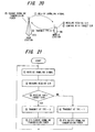
- Fig. 20 is a diagram for describing closed-loop transmission power control
- Fig. 21 is a flowchart of closed-loop transmission power control.
- TPC Transmission Power Control
- Fig. 22 is a diagram showing the frame structure of a dedicated physical channel DPCH in a downlink as standardized by the 3 rd Generation Partnership Project (referred to as "3GPP" below), and Fig. 23 is a diagram showing the frame structure of a dedicated physical channel DPCH in an uplink.
- 3GPP 3 rd Generation Partnership Project
- the downlink DPCH frame is such that one frame has a duration of 10 ms and is composed of 15 slots S 0 to S 14 .
- a DPDCH Dedicated Physical Data Channel
- DPCCH Dedicated Physical Control Channel
- the numbers of bits of PILOT, TPC and TFCI vary in dependence upon the symbol rate, and the numbers of bits vary as necessary even when the symbol rates are the same. In which slot format a transmission is performed is specified by the host prior to communication.
- the dedicated physical data channel DPDCH has 1 ⁇ a dedicated traffic channel DTCH and 2 ⁇ a dedicated control channel DCCH.
- the dedicated traffic channel DTCH is a channel that transmits dedicated traffic information between the mobile station and network
- the dedicated control channel DCCH is a channel used in the transmission of dedicated control information between the mobile station and network.
- a number of messages make up the dedicated control information, such as:
- the uplink DPCH frame is composed of a dedicated physical data channel DPDCH that transmits only transmit data and a dedicated physical control channel DPCCH that transmits control data such as Pilot, TPC, TFCI and FBI (Feedback Indicator), etc.
- DPCCH is spread by orthogonal code, the data is mapped onto a real axis (I axis) and imaginary axis (Q axis) and multiplexed.
- One frame of the uplink has a duration of 10 ms and is composed of 15 slots (slot #0 to slot #14).
- the number of bits per slot of the dedicated physical data channel DPDCH varies in dependence upon the symbol rate, but each slot of the dedicated physical control channel DPCCH is fixed at ten bits and the symbol rate is fixed at 15 ksps.
- Fig. 24 is a block diagram of the main components of the mobile station MS.
- a demodulating processor 1a in the modem MOD applies orthogonal detection and despread processing to a receive signal that enters from a radio unit RF, thereby demodulating the receiving signal.
- a receive-SIR measurement unit 1b measures the signal vs. interference noise ratio SIR, and a comparator 1c compares target SIR with the receive SIR and inputs the result of comparison to a TPC bit generator 1d.
- the target SIR which is a SIR value necessary in order to obtain an error rate of, e.g., 10 -3 (occurrence of error at a rate of once per 1000 times), is set in the comparator 1c from a channel codec CCD.
- a modulating processor 1e spread-spectrum modulates the dedicated physical data DPDCH (DTCH, DCCH) and the dedicated physical control data DPCCH (TFCI, TPC, Pilot, FBI) and applies a DA conversion and quadrature modulation after the spread-spectrum modulation.
- the radio unit RF applies processing such as a frequency conversion and power amplification and then transmits the resultant signal to the base station from an antenna.
- a base station BTS demodulates the TPC bits and control downlink transmission power in accordance with the "0", "1" logic of the TPC bits.
- the SIR that is necessary to obtain a desired quality (the block error rate, or BLER) is not constant.
- block error is observed and control is exercised to increase the target SIR if the observed value is inferior to the target BLER and decrease the target SIR if the observed value is superior to the target BLER.
- Control that thus changes the target SIR adaptively in order to achieve the desired quality is well known as open-loop transmission power control.
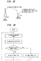
- Fig. 25 is a diagram for describing open-loop transmission power control
- Fig. 26 is a flowchart of open-loop transmission power control.
- the mobile station MS 1 ⁇ receives a downlink signal from the base station BTS, 2 ⁇ measures the block error rate BLER (receive BLER) of a dedicated physical channel during reception, and 3 ⁇ compares the receive BLER with a target BLER, which corresponds to the communication service reported from the host. 4 ⁇ If the receive BLER is superior to the target BLER, the mobile station instructs the modem MOD to lower the target SIR. If the receive BLER is inferior to the target BLER, then the mobile station instructs the modem MOD to raise the target SIR. The mobile station MS performs the above-describe open-loop control frame by frame.
- BLER block error rate BLER
- Open-loop power control processing is executed by the channel codec CCD (Fig. 24). That is, after the signal that has been transmitted from the base station BTS is demodulated by the demodulating processor 1a of the modem MOD, the signal is subjected to error correcting decoding by a decoding processor 2a and thenceforth is segmented into transport blocks TrBk. CRC error detection is subsequently carried out on a per-TrBk basis.
- a receive-BLER measurement unit 2b measures the receive BLER based upon the result of error detection of each transport block TrBk and inputs the receive BLER to a comparator 2c.
- the latter compares the receive BLER and the target BLER in terms of size, instructs the modem MOD to raise the target SIR if the receive BLER is larger than the target BLER and to lower the target SIR if the receive BLER is smaller than the target BLER.
- encoding is performed on the transmitting side in the manner shown in Fig. 27. Specifically, if a plurality (N) of transport blocks TrBk exist in a transmission time interval (TTI), a CRC add-on circuit generates a CRC (Cyclic Redundancy Code) error-detecting code for every transport block TrBk and adds this onto the transmit data.
- An encoder concatenates joins the N-number of transport blocks TrBk having the attached CRCs and encodes the blocks by error-correcting encoding such as convolutional coding or turbo coding.
- the decoding processor 2a subjects the receive data to error-correction decoding processing.
- CRC error detection is performed for every transport block TrBk of N transport blocks constituting the result of decoding and the result of error detection is input to the receive-BLER measurement unit 2b.
- the mobile station MS decides the target SIR mainly by the block error rate BLER of the dedicated traffic channel DTCH. Consequently, in a case where silence continues in a voice call, etc., there are occasions where the block error rate BLER of the dedicated traffic channel DTCH appears good and the target SIR continues to be lowered. If the dedicated control channel DCCH is introduced into the dedicated physical channel DPCH under these conditions, transmission power will be too low, quality sufficient to receive the dedicated control channel DCCH cannot be obtained and communication may be cut off. This tendency becomes particularly pronounced if interfering waves are present. Accordingly, it is necessary to control the target SIR so as to maintain enough quality to receive the dedicated control channel DCCH.
- a synchronization channel SCH appears to be an interference wave at a portion at which the synchronization channel SCH is superimposed.
- a problem which arises is that the reception quality of the dedicated control channel DCCH is degraded by interference of the synchronization channel SCH, the dedicated control data cannot be decoded correctly and communication is severed.
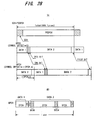
- (A) is a diagram useful in describing the positional relationship between the synchronization channel SCH and dedicated physical channel DPCH.
- SCH is a synchronization channel for cell search
- PCCPCH is a primary common control physical channel.
- the mobile station MS establishes spreading code synchronization on the downlink using the synchronization channel SCH, then decodes the reported channel information of the primary common control physical channel PCCPCH on the downlink and transmits a random-access channel RACH on the uplink at a transmission timing stipulated in advance.
- the base station BTS establishes spreading code synchronization on the uplink an decodes the RACH information. As a result, the uplink and downlink radio links are established.
- SCH + PCCPCH, DPCH are each transmitted from the base station BTS.
- the dedicated physical data channel DPDCH (the Data1, Data2 sections) of the dedicated physical channel DPCH has a dedicated traffic channel DTCH that transmits dedicated traffic information such as voice, and a dedicated control channel DCCH used in transmission of dedicated control information between the mobile station and network.
- a dedicated traffic channel DTCH that transmits dedicated traffic information such as voice
- a dedicated control channel DCCH used in transmission of dedicated control information between the mobile station and network.
- voice quality merely deteriorates and this does not result in a fatal flaw.
- the synchronization channel SCH overlaps the dedicated control channel DCCH the reception quality of the dedicated control information declines and there are instances where the dedicated control information can no longer be decoded correctly. This can result in a fatal situation in which communication is severed.
- an object of the present invention is to so arrange it that communication will not be severed even in a case where the positions of the dedicated control channel DCCH and synchronization channel SCH overlap.
- Another object of the present invention is to suppress a decline in reception quality of the dedicated control channel DCCH, which is ascribable to interference with the synchronization channel, while an improvement in reception quality that is more than necessary is suppressed.
- an open-loop power controller investigates whether a dedicated control channel DCCH and a synchronization channel SCH overlap based upon information reported from a higher layer and a receive TFCI. If the channels overlap, the open-loop power controller suspends ordinary open-loop power control processing, increases a target SIR by a satisfactory level and indicates this to a closed-loop power controller. The closed-loop power controller maintains the indicated target SIR until the end of DCCH reception and executes closed-loop transmission power control processing based upon the target SIR. The open-loop power controller resumes ordinary open-loop transmission power control processing after DCCH reception ends.
- the open-loop power controller is also capable of exercising control as follows if it is determined that the dedicated control channel DCCH and synchronization channel SCH overlap: If the dedicated control channel DCCH and synchronization channel SCH overlap, the open-loop power controller suspends ordinary open-loop power control processing, increases the target SIR a fixed level at a time frame by frame during DCCH reception and indicates this to the closed-loop power controller. The open-loop power controller resumes ordinary open-loop transmission power control processing after DCCH reception ends.
- the target SIR can be set higher than usual. In closed-loop power control processing, therefore, receive SIR becomes inferior to the target SIR. As a result, the base station is notified so as to raise the transmission power. If the base station raises the downlink transmission power, the DCCH reception quality is improved and communication will not be cut off. Further, target SIR is raised only if the dedicated control channel DCCH and synchronization channel SCH overlap. As a result, a decline in reception quality of the dedicated control channel DCCH, which is ascribable to interference with the synchronization channel, can be suppressed while an improvement in reception quality that is more than necessary is suppressed.
- Fig. 1 is a diagram useful in describing the protocol architecture of a radio interface in a W-CDMA system.
- the architecture includes three protocol layers, namely a physical layer (Layer 1), a data link layer (Layer 2) and a network layer (Layer 3).
- Layer 2 is further divided into a MAC (Medium Access Control) sublayer and RLC (Radio Link Control) sublayer.
- MAC Medium Access Control
- RLC Radio Link Control
- the channels of this radio interface are arranged in three hierarchical levels, namely physical channels, a transport channel and logical channels. These are classified according to the function and logical characteristics of the transmitted signal and are characterized by the information content transferred.
- the logical channels related to this invention are the dedicated control channel DCCH and the dedicated traffic channel DTCH.
- the transport channel is a channel provided to the MAC sublayer from the physical layer. There are transport channels of a plurality of types in order to transmit data of different characteristics and forms on the physical layer.
- the transport channel related to this invention is a dedicated channel DCH.
- the dedicated channel DCH is a bidirectional channel used in transmission of user data and is assigned individually to each mobile station.
- the physical channels are classified taking the function of the physical layer into consideration and are specified by spreading codes and frequency carriers, etc.
- the physical channels related to this invention are the dedicated physical channels (DPDCH, DPCCH) and the synchronization channel SCH for cell search.
- mapping of the logical channels (DTCH, DCCH) to the transport channel is carried out in the MAC sublayer, and the mapping of the transport channel to the physical channel is carried out in the physical layer.
- Fig. 2 is a block diagram of a mobile station.
- DTCH information Dedicated traffic information
- DCCH information dedicated control information
- TAF units terminal access function units
- TAF IF terminal access function interface
- TTI Transmission Time Interval
- TF Transport Format
- a TrCH demultiplexer 3a in the TAF IF 3 1 ⁇ refers to the information specified by the higher layer and verifies the TrCH on which each logical channel is connected, 2 ⁇ decides the transmit data length per TTI of each TrCH based upon the transmit bit rate of each logical channel and transport format TF of each TrCh, and 3 ⁇ demultiplexes the transmit data of each TrCH on a per-TTI basis and inputs the data to a channel codec 4.
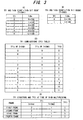
- (A) and (B) in Fig. 3 illustrate an example of a transport format TF in a case where dedicated traffic data (DTCH data) and dedicated control data (DCCH data) are multiplexed on TrCH#1 TrCH#2 and transmitted.
- Candidates of transport format TF of the TrCH#1 for DTCH are of six types (0 to 5) and have bit lengths per transmission time interval TTI of 0 ⁇ 336 bits, 1 ⁇ 336 bits, 2 ⁇ 336 bits, 4 ⁇ 336 bits, 8 ⁇ 336 bits and 12 ⁇ 336 bits, respectively.
- the transmission time interval TTI of TrCH#1 is 20 ms
- the transmission time interval TTI of TrCH#2 is 40 ms
- four frames of multiplexed data every 10 ms become combinations of TFIs of the kind shown at (D) in Fig. 3.
- the TFCIs are indicated in the column on the right side.
- the TrCH demultiplexer 3a in the TAF IF 3 demultiplexes the data of each logical channel every TTI based upon the decided TFI of each TrCH and inputs the data to the channel codec 4. Further, the TAF IF 3 also inputs the TFCI to the channel codec.
- the channel codec 4 executes, on a per-TrCH basis, error detection encoding processing (appending of CRC), error correction encoding processing, rate matching, primary interleaving and radio frame segmentation processing, etc.
- Radio frame segmentation processing is processing for segmenting the transmit data of one TTI of each TrCH frame by frame.
- the multiplexer of the channel codec 4 multiplexes the transmit data of each TrCH frame by frame, executes secondary interleave processing, etc., subsequently maps the multiplexed data onto the dedicated physical data channel DPDCH of the dedicated physical channel DPCH and inputs the data to a modulator (MOD) 5 as in-phase component data at a prescribed symbol rate.
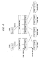
- Fig. 4 illustrates an example in which the two TrCH#1, TrCH#2 of TTI 20 ms and 40 ms are multiplexed and transmitted.
- TrCH#1-1 and TrCH#1-2 of first and second frames are the initial 20 ms of data of TrCH#1, and TrCH#1-3 and TrCH#1-4 of third and fourth frames are the next 20 ms of data of TrCH#1.
- the channel codec 4 When the data of each transport channel TrCH is multiplexed, mapped to a physical channel and transmitted, the channel codec 4 appends the parameter TFCI, which indicates how the encoded data of each transport channel TrCH has been multiplexed, to the physical channel data and transmits the result in such a manner that demultiplexing can be performed correctly on the receiving side.
- the channel codec 4 maps control data such as PILOT, TFCI and FBI to the dedicated physical control channel DPCCH and inputs the data to the modulator (MOD) 5 as quadrature-component data at fixed symbol rate.
- the TPC bits in the control data are inserted into the dedicated physical control channel DPCCH in the closed-loop controller of the MOD 5. Transmission power control will be described later.
- the modulator (MOD) 5 applies spread-spectrum modulation to the transmit data of DPDCH and control data of DPCCH using the prescribed spreading codes, applies a DA conversion and subsequently executes QPSK quadrature modulation.
- a radio transmitter 6 frequency-converts the quadrature-modulated signal to a high frequency, applies high-frequency amplification, etc., and transmits the resultant signal from an antenna ANT T .
- a radio receiver 7 frequency-converts a high-frequency signal received by an antenna ANT R to a baseband signal.
- a demodulator (DEM) 8 subjects the baseband signal to orthogonal detection, generates in-phase (I-phase) and quadrature-phase (Q-phase) signals, subjects each signal to an AD conversion, applies despread processing to the I-component and Q-component data using codes identical with the spreading codes, demodulates control data (PILOT, TFCI, FBI) and receive data and inputs the results to the channel codec 4.
- the latter demultiplexes the received multiplexed data per transport channel TrCH based upon the TFCI, subsequently executes deinterleaving, rate matching, error-correction decoding processing and CRC check processing, etc., on a per-TrCH basis, inputs the results to the TAF IF 3 and to each TAF unit via the TAF IF.
- Fig. 5 is a flowchart of channel coding and multiplex processing of downlink dedicated channel (DCH) of a base station. Processing similar to the channel coding and multiplex processing of the mobile station is executed.
- Downlink signals of the dedicated traffic channel (DTCH) and dedicated control channel (DCCH), etc., constituting the dedicated channel DCH undergo the following processing for every transport channel (TrCH): 1 ⁇ appending of CRC every transport block (TrBLK) ⁇ 2 ⁇ concatenating of transport blocks (TrBLK) having appended CRCs ⁇ 3 ⁇ channel coding (error correction encoding) ⁇ 4 ⁇ appending of tail bits ⁇ 5 ⁇ rate matching ⁇ 6 ⁇ first interleaving ⁇ 7 ⁇ radio frame segmentation.
- the DTCH, DCCH downlink signal is transmitted upon being subjected to the following processing in the order mentioned: 1 ⁇ transport channel multiplexing based upon a fixed position scheme or flexible position scheme ⁇ 2 ⁇ DTX (interval devoid of data) indicator insertion ⁇ 3 ⁇ physical channel segmentation ⁇ 4 ⁇ second interleaving ⁇ 5 ⁇ physical channel mapping.
- Fig. 6 illustrates an example of DTCH/DCCH radio frame segmentation.
- Data transmitted on the dedicated traffic channel DTCH is subjected to processing such as channel coding at fixed intervals (every TTI) and then is segmented into 10-ms frames.
- the TTI of the dedicated traffic channel DTCH is 20 ms and therefore segmentation is into two frames.
- the number of TrBLKs transmitted every TTI is any one of 0, 2, 4.
- the dedicated control channel DCCH also is segmented into 10-ms frames in a similar manner.
- the TTI of the dedicated control channel DCCH is 40 ms and therefore segmentation is into four frames.
- TrBLKs transport format information
- Fig. 7 is an example of DTCH/DCCH TrCH multiplexing.
- TrCH multiplexing one or a plurality of dedicated traffic channels DTCH and dedicated control channels DCCH are multiplexed, but there are two types of multiplexing methods.
- the first multiplexing method is the fixed position scheme, which fixes the position of the data on a per-TrCH basis and does not pack in data even in DTX sections.
- the second multiplexing method is the flexible position scheme, which does not fix the position of the data every TrCH and fills in only certain portions with data.
- the dedicated and flexible position schemes multiplexing is being performed is reported from the higher layer when the dedicated physical channel DPCH is open.
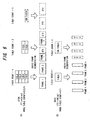
- Fig. 8 is a diagram useful in describing DTCH/DCCH second interleaving and physical channel mapping.
- the channel codec of the base station stores 1080 bits (b0 to b1079) of this multiplexed frame successively in an interleaving memory horizontally 30 bits at a time, as indicated at (B).
- the channel codec After storage is completed, the channel codec reads out and concatenates 36 bits of data in the vertical direction from two positions to which the same slot number (Slot #) has been assigned, thereby performing second interleaving.
- (C) indicates data of Slot #0, which is obtained by reading out and concatenating data from two positions (0A, 0B) of slot number 0, and data of Slot #1, which is obtained by reading out and concatenating data from two positions (1A, 1B) of slot number 1.
- TrCH multiplexing has the order of its bits interchanged in frame units and is segmented into slot units.
- the data of DCCH is placed at two locations in a slot by second interleaving.
- the channel codec of the base station maps DPDCH data of Slot #0 indicated at (C) to the Data1, Data2 portions of the downlink dedicated physical channel DPCH indicated at (D) [see (E)] and thenceforth successively maps the DPDCH data of Slots #1 to #15 to the Data1, Data2 portions of the downlink dedicated physical channel DPCH and transmits the result.
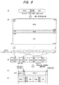
- Fig. 9 illustrates the positional relationship between the dedicated physical channel DPCH and synchronization channel SCH.
- the synchronization channel SCH is situated at the beginning 66.7 ⁇ s of every slot, as indicated at (A).
- the dedicated physical channel DPCH comprises data bits to which the DTCH or DCCH is mapped, a TPC bit for uplink transmission power control, a TFCI bit indicating the number of TrBLKs of DTCH/DCCH, and a Pilot bit for achieving synchronization.
- the data bits are further divided into two portions, namely Data1 and Data2.
- the slot format (number of bits of each item of data) of the dedicated physical channel DPCH differs depending the content of communication and is reported from the higher layer when the DPCH is opened. Further, there are cases where an offset (symbol offset) is present in a slot of the dedicated physical channel DPCH and in a slot of the synchronization channel SCH, as indicated at (C). The offset quantity ⁇ also is reported from the higher layer when the DPCH is open.
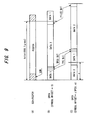
- Fig. 10 is a diagram useful in describing a DTCH/DCCH positional relationship that conforms to the number of TrBLKs of the dedicated traffic channel DTCH and the positional relationship of the synchronization channel SCH.
- TrCH multiplexing is by the flexible position scheme
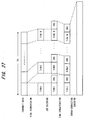
- TrCH multiplexing is carried out according to the flexible position scheme. If the symbol offset of the dedicated physical channel DPCH is zero, the DCCH at (A) and the synchronization channel SCH overlap and the dedicated control channel DCCH sustains interference from the synchronization channel SCH. Further, there are also cases where the synchronization channel SCH overlaps the DCCH indicated at (B), (C) in dependence upon the DPCH offset quantity ⁇ .
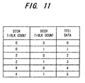
- the table is created as set forth below. Specifically, there are six possible combinations of TFIs of DTCH/DCCH (combinations of numbers of TrBLKs of DTCH/DCCH).
- the TFCI data varies every minimum TTI (20 ms in this case) in the multiplexed TrCH.
- the mobile station MS demodulates the TFCI from the receive information and can obtain the number of blocks of each TrCH, i.e., the number of TrBLKs of DTCH/DCCH, from this TFCI and the correspondence table (TFCI table) of Fig. 11.
- the first factor is a symbol offset of the dedicated physical channel DPCH with respect to the synchronization channel SCH, as evident from Fig. 10.
- the amount of the offset is reported from the higher layer when the DPCH is open.
- the second factor is the slot format of the downlink DPCH.
- TrCH multiplexing will be performed by the flexible position scheme in the manner illustrated at (B) in Fig. 13.
- TrCH multiplexed data 100A, 100B at (A) and (B) of Fig. 13 are compared with regard to a case where the number of TrBLKs of DTCH is four and the number of TrBLKs of DCCH is one at (A) and (B) of Fig. 13, then it will be understood that the DCCH positions are different. This is ascribable to a difference in transport format TF.
- the transport format TF is reported from the higher layer when the DPCH is open.
- the fourth factor is the number of DTCH blocks per frame, as will be evident from Fig. 10.
- the number of DTCH blocks per frame is found from the TFCI included in the receive data, the TFCI table (see Fig. 11) and the TTI reported from the higher layer when the DPCH is open.
- Fig. 14 is a block diagram of a mobile station MS having a closed-loop power controller and an open-loop power controller according to the present invention. Components identical with those of Fig. 2 are designated by like reference characters.
- a receiver-SIR measurement unit 11 measures the signal-to-interference power ratio SIR, and a comparator 12 compares the target SIR and the receive SIR and inputs the result of comparison to a TPC-bit inserting unit 13.
- the target SIR which is a SIR value necessary in order to obtain an error rate of, e.g., 10 -3 (occurrence of error at a rate of once per 1000 times), is set in the comparator 12 from the channel codec 4.
- the modulator 5 applies spread-spectrum modulation to the dedicated physical data channel DPDCH (DTCH, DCCH) output from the channel codec 4 and to the dedicated physical control channel DPCCH into which the TPC bits have been inserted, and applies a DA conversion and quadrature modulation after spread-spectrum modulation. Processing such as a frequency conversion and power amplification is applied by the radio unit 6, and the resultant signal is transmitted from the antenna ANT T to the base station.
- DPDCH dedicated physical data channel
- DCCH dedicated physical control channel
- Processing such as a frequency conversion and power amplification is applied by the radio unit 6, and the resultant signal is transmitted from the antenna ANT T to the base station.
- a decoding processor 21 applies error correction decoding processing and error detection processing to the receive signal that is output from the demodulator (DEM) 8, outputs the result of error detection to a receive-BLER measurement unit 22 and inputs the decoded TFCI is input to an SCH/DCCH overlap detector 23.
- DEM demodulator
- the receive-BLER measurement unit 22 measures the block error rate BLER (receive BLER) of the dedicated physical channel DPCH during reception and inputs the receive BLER to a target-SIR measurement unit 24.
- the SCH/DCCH overlap detector 23 monitors whether the synchronization channel SCH and dedicated control channel DCCH overlap and outputs a signal OVL indicating the result of monitoring.
- the SCH/DCCH overlap detector 23 obtains the CTFC, which corresponds to the TFCI that enters from the decoding processor 21, from a conversion table, calculates the TFI of each TrCH from the CTFC and then obtains the number of blocks and block-bit length per TTI on a per-TrCH basis from the transport format. Thereafter, the SCH/DCCH overlap detector 23 refers to the slot format to obtain the DCCH position in the slot and then checks to determine whether the dedicated control channel DCCH overlaps the synchronization channel SCH in terms of timing, taking into consideration the symbol offset.
- the target-SIR measurement unit 24 compares the receive BLER and the target BLER.
- the target-SIR measurement unit 24 lowers the level of the target SIR by one rank if the receive BLER is superior to the target BLER, raises the level of the target SIR if the receive BLER is inferior to the target BLER and inputs the changed target SIR to the closed-loop controller 10.
- the target-SIR measurement unit 24 performs the above-described open-loop control frame by frame.
- the target-SIR measurement unit 24 suspends the above-described open-loop control processing, increases the target SIR by a set level in such a manner that the dedicated control channel DCCH can be received satisfactorily even if interference is received from the synchronization channel SCH, or changes the target SIR to obtain a set level, and inputs the new target SIR to the closed-loop controller 10.
- the receive SIR becomes inferior to the target SIR and therefore the mobile station MS informs the base station BTS to raise the transmission power. The base station raises the transmission power, the reception quality of the dedicated control channel DCCH is improved and communication is no longer severed.
- the target-SIR measurement unit 24 fixes the target SIR at the set level irrespective of the receive BLER for the duration of the minimum TTI in all TrCHs during communication. Upon elapse of the minimum TTI, the target-SIR measurement unit 24 checks the signal OVL, maintains the target SIR at the set level if the SCH and DCCH are overlapping and resumes open-loop power control if the SCH and DCCH are not overlapping.
- the target SIR is raised only if the dedicated control channel DCCH and synchronization channel SCH overlap, a decline in reception quality of the dedicated control channel DCCH, which is ascribable to interference with the synchronization channel SCH, can be suppressed while an improvement in reception quality that is more than necessary is suppressed.
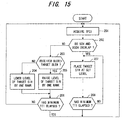
- Fig. 15 is a flowchart of first open-loop control processing according to the present invention.
- the SCH/DCCH overlap detector 23 acquires the TFCI from the decoding processor 21 every minimum TTI (step 201) and checks to determine whether the synchronization channel SCH and dedicated control channel DCCH overlap in terms of timing (step 202) using this TFCI and the slot format, transport format TF of each TrCH, transmission time interval TTI of each TrCH and TrCH multiplexing scheme, which are reported from the higher layer when the DPCH is open. If the synchronization channel SCH and the dedicated control channel DCCH are not overlapping, the target-SIR measurement unit 24 compares the receive BLER and the target BLER frame by frame (step S203).
- the target-SIR measurement unit 24 lowers the level of the target SIR (step 204) by one rank if the receive BLER is superior to the target BLER, raises the level of the target SIR (step 205) if the receive BLER is inferior to the target BLER and inputs the changed target SIR to the closed-loop controller 10. Thereafter, the target-SIR measurement unit 24 checks to see whether the minimum TTI has elapsed (step 206), repeats the processing from step 203 onward until the minimum TTI elapses and returns to step 201 when the minimum TTI elapses.
- the target-SIR measurement unit 24 increases and fixes the target SIR at the set level irrespective of the receive BLER (step 207) and thenceforth checks to see whether the minimum TTI has elapsed (step 208).
- the target-SIR measurement unit 24 fixes the target SIR at the set level until the minimum TTI elapses and returns to step 201 when the minimum TTI elapses.
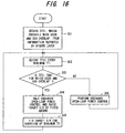
- Fig. 16 is a flowchart of second open-loop control processing according to the present invention.
- the SCH/DCCH overlap detector 23 obtains in advance and stores the TFCI that prevails in a case where the timings of the dedicated control channel DCCH and synchronization channel SCH overlap (step 301).
- the SCH/DCCH overlap detector 23 thenceforth acquires TFCI data from the decoding processor 21 every minimum TTI (step 302) and determines whether the acquired TFCI is the TFCI, which was found beforehand at step 301, prevailing in the case where the timings of the DCCH and SCH overlap (step 303). If the TFCI is the TFCI prevailing at overlap, the ordinary open-loop control processing is suspended, the target SIR is increased by an amount that enables the dedicated control channel DCCH to be received satisfactorily even if interference is received from the synchronization channel SCH, or the target SIR is increased to a set level, and the closed-loop controller 10 is instructed of the new target SIR (step 304). Thereafter, the target SIR is set (step 305), irrespective of the receive BLER, for the duration of the minimum TTI, after which the processing from step 302 onward is repeated.
- step 303 If the result of the determination at step 303 is that the TFCI is one prevailing when the dedicated control channel DCCH and synchronization channel SCH do not overlap, on the other hand, then ordinary open-loop power control processing is executed frame by frame (step 306), after which the processing from step 302 onward is repeated.
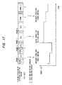
- Fig. 17 is a diagram useful in describing second open-loop control processing.
- Fig. 17 illustrates the manner in which target SIR varies in accordance with Fig. 12 in a case where TrCH#1 and TrCH#2 overlap.
- the amount of symbol offset is zero.
- the TFCI that prevails when the DCCH and SCH overlap in terms of timing is found when the DPCH is open.
- whether the SCH and DCCH overlap or not can be determined by simple processing that entails merely comparing the TFCI acquired every minimum TTI and the TFCI that prevails in case of overlap.
- Fig. 18 is a flowchart of third open-loop control processing according to the present invention.
- the SCH/DCCH overlap detector 23 obtains in advance and stores the TFCI that prevails in a case where the timings of the dedicated control channel DCCH and synchronization channel SCH overlap (step 401).
- the SCH/DCCH overlap detector 23 thenceforth acquires TFCI data from the decoding processor 21 every minimum TTI (step 402) and determines whether the acquired TFCI is the TFCI, which was found beforehand at step 401, prevailing in the case where the timings of the DCCH and SCH overlap (step 403). If the TFCI is the TFCI prevailing at overlap, the ordinary open-loop control processing is suspended, the target SIR is increased by a fixed amount ⁇ P irrespective of the target BLER and this is indicated to the closed-loop controller 10 (step 404). Control thenceforth returns to step 402.
- the target SIR is increased further by the fixed amount ⁇ P, this is indicated to the closed-loop controller 10 and control thenceforth returns to step 402. As a result, the target SIR is increased in stepwise fashion. It should be noted that ⁇ P is greater than an increase/decrease width ⁇ P' at the time of ordinary open-loop power control.
- step 403 If the result of the determination at step 403 is that the TFCI is one prevailing when there is no overlap, on the other hand, then ordinary open-loop power control processing is executed frame by frame (step 405), after which the processing from step 402 onward is repeated.
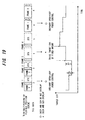
- Fig. 19 is a diagram useful in describing third open-loop control processing.
- Fig. 19 illustrates the manner in which target SIR varies in accordance with Fig. 12 in a case where TrCH#1 and TrCH#2 overlap.
- the amount of symbol offset is zero.
- the target SIR is increased stepwise rather than being increased at all once as in second open-loop control.
- a decline in reception quality of the DCCH can be suppressed while an improvement in reception quality that is more than necessary is suppressed.
Landscapes
- Engineering & Computer Science (AREA)
- Computer Networks & Wireless Communication (AREA)
- Signal Processing (AREA)
- Mobile Radio Communication Systems (AREA)
Abstract
An open-loop power controller of a transmission power control apparatus investigates whether a dedicated control channel DCCH and a synchronization channel SCH overlap. If the channels overlap, the open-loop power controller suspends ordinary open-loop power control processing, increases a target SIR by a satisfactory level and indicates this to a closed-loop power controller. The closed-loop power controller maintains the indicated target SIR and executes closed-loop transmission power control processing based upon the target SIR. The open-loop power controller resumes ordinary open-loop transmission power control processing after DCCH reception ends. <IMAGE>
Description
This invention relates to a power control method
and apparatus in a W-CDMA scheme. More particularly,
the invention relates to a power control method and
apparatus that take the positional relationship between
a downlink dedicated control channel and
synchronization channel into consideration to change
target quality for generating downlink transmission
power control (TPC) bits.
In CDMA mobile communications, multiple channels
are distinguished from one another by spreading codes
that are assigned to the channels, whereby a plurality
of channels perform communication sharing a single
frequency band. In an actual mobile communications
environment, however, a receive signal is susceptible
to interference from its own channel and from other
channels owing to delayed waves ascribable to multipath
fading and radio waves from other cells, and this
interference has an adverse influence upon channel
separation. Further, the amount of interference
sustained by a receive signal varies with time owing to
momentary fluctuations in reception power ascribable to
multipath fading and changes in the number of users
communicating simultaneously. In an environment in
which a receive signal is susceptible to noise that
varies with time in this fashion, it is difficult for
the quality of a receive signal in a mobile station
linked to a base station to be maintained at a desired
quality in a stable manner.
In order to follow up such a change in number of
interfering users and a momentary fluctuation caused by
multipath fading, closed-loop transmission power
control is carried out for exercising control in such a
manner that signal-to-interference ratio power (SIR) is
measured on the receiving side and the measured value
is compared with a target SIR, whereby SIR on the
receiving side will approach the target SIR.
Fig. 20 is a diagram for describing closed-loop
transmission power control, and Fig. 21 is a flowchart
of closed-loop transmission power control.
A mobile station MS 1 ○ receives a downlink signal
from a base station BTS, 2 ○ measures the SIR (receive
SIR) of a dedicated physical channel (DPCH) during
reception, and 3 ○ compares the receive SIR with target
SIR set by a host. 4 ○ The mobile station MS implements
TPC (Transmission Power Control) bit = 0 to direct the
base station BTS to lower transmission power if the
receive SIR is better than the target SIR, and
implements TPC bit = 1 to direct the base station BTS
to raise the transmission power if the receive SIR is
inferior to the target SIR. 5 ○ The base station BTS
controls the downlink transmission power based upon the
"0", "1" logic of the TPC bits received. Since the
mobile station MS performs the above-described power
control slot by slot, downlink transmission power can
be controlled at high speed.
Fig. 22 is a diagram showing the frame structure
of a dedicated physical channel DPCH in a downlink as
standardized by the 3rd Generation Partnership Project
(referred to as "3GPP" below), and Fig. 23 is a diagram
showing the frame structure of a dedicated physical
channel DPCH in an uplink.
As shown at (a) in Fig. 22, the downlink DPCH
frame is such that one frame has a duration of 10 ms
and is composed of 15 slots S0 to S14. A DPDCH
(Dedicated Physical Data Channel) for transmitting a
first data section Data1 and a second data section
Data2 and a DPCCH (Dedicated Physical Control Channel)
for transmitting a PILOT, TPC and TFCI are time-division
multiplexed slot by slot.
As shown at (b) in Fig. 22, the numbers of bits of
PILOT, TPC and TFCI vary in dependence upon the symbol
rate, and the numbers of bits vary as necessary even
when the symbol rates are the same. In which slot
format a transmission is performed is specified by the
host prior to communication.
The dedicated physical data channel DPDCH has 1 ○ a
dedicated traffic channel DTCH and 2 ○ a dedicated
control channel DCCH. The dedicated traffic channel
DTCH is a channel that transmits dedicated traffic
information between the mobile station and network, and
the dedicated control channel DCCH is a channel used in
the transmission of dedicated control information
between the mobile station and network. A number of
messages make up the dedicated control information,
such as:
As shown in Fig. 23, the uplink DPCH frame is
composed of a dedicated physical data channel DPDCH
that transmits only transmit data and a dedicated
physical control channel DPCCH that transmits control
data such as Pilot, TPC, TFCI and FBI (Feedback
Indicator), etc. After the data on the channels DPDCH,
DPCCH is spread by orthogonal code, the data is mapped
onto a real axis (I axis) and imaginary axis (Q axis)
and multiplexed. One frame of the uplink has a
duration of 10 ms and is composed of 15 slots (slot # 0
to slot #14). The number of bits per slot of the
dedicated physical data channel DPDCH varies in
dependence upon the symbol rate, but each slot of the
dedicated physical control channel DPCCH is fixed at
ten bits and the symbol rate is fixed at 15 ksps.
The above-described closed-loop transmission power
control is carried out in a modem MOD of the mobile
station MS. Fig. 24 is a block diagram of the main
components of the mobile station MS. A demodulating
processor 1a in the modem MOD applies orthogonal
detection and despread processing to a receive signal
that enters from a radio unit RF, thereby demodulating
the receiving signal. A receive-SIR measurement unit
1b measures the signal vs. interference noise ratio SIR,
and a comparator 1c compares target SIR with the
receive SIR and inputs the result of comparison to a
TPC bit generator 1d. The TPC bit generator 1d
executes TPC bit = 0 if the receive SIR is greater than
the target SIR and executes bit = 1 if the receive SIR
is less than the target SIR. The target SIR, which is
a SIR value necessary in order to obtain an error rate
of, e.g., 10-3 (occurrence of error at a rate of once
per 1000 times), is set in the comparator 1c from a
channel codec CCD. A modulating processor 1e spread-spectrum
modulates the dedicated physical data DPDCH
(DTCH, DCCH) and the dedicated physical control data
DPCCH (TFCI, TPC, Pilot, FBI) and applies a DA
conversion and quadrature modulation after the spread-spectrum
modulation. The radio unit RF applies
processing such as a frequency conversion and power
amplification and then transmits the resultant signal
to the base station from an antenna. A base station
BTS demodulates the TPC bits and control downlink
transmission power in accordance with the "0", "1"
logic of the TPC bits.
Owing to changes in traveling velocity during
communication and changes in the propagation
environment ascribable to travel, the SIR that is
necessary to obtain a desired quality (the block error
rate, or BLER) is not constant. In order to deal with
these changes, block error is observed and control is
exercised to increase the target SIR if the observed
value is inferior to the target BLER and decrease the
target SIR if the observed value is superior to the
target BLER. Control that thus changes the target SIR
adaptively in order to achieve the desired quality is
well known as open-loop transmission power control.
Fig. 25 is a diagram for describing open-loop
transmission power control, and Fig. 26 is a flowchart
of open-loop transmission power control.
The mobile station MS 1 ○ receives a downlink
signal from the base station BTS, 2 ○ measures the block
error rate BLER (receive BLER) of a dedicated physical
channel during reception, and 3 ○ compares the receive
BLER with a target BLER, which corresponds to the
communication service reported from the host. 4 ○ If
the receive BLER is superior to the target BLER, the
mobile station instructs the modem MOD to lower the
target SIR. If the receive BLER is inferior to the
target BLER, then the mobile station instructs the
modem MOD to raise the target SIR. The mobile station
MS performs the above-describe open-loop control frame
by frame.
Open-loop power control processing is executed by
the channel codec CCD (Fig. 24). That is, after the
signal that has been transmitted from the base station
BTS is demodulated by the demodulating processor 1a of
the modem MOD, the signal is subjected to error
correcting decoding by a decoding processor 2a and
thenceforth is segmented into transport blocks TrBk.
CRC error detection is subsequently carried out on a
per-TrBk basis. A receive-BLER measurement unit 2b
measures the receive BLER based upon the result of
error detection of each transport block TrBk and inputs
the receive BLER to a comparator 2c. The latter
compares the receive BLER and the target BLER in terms
of size, instructs the modem MOD to raise the target
SIR if the receive BLER is larger than the target BLER
and to lower the target SIR if the receive BLER is
smaller than the target BLER.
In W-CDMA as currently standardized, encoding is
performed on the transmitting side in the manner shown
in Fig. 27. Specifically, if a plurality (N) of
transport blocks TrBk exist in a transmission time
interval (TTI), a CRC add-on circuit generates a CRC
(Cyclic Redundancy Code) error-detecting code for every
transport block TrBk and adds this onto the transmit
data. An encoder concatenates joins the N-number of
transport blocks TrBk having the attached CRCs and
encodes the blocks by error-correcting encoding such as
convolutional coding or turbo coding. On the receiving
side the decoding processor 2a subjects the receive
data to error-correction decoding processing. Next,
CRC error detection is performed for every transport
block TrBk of N transport blocks constituting the
result of decoding and the result of error detection is
input to the receive-BLER measurement unit 2b.
In open-loop power control processing, the mobile
station MS decides the target SIR mainly by the block
error rate BLER of the dedicated traffic channel DTCH.
Consequently, in a case where silence continues in a
voice call, etc., there are occasions where the block
error rate BLER of the dedicated traffic channel DTCH
appears good and the target SIR continues to be lowered.
If the dedicated control channel DCCH is introduced
into the dedicated physical channel DPCH under these
conditions, transmission power will be too low, quality
sufficient to receive the dedicated control channel
DCCH cannot be obtained and communication may be cut
off. This tendency becomes particularly pronounced if
interfering waves are present. Accordingly, it is
necessary to control the target SIR so as to maintain
enough quality to receive the dedicated control channel
DCCH.
Further, with a W-CDMA scheme, ordinarily there is
no interference between different channels because
spreading is carried out using channelization codes
that are mutually orthogonal. With regard to a
synchronization channel, however, channelization codes
are not used. Consequently, when viewed from another
channel, a synchronization channel SCH appears to be an
interference wave at a portion at which the
synchronization channel SCH is superimposed. In
particular, at a portion where the timings of the
dedicated control channel DCCH in the dedicated
physical channel DPCH and of the synchronization
channel SCH overlap, a problem which arises is that the
reception quality of the dedicated control channel DCCH
is degraded by interference of the synchronization
channel SCH, the dedicated control data cannot be
decoded correctly and communication is severed.
In Fig. 28, (A) is a diagram useful in describing
the positional relationship between the synchronization
channel SCH and dedicated physical channel DPCH. In
the Figure, SCH is a synchronization channel for cell
search, and PCCPCH is a primary common control physical
channel. In a W-CDMA scheme, when a radio link is
connected between the base station BTS and mobile
station MS, the mobile station MS performs a cell
search using the synchronization channel SCH
transmitted by the base station BTS. More specifically,
the mobile station MS establishes spreading code
synchronization on the downlink using the
synchronization channel SCH, then decodes the reported
channel information of the primary common control
physical channel PCCPCH on the downlink and transmits a
random-access channel RACH on the uplink at a
transmission timing stipulated in advance. The base
station BTS establishes spreading code synchronization
on the uplink an decodes the RACH information. As a
result, the uplink and downlink radio links are
established.
The period of SCH + PCCPCH is one slot interval
(= 666.7 µs), which is the same as that of the
dedicated physical channel DPCH. SCH + PCCPCH, DPCH
are each transmitted from the base station BTS. The
relationship between SCH + PCCPCH and the dedicated
physical channel DPCH in cases where symbol offset = 0
and symbol offset = τDPCH, n hold is illustrated at (A)
of Fig. 28.
As shown at (B) in Fig. 28, the dedicated physical
data channel DPDCH (the Data1, Data2 sections) of the
dedicated physical channel DPCH has a dedicated traffic
channel DTCH that transmits dedicated traffic
information such as voice, and a dedicated control
channel DCCH used in transmission of dedicated control
information between the mobile station and network. In
a case where the synchronization channel SCH overlaps
the dedicated traffic channel DTCH, voice quality
merely deteriorates and this does not result in a fatal
flaw. However, if the synchronization channel SCH
overlaps the dedicated control channel DCCH, the
reception quality of the dedicated control information
declines and there are instances where the dedicated
control information can no longer be decoded correctly.
This can result in a fatal situation in which
communication is severed.
Accordingly, an object of the present invention is
to so arrange it that communication will not be severed
even in a case where the positions of the dedicated
control channel DCCH and synchronization channel SCH
overlap.
Another object of the present invention is to
suppress a decline in reception quality of the
dedicated control channel DCCH, which is ascribable to
interference with the synchronization channel, while an
improvement in reception quality that is more than
necessary is suppressed.
In a transmission power control apparatus
according to the present invention, an open-loop power
controller investigates whether a dedicated control
channel DCCH and a synchronization channel SCH overlap
based upon information reported from a higher layer and
a receive TFCI. If the channels overlap, the open-loop
power controller suspends ordinary open-loop power
control processing, increases a target SIR by a
satisfactory level and indicates this to a closed-loop
power controller. The closed-loop power controller
maintains the indicated target SIR until the end of
DCCH reception and executes closed-loop transmission
power control processing based upon the target SIR.
The open-loop power controller resumes ordinary open-loop
transmission power control processing after DCCH
reception ends.
Further, the open-loop power controller is also
capable of exercising control as follows if it is
determined that the dedicated control channel DCCH and
synchronization channel SCH overlap: If the dedicated
control channel DCCH and synchronization channel SCH
overlap, the open-loop power controller suspends
ordinary open-loop power control processing, increases
the target SIR a fixed level at a time frame by frame
during DCCH reception and indicates this to the closed-loop
power controller. The open-loop power controller
resumes ordinary open-loop transmission power control
processing after DCCH reception ends.
Thus, if the dedicated control channel DCCH and
synchronization channel SCH overlap, the target SIR can
be set higher than usual. In closed-loop power control
processing, therefore, receive SIR becomes inferior to
the target SIR. As a result, the base station is
notified so as to raise the transmission power. If the
base station raises the downlink transmission power,
the DCCH reception quality is improved and
communication will not be cut off. Further, target SIR
is raised only if the dedicated control channel DCCH
and synchronization channel SCH overlap. As a result,
a decline in reception quality of the dedicated control
channel DCCH, which is ascribable to interference with
the synchronization channel, can be suppressed while an
improvement in reception quality that is more than
necessary is suppressed.
Fig. 1 is a diagram useful in describing the
protocol architecture of a radio interface in a W-CDMA
system. The architecture includes three protocol
layers, namely a physical layer (Layer 1), a data link
layer (Layer 2) and a network layer (Layer 3). Layer 2
is further divided into a MAC (Medium Access Control)
sublayer and RLC (Radio Link Control) sublayer.
The channels of this radio interface are arranged
in three hierarchical levels, namely physical channels,
a transport channel and logical channels. These are
classified according to the function and logical
characteristics of the transmitted signal and are
characterized by the information content transferred.
The logical channels related to this invention are the
dedicated control channel DCCH and the dedicated
traffic channel DTCH. The transport channel is a
channel provided to the MAC sublayer from the physical
layer. There are transport channels of a plurality of
types in order to transmit data of different
characteristics and forms on the physical layer. The
transport channel related to this invention is a
dedicated channel DCH. The dedicated channel DCH is a
bidirectional channel used in transmission of user data
and is assigned individually to each mobile station.
The physical channels are classified taking the
function of the physical layer into consideration and
are specified by spreading codes and frequency carriers,
etc. The physical channels related to this invention
are the dedicated physical channels (DPDCH, DPCCH) and
the synchronization channel SCH for cell search.
The mapping of the logical channels (DTCH, DCCH)
to the transport channel is carried out in the MAC
sublayer, and the mapping of the transport channel to
the physical channel is carried out in the physical
layer.
Fig. 2 is a block diagram of a mobile station.
Dedicated traffic information (DTCH information) and
dedicated control information (DCCH information) that
has been mapped to a prescribed logical channel and
transmitted from a plurality of terminal access
function units (abbreviated to "TAF units" below) 1a to
In and a host application 2 is compiled in a terminal
access function interface (TAF IF) 3 that separates and
combines data. Information necessary for encoding
processing and multiplex transmission, such as 1 ○ the
connection relationship between the logical channel and
transport channel (TrCH), 2 ○ the encoding scheme of
each transport channel TrCH, 3 ○ the TTI (Transmission
Time Interval) of each transport channel TrCH and 4 ○
the TF (Transport Format) of each TrCH, has been
specified in the TAF IF 3 from a higher layer.
Furthermore, the transmission time intervals TTI
stipulated in W-CDMA are 10 ms, 20 ms, 40 ms and 80 ms.
A TrCH demultiplexer 3a in the TAF IF 3 1 ○ refers
to the information specified by the higher layer and
verifies the TrCH on which each logical channel is
connected, 2 ○ decides the transmit data length per TTI
of each TrCH based upon the transmit bit rate of each
logical channel and transport format TF of each TrCh,
and 3 ○ demultiplexes the transmit data of each TrCH on
a per-TTI basis and inputs the data to a channel codec
4.
The transport format TF specifies a bit-length
(= transport block count × block length) candidate per
TTI of each TrCH. For example, (A) and (B) in Fig. 3
illustrate an example of a transport format TF in a
case where dedicated traffic data (DTCH data) and
dedicated control data (DCCH data) are multiplexed on
TrCH# 1 TrCH# 2 and transmitted. Candidates of
transport format TF of the TrCH# 1 for DTCH are of six
types (0 to 5) and have bit lengths per transmission
time interval TTI of 0 × 336 bits, 1 × 336 bits, 2 ×
336 bits, 4 × 336 bits, 8 × 336 bits and 12 × 336 bits,
respectively. The TFIs Transport Format Indicators)
are 0, 1, 2, 3, 4 and 5, respectively. Further,
dandidates of transport format TF of the TrCH# 2 for
DCCH are of two types (0 and 1) and have bit lengths
per TTI of 0 × 148 bits and 1 × 148 bits, respectively.
The TFIs are 0 and 1, respectively. Combinations of
transport formats TF of TrCh# 1, TrCh# 2 are 12 (= 6 × 2)
in all, as illustrated at (C) of Fig. 3. A TFCI
(Transport Format Combination Indicator) is appended to
each combination. If the transmission time interval
TTI of TrCH# 1 is 20 ms, the transmission time interval
TTI of TrCH# 2 is 40 ms, data of which the number of
bits per TTI (= 20 ms) is 2 × 336 bits and data of
which the number of bits per TTI (= 20 ms) is
1 × 336 bits is transmitted successively from TrCH# 1
and data of which the number of bits per TTI (= 40 ms)
is 1 × 148 bits is transmitted successively from TrCH# 2,
then four frames of multiplexed data every 10 ms become
combinations of TFIs of the kind shown at (D) in Fig. 3.
The TFCIs are indicated in the column on the right side.
The TrCH demultiplexer 3a in the TAF IF 3
demultiplexes the data of each logical channel every
TTI based upon the decided TFI of each TrCH and inputs
the data to the channel codec 4. Further, the TAF IF 3
also inputs the TFCI to the channel codec.
The channel codec 4 executes, on a per-TrCH basis,
error detection encoding processing (appending of CRC),
error correction encoding processing, rate matching,
primary interleaving and radio frame segmentation
processing, etc. Radio frame segmentation processing
is processing for segmenting the transmit data of one
TTI of each TrCH frame by frame. In the example at (D)
in Fig. 3, the data of 2 × 336 bits in the initial TTI
= 20 ms of TrCH# 1 is segmented (2 × 336)/2 bits at a
time and assigned to first and second frames, and the
data of 1 × 336 bits in the next TTI = 20 ms is
segmented (1 × 336)/2 bits at a time and assigned to
third and fourth frames. Further, the data of 1 × 148
bits in TTI = 40 ms of TrCH# 2 is segmented (1 × 148)/4
bits at a time and assigned to the first to fourth
frames.
If radio frame segmentation processing is
completed on each TrCH, then the multiplexer of the
channel codec 4 multiplexes the transmit data of each
TrCH frame by frame, executes secondary interleave
processing, etc., subsequently maps the multiplexed
data onto the dedicated physical data channel DPDCH of
the dedicated physical channel DPCH and inputs the data
to a modulator (MOD) 5 as in-phase component data at a
prescribed symbol rate. Fig. 4 illustrates an example
in which the two TrCH# 1, TrCH# 2 of TTI 20 ms and 40 ms
are multiplexed and transmitted. In Fig. 4, TrCH#1-1
and TrCH#1-2 of first and second frames are the initial
20 ms of data of TrCH# 1, and TrCH#1-3 and TrCH#1-4 of
third and fourth frames are the next 20 ms of data of
TrCH# 1.
When the data of each transport channel TrCH is
multiplexed, mapped to a physical channel and
transmitted, the channel codec 4 appends the parameter
TFCI, which indicates how the encoded data of each
transport channel TrCH has been multiplexed, to the
physical channel data and transmits the result in such
a manner that demultiplexing can be performed correctly
on the receiving side. Specifically, the channel codec
4 maps control data such as PILOT, TFCI and FBI to the
dedicated physical control channel DPCCH and inputs the
data to the modulator (MOD) 5 as quadrature-component
data at fixed symbol rate. The TPC bits in the control
data are inserted into the dedicated physical control
channel DPCCH in the closed-loop controller of the MOD
5. Transmission power control will be described later.
The modulator (MOD) 5 applies spread-spectrum
modulation to the transmit data of DPDCH and control
data of DPCCH using the prescribed spreading codes,
applies a DA conversion and subsequently executes QPSK
quadrature modulation. A radio transmitter 6
frequency-converts the quadrature-modulated signal to a
high frequency, applies high-frequency amplification,
etc., and transmits the resultant signal from an
antenna ANTT.
At the time of reception, a radio receiver 7
frequency-converts a high-frequency signal received by
an antenna ANTR to a baseband signal. Thereafter a
demodulator (DEM) 8 subjects the baseband signal to
orthogonal detection, generates in-phase (I-phase) and
quadrature-phase (Q-phase) signals, subjects each
signal to an AD conversion, applies despread processing
to the I-component and Q-component data using codes
identical with the spreading codes, demodulates control
data (PILOT, TFCI, FBI) and receive data and inputs the
results to the channel codec 4. The latter
demultiplexes the received multiplexed data per
transport channel TrCH based upon the TFCI,
subsequently executes deinterleaving, rate matching,
error-correction decoding processing and CRC check
processing, etc., on a per-TrCH basis, inputs the
results to the TAF IF 3 and to each TAF unit via the
TAF IF.
Fig. 5 is a flowchart of channel coding and
multiplex processing of downlink dedicated channel
(DCH) of a base station. Processing similar to the
channel coding and multiplex processing of the mobile
station is executed. Downlink signals of the dedicated
traffic channel (DTCH) and dedicated control channel
(DCCH), etc., constituting the dedicated channel DCH
undergo the following processing for every transport
channel (TrCH): 1 ○ appending of CRC every transport
block (TrBLK) → 2 ○ concatenating of transport blocks
(TrBLK) having appended CRCs → 3 ○ channel coding
(error correction encoding) → 4 ○ appending of tail
bits → 5 ○ rate matching → 6 ○ first interleaving → 7 ○
radio frame segmentation.
The DTCH, DCCH downlink signal is transmitted upon
being subjected to the following processing in the
order mentioned: 1 ○ transport channel multiplexing
based upon a fixed position scheme or flexible position
scheme → 2 ○ DTX (interval devoid of data) indicator
insertion → 3 ○ physical channel segmentation → 4 ○
second interleaving → 5 ○ physical channel mapping.
Fig. 6 illustrates an example of DTCH/DCCH radio
frame segmentation. Data transmitted on the dedicated
traffic channel DTCH is subjected to processing such as
channel coding at fixed intervals (every TTI) and then
is segmented into 10-ms frames. In the example at (A)
of Fig. 6, the TTI of the dedicated traffic channel
DTCH is 20 ms and therefore segmentation is into two
frames. Further, the dedicated traffic channel DTCH is
such that the number of TrBLKs varies in dependence
upon the amount of transmit data every TTI (= 20 ms),
and the number of TrBLKs capable of being transmitted
in one TTI is reported from the higher layer. In the
example at (A) of Fig. 6, the number of TrBLKs
transmitted every TTI is any one of 0, 2, 4.
In a case where the maximum number (= 4) of TrBLKs
is transmitted, two transport blocks TrBLK are assigned
to each of two frames in the TTI (= 20 ms), and each
frame is filled entirely with transmit data. However,
if the number of transmit TrBLKs is not the maximum
number (= 4), then an interval (the DTX section) devoid
of data is produced in accordance with the ratio. In
the example at (A) in Fig. 6, half of each frame is DTX
when the number of TrBLKs is two, and the entirety of
each frame is DTX when the number of TrBLKs is zero.
The dedicated control channel DCCH also is
segmented into 10-ms frames in a similar manner. In
the example at (B) in Fig. 6, the TTI of the dedicated
control channel DCCH is 40 ms and therefore
segmentation is into four frames. Further, when the
number of TrBLKs is the maximum number (= 1), then the
number of TrBLKs transmitted in each frame becomes 1/4
and each frame is filled entirely with transmit data.
However, when the number of TrBLKs is zero, the
entirety of each frame is DTX.
Each TTI length and number of TrBLKs (transport
format information), etc., capable of being handled
every TTI on DTCH/DCCH is reported from the higher
layer when the DPCH is open.
Fig. 7 is an example of DTCH/DCCH TrCH
multiplexing. In TrCH multiplexing, one or a plurality
of dedicated traffic channels DTCH and dedicated
control channels DCCH are multiplexed, but there are
two types of multiplexing methods. The first
multiplexing method is the fixed position scheme, which
fixes the position of the data on a per-TrCH basis and
does not pack in data even in DTX sections. The second
multiplexing method is the flexible position scheme,
which does not fix the position of the data every TrCH
and fills in only certain portions with data.
Fig. 7 illustrates how TrCH multiplexing is
performed by each of these schemes in a case where the
number of TrBLKs of the dedicated traffic channel DTCH
changes in the manner 2 → 0 → 4 every TTI (= 20 ms)
and the number of TrBLKs of the dedicated control
channel DCCH changes in the manner 1 → 0 every TTI (=
40 ms). In which of the fixed and flexible position
schemes multiplexing is being performed is reported
from the higher layer when the dedicated physical
channel DPCH is open.
Fig. 8 is a diagram useful in describing DTCH/DCCH
second interleaving and physical channel mapping. A
multiplexed frame at (A) is obtained by segmenting DTCH
data of TrCH# 1 at 1 TTI = 20 ms, TrBLK count = 2 and
DCCH data of TrCH# 2 at 1 TTI = 40 ms, TrBLK count = 1
in Fig. 7 on a per-frame basis and performing
multiplexing based upon the flexible position scheme.
The channel codec of the base station stores 1080 bits
(b0 to b1079) of this multiplexed frame successively in
an interleaving memory horizontally 30 bits at a time,
as indicated at (B). After storage is completed, the
channel codec reads out and concatenates 36 bits of
data in the vertical direction from two positions to
which the same slot number (Slot #) has been assigned,
thereby performing second interleaving. (C) indicates
data of Slot # 0, which is obtained by reading out and
concatenating data from two positions (0A, 0B) of slot
number 0, and data of Slot # 1, which is obtained by
reading out and concatenating data from two positions
(1A, 1B) of slot number 1. As a result, the data that
has undergone TrCH multiplexing has the order of its
bits interchanged in frame units and is segmented into
slot units. The data of DCCH is placed at two
locations in a slot by second interleaving.
At the time of physical-channel mapping, the
channel codec of the base station maps DPDCH data of
Slot # 0 indicated at (C) to the Data1, Data2 portions
of the downlink dedicated physical channel DPCH
indicated at (D) [see (E)] and thenceforth successively
maps the DPDCH data of Slots # 1 to #15 to the Data1,
Data2 portions of the downlink dedicated physical
channel DPCH and transmits the result.
Fig. 9 illustrates the positional relationship
between the dedicated physical channel DPCH and
synchronization channel SCH. The synchronization
channel SCH is situated at the beginning 66.7 µs of
every slot, as indicated at (A). As indicated at (B),
the dedicated physical channel DPCH comprises data bits
to which the DTCH or DCCH is mapped, a TPC bit for
uplink transmission power control, a TFCI bit
indicating the number of TrBLKs of DTCH/DCCH, and a
Pilot bit for achieving synchronization. The data bits
are further divided into two portions, namely Data1 and
Data2.
The slot format (number of bits of each item of
data) of the dedicated physical channel DPCH differs
depending the content of communication and is reported
from the higher layer when the DPCH is opened. Further,
there are cases where an offset (symbol offset) is
present in a slot of the dedicated physical channel
DPCH and in a slot of the synchronization channel SCH,
as indicated at (C). The offset quantity τ also is
reported from the higher layer when the DPCH is open.
Fig. 10 is a diagram useful in describing a
DTCH/DCCH positional relationship that conforms to the
number of TrBLKs of the dedicated traffic channel DTCH
and the positional relationship of the synchronization
channel SCH. In a case where TrCH multiplexing is by
the flexible position scheme, the position of the DCCH
in the slot varies depending upon the number of TrBLKs
of the DTCH, as shown in Fig. 7, and is separated into
two location by interleaving. Accordingly, 1 ○ in a
case where TrBLK count = 0 holds in the DTCH, the
position of the DCCH in the slot is present at the
position indicated at (A) in Fig. 10; 2 ○ in a case
where TrBLK count = 2 holds in the DTCH, the position
of the DCCH in the slot is present at the position
indicated at (B) in Fig. 10; and 3 ○ in a case where
TrBLK count = 4 holds in the DTCH, the position of the
DCCH in the slot is present at the position indicated
at (C) in Fig. 10. Since the synchronization channel
SCH is present at the position indicated at (D), TrCH
multiplexing is carried out according to the flexible
position scheme. If the symbol offset of the dedicated
physical channel DPCH is zero, the DCCH at (A) and the
synchronization channel SCH overlap and the dedicated
control channel DCCH sustains interference from the
synchronization channel SCH. Further, there are also
cases where the synchronization channel SCH overlaps
the DCCH indicated at (B), (C) in dependence upon the
DPCH offset quantity τ.
Fig. 11 is a table indicating the relationship
between TFCI and number of TrBLKs of DTCH/DCCH in a
case where the numbers of DTCH blocks of TrCH# 1 at TTI
= 20 ms are 0, 2, 4 and the numbers of DCCH blocks of
TrCH# 2 at TTI = 40 ms are 0, 1. The table is created
as set forth below. Specifically, there are six
possible combinations of TFIs of DTCH/DCCH
(combinations of numbers of TrBLKs of DTCH/DCCH). The
CTFC (Calculated Transport Format Combination) is
calculated using a prescribed calculation formula with
regard to each combination and the TFCI (= 0 to 5)
conforming to this CTFC is obtained from the CTFC·TFCI
correspondence table, thereby creating the above-described
table.
Fig. 12 is a diagram useful in describing an
example of a change in TFCI. This illustrates a change
in TFCI in an instance where multiplexing has been
performed in accordance with the flexible position
scheme in a case where the number of TrBLKs of the
dedicated traffic channel DTCH varies in the manner 2
→ 0 → 4 every TTI (= 20 ms) and the number of TrBLKs
of the dedicated control channel DCCH varies in the
manner 1 → 0 every TTI (= 40 ms). The TFCI data
varies every minimum TTI (20 ms in this case) in the
multiplexed TrCH. Since this TFCI has been mapped to a
prescribed position of the DPCH, the mobile station MS
demodulates the TFCI from the receive information and
can obtain the number of blocks of each TrCH, i.e., the
number of TrBLKs of DTCH/DCCH, from this TFCI and the
correspondence table (TFCI table) of Fig. 11.
The following four factors are considered to be
behind the overlapping of the synchronization channel
SCH and dedicated control channel DCCH:
The first factor is a symbol offset of the
dedicated physical channel DPCH with respect to the
synchronization channel SCH, as evident from Fig. 10.
The amount of the offset is reported from the higher
layer when the DPCH is open.
The second factor is the slot format of the
downlink DPCH. There are 17 types of slot formats of
the downlink DPCH, as illustrated in Fig. 22, and the
bit lengths of Data1, Data1 and bit lengths of
TPI/PFCI/Pilot differ in each format. Consequently,
even if the DCCH data position after interleaving at
(C) of Fig. 8 is the same, the position in the slot of
the DCCH data mapped to Data1 Data2 changes when the
slot format is changed. Owing to this change in
position, a situation in which the dedicated control
channel DCCH overlaps the synchronization channel SCH
arises. Which slot format will be used depends upon
the amount of transmit data, and the slot format used
is reported from the higher layer when the DPCH is open.
The third factor is the transport format of each
TrCH. If it is assumed that numbers of DTCH blocks of
TrCH# 1 at TTI = 20 ms are 0, 2, 4 and the numbers of
DCCH blocks of TrCH# 2 at TTI = 40 ms are 0, 1, that the
number of DTCH blocks of TrCH# 1 varies in the manner 0
→ 2 → 4 every 20 ms and that the number of DCCH
blocks of TrCH# 2 varies in the manner 1 → 1 every 40
ms, then TrCH multiplexing will be performed by the
flexible position scheme in the manner illustrated at
(A) in Fig. 13.
On the other hand, if it is assumed that numbers
of DTCH blocks of TrCH# 1 at TTI = 20 ms are 0, 2, 4, 8
and the numbers of DCCH blocks of TrCH# 2 at TTI = 40 ms
are 0, 1, that the number of TrBLKs of TrCH# 1 varies in
the manner 0 → 4 → 8 every 20 ms and that the number
of TrBLKs of TrCH# 2 varies in the manner 1 → 1 every
40 ms, then TrCH multiplexing will be performed by the
flexible position scheme in the manner illustrated at
(B) in Fig. 13.
If TrCH multiplexed data 100A, 100B at (A) and (B)
of Fig. 13 are compared with regard to a case where the
number of TrBLKs of DTCH is four and the number of
TrBLKs of DCCH is one at (A) and (B) of Fig. 13, then
it will be understood that the DCCH positions are
different. This is ascribable to a difference in
transport format TF. The transport format TF is
reported from the higher layer when the DPCH is open.
The fourth factor is the number of DTCH blocks per
frame, as will be evident from Fig. 10. The number of
DTCH blocks per frame is found from the TFCI included
in the receive data, the TFCI table (see Fig. 11) and
the TTI reported from the higher layer when the DPCH is
open.
Fig. 14 is a block diagram of a mobile station MS
having a closed-loop power controller and an open-loop
power controller according to the present invention.
Components identical with those of Fig. 2 are
designated by like reference characters.
In a closed-loop controller 10, a receiver-SIR
measurement unit 11 measures the signal-to-interference
power ratio SIR, and a comparator 12 compares the
target SIR and the receive SIR and inputs the result of
comparison to a TPC-bit inserting unit 13. The TPC-bit
inserting unit 13 inserts TPC bit = 0 into the
dedicated physical control channel DPCCH, which enters
from the channel codec 4, if the receive SIR is greater
than the target SIR and inserts TPC bit = 1 into the
dedicated physical control channel DPCCH if the receive
SIR is smaller than the target SIR. The target SIR,
which is a SIR value necessary in order to obtain an
error rate of, e.g., 10-3 (occurrence of error at a
rate of once per 1000 times), is set in the comparator
12 from the channel codec 4.
The modulator 5 applies spread-spectrum modulation
to the dedicated physical data channel DPDCH (DTCH,
DCCH) output from the channel codec 4 and to the
dedicated physical control channel DPCCH into which the
TPC bits have been inserted, and applies a DA
conversion and quadrature modulation after spread-spectrum
modulation. Processing such as a frequency
conversion and power amplification is applied by the
radio unit 6, and the resultant signal is transmitted
from the antenna ANTT to the base station.
In an open-loop controller 20, a decoding
processor 21 applies error correction decoding
processing and error detection processing to the
receive signal that is output from the demodulator
(DEM) 8, outputs the result of error detection to a
receive-BLER measurement unit 22 and inputs the decoded
TFCI is input to an SCH/DCCH overlap detector 23.
On the basis of the result of error detection that
enters from the decoding processor 21, the receive-BLER
measurement unit 22 measures the block error rate BLER
(receive BLER) of the dedicated physical channel DPCH
during reception and inputs the receive BLER to a
target-SIR measurement unit 24. Meanwhile, using slot
format, the transport format TF of each TrCH, the
transmission time interval TTI of each TrCH and the
TrCH multiplexing scheme that are reported from the
higher layer when the DPCH is open and the TFCI that
enters from the decoding processor 21, the SCH/DCCH
overlap detector 23 monitors whether the
synchronization channel SCH and dedicated control
channel DCCH overlap and outputs a signal OVL
indicating the result of monitoring. More specifically,
the SCH/DCCH overlap detector 23 obtains the CTFC,
which corresponds to the TFCI that enters from the
decoding processor 21, from a conversion table,
calculates the TFI of each TrCH from the CTFC and then
obtains the number of blocks and block-bit length per
TTI on a per-TrCH basis from the transport format.
Thereafter, the SCH/DCCH overlap detector 23 refers to
the slot format to obtain the DCCH position in the slot
and then checks to determine whether the dedicated
control channel DCCH overlaps the synchronization
channel SCH in terms of timing, taking into
consideration the symbol offset.
If the synchronization channel SCH and the
dedicated control channel DCCH are not overlapping, the
target-SIR measurement unit 24 compares the receive
BLER and the target BLER. The target-SIR measurement
unit 24 lowers the level of the target SIR by one rank
if the receive BLER is superior to the target BLER,
raises the level of the target SIR if the receive BLER
is inferior to the target BLER and inputs the changed
target SIR to the closed-loop controller 10. The
target-SIR measurement unit 24 performs the above-described
open-loop control frame by frame.
On the other hand, if the synchronization channel
SCH and the dedicated control channel DCCH are
overlapping, the target-SIR measurement unit 24
suspends the above-described open-loop control
processing, increases the target SIR by a set level in
such a manner that the dedicated control channel DCCH
can be received satisfactorily even if interference is
received from the synchronization channel SCH, or
changes the target SIR to obtain a set level, and
inputs the new target SIR to the closed-loop controller
10. As a result, in closed-loop power control
processing, the receive SIR becomes inferior to the
target SIR and therefore the mobile station MS informs
the base station BTS to raise the transmission power.
The base station raises the transmission power, the
reception quality of the dedicated control channel DCCH
is improved and communication is no longer severed.
The target-SIR measurement unit 24 fixes the
target SIR at the set level irrespective of the receive
BLER for the duration of the minimum TTI in all TrCHs
during communication. Upon elapse of the minimum TTI,
the target-SIR measurement unit 24 checks the signal
OVL, maintains the target SIR at the set level if the
SCH and DCCH are overlapping and resumes open-loop
power control if the SCH and DCCH are not overlapping.
Thus, since the target SIR is raised only if the
dedicated control channel DCCH and synchronization
channel SCH overlap, a decline in reception quality of
the dedicated control channel DCCH, which is ascribable
to interference with the synchronization channel SCH,
can be suppressed while an improvement in reception
quality that is more than necessary is suppressed.
Fig. 15 is a flowchart of first open-loop control
processing according to the present invention.
The SCH/DCCH overlap detector 23 acquires the TFCI
from the decoding processor 21 every minimum TTI (step
201) and checks to determine whether the
synchronization channel SCH and dedicated control
channel DCCH overlap in terms of timing (step 202)
using this TFCI and the slot format, transport format
TF of each TrCH, transmission time interval TTI of each
TrCH and TrCH multiplexing scheme, which are reported
from the higher layer when the DPCH is open. If the
synchronization channel SCH and the dedicated control
channel DCCH are not overlapping, the target-SIR
measurement unit 24 compares the receive BLER and the
target BLER frame by frame (step S203). The target-SIR
measurement unit 24 lowers the level of the target SIR
(step 204) by one rank if the receive BLER is superior
to the target BLER, raises the level of the target SIR
(step 205) if the receive BLER is inferior to the
target BLER and inputs the changed target SIR to the
closed-loop controller 10. Thereafter, the target-SIR
measurement unit 24 checks to see whether the minimum
TTI has elapsed (step 206), repeats the processing from
step 203 onward until the minimum TTI elapses and
returns to step 201 when the minimum TTI elapses.
If it is found at step 202 that the
synchronization channel SCH and dedicated control
channel DCCH overlap, then the target-SIR measurement
unit 24 increases and fixes the target SIR at the set
level irrespective of the receive BLER (step 207) and
thenceforth checks to see whether the minimum TTI has
elapsed (step 208). The target-SIR measurement unit 24
fixes the target SIR at the set level until the minimum
TTI elapses and returns to step 201 when the minimum
TTI elapses.
Fig. 16 is a flowchart of second open-loop control
processing according to the present invention.
Using the information (slot format, amount of
symbol offset, respective TTI lengths of DTCH/DCCH,
respective transport formats TF of DTCH/DCCH and TrCH
multiplexing scheme) reported from the higher layer
when the DPCH is open, the SCH/DCCH overlap detector 23
obtains in advance and stores the TFCI that prevails in
a case where the timings of the dedicated control
channel DCCH and synchronization channel SCH overlap
(step 301).
The SCH/DCCH overlap detector 23 thenceforth
acquires TFCI data from the decoding processor 21 every
minimum TTI (step 302) and determines whether the
acquired TFCI is the TFCI, which was found beforehand
at step 301, prevailing in the case where the timings
of the DCCH and SCH overlap (step 303). If the TFCI is
the TFCI prevailing at overlap, the ordinary open-loop
control processing is suspended, the target SIR is
increased by an amount that enables the dedicated
control channel DCCH to be received satisfactorily even
if interference is received from the synchronization
channel SCH, or the target SIR is increased to a set
level, and the closed-loop controller 10 is instructed
of the new target SIR (step 304). Thereafter, the
target SIR is set (step 305), irrespective of the
receive BLER, for the duration of the minimum TTI,
after which the processing from step 302 onward is
repeated.
If the result of the determination at step 303 is
that the TFCI is one prevailing when the dedicated
control channel DCCH and synchronization channel SCH do
not overlap, on the other hand, then ordinary open-loop
power control processing is executed frame by frame
(step 306), after which the processing from step 302
onward is repeated.
Fig. 17 is a diagram useful in describing second
open-loop control processing. Fig. 17 illustrates the
manner in which target SIR varies in accordance with
Fig. 12 in a case where TrCH# 1 and TrCH# 2 overlap.
Here it is assumed that the amount of symbol offset is
zero. In the example of this Figure, DCCH and SCH
overlap when TFCI = 1 holds, and therefore the target
SIR is increased to a set level for the duration.
In accordance with this second open-loop control,
the TFCI that prevails when the DCCH and SCH overlap in
terms of timing is found when the DPCH is open. As a
result, whether the SCH and DCCH overlap or not can be
determined by simple processing that entails merely
comparing the TFCI acquired every minimum TTI and the
TFCI that prevails in case of overlap.
Fig. 18 is a flowchart of third open-loop control
processing according to the present invention.
Using the information (slot format, amount of
symbol offset, respective TTI lengths of DTCH/DCCH,
respective transport formats TF of DTCH/DCCH and TrCH
multiplexing scheme) reported from the higher layer
when the DPCH is open, the SCH/DCCH overlap detector 23
obtains in advance and stores the TFCI that prevails in
a case where the timings of the dedicated control
channel DCCH and synchronization channel SCH overlap
(step 401).
The SCH/DCCH overlap detector 23 thenceforth
acquires TFCI data from the decoding processor 21 every
minimum TTI (step 402) and determines whether the
acquired TFCI is the TFCI, which was found beforehand
at step 401, prevailing in the case where the timings
of the DCCH and SCH overlap (step 403). If the TFCI is
the TFCI prevailing at overlap, the ordinary open-loop
control processing is suspended, the target SIR is
increased by a fixed amount ΔP irrespective of the
target BLER and this is indicated to the closed-loop
controller 10 (step 404). Control thenceforth returns
to step 402. If the TFCI is the TFCI in case of
overlap even in the next minimum TTI, then the target
SIR is increased further by the fixed amount ΔP, this
is indicated to the closed-loop controller 10 and
control thenceforth returns to step 402. As a result,
the target SIR is increased in stepwise fashion. It
should be noted that ΔP is greater than an
increase/decrease width ΔP' at the time of ordinary
open-loop power control.
If the result of the determination at step 403 is
that the TFCI is one prevailing when there is no
overlap, on the other hand, then ordinary open-loop
power control processing is executed frame by frame
(step 405), after which the processing from step 402
onward is repeated.
Fig. 19 is a diagram useful in describing third
open-loop control processing. Fig. 19 illustrates the
manner in which target SIR varies in accordance with
Fig. 12 in a case where TrCH# 1 and TrCH# 2 overlap.
Here it is assumed that the amount of symbol offset is
zero. In the example of Fig. 19, DCCH and SCH overlap
when TFCI = 1 holds, and therefore the target SIR is
increased by the fixed amount ΔP incrementally in
stepwise fashion.
In accordance with this third open-loop control,
the target SIR is increased stepwise rather than being
increased at all once as in second open-loop control.
As a result, a decline in reception quality of the DCCH
can be suppressed while an improvement in reception
quality that is more than necessary is suppressed.
Though the invention has been described with
regard to a case where SIR is used as the target
quality in the above description, the present invention
is not limited to SIR.
Thus, by working the present invention as
described above, it is possible to obtain a
satisfactory DCCH reception quality even in a case
where the positions of the DCCH and SCH overlap. Thus
the invention has major practical effects.
Claims (12)
- A power control method for controlling target quality, which is necessary to generate data for controlling downlink transmission power, based upon error rate of a receive signal, characterized by comprising:monitoring whether timing of a downlink dedicated control channel and timing of a downlink synchronization channel for a cell search overlap;in case of overlap, increasing said target quality to a set value or increasing said target quality a set amount at a time; andin case of no overlap, increasing or decreasing the target quality based upon the error rate of the receive signal.
- A power control method according to claim 1, characterized by measuring the quality of the receive signal, comparing said measured receive quality and said target quality and creating data for downlink transmission power control based upon magnitudes of the compared qualities.
- A power control method according to claim 1, characterized in that said quality is SIR, which is a ratio of signal power to interference power.
- A power control method according to claim 1, characterized by obtaining and storing a TFCI, which prevails in a case where timing of a dedicated control channel DCCH and timing of a synchronization channel SCH overlap, using information reported from a higher layer when a dedicated physical channel DPCH is open; and
determining whether the timing of the dedicated control channel and the timing of the synchronization channel overlap based upon whether a TFCI received at the time of communication agrees with said stored TFCI. - A power control method according to claim 4, characterized in that the information reported from said higher layer is 1 ○ slot format of the dedicated physical channel DPCH, 2 ○ amount of offset of the dedicated physical channel DPCH with respect to the synchronization channel, 3 ○ transmission time intervals TTI of respective ones of the dedicated traffic channel DTCH and dedicated control channel DCCH; and 4 ○ transport formats TF of respective ones of the dedicated traffic channel DTCH and dedicated control channel DCCH.
- A power control apparatus for controlling target quality, which is necessary to generate data for controlling downlink transmission power, based upon error rate of a receive signal, characterized by comprising:an error-rate measurement unit for measuring the error rate of the receive signal;an overlap monitoring unit for monitoring whether timing of a downlink dedicated control channel and timing of a downlink synchronization channel for a cell search overlap; anda target-quality controller for increasing or decreasing target quality based upon the error rate of the receive signal in case of no overlap of said two timings, and in case of overlap of said two timings, increasing said target quality to a set value or increasing said target quality a set amount at a time.
- A power control apparatus according to claim 6, characterized by comprising:a quality measurement unit for measuring the quality of the receive signal;a comparator for comparing said measured receive quality and said target quality in terms of magnitudes thereof; anda data creating unit for downlink transmission power control for creating data for downlink transmission power control based upon result of the comparison of magnitudes.
- A power control apparatus according to claim 6, characterized by comprising a TFCI detector for detecting a TFCI contained in a receive signal;
said overlap monitoring unit obtains and stores a TFCI, which prevails in a case where timing of a dedicated control channel DCCH and timing of a synchronization channel SCH overlap, using information reported from a higher layer when a dedicated physical channel DPCH is open, and determines whether the timing of the dedicated control channel and the timing of the synchronization channel overlap based upon whether a TFCI received at the time of communication agrees with said stored TFCI. - A power control apparatus according to claim 8, characterized in that the information reported from said higher layer is 1 ○ slot format of the dedicated physical channel DPCH, 2 ○ amount of offset of the dedicated physical channel DPCH with respect to the synchronization channel, 3 ○ transmission time intervals TTI of respective ones of the dedicated traffic channel DTCH and dedicated control channel DCCH, and 4 ○ transport formats TF of respective ones of the dedicated traffic channel DTCH and dedicated control channel DCCH and said overlap monitoring unit obtains the TFCI, which prevails in a case where timing of the dedicated control channel DCCH and timing of the synchronization channel SCH overlap, using these items of information.
- A power control apparatus having an open-loop power controller for controlling target SIR, and a closed-loop power controller for creating data for downlink transmission power control based upon SIR of a receive signal and said target SIR, characterized in that:the open-loop controller investigates whether a dedicated control channel DCCH and a synchronization channel SCH overlap and, if the two overlap, suspends ordinary open-loop power control processing, increases the target SIR by a satisfactory level and indicates this to the closed-loop controller;the closed-loop controller maintains the indicated target SIR and executes closed-loop transmission power control processing based upon said target SIR and receive SIR; andthe open-loop controller resumes ordinary open-loop transmission power control processing after DCCH reception ends.
- A power control method in which if reception quality at a terminal with regard to a signal that has been transmitted from a base station to said terminal at a specific address falls below a target quality, a control signal is transmitted from said terminal to said base station so as to exercise control in a direction that increases transmission power of a signal at said terminal address; if said reception quality exceeds the target quality, a control signal is transmitted from said terminal to said base station so as to exercise control in a direction that decreases said transmission power; and control for increasing said target quality more when error of said receive signal is large than when it is small is carried out, characterized in that said power control method comprising:detecting that transmit timing of a specific signal in signals transmitted from the base station to said specific terminal address overlaps transmit timing of a signal, which has a portion that interferes with said specific signal more than other portions, in signals transmitted from said base station to a plurality of terminals in common.
- In a terminal where, if reception quality at the terminal with regard to a signal that has been transmitted to the address of this terminal from a base station falls below a target quality, a control signal is transmitted to said base station so as to exercise control in a direction that increases transmission power of a signal at said terminal address; if said reception quality exceeds the target quality, a control signal is transmitted to said base station so as to exercise control in a direction that decreases said transmission power; and control for increasing said target quality more when error of said receive signal is large than when it is small is carried out characterized in that said terminal comprises:means for detecting that transmit timing of a specific signal in signals transmitted from the base station to said specific terminal address overlaps transmit timing of a signal, which has a portion that interferes with said specific signal more than other portions, in signals transmitted from said base station to a plurality of terminals in common; anda controller for performing control to increase said target quality in accordance with result of the detection.
Applications Claiming Priority (1)
| Application Number | Priority Date | Filing Date | Title |
|---|---|---|---|
| PCT/JP2002/006314 WO2004002018A1 (en) | 2002-06-25 | 2002-06-25 | Power control method and device |
Publications (2)
| Publication Number | Publication Date |
|---|---|
| EP1517456A1 true EP1517456A1 (en) | 2005-03-23 |
| EP1517456A4 EP1517456A4 (en) | 2009-12-30 |
Family
ID=29808140
Family Applications (1)
| Application Number | Title | Priority Date | Filing Date |
|---|---|---|---|
| EP02741276A Withdrawn EP1517456A4 (en) | 2002-06-25 | 2002-06-25 | METHOD AND DEVICE FOR POWER CONTROL |
Country Status (4)
| Country | Link |
|---|---|
| EP (1) | EP1517456A4 (en) |
| JP (1) | JP4014597B2 (en) |
| CN (1) | CN100361422C (en) |
| WO (1) | WO2004002018A1 (en) |
Cited By (9)
| Publication number | Priority date | Publication date | Assignee | Title |
|---|---|---|---|---|
| WO2007083948A1 (en) * | 2006-01-20 | 2007-07-26 | Samsung Electronics Co., Ltd. | Method and apparatus for open loop power control in frequency division multiple access system |
| WO2009029031A1 (en) * | 2007-08-29 | 2009-03-05 | Telefonaktiebolaget L M Ericsson (Publ) | System and method for activity-based power control target adjustments in a wireless communication network |
| WO2009051532A1 (en) * | 2007-10-19 | 2009-04-23 | Telefonaktiebolaget Lm Ericsson (Publ) | Target update power control method in a wireless system. |
| EP1940046A3 (en) * | 2004-11-04 | 2010-07-14 | NEC Corporation | Radio communications system and control method therefor |
| CN101978755A (en) * | 2008-03-28 | 2011-02-16 | 株式会社Ntt都科摩 | Mobile station, base station, basic frequency block designation method, and frequency band control method |
| WO2011028534A1 (en) * | 2009-08-24 | 2011-03-10 | Qualcomm Incorporated | Systems and methods for downlink outer loop power control for hsupa |
| EP1835631A4 (en) * | 2004-12-28 | 2012-02-22 | Fujitsu Ltd | TRANSMISSION METHOD BY SIGNALING CHANNEL, BASE STATION AND TERMINAL |
| US8588839B2 (en) | 2009-12-16 | 2013-11-19 | Telefonaktiebolaget L M Ericsson (Publ) | Power loop control method and apparatus |
| EP3310110A1 (en) * | 2007-03-19 | 2018-04-18 | Apple Inc. | Uplink control channel allocation |
Families Citing this family (8)
| Publication number | Priority date | Publication date | Assignee | Title |
|---|---|---|---|---|
| CN105071899B (en) * | 2004-12-28 | 2019-02-01 | 富士通株式会社 | Communication Systems |
| US7205842B2 (en) * | 2005-01-13 | 2007-04-17 | Telefonaktiebolaget Lm Ericsson (Publ) | Continuous alternating closed-open loop power control |
| JP4709229B2 (en) * | 2005-02-01 | 2011-06-22 | テレフオンアクチーボラゲット エル エム エリクソン(パブル) | Outer loop transmission power control method for F-DPCH |
| EP1924011A4 (en) * | 2005-09-09 | 2012-12-26 | Nec Corp | Mobile terminal and control method thereof |
| CN1852063B (en) * | 2006-01-23 | 2010-05-12 | 华为技术有限公司 | A method and device for judging the effect of power control |
| CN100455126C (en) * | 2006-03-28 | 2009-01-21 | 华为技术有限公司 | A processing method for uplink power imbalance |
| CN107257273A (en) * | 2006-10-03 | 2017-10-17 | 高通股份有限公司 | Signal transmission in wireless communication system |
| JP5729470B2 (en) * | 2011-07-01 | 2015-06-03 | 富士通株式会社 | Base station and power control method |
Family Cites Families (10)
| Publication number | Priority date | Publication date | Assignee | Title |
|---|---|---|---|---|
| JP3631601B2 (en) * | 1996-11-27 | 2005-03-23 | 株式会社日立製作所 | Mobile communication system transmission power control method and apparatus for implementing the same |
| SE521599C2 (en) * | 1996-11-27 | 2003-11-18 | Hitachi Ltd | Transmission power control method and apparatus for mobile communication system |
| JP3981475B2 (en) * | 1998-01-26 | 2007-09-26 | 松下電器産業株式会社 | COMMUNICATION TERMINAL DEVICE, BASE STATION COMMUNICATION DEVICE, AND RADIO COMMUNICATION SYSTEM |
| JP3881770B2 (en) * | 1998-03-10 | 2007-02-14 | 松下電器産業株式会社 | Mobile station apparatus and communication method |
| US6577617B1 (en) * | 1998-09-07 | 2003-06-10 | Matsushita Electric Industrial Co., Ltd. | Communication terminal apparatus, base station communication apparatus and radio communication method |
| EP1578028B1 (en) * | 1999-07-13 | 2009-03-25 | Alcatel Lucent | A method for improving performances of a mobile radiocommunication system using a power control algorithm |
| US6587447B1 (en) * | 1999-09-29 | 2003-07-01 | Nortel Networks Limited | Method and system for performing outer loop power control in discontinuous transmission mode |
| KR100375145B1 (en) * | 1999-11-10 | 2003-03-19 | 삼성전자주식회사 | Device and method for communicating data using multicarrier in cdma communication system |
| AU764989B2 (en) * | 2000-04-27 | 2003-09-04 | Samsung Electronics Co., Ltd. | Method of supporting power control on supplemental channel in base station |
| JP3723417B2 (en) * | 2000-06-29 | 2005-12-07 | 株式会社エヌ・ティ・ティ・ドコモ | Transmission power control method and mobile communication system |
-
2002
- 2002-06-25 WO PCT/JP2002/006314 patent/WO2004002018A1/en not_active Ceased
- 2002-06-25 JP JP2004515459A patent/JP4014597B2/en not_active Expired - Fee Related
- 2002-06-25 EP EP02741276A patent/EP1517456A4/en not_active Withdrawn
- 2002-06-25 CN CNB028291808A patent/CN100361422C/en not_active Expired - Fee Related
Cited By (24)
| Publication number | Priority date | Publication date | Assignee | Title |
|---|---|---|---|---|
| EP1940046A3 (en) * | 2004-11-04 | 2010-07-14 | NEC Corporation | Radio communications system and control method therefor |
| EP1940045A3 (en) * | 2004-11-04 | 2010-07-14 | NEC Corporation | Radio communications system and control method therefor |
| EP1835631A4 (en) * | 2004-12-28 | 2012-02-22 | Fujitsu Ltd | TRANSMISSION METHOD BY SIGNALING CHANNEL, BASE STATION AND TERMINAL |
| US8737341B2 (en) | 2004-12-28 | 2014-05-27 | Fujitsu Limited | Control channel transmitting method, base station and terminal |
| US9019980B2 (en) | 2004-12-28 | 2015-04-28 | Fujitsu Limited | Control channel transmitting method, base station and terminal |
| US8861542B2 (en) | 2004-12-28 | 2014-10-14 | Fujitsu Limited | Control channel transmitting method, base station and terminal |
| US9432976B2 (en) | 2004-12-28 | 2016-08-30 | Fujitsu Limited | Control channel transmitting method, base station and terminal |
| US8254341B2 (en) | 2004-12-28 | 2012-08-28 | Fujitsu Limited | Control channel transmitting method, base station and terminal |
| US8374189B2 (en) | 2004-12-28 | 2013-02-12 | Fujitsu Limited | Control channel transmitting method, receiving method, base station and terminal |
| WO2007083948A1 (en) * | 2006-01-20 | 2007-07-26 | Samsung Electronics Co., Ltd. | Method and apparatus for open loop power control in frequency division multiple access system |
| US8838113B2 (en) | 2006-01-20 | 2014-09-16 | Samsung Electronics Co., Ltd | Method and apparatus for open loop power control in frequency division multiple access system |
| US10939421B2 (en) | 2007-03-19 | 2021-03-02 | Apple Inc. | Uplink control channel allocation in a communication system and communicating the allocation |
| US10506568B2 (en) | 2007-03-19 | 2019-12-10 | Apple Inc. | Uplink control channel allocation in a communication system and communicating the allocation |
| EP3310110A1 (en) * | 2007-03-19 | 2018-04-18 | Apple Inc. | Uplink control channel allocation |
| US11641651B2 (en) | 2007-03-19 | 2023-05-02 | Apple Inc. | Uplink control channel allocation in a communication system and communicating the allocation |
| WO2009029031A1 (en) * | 2007-08-29 | 2009-03-05 | Telefonaktiebolaget L M Ericsson (Publ) | System and method for activity-based power control target adjustments in a wireless communication network |
| US8396503B2 (en) | 2007-10-19 | 2013-03-12 | Telefonaktiebolaget L M Ericsson (Publ) | Updating a signal quality target for uplink power control in a radio communication system responsive to estimated required signal quality for changing transmission formats |
| WO2009051532A1 (en) * | 2007-10-19 | 2009-04-23 | Telefonaktiebolaget Lm Ericsson (Publ) | Target update power control method in a wireless system. |
| CN101874361A (en) * | 2007-10-19 | 2010-10-27 | 艾利森电话股份有限公司 | Target update power control method in a wireless system |
| CN101978755B (en) * | 2008-03-28 | 2016-03-30 | 株式会社Ntt都科摩 | Mobile station, base station, basic frequency block designation method, and frequency band control method |
| CN101978755A (en) * | 2008-03-28 | 2011-02-16 | 株式会社Ntt都科摩 | Mobile station, base station, basic frequency block designation method, and frequency band control method |
| US8767599B2 (en) | 2009-08-24 | 2014-07-01 | Qualcomm Incorporated | Systems and methods for downlink outer loop power control for HSUPA |
| WO2011028534A1 (en) * | 2009-08-24 | 2011-03-10 | Qualcomm Incorporated | Systems and methods for downlink outer loop power control for hsupa |
| US8588839B2 (en) | 2009-12-16 | 2013-11-19 | Telefonaktiebolaget L M Ericsson (Publ) | Power loop control method and apparatus |
Also Published As
| Publication number | Publication date |
|---|---|
| JPWO2004002018A1 (en) | 2005-10-27 |
| CN100361422C (en) | 2008-01-09 |
| EP1517456A4 (en) | 2009-12-30 |
| WO2004002018A1 (en) | 2003-12-31 |
| CN1628427A (en) | 2005-06-15 |
| JP4014597B2 (en) | 2007-11-28 |
Similar Documents
| Publication | Publication Date | Title |
|---|---|---|
| US20050099968A1 (en) | Power control method and apparatus | |
| EP1163739B1 (en) | Methods and apparatuses for controlling transmission power while in soft handoff | |
| CN103997776B (en) | To having the erasure detection and Power Control of the transmission channel of unknown format in wireless communication system | |
| EP3038416B1 (en) | Apparatus and method for transmitting and receiving uplink power offset information in a mobile communication system supporting hsdpa | |
| US7236474B2 (en) | Apparatus and method for reporting quality of downlink channel in W-CDMA communication systems supporting HSDPA | |
| EP1036437B1 (en) | Methods and apparatuses for providing ternary power control in a communication system | |
| EP1589715B1 (en) | Radio transmission apparatus and transmission rate determining method | |
| EP1517456A1 (en) | Power control method and device | |
| CN100555899C (en) | Method and device for controlling auxiliary channel gain level in CDMA communication system | |
| JP4875153B2 (en) | Method and apparatus for reducing path imbalance in a network using high speed data packet access (HSDPA) | |
| KR20040102198A (en) | Improved outer-loop scheduling design for communication systems with channel quality feedback mechanisms | |
| WO2004112259A2 (en) | ADAPTIVE POWER MARGIN ADJUSTMENT FOR A 1xEV-DV SYSTEM | |
| EP1777841B1 (en) | Pilot signal transmitting method and wireless communication system for allowing highly precise measurement of reception quality | |
| KR20030077733A (en) | Apparatus for determining report pattern of channel quality in communication system using high speed data packet access scheme and method thereof | |
| EP1494370A1 (en) | Communication unit and method for controlling outer loop power | |
| KR100724978B1 (en) | Apparatus and method for controlling reverse transmission power in a communication system using a high speed forward packet access method | |
| KR20040016330A (en) | Apparatus for controlling transmission power of high speed shared information channel in time division duplexing code division multiple access communication system using high speed downlink packet access scheme and method thereof | |
| KR100842613B1 (en) | Apparatus and method for controlling high speed common control channel transmission power in time division duplexing code division multiple access communication system using high speed forward packet access method | |
| EP1801996A1 (en) | Method for controlling transmission power on a radio channel | |
| HK1067814B (en) | Method and apparatus for controlling gain level of a supplemental channel in a cdma communication system |
Legal Events
| Date | Code | Title | Description |
|---|---|---|---|
| PUAI | Public reference made under article 153(3) epc to a published international application that has entered the european phase |
Free format text: ORIGINAL CODE: 0009012 |
|
| 17P | Request for examination filed |
Effective date: 20041118 |
|
| AK | Designated contracting states |
Kind code of ref document: A1 Designated state(s): AT BE CH CY DE DK ES FI FR GB GR IE IT LI LU MC NL PT SE TR |
|
| RBV | Designated contracting states (corrected) |
Designated state(s): DE FR GB |
|
| A4 | Supplementary search report drawn up and despatched |
Effective date: 20091126 |
|
| STAA | Information on the status of an ep patent application or granted ep patent |
Free format text: STATUS: THE APPLICATION IS DEEMED TO BE WITHDRAWN |
|
| 18D | Application deemed to be withdrawn |
Effective date: 20100215 |