EP1517268A1 - Downscaling of run-length encoded binary images - Google Patents
Downscaling of run-length encoded binary images Download PDFInfo
- Publication number
- EP1517268A1 EP1517268A1 EP04255675A EP04255675A EP1517268A1 EP 1517268 A1 EP1517268 A1 EP 1517268A1 EP 04255675 A EP04255675 A EP 04255675A EP 04255675 A EP04255675 A EP 04255675A EP 1517268 A1 EP1517268 A1 EP 1517268A1
- Authority
- EP
- European Patent Office
- Prior art keywords
- runlength
- reducing
- runlengths
- reduced
- logic level
- Prior art date
- Legal status (The legal status is an assumption and is not a legal conclusion. Google has not performed a legal analysis and makes no representation as to the accuracy of the status listed.)
- Withdrawn
Links
Images


Classifications
-
- H—ELECTRICITY
- H04—ELECTRIC COMMUNICATION TECHNIQUE
- H04N—PICTORIAL COMMUNICATION, e.g. TELEVISION
- H04N1/00—Scanning, transmission or reproduction of documents or the like, e.g. facsimile transmission; Details thereof
- H04N1/40—Picture signal circuits
- H04N1/40068—Modification of image resolution, i.e. determining the values of picture elements at new relative positions
-
- G—PHYSICS
- G06—COMPUTING OR CALCULATING; COUNTING
- G06T—IMAGE DATA PROCESSING OR GENERATION, IN GENERAL
- G06T3/00—Geometric image transformations in the plane of the image
- G06T3/40—Scaling of whole images or parts thereof, e.g. expanding or contracting
- G06T3/4023—Scaling of whole images or parts thereof, e.g. expanding or contracting based on decimating pixels or lines of pixels; based on inserting pixels or lines of pixels
-
- H—ELECTRICITY
- H04—ELECTRIC COMMUNICATION TECHNIQUE
- H04N—PICTORIAL COMMUNICATION, e.g. TELEVISION
- H04N1/00—Scanning, transmission or reproduction of documents or the like, e.g. facsimile transmission; Details thereof
- H04N1/41—Bandwidth or redundancy reduction
- H04N1/411—Bandwidth or redundancy reduction for the transmission or storage or reproduction of two-tone pictures, e.g. black and white pictures
Definitions
- the present invention generally relates to a technology for image processing in a facsimile machine or a copying machine and, more particularly, to an image-processing apparatus for compressing binary-format image data in the facsimile machine or the copying machine.
- Performing a scaling process on data for a binary-format image represented by a facsimile image systematically on a pixel-by-pixel basis depending on a scaling factor causes various inconveniences. More specifically, the inconveniences are pronounced when reducing the data such that performing a thinning-out process on the data systematically in a simple manner may cause a dropout in the image with respect to a fine line, etc., such as a ruled line, a line within a character, and an underline, etc. Thus, the process may cause dropout of the character and difficulty in identifying the character, and loss of the ruled line or the underline. Therefore, various measures have been proposed up to now, especially on a method of reducing.
- providing means for converting one pixel of an original image into one pixel of a reduced image when the integer part of the outcome of a multiplication is zero, and means for, when the negative value of the decimal part obtained by converting into the one pixel of the reduced image exceeds a predetermined value, not converting the one pixel of the original image into the reduced image, aims to reduce to the minimum level a crushing or a deformation in reducing an original image such that alternating black and white appears.
- this method is considered to be insufficient, as the original image is limited to a runlength of one pixel, and also from the point of view of keeping a black runlength which is generally an important information item in a binary format image.
- a method is proposed such that image data corresponding to one line for one direction are multiplied by a scaling factor per runlength so as to obtain scaled runlengths, and the decimal part of each of the scaled runlengths is truncated in the ascending order of the magnitude of the decimal part as described above in order to match the number of dots in one line after scaling so as to produce a scaled image, at which time as an exceptional process, the truncating as described above is postponed when the integer part of the scaled runlength is zero; and when even such postponing does not result in a sufficient reducing, the decimal part as described above is eliminated from a white dot.
- an apparatus for image processing for reducing one or more runlengths by converting binary-format image data for each of black and white runlengths in one direction relative to the data so as to obtain the reduced image data relative to that direction when performing an operation of the reducing on a given one of the runlengths, the operation of the reducing is performed with reference to one or more runlengths, other than the given runlength, of the same line that have already been administered the operation of the reducing.
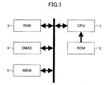
- FIG. 1 is a diagram illustrating an example configuration of an image processing system for reducing binary-format image data according to an embodiment of the present invention.
- This image processing system includes a CPU (Central Processing Unit) 1, a ROM (Read Only Memory) 2, a RAM (Random Access Memory) 3, a DMAC (Direct Memory Access Controller) 4, and an IMEM 5.
- CPU Central Processing Unit
- ROM Read Only Memory
- RAM Random Access Memory
- DMAC Direct Memory Access Controller
- the CPU 1 controls the overall system and performs an operation of reducing the image data, procedures for reducing to be performed according to programs being stored in the ROM 2.
- the RAM 3 is a Random Access Memory for securing a work area required for processing the image data.
- the DMAC (Direct Memory Access Controller) 4 is a DMA controller dedicated for controlling transfer of the image data within the system, while the IMEM 5 is a large-capacity memory for storing the image data.
- this IMEM 5 has stored binary format image data corresponding to at least one page and that, for a reducing process, the image data are transferred to the RAM 3 on a line-by-line basis, the reducing process is performed per runlength on the RAM 3, and reduced data corresponding to one line are produced and again transferred back to the IMEM 5.
- m is a number identifying a runlength, 0 being a fictitious runlength for specifying the initial state.
- BW(m) denotes the logic of the mth runlength, herein specifying 1 for black and 0 for white. Even when this definition of the logic is reversed, implementing the present embodiment is enabled.
- the logic of the first runlength is assumed to be black. There is no impact on the method itself even if the logic of the 1 st runlength is assumed to be white.
- D(m) denotes the logic of the runlength neighboring after reducing, relative to the mth runlength, specifying 1 for black and 0 for white as in the BW(m). Whether the logic of D(m) is made the same as that of BW(m) has no impact on the method itself.
- NL(m) denotes a reduced runlength
- NL'(m) is a provisional runlength for determining NL(m).
- MOD(m) is a remainder (an integer) obtained when computing NL(m).
- a reduction ratio is denoted by x/y (x, y being positive integers with x ⁇ y), and MOD(m) is always smaller than the value of y, representing that MOD(m) is a fraction less than one pixel after reduction.
- This flowchart illustrates a process of reducing corresponding to one line.
- the initial state is set (Step 1).
- D(1) 0 denotes the logic of a neighboring runlength when. a first runlength is reduced, the initial state assumed to be white. Although this does not become a constraint, it is assumed to be white as generally an area outside an effective image area is most often handled as white.
- MOD(0) is set to be 0 for being a remainder obtained by an operation of reducing a fictitious runlength. An operation of reducing is performed for an actual runlength with such initial state.
- a first runlength process is started with m being incremented (Step 2).
- Step 4 whether the value is 0 is determined.
- the provisional values NL'(m) and MOD'(m) become respectively the determined values NL(m) and MOD(m) (Step 5).
- D(m+1) BW(m) (Step 6).
- Step 7 When this condition is fulfilled (Y in Step 7), the determined value NL(m) is set to be one, and MOD(m) is set equal to y subtracted from the provisional value MOD'(m) (Step 8).
- Step 7 and Step 8 This pair of Step 7 and Step 8 is a feature of the present embodiment.
- D(m+1) in the same manner as described above is set equal to BW(m) (Step 6).
- the provisional values NL'(m) and MOD'(m) respectively are assigned as the determined values NL(m) and MOD(m) (Step 9).
- D (m+1) D(m) is substituted as it is (Step 10). This represents that the logic of the runlength neighboring relative to the next runlength does not change as the runlength is lost.
- FIG. 4 illustrates a pixel sequence having a reduction by means of a method of reducing according to the embodiment of the present invention, with stages of its operation illustrated in a table in FIG. 5.
- Step 7 yields "No".
- NL(m) and MOD(m) are respectively substituted with the values of NL'(m) and MOD'(m) as they are.
Landscapes
- Engineering & Computer Science (AREA)
- Multimedia (AREA)
- Signal Processing (AREA)
- Physics & Mathematics (AREA)
- General Physics & Mathematics (AREA)
- Theoretical Computer Science (AREA)
- Image Processing (AREA)
- Editing Of Facsimile Originals (AREA)
- Compression, Expansion, Code Conversion, And Decoders (AREA)
Abstract
Description
- The present invention generally relates to a technology for image processing in a facsimile machine or a copying machine and, more particularly, to an image-processing apparatus for compressing binary-format image data in the facsimile machine or the copying machine.
- Performing a scaling process on data for a binary-format image represented by a facsimile image systematically on a pixel-by-pixel basis depending on a scaling factor causes various inconveniences. More specifically, the inconveniences are pronounced when reducing the data such that performing a thinning-out process on the data systematically in a simple manner may cause a dropout in the image with respect to a fine line, etc., such as a ruled line, a line within a character, and an underline, etc. Thus, the process may cause dropout of the character and difficulty in identifying the character, and loss of the ruled line or the underline. Therefore, various measures have been proposed up to now, especially on a method of reducing.
-
Patent Document 1
JP5-250468A -
Patent Document 2
JP10-341335A -
- In the invention as described in the
Patent Document 1, providing means for converting one pixel of an original image into one pixel of a reduced image when the integer part of the outcome of a multiplication is zero, and means for, when the negative value of the decimal part obtained by converting into the one pixel of the reduced image exceeds a predetermined value, not converting the one pixel of the original image into the reduced image, aims to reduce to the minimum level a crushing or a deformation in reducing an original image such that alternating black and white appears. However, this method is considered to be insufficient, as the original image is limited to a runlength of one pixel, and also from the point of view of keeping a black runlength which is generally an important information item in a binary format image. - Moreover, in the invention as described in the
Patent Document 2, a method is proposed such that image data corresponding to one line for one direction are multiplied by a scaling factor per runlength so as to obtain scaled runlengths, and the decimal part of each of the scaled runlengths is truncated in the ascending order of the magnitude of the decimal part as described above in order to match the number of dots in one line after scaling so as to produce a scaled image, at which time as an exceptional process, the truncating as described above is postponed when the integer part of the scaled runlength is zero; and when even such postponing does not result in a sufficient reducing, the decimal part as described above is eliminated from a white dot. - According to this method, while an occurrence of a runlength (with the integer part of zero) disappearing by reducing may be avoided, final reduced-image data cannot be produced until a runlength-reducing operation for the whole one line has been completed. A buffer memory having a capacity corresponding to one line is required for collating the integer part and the decimal part of each runlength so as to store the collated parts. This may become not only an obstacle when trying to implement a scaling process with a small amount of memory resources, but, also when the process itself is implemented in software by means of a CPU, a burden on the CPU. Thus, in a method of operation for reducing, per runlength, binary format image data corresponding to one line, enabling real-time computing of reduced data with a relatively simple sequential process, and enabling keeping of important information on the image by not causing a loss of a small black runlength, are preferable.
- Accordingly, it is a general object of the present invention to provide a technology for processing images in a facsimile machine or a copying machine that substantially obviates one or more problems caused by the limitations and disadvantages of the related art.
- It is a more particular object of the present invention to provide an apparatus for image processing for compressing binary-format image data in a facsimile machine or a copying machine that enables obtaining a good reduced image with a small amount of pixel dropout.
- According to the invention, in an apparatus for image processing for reducing one or more runlengths by converting binary-format image data for each of black and white runlengths in one direction relative to the data so as to obtain the reduced image data relative to that direction, when performing an operation of the reducing on a given one of the runlengths, the operation of the reducing is performed with reference to one or more runlengths, other than the given runlength, of the same line that have already been administered the operation of the reducing.
- An apparatus for image processing in an embodiment of the invention enables obtaining a good reduced image with a small amount of pixel dropout.
Other objects, features, and advantages of an embodiment of the present invention will become more apparent from the following detailed description when read in conjunction with the accompanying drawings, in which: - FIG. 1 is a block diagram illustrating an example configuration of an image processing system for reducing binary-format image data according to an embodiment of the present invention;
- FIG. 2 is a flowchart illustrating a process according to the embodiment of the present invention;
- FIG. 3 is a schematic diagram for describing conditions for keeping a black pixel lost;
- FIG. 4 illustrates a pixel sequence having administered a reduction by means of a method of reducing according to the embodiment of the present invention; and
- FIG. 5 is a table illustrating an outcome of operation in FIG. 4.
-
- Descriptions are given next, with reference to the accompanying drawings, of a preferred embodiment of the present invention.
- FIG. 1 is a diagram illustrating an example configuration of an image processing system for reducing binary-format image data according to an embodiment of the present invention. This image processing system includes a CPU (Central Processing Unit) 1, a ROM (Read Only Memory) 2, a RAM (Random Access Memory) 3, a DMAC (Direct Memory Access Controller) 4, and an
IMEM 5. - The
CPU 1 controls the overall system and performs an operation of reducing the image data, procedures for reducing to be performed according to programs being stored in theROM 2. TheRAM 3 is a Random Access Memory for securing a work area required for processing the image data. The DMAC (Direct Memory Access Controller) 4 is a DMA controller dedicated for controlling transfer of the image data within the system, while theIMEM 5 is a large-capacity memory for storing the image data. It is assumed that thisIMEM 5 has stored binary format image data corresponding to at least one page and that, for a reducing process, the image data are transferred to theRAM 3 on a line-by-line basis, the reducing process is performed per runlength on theRAM 3, and reduced data corresponding to one line are produced and again transferred back to theIMEM 5. - Repeating this process over the number of lines corresponding to one page completes a process of reducing the image data corresponding to one page. It is to be noted that, while an image-data flow as described above illustrates an example operation of a system to which an embodiment of the present invention is applied, it is possible to implement the present invention with a method other than this method. For example, a procedure such that, image data are transferred from the
IMEM 5 to theRAM 3 per runlength and a reducing process is performed on the image data to form on theRAM 3 reduced-image data corresponding to one line, is possible. - Moreover, while a software method by means of the
CPU 1 is assumed to be an example as other means of implementing, the means of implementing is not limited to such a case. In other words, a method of reducing may be configured in hardware. - Next, a procedure for processing the present embodiment is described with reference to a flowchart in FIG. 2.
- First, letters used herein are described: m is a number identifying a runlength, 0 being a fictitious runlength for specifying the initial state. As a method of reducing according to the present embodiment, the same process is performed for both white and black runlengths, with m incremented by 1, the logic (whether white or black) of the runlengths is switched. BW(m) denotes the logic of the mth runlength, herein specifying 1 for black and 0 for white. Even when this definition of the logic is reversed, implementing the present embodiment is enabled.
- In this flowchart, the logic of the first runlength is assumed to be black. There is no impact on the method itself even if the logic of the 1st runlength is assumed to be white. D(m) denotes the logic of the runlength neighboring after reducing, relative to the mth runlength, specifying 1 for black and 0 for white as in the BW(m). Whether the logic of D(m) is made the same as that of BW(m) has no impact on the method itself.
- It is assumed that the neighboring runlength has already completed a process of reducing, the runlength at or before the (m-1)th being the target for the mth runlength. While D(m) becomes BW(m-1) when the (m-1)th reduced runlength is not zero, when the (m-1)th reduced runlength is zero, D(m) assumes the logic of the runlength at or before the (m-2)th.
- NL(m) denotes a reduced runlength, and NL'(m) is a provisional runlength for determining NL(m). MOD(m) is a remainder (an integer) obtained when computing NL(m). A reduction ratio is denoted by x/y (x, y being positive integers with x < y), and MOD(m) is always smaller than the value of y, representing that MOD(m) is a fraction less than one pixel after reduction.
- This flowchart illustrates a process of reducing corresponding to one line. First, the initial state is set (Step 1). The reduction rate, denoted x/y, may be x=1, y=2 when it is 50%, for example. D(1) = 0 denotes the logic of a neighboring runlength when. a first runlength is reduced, the initial state assumed to be white. Although this does not become a constraint, it is assumed to be white as generally an area outside an effective image area is most often handled as white.
- MOD(0) is set to be 0 for being a remainder obtained by an operation of reducing a fictitious runlength. An operation of reducing is performed for an actual runlength with such initial state. A first runlength process is started with m being incremented (Step 2). The provisional runlength NL'(m) is computed based on Equation (1) (Step 3):
- In this Equation (1), "int" is a process of integerizing by means of truncating the remainder. L(m) is the mth runlength value.
- Next, the provisional remainder MOD'(m) is computed based on Equation (2):
- In this Equation (2), "mod" is a process of computing the remainder.
- Once NL'(m) is computed, whether the value is 0 is determined (Step 4). When NL'(m) is not zero (Y in Step 4), the provisional values NL'(m) and MOD'(m) become respectively the determined values NL(m) and MOD(m) (Step 5). At the same time, it is set that D(m+1) = BW(m) (Step 6).
- On the other hand, when NL'(m) is zero (N in Step 4), whether BW(m)= 1 and D(m) = 0 is determined (Step 7).
- Herein, this physical significance is discussed. BW(m)= 1 represents that the logic of the runlength with an operation of reducing in-progress now is black, while BW(m) = 0 represents that the logic of a runlength neighboring the runlength after the reducing is white. In other words, for a black-pixel sequence whose runlength ends up becoming zero with an operation of reducing, conditions are indicated for extracting one pixel that was to be a change point after reducing (refer to FIG. 3).
- When this condition is fulfilled (Y in Step 7), the determined value NL(m) is set to be one, and MOD(m) is set equal to y subtracted from the provisional value MOD'(m) (Step 8). This pair of
Step 7 andStep 8 is a feature of the present embodiment. - Then, D(m+1) in the same manner as described above is set equal to BW(m) (Step 6). On the other hand, as a result of determining whether BW(m) = 1 and D(m) = 0, when this condition is not fulfilled (N in Step 7), the provisional values NL'(m) and MOD'(m) respectively are assigned as the determined values NL(m) and MOD(m) (Step 9). However, as for D (m+1), D(m) is substituted as it is (Step 10). This represents that the logic of the runlength neighboring relative to the next runlength does not change as the runlength is lost.
- Repeating the process as described above over the runlengths corresponding to one line completes a process of reducing one line.
- Next, an example of performing a reduction according to this process is described.
- FIG. 4 illustrates a pixel sequence having a reduction by means of a method of reducing according to the embodiment of the present invention, with stages of its operation illustrated in a table in FIG. 5. NL' (m) ≠ 0 for the runlength of m = 1 through 4 and the results of determination in
Step 4 in the flowchart in FIG. 2 are all "Y". - When performing an operation of the runlength with m=5, NL' (m) =0, the determination of
step 4 in FIG. 2 becomes "N". At that time, with BW(m) = 1 and D(m) = 0,Step 7 becomes "Y". Therefore, NL(m) is forced to be equal to 1, and with performing the operation MOD(m) = MOD'(m)-y, the result is MOD(m) = -1. - In the runlength with m=6, also with NL' (m) = 0, as BW(m) =0 and D(m) =1,
Step 7 yields "No". In that case, NL(m) and MOD(m) are respectively substituted with the values of NL'(m) and MOD'(m) as they are. - With m=7, in the same manner as NL' (m) =0, as BW(m)=1 and D(m)=1, it will undergo the same process as with m=6.
- Below, with m=9, the same process as that with m=5 is performed, resulting in keeping the black pixel.
- As the value of NL(m) in FIG. 5 becomes the runlength after the reduction, the result is such as the image after reduction as illustrated in FIG. 4.
Claims (4)
- An apparatus for image processing for reducing one or more runlengths by converting binary-format image data for each of black and white runlengths in one direction relative to the data so as to obtain the reduced image data relative to that direction,
characterized in that, when performing the reducing operation on a given one of the runlengths, the reducing operation is performed with reference to one of more runlengths other than the given runlengths of the same line that have already been reduced. - The apparatus for image processing as claimed in claim 1, wherein, when performing the reducing operation on the given runlength, the reducing operation is administered with reference to, out of the other runlengths of the same line that have already been reduced, a runlength which neighbours the given runlength after the reducing operation.
- The apparatus for image processing as claimed in claim 1 or 2, wherein, when an outcome of the operation on a given runlength A is zero, out of the other runlengths of the same fine that have already been reduced, when the logic level of a neighbouring runlength B
after the reducing is the logic level in reverse of the logic level of the runlength A, the outcome of the operation on said runlength A is forced to be one, whereas, when the logic level of the runlength B is the same as the logic level of the runlength A, the outcome is kept as zero. - The apparatus for image processing as claimed in claim 1, 2, or 3, wherein, when the logic level of a given runlength A corresponds to a black pixel and an outcome of the operation is zero, out of the other runlengths of the same line that have already been reduced, when the logic level of a neighbouring runlength B
after the reducing corresponds to a white pixel, the outcome of the operation on said runlength A is forced to be one, whereas, when the logic level of the runlength B corresponds to the black pixel as the logic level of the runlength A, the outcome is kept as zero.
Applications Claiming Priority (2)
| Application Number | Priority Date | Filing Date | Title |
|---|---|---|---|
| JP2003328523 | 2003-09-19 | ||
| JP2003328523A JP2005092757A (en) | 2003-09-19 | 2003-09-19 | Image processing device |
Publications (1)
| Publication Number | Publication Date |
|---|---|
| EP1517268A1 true EP1517268A1 (en) | 2005-03-23 |
Family
ID=34191398
Family Applications (1)
| Application Number | Title | Priority Date | Filing Date |
|---|---|---|---|
| EP04255675A Withdrawn EP1517268A1 (en) | 2003-09-19 | 2004-09-17 | Downscaling of run-length encoded binary images |
Country Status (3)
| Country | Link |
|---|---|
| US (1) | US7508992B2 (en) |
| EP (1) | EP1517268A1 (en) |
| JP (1) | JP2005092757A (en) |
Families Citing this family (3)
| Publication number | Priority date | Publication date | Assignee | Title |
|---|---|---|---|---|
| US7362418B2 (en) | 2004-09-15 | 2008-04-22 | Ricoh Company, Ltd. | Duplicate apparatus |
| JP2008005465A (en) * | 2006-05-23 | 2008-01-10 | Ricoh Co Ltd | Image sensor apparatus, image reading apparatus, and image forming apparatus |
| EP2009895B1 (en) * | 2007-06-29 | 2019-03-06 | Ricoh Company, Ltd. | Image processing apparatus, image reading apparatus, and image processing system |
Citations (4)
| Publication number | Priority date | Publication date | Assignee | Title |
|---|---|---|---|---|
| US4628534A (en) * | 1984-07-06 | 1986-12-09 | Honeywell Information Systems Inc. | Method for changing the resolution of compressed image data |
| EP0552544A1 (en) * | 1991-12-23 | 1993-07-28 | International Business Machines Corporation | An improved method for decoding compressed images |
| JPH05250468A (en) * | 1992-03-05 | 1993-09-28 | Toshiba Corp | Binary image data reduction method |
| JPH10341335A (en) * | 1997-06-10 | 1998-12-22 | Ricoh Co Ltd | Image processor and image-magnifying system |
Family Cites Families (4)
| Publication number | Priority date | Publication date | Assignee | Title |
|---|---|---|---|---|
| US5594815A (en) * | 1992-10-19 | 1997-01-14 | Fast; Bruce B. | OCR image preprocessing method for image enhancement of scanned documents |
| US5867612A (en) * | 1996-03-27 | 1999-02-02 | Xerox Corporation | Method and apparatus for the fast scaling of an image |
| JP4001711B2 (en) | 2000-11-15 | 2007-10-31 | 株式会社リコー | Image reading device |
| JP4008801B2 (en) | 2002-02-21 | 2007-11-14 | 株式会社リコー | Color image reader |
-
2003
- 2003-09-19 JP JP2003328523A patent/JP2005092757A/en active Pending
-
2004
- 2004-09-14 US US10/940,336 patent/US7508992B2/en not_active Expired - Fee Related
- 2004-09-17 EP EP04255675A patent/EP1517268A1/en not_active Withdrawn
Patent Citations (4)
| Publication number | Priority date | Publication date | Assignee | Title |
|---|---|---|---|---|
| US4628534A (en) * | 1984-07-06 | 1986-12-09 | Honeywell Information Systems Inc. | Method for changing the resolution of compressed image data |
| EP0552544A1 (en) * | 1991-12-23 | 1993-07-28 | International Business Machines Corporation | An improved method for decoding compressed images |
| JPH05250468A (en) * | 1992-03-05 | 1993-09-28 | Toshiba Corp | Binary image data reduction method |
| JPH10341335A (en) * | 1997-06-10 | 1998-12-22 | Ricoh Co Ltd | Image processor and image-magnifying system |
Non-Patent Citations (2)
| Title |
|---|
| PATENT ABSTRACTS OF JAPAN vol. 0180, no. 14 (P - 1672) 11 January 1994 (1994-01-11) * |
| PATENT ABSTRACTS OF JAPAN vol. 1999, no. 03 31 March 1999 (1999-03-31) * |
Also Published As
| Publication number | Publication date |
|---|---|
| JP2005092757A (en) | 2005-04-07 |
| US7508992B2 (en) | 2009-03-24 |
| US20050084170A1 (en) | 2005-04-21 |
Similar Documents
| Publication | Publication Date | Title |
|---|---|---|
| JP3486433B2 (en) | Page printer with automatic font compression | |
| US8169656B2 (en) | Image processing devices and methods for resizing an original image therefor | |
| US6683997B1 (en) | Apparatus and method for resolution transformation of orthogonal transformation image | |
| CN106488074A (en) | Image processing apparatus and e-file generation method | |
| EP1517268A1 (en) | Downscaling of run-length encoded binary images | |
| JP3062382B2 (en) | Image processing apparatus and method | |
| EP0870276B1 (en) | A method for transforming a gray-level image into a black-and-white image | |
| JP2002077612A (en) | Image processing method and image processing apparatus | |
| JP4260908B2 (en) | Run-length encoding method and image processing apparatus | |
| JPH07221976A (en) | Smoothing enlargement processing method for binary image data | |
| JP2770775B2 (en) | Drawing apparatus and drawing method | |
| JPH10341335A (en) | Image processor and image-magnifying system | |
| JPH0690363A (en) | Predictive coding system coding device and decoding device | |
| JPH0385962A (en) | Picture size reduction device in facsimile equipment | |
| JP3344115B2 (en) | Image processing device | |
| JPS63107269A (en) | Image processing system | |
| JPH09238253A (en) | Image processing apparatus and method | |
| JP4469511B2 (en) | Image processing method | |
| JP2001126029A (en) | Image processing method, apparatus and recording medium | |
| JP2001223897A (en) | Image processing device | |
| JPH08149284A (en) | Image forming device | |
| JPH08125874A (en) | Output device for compressing and holding data and data compression control method | |
| JP2002290734A (en) | Image processing method | |
| JPH06164899A (en) | Facsimile equipment | |
| JPH089148A (en) | Image forming device |
Legal Events
| Date | Code | Title | Description |
|---|---|---|---|
| PUAI | Public reference made under article 153(3) epc to a published international application that has entered the european phase |
Free format text: ORIGINAL CODE: 0009012 |
|
| 17P | Request for examination filed |
Effective date: 20040925 |
|
| AK | Designated contracting states |
Kind code of ref document: A1 Designated state(s): AT BE BG CH CY CZ DE DK EE ES FI FR GB GR HU IE IT LI LU MC NL PL PT RO SE SI SK TR |
|
| AX | Request for extension of the european patent |
Extension state: AL HR LT LV MK |
|
| AKX | Designation fees paid |
Designated state(s): DE ES FR GB IT NL |
|
| 17Q | First examination report despatched |
Effective date: 20070801 |
|
| STAA | Information on the status of an ep patent application or granted ep patent |
Free format text: STATUS: THE APPLICATION IS DEEMED TO BE WITHDRAWN |
|
| 18D | Application deemed to be withdrawn |
Effective date: 20130403 |