BACKGROUND OF THE INVENTION
1. Field of the Invention
-
The present invention relates in general to automotive
power transmissions and more particularly to the automotive
power transmissions of a type that is equipped with a
synchromesh mechanism. More specifically, the present
invention is concerned with an improvement in the synchromesh
mechanism employed in the automotive power transmission.
2. Description of the Related Art
-
Japanese Laid-open Patent Application (Tokkaihei) 6-33952
and Japanese Laid-open Utility Model Application
(Jikkaihei) 6-8824 show an automotive power transmission
equipped with a synchromesh mechanism (or synchronizer). The
power transmission comprises generally a coupling sleeve, a
synchronizing hub, a balk ring and a clutch gear which are
coaxially arranged. That is, when, upon movement of a shift
lever by a driver, the coupling sleeve is axially moved toward the
balk ring, chamfered edges of these elements are brought into
contact with each other thereby stopping movement of the
coupling sleeve. During the axial movement of the coupling
sleeve, a cone surface of the balk ring is brought into contact
with a cone surface of the clutch gear thereby to produce a
friction torque (viz., synchronizing force) inducing rotation of the
balk ring and synchronizing hub at the same speed.
SUMMARY OF THE INVENTION
-
In the synchromesh mechanism of the above-mentioned
type, the friction torque (viz., synchronizing force) produced upon
intimate contact of the balk ring cone surface with the clutch gear
cone surface is entirely and directly transmitted to the coupling
sleeve and thus to the shift lever. This direct transmission of the
friction torque to the shift lever inevitably increases the force
against which the driver has to manipulate the shift lever for a
gear change. Furthermore, in a semi-automatic power
transmission wherein movement of the coupling sleeve for the
gear change is carried out by an electric power with a clutch kept
disengaged, a high power electric actuator has to be used, which
however brings about a bulky and highly-cost construction of the
transmission.
-
It is therefore an object of the present invention to provide
an automotive power transmission with a synchromesh
mechanism, which is free of the above-mentioned drawbacks.
-
According to the present invention, there is provided an
automotive power transmission with a synchromesh mechanism,
which can effectively reduce a peak value of an operation load
needed for moving the coupling sleeve to achieve a gear change.
-
According to the present invention, there is provided, in an
automotive power transmission, a synchronizing support force
generating mechanism that induces a relative rotation between a
synchronizing hub and a balk ring when, upon shifting of a
coupling sleeve toward the balk ring, a balk ring cone surface and
a clutch gear cone surface frictionally contact to produce a friction
torque, and converts a circumferential force produced as a result
of the relative rotation between the synchronizing hub and the
balk ring to an axially applied synchronizing support force with
which the balk ring is pressed against the clutch gear.
-
In accordance with a first aspect of the present invention,
there is provided an automotive power transmission with a
synchromesh mechanism, which comprises a transmission
rotation shaft; a synchronizing hub coaxially disposed about the
transmission rotation shaft through a spline connection, thereby
rotate therewith about an axis of the transmission rotation shaft;
a coupling sleeve coaxially disposed about the synchronizing hub
through a spline connection, thereby rotate therewith about the
axis of the transmission rotation shaft; a speed gear rotatably
disposed about the transmission rotation shaft; a clutch gear
tightly and coaxially disposed on the speed gear to rotate
therewith, clutch gear having a clutch gear cone surface; a balk
ring arranged between the clutch gear and the coupling sleeve,
the balk ring having a balk ring cone surface that is intimately
contactable with the clutch gear cone surface, the balk ring
having key grooves; insert keys held by the coupling sleeve to
move therewith, each insert key having one end that is engaged
with one of the key grooves of the balk ring to induce an integral
rotation of the coupling sleeve with the balk ring when the
coupling sleeve is axially shifted toward the balk ring; and
a synchronizing support force generating mechanism that induces
a relative rotation between the synchronizing hub and the balk
ring when, upon shifting of the coupling sleeve toward the balk
ring, the balk ring cone surface is brought into frictional contact
with the clutch gear cone surface to produce a friction torque
therebetween, and converts a circumferential force produced as a
result of the relative rotation between the synchronizing hub and
the balk ring to an axially applied synchronizing support force
with which the balk ring is pressed against the clutch gear.
-
In accordance with a second aspect of the present invention,
there is provided an automotive power transmission with a
synchromesh mechanism, which comprises a transmission
rotation shaft; a synchronizing hub coaxially disposed about the
transmission rotation shaft through a spline connection, thereby
rotate therewith about an axis of the transmission rotation shaft;
a coupling sleeve coaxially disposed about the synchronizing hub
through a spline connection, thereby rotate therewith about the
axis of the transmission rotation shaft; a speed gear rotatably
disposed about the transmission rotation shaft; a clutch gear
tightly and coaxially disposed on the speed gear to rotate
therewith, clutch gear having a clutch gear cone surface; a balk
ring arranged between the clutch gear and the coupling sleeve,
the balk ring having a balk ring cone surface that is intimately
contactable with the clutch gear cone surface, the balk ring
having key grooves; insert keys held by the coupling sleeve to
move therewith, each insert key having one end that is engaged
with one of the key grooves of the balk ring to induce an integral
rotation of the coupling sleeve with the balk ring when the
coupling sleeve is axially shifted toward the balk ring; a
synchronizing support force generating mechanism that induces a
relative rotation between the synchronizing hub and the balk
ring when, upon shifting of the coupling sleeve toward the balk
ring, the balk ring cone surface is brought into frictional contact
with the clutch gear cone surface to produce a friction torque
therebetween, and converts a circumferential force produced as a
result of the relative rotation between the synchronizing hub and
the balk ring to an axially applied synchronizing support force
with which the balk ring is pressed against the clutch gear and a
return mechanism that forces the balk ring to return to a rest
position separating the balk ring cone surface from the clutch
gear cone surface when the coupling sleeve is returned to its
neutral position or spline teeth of the coupling sleeve are fully
engaged with spline teeth of the clutch gear.
BRIEF DESCRIPTION OF THE DRAWINGS
-
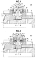
- Fig. 1 is a sectional view of a synchromesh mechanism
employed in a first embodiment of the present invention, at a
part where an insert key is shown;
- Fig. 2 is a view similar to Fig. 1, but showing a part where a
return key is shown;
- Fig. 3A is a side view of a first balk ring employed in the
synchromesh mechanism in the first embodiment;
- Fig. 3B is a front view of the first balk ring of Fig. 3A;
- Fig. 4A is a side view of a synchronizing hub employed in
the synchromesh mechanism in the first embodiment;
- Fig. 4B is a front view of the synchronizing hub of Fig. 4A;
- Fig. 5A is a perspective view of a synchronizing support
force generating mechanism employed in the synchromesh
mechanism in the first embodiment, at a part where the first balk
ring is arranged;
- Fig. 5B is a perspective of the synchronizing support force
generating mechanism at a part where the synchronizing hub is
arranged;
- Fig. 5C is a perspective view of a return mechanism
employed in the first embodiment, at a part where a second balk
ring is arranged;
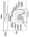
- Fig. 6 is a time chart depicting the characteristics of
operation load needed by a coupling sleeve for achieving a gear
change, in case of the first embodiment of the present invention;
- Figs. 7A and 7B are schematic illustrations depicting a
mechanism for generating a synchronizing support force in case
of the first embodiment;
- Fig. 8 is a sectional view of a synchromesh mechanism
employed in a second embodiment of the present invention, at a
part where an insert key is shown;
- Fig. 9 is a view similar to Fig. 8, but showing a part where a
return key is shown;
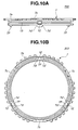
- Fig. 10A is a side view of a first balk ring employed in the
synchromesh mechanism in the second embodiment;
- Fig. 10B is a front view of the first balk ring of Fig. 10A;
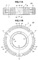
- Fig. 11A is a side view of a synchronizing hub employed in
the synchromesh mechanism in the second embodiment;
- Fig. 11B is a front view of the synchronizing hub of Fig.
11A;
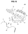
- Fig. 12 is a perspective partial view of an essential portion
of the synchromesh mechanism of the second embodiment;
- Figs. 13A and 13B are schematic illustrations depicting a
mechanism for generating a synchronizing support force in case
of the second embodiment;
- Fig. 14 is a sectional view of a synchromesh mechanism
employed in a third embodiment of the present invention, at a
part where a synchronizing support force generating mechanism
is arranged;
- Figs. 15A and 15B are side views of the synchromesh
mechanism employed in the third embodiment, showing different
operation conditions of the mechanism respectively;
- Fig. 16 is an exploded perspective partial view of a
synchronizing support force generating mechanism employed in
the third embodiment;
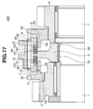
- Fig. 17 is a sectional view of a synchromesh mechanism
employed in a fourth embodiment of the present invention, at a
part where a synchronizing support force generating mechanism
is arranged;
- Figs. 18A and 18B are side views of the synchromesh
mechanism employed in the fourth embodiment, showing
different operation conditions of the mechanism respectively;
- Fig. 19 is an exploded perspective partial view of the
synchronizing support force generating mechanism employed in
the fourth embodiment;
- Fig. 20 is a view similar to Fig. 19, but showing a
modification of the synchronizing support force generating
mechanism employed in the fourth embodiment;
- Fig. 21 is a sectional view of a synchromesh mechanism
employed in a fifth embodiment of the present invention, at a
part where a return mechanism is arranged;
- Fig. 22A is a side view of a first balk ring employed in the
synchromesh mechanism in the fifth embodiment;
- Fig. 22B is a front view of the first balk ring of Fig. 22A;
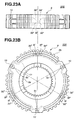
- Fig. 23A is a side view of a synchronizing hub employed in
the synchromesh mechanism in the fifth embodiment;
- Fig. 23B is a front view of the synchronizing hub of Fig.
23A;
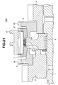
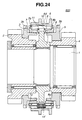
- Fig. 24 is a sectional view of a synchromesh mechanism
employed in a sixth embodiment of the present invention, at a
part where a return mechanism is arranged;
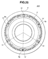
- Fig. 25 is a front view of a synchronizing hub and a
coupling sleeve that are incorporated with the return mechanism
in the sixth embodiment;
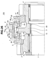
- Fig. 26 is a sectional view of a synchromesh mechanism
employed in a seventh embodiment of the present invention, at a
part where a synchronizing support force generating mechanism
is arranged;
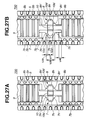
- Figs. 27A and 27B are side views of the synchromesh
mechanism employed in the seventh embodiment, showing
different operation conditions of the mechanism respectively;
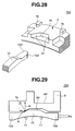
- Fig. 28 is an exploded perspective partial view of the
synchronizing support force generating mechanism employed in
the seventh embodiment;
- Fig. 29 is an illustration depicting a counterforce of the
synchronizing support force, that is partially received by a
coupling sleeve, in case of the seventh embodiment; and
- Fig. 30 is a time chart depicting the characteristics of
operation load needed by a coupling sleeve for achieving a gear
change, in case of the seventh embodiment of the present
invention.
-
DETAILED DESCRIPTION OF THE EMBODIMENTS
-
In the following, the present invention will be described in
detail with reference to seven embodiments 100, 200, 300, 400,
500, 600 and 700 with the aid of the accompanying drawings.
-
For ease of understanding, various directional terms, such
as, right, left, upper, lower, rightward and the like are used in the
description. However, such terms are to be understood with
respect to only a drawing or drawings on which corresponding
part or portion is shown.
-
Furthermore, throughout the description, substantially the
same parts are denoted by the same numerals, and repeated
explanation on such same parts will be omitted for simplification
of the description.
-
Referring to Figs. 1 to 7, particularly Figs. 1 and 2, there is
shown a synchromesh mechanism 100 employed in a first
embodiment of the present invention.
-
As shown in the drawings, particularly Figs. 1 and 2,
synchromesh mechanism 100 generally comprises a transmission
rotation shaft 1, a first gear 2, a first clutch gear 3, a second gear
4, a second clutch gear 5, a coupling sleeve 6, a first balk ring 7,
a second balk ring 8, a synchronizing hub 9 and three insert keys
10.
-
On axially spaced two portions of transmission rotation
shaft 1, there are rotatably disposed first gear 2 and second gear
4 respectively. First clutch gear 3 is press-fitted to first gear 2 to
constitute a single unit, and similar to this, second clutch gear 5
is press-fitted to the second gear 4 to constitute a single unit. As
shown, first clutch gear 3 and second clutch gear 5 are arranged
to face each other with a certain space kept therebetween. First
and second clutch gears 3 and 5 are respectively formed with
cone surfaces 3a and 5a which are identical in shape. Each
clutch gear 3 or 5 is formed with a plurality of spline teeth 3b or
5b.
-
Coupling sleeve 6 is arranged between first gear 2 and
second gear 4 to serve as an input member through which a
speed change operation load is inputted to gear 2 or 4. Coupling
sleeve 6 is connected with synchronizing hub 9 by means of a
spline connection, and thus, these two elements 6 and 9 rotate
like a single unit while permitting an axial movement of coupling
sleeve 6 relative to synchronizing hub 9.
-
On a cylindrical inner surface of coupling sleeve 6, there are
formed three equally spaced key grooves 6a for supporting
respective insert keys 10 (see Fig. 4B) and axially spaced left and
right spline teeth 6c and 6c each having an axially outer end 6b
chamfered. Coupling sleeve 6 is formed therearound with a fork
groove 6d with which forks of a shift fork (not shown) are
operatively engaged.
-
First balk ring 7 is an axially movable synchronizing
member that smoothly synchronizes rotation of first gear 2 with
that of synchronizing hub 9.
-
As will be clarified from the following, first balk ring 7 is
permitted to make a rotation of a predetermined angle about the
axis of transmission rotation shaft 1 relative to synchronizing hub
9 under a given condition. When, due to the rotation of first balk
ring 7 relative to synchronizing hub 9, an inclined part of first
balk ring 7 and an inclined part of synchronizing hub 9 are
brought into an intimate contact, a so-called synchronizing
support force "Fa" is produced with which first balk ring 7 is
pressed against first clutch gear 3.
-
That is, on a cylindrical inner surface of first balk ring 7,
there is formed a first balk ring cone surface 7a that is intimately
contactable with the above-mentioned first clutch gear cone
surface 3a, and on an outer surface of first balk ring 7, there is
formed a first chamfer 7b.
-
Furthermore, as is seen from Fig. 3B, first balk ring 7 is
formed with three equally spaced key grooves 7c each of which is
shaped and sized to receive one end part of the corresponding
insert key 10. Each key groove 7c is defined between opposed
banks 7c, as is clearly shown in Fig. 5A.
-
Referring back to Figs. 1 and 2, second balk ring 8 is an
axially movable synchronizing member that smoothly
synchronizes rotation of second gear 4 with that of synchronizing
hub 9. Furthermore, second balk ring 8 is permitted to make a
rotation of predetermined angle relative to synchronizing hub 9.
That is, like the above-mentioned first balk ring 7, second balk
ring 8 is permitted to make a rotation about the axis of
transmission rotation shaft 1 by a predetermined angle relative to
synchronizing hub 9. Furthermore, like first balk ring 7, second
balk ring 8 is formed with three equally spaced key grooves (not
shown) each of which is shaped and sized to receive the other
end part of the corresponding insert key 10.
-
On a cylindrical inner surface of second balk ring 8, there is
formed a second balk ring cone surface 8a that is intimately
contactable with the above-mentioned second clutch gear cone
surface 5a, and on an outer surface of second balk ring 8, there
is formed a second chamfer 8b.
-
Synchronizing hub 9 is a synchronizing member that is
arranged between the above-mentioned two balk rings 7 and 9,
and is connected to transmission rotation shaft 1 through a spline
connection. On a cylindrical inner surface of synchronizing hub 9,
there are formed a plurality of spline teeth 9a (see Fig. 2) that
are operatively engaged with spline teeth 1a formed on
transmission rotation shaft 1. While, on a cylindrical outer
surface of synchronizing hub 9, there are formed a plurality of
spline teeth 9b that are operatively engaged with spline teeth 6b
of the above-mentioned coupling sleeve 6.
-
As is seen from Fig. 4B, three insert keys 10 are axially
movably received in respective key grooves 9c that are formed at
equally spaced three positions of the outer surface of
synchronizing hub 9. As is seen from Fig. 5B, each key groove 9c
is defined between leading ends of circumferentially extending
two narrow banks 9x and 9x of synchronizing hub 9. As is seen
from this drawing, due to provision of such two banks 9x and 9x,
first and second bay portions 9y and 9y' are defined by
synchronizing hub 9 at left and right sides of two banks 9x and
9x, respectively.
-
The three insert keys 10 are supported by synchronizing
hub 9, coupling sleeve 6 and a semi-circular key spring 11. Each
insert key 10 has at its outer surface a key projection that is
locked in the corresponding key groove 6a of coupling sleeve 6 to
achieve positioning of insert key 10. Thus, insert keys 10 can
rotate together with synchronizing hub 9 and can axially move
together with coupling sleeve 6.
-
In the following, a synchronizing support force generating
mechanism and a return mechanism that constitute an essential
part of synchromesh mechanism 100 of the present invention will
be described with reference to the drawings.
-
For such description, Figs. 3A, 3B, 4A, 4B, 5A, 5B and 5C
will be used in addition to the above-mentioned Figs. 1 and 2.
Figs. 3A and 3B show first balk ring 7, Figs. 4A and 4B show
synchronizing hub 9 and Figs. 5A, 5B and 5C are drawings
depicting the construction of the synchronizing support force
generating mechanism.
-
As will become apparent as the description proceeds, the
synchronizing support force generating mechanism includes a
first arrangement having a function wherein before coupling
sleeve 6 presses first balk ring cone surface 7a upon contact
between chamfer 6b of coupling sleeve 6 and chamfer 7b of first
balk ring 7, there is produced a synchronizing support force that
presses first balk ring cone surface 7a, and a second
arrangement having a function wherein before coupling sleeve 6
presses second balk ring cone surface 8a upon contact between
chamfer 6b of coupling sleeve 6 and chamfer 8b of second balk
ring 8, there is produced a synchronizing support force that
presses second balk ring cone surface 8a.
-
The first arrangement of the synchronizing support force
generating mechanism comprises, as is seen from Fig. 5A, a pair
of inclined surfaces 7d and 7d provided at both sides of each key
groove 7c of first balk ring 7, and, as is seen from Fig. 5B, a pair
of inclined surfaces 9d and 9d provided at both sides of each key
groove 9c of synchronizing hub 9. More specifically, the paired
inclined surfaces 7d and 7d are provided on outer walls of
circumferentially spaced two banks 7x and 7x of first balk ring 7.
As will become apparent, the paired inclined surfaces 7d and 7d
of first balk ring 7 are intimately contactable with the paired
inclined surfaces 9d and 9d of synchronizing hub 9.
-
Like the first arrangement, the second arrangement of the
synchronizing support force generating mechanism comprises a
pair of inclined surfaces (not shown) provided at both sides of
each key groove (not shown) of second balk ring 8, and a pair of
inclined surfaces 9d' and 9d' (see Fig. 5B) provided at both sides
of each key groove 9c of synchronizing hub 9. The paired
inclined surfaces of second balk ring 8 are intimately contactable
with the paired inclined surfaces 9d' and 9d' of synchronizing hub
9.
-
Preferably, for achieving an appropriate synchronizing
support force "Fa", each inclined surface 7d, 9d or 9d' has an
inclination angle of about 45 degrees relative to an imaginary
plane that is perpendicular to an axis of transmission rotation
shaft 1.
-
As is seen from Figs. 5A and 5B, a length "L1" between the
outer walls of banks 7x and 7x of first balk ring 7 is smaller than
a width "L2" of first bay portion 9y of synchronizing hub 9. That
is, the following inequality is established:
L1 < L2
-
As will become apparent as the description proceeds, the
return mechanism includes a first arrangement having a function
wherein when coupling sleeve 6 is in its neutral position or when
coupling sleeve 6 is completely meshed with first clutch gear 3,
first balk ring 7 is returned to its original position to suppress
generation of the synchronizing support force while separating
first balk ring cone surface 7a from first clutch gear cone surface
3a, and a second arrangement having a function wherein when
coupling sleeve 6 is in its neutral position or when coupling sleeve
6 is completely meshed with second clutch gear 5, second balk
ring 8 is returned to its original position to suppress generation of
the synchronizing support force while separating second balk ring
cone surface 8a from second clutch gear cone surface 5a.
-
As is understood from Figs. 2, 3 and Fig. 5C, each of the
first and second arrangements of the return mechanism
comprises an annular recess 9e (see Fig. 2) formed on
synchronizing hub 9 and having an inclined bottom surface, three
equally spaced return keys 12 engageable with annular recess 9e,
an annular spring 13 biasing the return keys 12 radially outward
toward the annular recess 9e and an annular spring groove 7e or
8e formed on first balk ring 7 or second balk ring 8 for receiving
annular spring 13.
-
In the following, operation of synchromesh mechanism 100
of the first embodiment will be described with reference to the
drawings, particularly Figs. 1, 6, 7A and 7B.
SYNCHRONIZING OPERATION
-
First, synchronizing operation effected when, for achieving
a shift-up operation, coupling sleeve 6 is shifted leftward in Fig. 1
will be described. Upon such shifting, higher speed rotation of
first gear 2 would be reduced to be synchronized with lower
speed rotation of transmission rotation shaft 1.
-
As is seen from the time chart of Fig. 6, when a shift lever
(not shown) is shifted at time "t0", coupling sleeve 6 in the
neutral position as shown in Fig. 1 is moved leftward together
with the three insert keys 10. As shown in the time chart, just
after time "t0", operating load is gradually increased, and at time
"t1", a detent feeling member (not shown) incorporated with the
shift lever rides over detent balls against a biasing force of a
spring (not shown). Thus, at time "t1", a so-called "shift check
load" shows its peak. Thereafter, the load lowers to time "t2"
when insert keys 10 start to intimately contact first balk ring 7.
Thus, as is seen from the time chart, a so-called "insert key load"
starts to increase. When, due to increase of the insert key load,
first balk ring 7 is moved leftward in Fig. 1, first balk ring cone
surface 7a is brought into intimate contact with first clutch gear
cone surface 3a to generate a friction torque. Thus, at time "t3",
the synchronizing operation induced by the synchronizing support
force starts.
-
Upon starting of the synchronizing operation, the friction
torque between the two cone surfaces 7a and 3a brings about a
slight relative rotation between first balk ring 7 and synchronizing
hub 9 inducing a condition wherein each insert key 10 is in
contact with one of circumferential side walls of one of the three
key grooves 7c of first balk ring 7.
-
Upon this, as is seen from Fig. 7B, one inclined surface 7d
of first balk ring 7 is in contact with corresponding inclined
surface 9d of synchronizing hub 9, and thus, as is seen from this
drawing, a relative rotation force "F" is produced which is
perpendicularly applied to inclined surface 7d of first balk ring 7.
As shown, the force "F" includes an axial component force "Fa"
and a circumferential component force "Fb".
-
It is to be noted that the axial component force "Fa" is a
synchronizing support force with which first balk ring 7 is biased
toward first gear 2.
-
Referring back to the time chart of Fig. 6, the axial
component force "Fa" shows a peaked characteristic in a range
from time "t3" to time "t5". That is, at time "t4", the axial
component force "Fa" shows a peak, and at time "t5", a switching
takes place as will be described in the following.
-
Due to work of the axial component force "Fa", a friction
force is produced between first clutch gear cone surface 3a and
first balk ring cone surface 7a, and a relative rotation speed "ΔN"
between transmission rotation shaft 1 (viz., synchronizing hub 9)
and first gear 2 (viz., first clutch gear 3) reduces from an initial
value "ΔN1" to a value "ΔN0". This synchronization is carried out
between synchronizing hub 9 and first balk ring 7, and a
counterforce of the synchronizing support force "Fa" is received
by synchronizing hub 9 connected to transmission rotation shaft 1,
and thus, it never occurs that the counterforce of the
synchronizing support force "Fa" is transmitted to coupling sleeve
6. That is, the synchronizing support force "Fa" that is
mechanically produced functions to support the shift operation
without increasing the load needed for carrying out the shifting
movement.
-
With passage of time, coupling sleeve 6 is further moved,
and at time "t5" of the time chart of Fig. 6, the synchronizing
support force "Fa" is matched with the load applied to coupling
sleeve 6. Upon this, the chamfered end 6b of coupling sleeve 6
becomes in contact with first chamfer 7b of first balk ring 7 and
thus, the further movement of coupling sleeve 6 is suppressed.
Upon this, there is produced a certain friction torque between
first clutch gear cone surface 3a and first balk ring cone surface
7a, and thus, a synchronization under a balked condition takes
place therebetween in a conventional manner.
-
As is understood from the time chart of Fig. 6, this
synchronizing operation effected by the contact between
chamfered end 6b and first chamfer 7b needs only a reduction in
the relative rotation speed "ΔN" from the value "ΔN0" that has
been previously reduced by the mechanical synchronizing
operation to 0 (zero), and thus, the operation load at time "t6" is
low, and at time "t7" when the relative rotation speed "ΔN"
becomes 0 (zero), the synchronization operation is finished or
completed.
-
Upon this complement, the friction torque disappears and
thus, the force for stopping coupling sleeve 6 disappears thereby
permitting movement of the same. In response to the axial
movement of coupling sleeve 6 after time "t6", each insert key 10
is disengaged from the corresponding key groove 6a of coupling
sleeve 6, and at time "t7", the insert key 10 pushes away first
balk ring 7, and then at time "t8", coupling sleeve 6 becomes
fully engaged with spline teeth of first clutch gear 3, and then at
time "t9", the shift operation is finished.
-
As is seen from the time chart of Fig. 6, in a conventional
synchromesh mechanism, during the synchronizing operation,
chamfered portions of coupling sleeve and balk ring contact, and
in case wherein for achieving the synchronizing operation, the
reduction of relative rotation speed "ΔN" from the initial value
"ΔN1" to zero is achieved by only the operation load applied from
the coupling sleeve, the operation load is rapidly increased at a
time just before the time "t4" and at a time near the time "t6",
the operation load is lowered.
-
While in synchromesh mechanism 100 of the first
embodiment of the present invention, the synchronizing support
force for reducing the relative rotation speed "ΔN" from the initial
value "ΔN1" to the value "ΔN0" is previously compensated by the
synchronizing support force "Fa" generated by the contact
between inclined surfaces 7d and 9d before the contact between
chamfered end 6b of coupling sleeve 6 and first chamfer 7b of
first balk ring 7. Thus, as is seen from the time chart of Fig. 6, a
lower operation load characteristic is obtained in the range from
time "t5" to time "t7". Actually, the hatched area shown in the
time chart of Fig. 6 depicts an amount by which the operation
load is reduced in the present invention as compared with the
conventional synchromesh mechanism.
-
Accordingly, according to the first embodiment 100 of the
present invention, manipulation of the shift lever by the driver is
easily carried out with a reduced operating force. Furthermore,
in case of the semi-automatic power transmission, it is only
necessary to prepare a relatively low power electric actuator for
assisting movement of coupling sleeve.
RETURN OPERATION OF BALK RING
-
As is described hereinabove, in the synchromesh
mechanism 100 of the first embodiment, the shift-up operation is
easily carried out with a reduced operating force applied to the
shift lever.
-
Upon completion of the synchronization, each return key 12
is slid up in the annular recess 9e of synchronizing hub 9 due to
the biasing force of annular spring 13. As a result, first balk ring
7 is returned toward synchronizing hub 9, and thus, first balk ring
cone surface 7a is separated from first clutch gear cone surface
3a thereby producing no friction force therebetween any longer.
Thus, a shift-down operation effected against such friction force is
easily carried out with a reduced operation force.
-
The need of such separation of first balk ring cone surface
7a from first clutch gear cone surface 3a will become apparent
from the following description.
-
As is described hereinabove, first and second balk rings 7
and 8 are rotatable relative to synchronizing hub 9 and axially
movable relative to the same. Thus, if a specified measure
according to the first embodiment 100 of the invention is not
employed, the following undesired phenomena tend to occur.
-
That is, in the synchronizing support force generating
mechanism that is not selected, a lubrication oil put between balk
ring cone surface 7a or 8a and clutch gear cone surface 3a or 5a
brings about a relative rotation between synchronizing hub 9 and
balk ring cone surface 7a or 8a due to viscosity of the lubrication
oil. Under this condition, the synchronizing support force
generating mechanism is forced to operate even when coupling
sleeve 6 is not applied with a shifting force, and thus, cone
surface 7a or 8a and cone surface 3a or 5a are worn down
shortening the life of synchromesh mechanism. In worst case,
due to the synchronizing support force generated, the relative
rotation between synchronizing hub 9 and balk ring 7 or 8
becomes zero which may cause a locked condition of the
transmission. This will be called first drawback.
-
Furthermore, in the synchronizing support force generating
mechanism that is selected, when, after completion of the
synchronization, the spline teeth of coupling sleeve 6 and those
of clutch gear 3 or 5 keep their engagement, there is produced
no force that presses balk ring 7 or 8 and thus balk ring cone
surface 7a or 8a is kept separated from clutch gear cone surface
3a or 5a. However, due to a fluctuation in engine speed, it tends
to produce a relative rotation between synchronizing hub 9 and
balk ring 7 or 8. If such relative rotation becomes marked, the
synchronizing support force generating mechanism becomes
operative. In this case, the balk ring 7 or 8 is pressed against
clutch gear 3 or 5 inducing an engaged condition between balk
ring cone surface 7a or 8a and clutch gear cone surface 3a or 5a.
If this engaging condition is kept, a speed change operation from
an existing speed to another speed needs a certain force for
disengaging the two cone surfaces 7a (or 8a) and 3a (or 5a),
which increases the force applied to coupling sleeve 6. This will
be called second drawback.
-
However, the first embodiment 100 of the present invention
is free of the above-mentioned undesired phenomena because of
provision of the return mechanism.
-
That is, due to work of such return mechanism, when
coupling sleeve 6 returns to the neutral position, first balk ring 7
or second balk ring 8 is returned to its original position
disengaging balk ring cone surface 7a or 8a from clutch gear
cone surface 3a or 5a. With this, the above-mentioned first
drawback is suppressed.
-
Furthermore, due to work of the return mechanism, when
the spline teeth of coupling sleeve 6 and those of first clutch gear
3 (or second clutch gear 5) are kept engaged, first balk ring 7 or
second balk ring 8 is returned to its original position disengaging
balk ring cone surface 7a or 8a from clutch gear cone surface 3a
or 5a. With this, the above-mentioned second drawback is
suppressed.
-
In the following, various advantages obtained in the
synchromesh mechanism 100 of the first embodiment of the
present invention will be described.
- (1) Due to provision of the synchronizing support force
generating mechanism, the peak value of operation load needed
for achieving the synchronization can be lowered. That is,
because of the friction torque generated between balk ring cone
surface 7a or 8a and clutch gear cone surface 3a or 5a during the
speed change operation, the circumferential force "F" produced
due to the relative rotation between synchronizing hub 9 and balk
ring 7 or 8 can be converted to the axial component force "Fa"
that presses balk ring 7 or 8 against clutch gear 3 or 5. Thus,
the peak value of operation load needed for achieving the
synchronization can be considerably lowered. Thus, in case of
manual transmissions, the force needed by the driver for
actuating the shift lever can be reduced, and furthermore, in case
of a semi-automatic power transmissions, a relatively low power
electric actuator can be used for assisting movement of coupling
sleeve.
- (2) Due to provision of the return mechanism, the
synchronizing support force is not generated when coupling
sleeve 6 is in its neutral position and coupling sleeve 6 and clutch
gear 3 or 5 are fully engaged at their spline teeth. That is, due to
provision of the return mechanism, balk ring cone surface 7a or
8a is disengaged from clutch gear cone surface 3a or 5a under
such condition. Accordingly, a clearance between balk ring cone
surface 7a or 8a and clutch gear cone surface 3a or 5a, that is
not operative in carrying out the speed change, is assuredly
provided, which prevents such cone surfaces from having marked
wearing. Furthermore, due to provision of the return mechanism,
engagement between balk ring cone surface 7a or 8a and clutch
gear cone surface 3a or 5a after completion of the speed change
to a desired speed is suppressed.
- (3) As is seen from Figs. 5A and 5B, due to provision of
inclined surfaces 7d and 7d of bulk ring 7 (or 8) and inclined
surfaces 9d and 9d of synchronizing hub 9, the relative rotation
between bulk ring 7 (or 8) and synchronizing hub 9 induces an
intimate contact between the inclined surfaces 7d and 7d and the
inclined surfaces 9d and 9d, which produces the synchronizing
support force "Fa". That is, the circumferential force "F"
produced when the relative rotation take places can be effectively
converted to the axial component force "Fa" that presses balk
ring 7 or 8 against clutch gear 3 or 5.
- (4) The return mechanism includes two annular cresses 9e
provided by synchronizing hub 9, six return keys 12 three of
which are incorporated with one of the annular recess 9e and two
annular springs 13 each biasing the three return keys 12 radially
outward toward the annular recess 9e. This return mechanism
can be compactly received between balk ring 7 or 8 and
synchronizing hub 9.
-
-
Referring to Figs. 8 to 13B, there is shown a synchromesh
mechanism 200 employed in a second embodiment of the present
invention.
-
Since the second embodiment 200 is similar to the above-mentioned
first embodiment 100 in construction, only parts and
portions that are different from those of the first embodiment 100
will be described in detail in the following. Substantially same
parts and portions are denoted by the same numerals as in the
first embodiment 100.
-
As is seen from Figs. 10A, 10B and 12, the synchronizing
support force generating mechanism of this second embodiment
200 comprises three equally spaced trapezoidal projections 7p
that are provided by first balk ring 7, each having two inclined
surfaces 7d' at shoulder portions thereof, and further comprises,
as is seen from Figs. 9, 11A, 11B and 12, three equally spaced
trapezoidal recesses 9p that are provided by one axial side of
synchronizing hub 9, each having two inclined surfaces 9d".
Upon engagement, the three projections 7p are received in the
three recesses 9p respectively, as will be described hereinafter.
-
As is seen from Fig. 9, second balk ring 8 has substantially
the same construction as first balk ring 7 and thus has three
equally spaced trapezoidal projections 8p each having two
inclined surfaces at shoulder portions thereof, and synchronizing
hub 9 has at the other axial side three equally spaced trapezoidal
recesses 9p' each having two inclined surfaces. Like the above,
upon engagement, the three projections 8p of second balk ring 8
are received in the three recesses 9p' of synchronizing hub 9
respectively.
-
Preferably, each of the inclined surfaces 7d', 9d" has an
inclination angle of about 45 degrees relative to an imaginary
plane that is perpendicular to an axis of transmission rotation
shaft 1.
-
In the following, the synchronizing operation of the second
embodiment 200 in case of a speed change wherein first gear 2
becomes engaged with transmission rotation shaft 1 will be
described with reference to Figs. 13A and 13B.
-
That is, upon contact between balk ring cone surface 7a
and clutch gear cone surface 3a, the synchronizing operation
starts. As is seen from Figs. 8, 13A and 13B, due to faster
rotation speed of balk ring 7 drawn by first gear 2, one of inclined
surfaces 7d' of each trapezoidal projection 7p of balk ring 7 is
brought into contact with one of inclined surfaces 9d" of each
trapezoidal recess 9p of synchronizing hub 9. As is seen from Fig.
13B, when the above-mentioned contact takes place, a relative
rotation force "F" is produced which is perpendicularly applied to
inclined surface 7d' of first balk ring 7. As shown, the force "F"
includes an axial component force "Fa" and a circumferential
component force "Fb".
-
It is to be noted that the axial component force "Fa" is a
synchronizing support force with which first balk ring 7 is biased
toward first gear 2. Since the axial component force "Fa" has
been explained in the above-mentioned first embodiment 100
with reference to the time chart of Fig. 6, repeated explanation
will be omitted.
-
In the second embodiment 200, the following advantage is
further obtained in addition to the above-mentioned four
advantages possessed by the first embodiment 100.
-
That is, due to the trapezoidal shape of the projection 7p of
balk ring 7 or 8 and that of the recess 9p or 9p' of synchronizing
hub 9, compact construction of the synchronizing support force
generating mechanism is achieved.
-
Referring to Figs. 14 to 16, there is shown a synchromesh
mechanism 300 employed in a third embodiment of the present
invention.
-
As is seen from Fig. 16, the synchronizing support force
generating mechanism of this third embodiment 300 comprises
three equally spaced semi-circular recesses 17a provided by first
balk ring 7 and further comprises three equally spaced semi-circular
projections 18a that are provided by one axial side of
synchronizing hub 9. Upon engagement, the three projections
18a are received in the three recesses 17a respectively. As
shown, the projections 18a are smaller than the recesses 17a in
size.
-
As is understood from Figs. 15A and 15B, second balk ring
8 has substantially the same construction as first balk ring 7 and
thus has three equally spaced semi-circular recesses 17a', and
synchronizing hub 9 has at the other axial side three equally
spaced semi-circular projections 18a'. Like the above, upon
engagement, the three projections 18a' of synchronizing hub 9
are received in the three recesses 17a' of second balk ring 8.
-
As will be understood from Figs. 15A and 15B, in this
third
embodiment 300, the following inequalities are established.
L2' > L1'
wherein:
- L1': index distance under neutral condition.
- L2': circumferential distance between the center
of semi-circular projection 18a' (or 18a) and a contact point
where semi-circular projection 18a' (or 18a) contacts semi-circular
recess 17a' (or 17a) for generation of synchronizing
support force "Fa".
L4' > L3'
wherein:
- L3': axial clearance between balk ring 7 or 8
and clutch gear 3 or 5 under neutral condition.
- L4': axial distance between the deepest position
of each semi-circular recess 17a' (or 17a) and a contact point
where semi-circular projection 18a' (or 18a) contacts semi-circular
recess 17a' (or 17a) for generation of synchronizing
support force "Fa".
-
-
In the following, the synchronizing operation of the third
embodiment 300 will be described with reference to the drawings.
-
As is understood from Fig. 14, when, due to shifting of
coupling sleeve 6, first balk ring cone surface 7a is brought into
contact with first gear cone surface 3a, the synchronizing
operation starts. Upon this, the relative positioning between
synchronizing hub 9 and second clutch gear 5 gradually changes
from the positioning shown by Fig. 15A to that shown by Fig. 15B
moving the contact point between semi-circular projection 18a'
and semi-circular recess 17a', as shown. When the relative
positioning takes the positioning of Fig. 15B, the synchronizing
support force "Fa" is produced by which second balk ring 8 is
pushed toward second gear 4 (see Fig. 14).
-
Although not shown in the drawings, also the third
embodiment 300 is equipped with a return mechanism that is
substantially the same as that of the above-mentioned first
embodiment 100. Due to the return mechanism, second balk
ring 8 is returned to its original position when coupling sleeve 6
returns to the neutral position.
-
In the third embodiment 300, the following advantage is
further obtained in addition to the above-mentioned four
advantages possessed by the first embodiment 100.
-
That is, due to the rounded shape of the projection 18a or
18a' of synchronizing hub 9 and that of the recess 17a or 17a' of
balk ring 7 or 8, smoothed contacting movement therebetween is
achieved.
-
Referring to Figs. 17 to 19, there is shown a synchromesh
mechanism 400 employed in a fourth embodiment of the present
invention.
-
As is seen from Fig. 19, the synchronizing support force
generating mechanism of this fourth embodiment 400 comprises
three equally spaced trapezoidal recesses 7f each having inclined
surfaces 7f' that are provided by first balk ring 7, and further
comprises three equally spaced pin members 15 each having a
conical head 15d that are provided by one axial side of
synchronizing hub 9. As is seen from Fig. 18A, each pin member
15 has a coil spring 16 disposed thereabout. Upon engagement,
the three pin members 15 are received in the three recesses 7f
respectively.
-
As is understood from Figs. 18A and 18B, second balk ring
8 has substantially the same construction as first balk ring 7 and
thus has three equally spaced trapezoidal recesses (7f), and
synchronizing hub 9 has at the other axial side three equally
spaced pin members (15). Each pin member (15) has a coil
spring 16 disposed thereabout. Like the above, upon
engagement, the pin members (15) of synchronizing hub 9 are
received in the three recesses (7f) of second balk ring 8,
respectively.
-
As is seen from Fig. 18A, under neutral condition, conical
heads 15d of the three pin members 15 provided at the axial one
side of synchronizing hub 9 and conical heads 15d of the three
pin members 15 provided at the other axial side of synchronizing
hub 9 are neatly received in trapezoidal recesses 7f of first balk
ring 7 and trapezoidal recesses 8f of second balk ring 8,
respectively. Under this condition, each coil spring 16 has
substantially no biasing force to the corresponding pin member
15.
-
While, as is seen from Fig. 18B, when a relative rotation
takes place between synchronizing hub 9 and second balk ring 8,
pin members 15 provided at the other axial side of synchronizing
hub 9 are disengaged from the corresponding trapezoidal
recesses 8f of second balk ring 8 and pushed down by axially
protruded major walls of second balk ring 8 against the force of
coil springs 16. That is, under this condition, synchronizing
support force "Fa" is produced by the coil springs 16 that are
compressed.
-
In this
fourth embodiment 400, the following inequalities
are established.
L2" > L1"
wherein:
- L1": circumference distance between the center
of trapezoidal recess 8f (or 7f) and inclined surface 8f' (or 7f') of
the recess.
- L2": index distance under neutral condition.
L4" < L3"
wherein:
- L3": circumferential distance between opposed
inclined surfaces 8f' (or 7f') of the recess 8f (or 7f).
- L4": diameter of conical head 15d of pin
member 15.
-
-
Referring to Fig. 20, there is shown a modification 400' of
synchromesh mechanism 400 employed in the fourth
embodiment.
-
As is understood from this drawing, the synchromesh
mechanism 400' of this modification is identical to the above-mentioned
fourth embodiment 400 except the trapezoidal
recesses possessed by first and second balk rings 7 and 8. That
is, as shown, in this modification 400', each recess 7ff (and 8ff) is
shaped semi-circular.
-
In the above-mentioned synchromesh mechanisms 100,
200 and 300 of first, second and third embodiments, the relative
rotation force "F" is converted to the axial component force that
serves as the synchronizing support force "Fa". While, in the
mechanisms 400 and 400' of the fourth embodiment, the relative
rotation force "F" is converted to the resilient force of the coil
springs 16 that serves as the synchronizing support force "Fa".
-
In the fourth embodiments 400 and 400', the following
advantage is further obtained in addition to the above-mentioned
four advantages possessed by the first embodiment 100.
-
That is, due to employment of the coil springs 16, the
synchronizing support force "Fa" is assuredly produced during the
synchronizing operation of the synchromesh mechanism 400 or
500 which will be described in the following.
-
Referring to Figs. 21, 22A, 22B, 23A and 23B, there is
shown a synchromesh mechanism 500 employed in a fifth
embodiment of the present invention.
-
The synchromesh mechanism 500 is substantially the same
as the above-mentioned second embodiments 200 except the
return mechanism.
-
That is, as is seen from Fig. 21, three equally spaced return
springs 14 are employed each being arranged between first and
second balk rings 7 and 8.
-
As is understood from Fig. 22A, each of first and second
balk rings 7 and 8 (only first balk ring 7 is shown) has at the
three equally spaced trapezoidal projections 7p respective hook
holes 7x for catching ends of the return springs 14.
-
Furthermore, as is seen from Figs. 23A and 23B,
synchronizing hub 9 has at the bottoms of three equally spaced
trapezoidal recesses 9b respective openings 9f for passing
therethrough the return springs 14.
-
Referring to Figs. 24 and 25, there is shown a synchromesh
mechanism 600 employed in a sixth embodiment of the present
invention.
-
The synchromesh mechanism 600 is substantially the same
as the above-mentioned first embodiment 100 except the return
mechanism.
-
That is, this sixth embodiment 600 employs a synchronizing
support force generating mechanism that is the same as that of
the first embodiment 100. However, a return mechanism
employed in this sixth embodiment 600 is different from that of
the first embodiment 100.
-
That is, as is seen from Fig. 24, the return mechanism of
this sixth embodiment 600 comprises three equally spaced return
springs 14' which are arranged between first and second balk
rings 7 and 8.
-
As is understood from Fig. 24, each of first and second balk
rings 7 and 8 has at three equally spaced portions thereof
respective hook holes 7g or 8g for catching ends of the
corresponding return spring 14'.
-
Furthermore, as is seen from Fig. 25, synchronizing hub 9
has at three equally spaced portions thereof respective openings
9g for passing therethrough the return springs 14'. As shown,
each opening 9g is positioned in the middle between the
neighboring two insert keys 10.
-
In synchromesh mechanisms 500 and 600 described
hereinabove, due to work of the return springs 14 and 14', when
coupling sleeve 6 is in its neutral position or when coupling sleeve
6 is fully meshed with first clutch gear 3 or second clutch gear 5,
first and second balk rings 7 and 8 are returned to their rest
positions. That is, due to the force of the return springs 14 and
14, the balk ring cone surfaces 7a or 8a is separated from clutch
gear cone surface 3a or 5a.
-
Inventors consider that the synchromesh mechanism 600
employed in the sixth embodiment provides a best combination
between the synchronizing support force generating mechanism
and the return mechanism.
-
Referring to Figs. 26, 27A, 27B, 28 and 29, there is shown
a synchromesh mechanism 700 employed in a seventh
embodiment of the present invention.
-
In the synchromesh mechanism 700, the synchronizing
support force generating mechanism is arranged between each of
first and second balk rings 7 and 8 and each of insert keys 10.
-
As has been mentioned hereinabove, three insert keys 10
are supported by three key grooves 6a formed on the cylindrical
inner surface of coupling sleeve 6.
-
In the synchromesh mechanism 700 of the seventh
embodiment, when, upon generation of a frictional torque
between first or second balk ring cone surface 7a or 8a and first
or second clutch gear cone surface 3a or 5a, there is produced a
relative rotation between each of the insert keys 10 and first or
second balk ring 7 or 8, the synchronizing support force
generating mechanism converts the circumferential force induced
by the relative rotation to an axially applied synchronizing
support force "Fa" by which balk ring 7 or 8 is pressed toward the
corresponding clutch gear 3 or 5.
-
As is seen from Figs. 27A, 27B and 28, each of first and
second balk rings 7 and 8 is formed with three equally spaced
trapezoidal recesses 7h or 8h each having two inclined surfaces
7h' or 8h'.
-
As is seen from Fig. 28, each of insert keys 10 has axially
both ends each having two inclined surfaces 10d.
-
That is, when the relative rotation takes place between
each of insert keys 10 and first or second balk ring 7 or 8 for the
reason as mentioned hereinabove, one of the inclined surfaces
10d of each insert key 10 is brought into intimate contact with
the corresponding inclined surface 7h' or 8h' of first or second
balk ring 7 or 8. Due to the intimate contact, a synchronizing
support force "Fa" is produced.
-
As is seen from Fig. 29, the synchronizing support force
"Fa" received by each insert key 10 is supported by an intimately
contacting point between each insert key 10 and an inclined
surface defined by each of key grooves 6a of coupling sleeve 6.
-
As will be understood from Figs. 27A and 27B, in the
seventh embodiment 700, the following inequalities are
established.
L22 > L11
wherein:
- L11: width of insert key 10.
- L22: circumferential length of each trapezoidal
recess 7h (or 8h) of first or second balk ring 7 or 8.
L44 > L33
wherein:
- L33: circumferential length of a space defined
between first or second balk ring 7 or 8 and each insert key 10
under a neutral condition.
- L44: index distance under neutral condition.
-
-
Although not shown in the drawings, the synchromesh
mechanism 700 has a return mechanism that is substantially the
same as the return mechanism arranged in the above-mentioned
first embodiment 100.
-
In the following, the synchronizing operation of the seventh
embodiment 700 will be described with reference to the drawings.
-
As is understood from Fig. 26, when, due to shifting of
coupling sleeve 6, each of the insert keys 10 carried by coupling
sleeve 6 is inserted into the corresponding trapezoidal recess 7h
(see Fig. 28) of first balk ring 7 and first balk ring cone surface 7a
is brought into contact with first gear cone surface 3a, the
synchronizing operation starts.
-
As is seen from the time chart of Fig. 30, at time "t3", the
synchronizing operation starts.
-
Upon starting of the synchronizing operation, there is
produced the friction torque between the two cone surfaces 7a
and 3a. With this, there is produced a slight relative rotation
between first balk ring 7 and each of insert keys 10 inducing an
index condition wherein, as is understood from Fig. 28, one
inclined surface 10d of each insert key 10 is in contact with one
of the inclined surface 7h' of the recess 7h of first balk ring 7. A
circumferential force produced by the contact between the
inclined surface 10d of insert key 10 and the inclined surface 7h'
of first balk ring 7 is converted to an axially applying force that is
axially applied to first balk ring 7 as the synchronizing support
force "Fa".
-
As is seen from the time chart of Fig. 30, the synchronizing
support force "Fa" shows a peaked characteristic in a range from
time "t3" to time "t5". Due to generation of such synchronizing
support force "Fa", there is produced a frictional torque between
first balk ring cone surface 7a and first clutch gear cone surface
3a, and a relative rotation speed "ΔN" between transmission
rotation shaft 1 (viz., synchronizing hub 9) and first gear 2 (viz.,
first clutch gear 3) reduces from an initial value "ΔN1" to a value
"ΔN0". This synchronization operation is carried out between
each insert key 10 and first balk ring 7, and a counterforce of the
synchronizing support force "Fa" is received by coupling sleeve 6
through key groove 6a of the same.
-
Thus, as is seen from Fig. 29, the counterforce of the force
"Fa" is divided into an axial component force "f1" and a
circumferential component force "f2". Accordingly, an operation
load applied to coupling sleeve 6 against the synchronizing
support force "Fa" is reduced to the value of "f1". That is,
although the synchronizing support force "Fa" produced brings
about a slight increase of the operation load needed for the
shifting, the force "Fa" can support the load needed for the shift
operation.
-
That is, in the seventh embodiment 700, the synchronizing
support force used for reducing the relative rotation speed "ΔN"
from the value "ΔN1" to the value "ΔN0" is compensated by the
synchronizing support force "Fa" that is produced by the intimate
contact between each insert key 10 and first balk ring 7 (or
second balk ring 8), and the counterforce of the synchronizing
support force "Fa" applied to coupling sleeve 6 is small like the
axial component force "f1" (see Fig. 29). Accordingly, as is seen
from the time chart of Fig. 30, in the seventh embodiment 700,
the synchronizing support force "Fa" shows a double-peaked
characteristic in the range from time "t3" to time "t7".
-
Accordingly, as is seen from the time chart, generation of
the operation load starts at a time just behind time "t3" and ends
at the time "t7". That is, the operation load is kept generated in
a period "Δta" that is longer than "Δtb" that represents a period of
the conventional mechanism. Thus, as compared with the
conventional mechanism, the peak value of the operation load is
low as is seen from the time chart. Accordingly, for powering the
synchromesh mechanism of the seventh embodiment 700, a
lower power electric actuator can be used.
-
In the seventh embodiment 700, the following advantages
are obtained.
-
Because of the above-mentioned construction of the
synchromesh mechanism 700, the operation load exerted during
the synchronization can be effectively lowered. Thus, if the
mechanism 700 is used in a manual transmission, the shift lever
moving force can be reduced, and if the mechanism 700 is used
in an automatic transmission, a lower power, smaller sized and
low cost electric actuator can be used.
-
Due to provision of the return mechanism, when coupling
sleeve 6 comes to its neutral position and/or when coupling
sleeve 6 is completely engaged with first clutch gear 3 or second
clutch gear 5, first balk ring 7 or second balk ring 8 is returned
the initial position separating the balk ring cone surface 7a or 8a
from clutch gear cone surface 3a or 5a. Accordingly, the cone
surfaces 7a, 8a, 3a and 5a are suppressed from suffering wearing
in their rest condition.
-
Because the insert keys 10 are used as a part of the
synchronizing support force generating mechanism, the number
of elements and parts that are used for constituting the
synchronizing support force generating mechanism can be
reduced.
-
The entire contents of Japanese Patent Applications 2003-329003
(as filed September 19, 2003) and 2004-135994 (as filed
April 30, 2004) are incorporated herein by reference.
-
Although the invention has been described above with
reference to the embodiments of the invention, the invention is
not limited to such embodiments as described above. Various
modifications and variations of such embodiments may be carried
out by those skilled in the art, in light of the above description.