EP1516836A1 - Dispositif de vidange d'un silo à fond sensiblement plat - Google Patents
Dispositif de vidange d'un silo à fond sensiblement plat Download PDFInfo
- Publication number
- EP1516836A1 EP1516836A1 EP04300595A EP04300595A EP1516836A1 EP 1516836 A1 EP1516836 A1 EP 1516836A1 EP 04300595 A EP04300595 A EP 04300595A EP 04300595 A EP04300595 A EP 04300595A EP 1516836 A1 EP1516836 A1 EP 1516836A1
- Authority
- EP
- European Patent Office
- Prior art keywords
- product
- shaft
- bottom wall
- rotation
- worm
- Prior art date
- Legal status (The legal status is an assumption and is not a legal conclusion. Google has not performed a legal analysis and makes no representation as to the accuracy of the status listed.)
- Granted
Links
Images


Classifications
-
- B—PERFORMING OPERATIONS; TRANSPORTING
- B65—CONVEYING; PACKING; STORING; HANDLING THIN OR FILAMENTARY MATERIAL
- B65G—TRANSPORT OR STORAGE DEVICES, e.g. CONVEYORS FOR LOADING OR TIPPING, SHOP CONVEYOR SYSTEMS OR PNEUMATIC TUBE CONVEYORS
- B65G45/00—Lubricating, cleaning, or clearing devices
- B65G45/10—Cleaning devices
- B65G45/18—Cleaning devices comprising brushes
-
- B—PERFORMING OPERATIONS; TRANSPORTING
- B65—CONVEYING; PACKING; STORING; HANDLING THIN OR FILAMENTARY MATERIAL
- B65G—TRANSPORT OR STORAGE DEVICES, e.g. CONVEYORS FOR LOADING OR TIPPING, SHOP CONVEYOR SYSTEMS OR PNEUMATIC TUBE CONVEYORS
- B65G65/00—Loading or unloading
- B65G65/30—Methods or devices for filling or emptying bunkers, hoppers, tanks, or like containers, of interest apart from their use in particular chemical or physical processes or their application in particular machines, e.g. not covered by a single other subclass
- B65G65/34—Emptying devices
- B65G65/40—Devices for emptying otherwise than from the top
- B65G65/46—Devices for emptying otherwise than from the top using screw conveyors
- B65G65/466—Devices for emptying otherwise than from the top using screw conveyors arranged to be movable
-
- B—PERFORMING OPERATIONS; TRANSPORTING
- B65—CONVEYING; PACKING; STORING; HANDLING THIN OR FILAMENTARY MATERIAL
- B65G—TRANSPORT OR STORAGE DEVICES, e.g. CONVEYORS FOR LOADING OR TIPPING, SHOP CONVEYOR SYSTEMS OR PNEUMATIC TUBE CONVEYORS
- B65G69/00—Auxiliary measures taken, or devices used, in connection with loading or unloading
- B65G69/08—Devices for emptying storage spaces as completely as possible
Definitions
- the invention relates to a silo cleaning device at bottom substantially flat for storing grains flowing naturally by gravity, and more specifically a device for cleaning this bottom after the extraction of the stored product has been carried out, initially by said gravity.
- silos storing grain of wheat, maize, rapeseed, soybean, sunflower, barley, rice, sorghum, peas, etc., which can be for the sake of simplification, hereinafter referred to as "product".
- silos comprising an inner enclosure with substantially vertical walls and bottom also substantially flat.
- the bottom has a central opening allowing extraction of the product stored down by the simple effect of the gravity.
- Gravity extraction with a central opening in the bottom substantially flat silo creates a volume of residual product limited by the wall generally cylindrical silo, the bottom and a conical surface whose slope corresponds to the natural flow limit angle of the stored product.
- FIGS. 1A and 1B placed at the end of the present description illustrate very schematically an example of silo 1 in longitudinal section, full ( Figure 1A) and emptied by gravity (Figure 1B).
- the silo 1 comprises an inner enclosure 10 delimited at the periphery by a wall 100, a priori cylindrical, and in the lower zone, by a bottom substantially flat 101.
- This bottom 101 is provided with a central orifice 102 communicating with the external environment.
- This orifice 102 is associated with a valve closure 103, shown in closed position in FIG. 1A and opened (position 103 ') in Figure 1B.
- the silo is filled with product 2: wheat grains or other.
- product 2 wheat grains or other.
- valve 103 position 103 '
- the grain 2 escapes through the orifice central 102 under the effect of gravity. But there is still a residual volume grain 2 'around this central orifice 102 which takes the form of a ring to conical surface.
- the angle of inclination ⁇ with respect to the plane of the bottom 101 corresponds to the natural flow limit angle of grain 2 '.
- silo 1 is intended for storing the same product, this state of affairs may, under certain circumstances, be tolerated. However, mixing with a fresh new product can be a problem and in any cause, if a different product is to be stored, it is necessary to empty completely the silo 1 and clean the bottom 101.
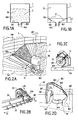
- FIGS. 2A to 2D at the end of the present description illustrate very schematically an example of such a device and its mode of operation.
- identical elements bear the same references and will only be re-described as needed.
- the device with "integral drain screw”, referenced 3 is constituted mainly a beam 31 and a worm 32 ( Figures 2B and 2C).
- the device 3 is rotatably mounted with respect to a vertical axis ⁇ V located at center of silo 1. It is intended to evacuate radially and continuously the product residual 2 'in a hopper 102 located in the immediate vicinity of this vertical axis central ⁇ V.
- Figure 2A partially illustrates, in view of three quarters high, the bottom silo 1 and the residual volume of product 2 ', of conical shape, in progress final extraction using the device 3.
- the function of the motorization member 30 is to rotate the worm 32, via an angle gear (not shown), about a horizontal axis ⁇ H, longitudinal to the beam 31, as illustrated more particularly in FIG. 2B (partial view in the space of the end of the beam 31) or FIG. 2C (which is seen in section, from the side, of this same beam 31 and of the worm 32) .
- the rotation is effected, in the illustrated example, in the direction of clockwise: arrow f 1, by rotating a drive shaft 320 of the worm 32. It follows that the residual product 2 'is intercepted by the worm 32 and pushed towards the center (arrow f2), parallel to the axis ⁇ H, to fall into the central hopper 102.
- this end wheel 33 participates in the rotational drive of the beam 31 about the axis ⁇ V in the direction of clockwise. It suffices to provide coupling members 330 (in the example a reduction gearbox) to the rotation shaft 320 of the worm screw 32. When the wheel 33 rotates (arrow f 3), it pushes the end of the beam 31. This therefore describes a circle of radius substantially equal to that of the cylindrical wall 100 of the silo 1.
- silo bottom 101 perfectly flat. It follows that, in practice, the substance Silo 101 still has imperfections of flatness and / or parts such as, for example, ventilation grilles 104 (FIG. 2A), generally, level variations.
- the beam 31 being rigid, it follows that it is necessary to provide a play to avoid any risk of blockage and allow it a full rotation of around the central vertical axis ⁇ V.
- a hinge member of the beam 31 can be provided, as illustrated more particularly by 2D, a hinge member of the beam 31.
- the organ of motorization itself is disposed under the bottom wall 101. in particular drives the worm 32 in rotation through a angle gear whose bottom base 300 serves as a central support for the screw of integral emptying on the bottom wall 101 and rotation pivot of the beam around the ⁇ V axis.
- a first pair of side pieces 303 subject to a angle gear (not shown), support a shaft 302 in free rotation around a horizontal axis ⁇ H ', orthogonal to the axis ⁇ H.
- the beam 31 is secured to the shaft 302 by a second pair of side support pieces 301. As a result, it can oscillate around the ⁇ H 'axis and accommodate surface irregularities of the bottom wall 101.
- the layer of residual product to evacuate manually in a silo cell 1 with a typical diameter of 28 meters represents about 25 tons.
- the invention aims to overcome the disadvantages of the devices of the art known and to meet the needs that are felt, and some of which come to be called back.
- the object of the invention is to provide an automatic cleaning device for the bottom wall of a silo, the latter being of the type with a substantially flat bottom and intended to store grain-like products or similar products likely to be extracted by a gravitational natural flow.
- the device essentially comprises a spiral brush or, more generally, a spiral squeegee, fitted with a protective fairing.
- this element will be called hereinafter "brush”.
- the brush is mechanically coupled to a aforesaid worm discharge device or similar device.
- the cleaning device is arranged at the rear of the emptying device, by relative to the direction of rotation about the vertical axis. Because of this, the brush intercepts and evacuates the remaining product in the same central hopper after passage of the drain screw or any other organ in acting.
- the brush is driven by the drive member of the integral drain screw, via appropriate transmission devices which will be detailed below.
- the silo In the first two cases, it remains permanently in the silo. In the third case, it can be disassembled after use and stored in a room appropriate technique and, therefore, not remain permanently in the silo, which represents a definite advantage.
- the subject of the invention is therefore a device for cleaning a silo with a substantially flat bottom for storing a grain product or similar, said silo comprising on a bottom wall, in a central zone, an orifice through which said product is drainable natural gravity during an initial phase of extraction, leaving on bottom wall a first residual volume of said product, said silo being provided a device for emptying in rotation about a vertical axis passing through the said central zone, sweeping during said rotation said bottom wall, so as to intercept and transport to said central orifice the essential of said first residual volume of product, during a second extraction phase, leaving a second residual volume, said final, said product on said bottom wall, characterized in that it is subject to said draining device, so as to follow said rotational movement about said vertical axis, in that comprises a shaft supporting a spiral squeegee resting on said wall of basically, in that it includes motorization means printing a rotational movement of said support shaft and said squeegee about an axis substantially horizontal, in that
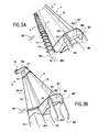
- Figure 3A illustrates in space, in partial view of three quarters top, the cleaning device itself, referenced 4, not carinated, to mainly know a spiral brush 40 (or more generally, like it has been indicated, a spiral squeegee) carried by a drive shaft allowing rotation about a horizontal axis ⁇ H4 parallel to the axis of rotation ⁇ H of the worm 32 ( Figures 2B and 2C).
- a spiral brush 40 or more generally, like it has been indicated, a spiral squeegee
- the device 4 is attached to a device of the screw type drain integral 3, which may be otherwise identical at least very similar in itself with the device of the type known in the art described in Figures 2A to 2C. Only a few Minor adaptations are necessary and will be specified below.
- the drive member of the screw device of emptying 3 is not visible because disposed below the bottom wall 101. This configuration is similar to that described with reference to FIG. 2D.
- FIG. 3A also shows the articulation member of the beam 31 comprising two pairs of lateral supports, 301 and 303, and the shaft 302 allowing oscillation (rotation) about the axis ⁇ H '.
- the wiper discharge device 32 (FIG. 2B) intercepts most of the volume of residual product 2 '(FIG. 2A) remaining after the natural gravity extraction and the expulsion to the central hopper 102, precisely through the worm 32 ( Figures 2B and 2C).
- the wiper discharge device 32 intercepts most of the volume of residual product 2 '(FIG. 2A) remaining after the natural gravity extraction and the expulsion to the central hopper 102, precisely through the worm 32 ( Figures 2B and 2C).
- there remains a layer of residual product that will be called “final”, now referenced 2 " which has not been intercepted because of oscillations of the beam 31 about the axis ⁇ H ', themselves resulting from the non-flatness of the bottom wall 101.
- This final residual product 2 " is found on the rear of the worm 32.
- the residual product 2 "is intercepted by the spiral brush 40. It is pushed forward considering the direction of travel, the spiral brush 40 rotating in opposite direction (arrow f 4) in the direction of advance (arrow f ) In any case, it is conveyed simultaneously to the central hopper 102, again because of the rotation of the spiral brush 40 about the axis ⁇ H4 .
- the residual 2 is of relatively small thickness after passage of the device 3, on the other hand, even in the presence of oscillations of the beam 31 (which lead to oscillations of the same order of magnitude of the cleaning device), these Oscillations are small amplitudes. It follows that they can be absorbed by the elasticity of the hairs of the spiral brush 40. This rests so permanently on the bottom wall 101 of the silo over its entire length and operates a continuous cleaning.
- Figure 3B is a representation in space, in view of three-quarters top showing more fully the combined system combining the worm discharge device 3 and brush cleaning device 4 spiral 40 according to the invention.
- This fairing 42 is subject to the beam 31 by various means of fasteners: flange 45, in an area near the central end, one or several pieces of intermediate support (s) 44 arranged along the beam 42 and connected (s) to the beam 31.
- the fairing 42 to the inner form of a "C" reversed.
- FIG. 3B also shows the end wheel 33, common now to the device of type integral screw emptying 3 and the Automatic cleaning device 4 with spiral brush 40.
- end wheel 33 common now to the device of type integral screw emptying 3 and the Automatic cleaning device 4 with spiral brush 40.
- intermediate wheels can be provided, especially if the length of the beams 31 and 42 is important.
- FIG. 3C is a detail figure illustrating more precisely a embodiment of an intermediate support 44. It comprises a flange 442 secured to the beam 31. Two lateral flanges 440 are attached thereto by any suitable means 443 (screwing, etc.). Between these flanges 440, forming supports, there is an intermediate bearing 441 in turn supporting the shaft rotation 41 of the spiral brush 40.
- the spiral brush 40 is represented more Detailed. It comprises a central frame 401 consisting of a screw without end with no left, supporting, at the periphery, flexible bristles or, more generally, of flexible elements, 400, of material compatible with the applications envisaged (in particular with the nature of the products stored).
- the length of the bristles 400 and their flexibility are determined in particular for absorb the oscillations of the two beams during their rotation around the axis ⁇ V (FIGS. 3A and 3B), so that the spiral brush 40 remains constantly in contact with the bottom wall 101.
- This arrangement is illustrated schematically by the figure of 3D detail.
- This sealing means is in the form of an organ that it will be called “sealing lip" 5 disposed between the two beams, 31 and 42, and secured thereto through seals, 50 and 51, respectively.
- a cleaning member auxiliary brush linear (or more generally a linear squeegee) to contain the residual product 2 "(FIG. 3C) filling the space between the cleaning beam 42 and the bottom wall 101.
- This member 6 comprises a linear brush 60 (more generally linear flexible elements) and a support profile 61, subjected by all suitable means (screwing, etc.) 610 to the rear wall of the beam 42.
- the means for rotating the shaft 41 (FIGS. 3A or 3C) of the brush spiral 40 are derived from those specific to emptying device with integral drain screw 3, by means of mechanical coupling which will be specified below.
- FIG. 3F illustrates these mechanical coupling means 7, in the space in rear view.
- the means of motorization proper are arranged below the bottom wall 101 (see FIG. 2D: 30).
- the coupling means 7 comprise a transmission housing 70 subjected to the two beams, 31 and 42.
- the mechanical coupling is carried out, for the shaft 320 (FIG. 2C) on a first output shaft of the housing 7, by through an angle gear mechanism and the gear 73.
- the shaft 41 of the spiral brush 40 is driven counterclockwise by the gear 72 (the worm 32 of the integral drain 3 being driven clockwise), on a second output axis of the housing 7.
- the two gears are physically coupled using a chain 71.
- intermediate gears are provided: at 76.
- the gear 74 also acts as a chain tensioner, with the aid of a tensioning member 740.
- a cover and sealing means are provided (not shown) to close the transmission housing 7.
- this transmission housing 7 can be replaced by another means of driving the spiral screw 40: geared motor, hydraulic motor, etc., according to the drain screw device set which may differ from that described with reference to FIGS. 2A to 2D without depart from the scope of the invention.
- the transmission housing 7 is not rendered secured to the beam 31 of the emptying device 3 with worm 32, but side pieces, 303, horizontal oscillation axis supports, 302, of the beam 31 (see FIGS. 3A and 3B).
- the beam 42 of the cleaning device 4 to spiral brush 40 itself being fixedly attached to the beam 31, it is necessary that it can follow the oscillation movements of the latter.
- a system 8 articulated transmission connecting the shaft 41 of the spiral cleaning brush 40 to the output shaft 720 of the housing of transmission 7.
- This output shaft 720 is rotated by the gear 72 ( Figure 3F).
- the articulated transmission 82 is of the type at the Cardan.
- the spiral brush and the endless screws are not in contact with each other and their speeds respective are different, or at least made different as of need.
- the beam 31 and the fairing 42 are, during the product phase to the central hopper 102, completely independent and form two sets autonomous.
- the only links are constituted by sealing elements and the coupling of the beam 31 causing rotation around the vertical axis ⁇ V the device comprising the fairing and the spiral brush 40.
- the drive shaft 41 of the spiral brush 40 is equipped, on the end close to the hinge 82, a net member 80 mounted on a shaft 81, extending the shaft 41 and mechanically subject thereto.
- pallets 84 or any other means of ejection are provided. similar to the final residual product 2 "to the discharge hopper 102, when the end of the trees 41-81 are outside of the latter.
- protection means are provided for this joint in the form of a sheet metal casing 83 which covers it, which allows it to be protected during the gravity drain phase, as shown in more particularly in Figure 3H.
- the cleaning device according to the invention can be integrated with a drain device at the time of manufacture in the factory or in addition to a pre-existing device, with in-situ modifications of little complexity, or be removable.
Landscapes
- Engineering & Computer Science (AREA)
- Mechanical Engineering (AREA)
- Filling Or Emptying Of Bunkers, Hoppers, And Tanks (AREA)
- Catching Or Destruction (AREA)
- Developing Agents For Electrophotography (AREA)
- Display Devices Of Pinball Game Machines (AREA)
- Adjustment And Processing Of Grains (AREA)
Abstract
Description
- être intégré à un dispositif nouveau du type à vidange intégrale au moment de sa fabrication ;
- être ajouté à un dispositif déjà existant du type à vidange intégrale ; ou
- être amovible : il est dans ce cas connecté à un dispositif déjà existant du type à vidange intégrale lors de son utilisation.
- les figures 1A et 1B illustrent schématiquement l'état d'un silo plein de grains et l'état atteint lorsque ce grain a été extrait par le simple effet de la gravité, respectivement ;
- la figure 2A illustre partiellement, en vue de trois quarts hauts, un silo muni d'un dispositif de vidange de grains résiduels dit à "vis de vidange intégrale" selon l'art connu, et explicite le fonctionnement de ce dispositif ;
- les figures 2B à 2D illustrent schématiquement des détails de ce dispositif ;
- les figures 3A et 3B illustrent schématiquement dans l'espace, en vue de trois quarts hauts, un exemple de dispositif de nettoyage à raclette spiralée selon un mode de réalisation préférée de l'invention, sans carénage de protection et avec un tel carénage, respectivement ;
- la figure 3C est une figure de détail illustrant un palier intermédiaire utilisé dans le dispositif des figures 3A et 3B ;
- la figure 3D est une figure de détail illustrant un élément d'étanchéité disposé entre le dispositif de vidange des figures 2A à 2D et le dispositif de nettoyage selon l'invention ;
- la figure 3E est une figure de détail illustrant un élément de type balai linéaire disposé sur le carénage du dispositif de nettoyage selon l'invention ;
- la figure 3F est une figure de détail illustrant un boítier de transmission couplant mécaniquement les arbres d'entraínement des dispositifs de vidange et de nettoyage ; et
- les figures 3G et 3H sont des figures de détail illustrant un système de transmission articulée reliant l'arbre d'entraínement de la raclette spiralée du dispositif de nettoyage à un arbre de sortie du boítier de transmission de la figure 3F.
Claims (14)
- Dispositif de nettoyage d'un silo à fond sensiblement plat destiné à stocker un produit de type grains ou similaires, ledit silo comprenant sur une paroi de fond, dans une zone centrale, un orifice par lequel ledit produit est susceptible d'être vidé par écoulement gravitaire naturel lors d'une première phase d'extraction, en laissant sur ladite paroi de fond un premier volume résiduel dudit produit, ledit silo étant muni d'un dispositif de vidange en rotation autour d'un axe vertical passant par ladite zone centrale, balayant lors de ladite rotation ladite paroi de fond, de manière à intercepter et à transporter vers ledit orifice central l'essentiel dudit premier volume résiduel de produit, lors d'une deuxième phase d'extraction, laissant un deuxième volume résiduel, dit final, dudit produit sur ladite paroi de fond, caractérisé en ce qu'il est assujetti au dit dispositif de vidange (3), de manière à suivre ledit mouvement de rotation autour dudit axe vertical (ΔV), en ce qu'il comprend un arbre (41) supportant un raclette spiralée (40) reposant sur ladite paroi de fond (101), en ce qu'il comprend des moyens de motorisation imprimant un mouvement de rotation dudit arbre support (41) et de ladite raclette (40) autour d'un axe sensiblement horizontal (ΔH4), en ce que le sens de ladite rotation est tel que ladite raclette spiralée (40) intercepte et expulse ledit deuxième volume résiduel de produit (2") vers ledit orifice central (102), de manière à obtenir un nettoyage automatique de ladite paroi de fond (101) et un extraction totale dudit produit (2"), et en ce que ledit dispositif de vidange (3) comprend un arbre d'entraínement (320) assujetti au dit arbre support (41) par des moyens mécaniques articulés (8), de manière à obtenir un découplage entre lesdits arbres (41, 320).
- Dispositif selon la revendication 1, caractérisé en ce que ladite raclette spiralée (40) est constituée d'une armature centrale (401) en forme de vis sans fin enroulée autour dudit arbre support (41) et munie en périphérie d'éléments souples (400).
- Dispositif selon les revendications 1 ou 2, caractérisé en ce que ledit dispositif de vidange (3) comprend ledit arbre d'entraínement (320) supportant une vis sans fin (32) et des moyens de motorisation (30) imprimant un mouvement de rotation à ladite vis sans fin (32) autour d'un axe sensiblement horizontal (ΔH), et en ce que ledit dispositif de vidange (3) comprend un carénage de protection enveloppant ladite vis sans fin (32) sur le dessus, ayant la forme générale d'un "C" renversé, et formant une première poutre rigide (31), ladite vis sans fin (32) interceptant et transportant vers ledit orifice central (102) l'essentiel dudit premier volume résiduel de produit (2'), lors de ladite deuxième phase d'extraction, laissant ledit deuxième volume résiduel final de produit (2") sur ladite paroi de fond (101), dans une zone dite de sortie par rapport au sens de ladite rotation autour dudit axe vertical (ΔV), de manière à ce que ce dit deuxième volume de produit résiduel (2") soit intercepté à son tour par ladite raclette spiralée (40).
- Dispositif selon la revendication 3, caractérisé en ce que ledit arbre d'entraínement (41) supportant ladite raclette spiralée (40) est muni d'au moins un palier intermédiaire (441) assujetti mécaniquement à ladite première poutre rigide (31) par des pièces supports latérales (440) et une bride (442) entourant tout ou partie de ladite poutre rigide (31 ).
- Dispositif selon les revendications 3 ou 4, caractérisé en ce que les énergies nécessaires à la motorisation dudit arbre (41) supportant ladite raclette spiralée (40) et dudit arbre (320) supportant ladite vis sans fin (32) sont dérivés de moyens de motorisation communs (30) et en ce que ces moyens de motorisation (30) sont couplés à un boítier de transmission (7) permettant un couplage desdits arbres (41, 320) par l'intermédiaire de premier et deuxième arbres de sortie (720) et d'un mécanisme de renvoi d'angle.
- Dispositif selon la revendication 5, caractérisé en ce que ledit couplage est obtenu par l'intermédiaire d'une chaíne de transmission (71) et d'engrenages (72-76), lesdits engrenages (72-76) imprimant un mouvement dans le sens d'une montre au dit arbre d'entraínement (320) supportant ladite vis sans fin (32) et un mouvement anti-horaire au dit arbre d'entraínement (720) supportant ladite raclette spiralée (40).
- Dispositif selon l'une quelconque des revendications 3 à 6, caractérisé en ce qu'il comprend également un carénage de protection enveloppant ladite raclette spiralé sur le dessus, ayant la forme générale d'un "C" renversé, et formant une deuxième poutre rigide (42), et en ce que lesdits carénages desdites première et deuxième poutres rigides (31, 42) sont reliés entre eux, dans une zone supérieure, par un élément d'étanchéité (5).
- Dispositif selon la revendication 7, caractérisé en ce que ledit carénage de la dite deuxième poutre rigide (42) est muni, dans une zone inférieure, opposée à ladite première poutre rigide (31), dite de sortie par rapport au sens de ladite rotation autour dudit axe vertical (ΔV), d'un élément de nettoyage auxiliaire comprenant des éléments souples linéaires (6) balayant ladite paroi de fond (101) lors de ladite rotation autour de cet axe vertical (ΔV).
- Dispositif selon l'une quelconque des revendications 3 à 8, caractérisé en ce que ladite première poutre (31) est munie, en une extrémité proche de ladite zone centrale, de moyens (301-303) permettant des oscillations autour d'un axe horizontal (ΔH'), de manière à pouvoir accommoder des variations de niveau de ladite paroi de fond (101) lors de ladite rotation autour dudit axe vertical (ΔV).
- Dispositif selon la revendication 9, caractérisé en ce que lesdits moyens permettant des oscillations comprennent deux paires pièces supports latérales verticales (301-303) couplées par un arbre (302) permettant des rotations libres autour dudit axe horizontal (ΔH').
- Dispositif selon la revendication 10, caractérisé en ce que ledit arbre d'entraínement (41) supportant ladite raclette spiralée (40) est couplé mécaniquement sur ledit deuxième arbre de sortie (720) dudit boítier de transmission (7) par l'intermédiaire d'un élément de transmission articulé (8).
- Dispositif selon la revendication 11, caractérisé en ce que ledit élément de transmission articulé est une transmission à la Cardan (8).
- Dispositif selon la revendication 12, caractérisé en ce que l'extrémité proche de ladite zone centrale dudit arbre d'entraínement (41) supportant ladite raclette spiralée (40) est munie d'un élément à vis sans fin (80) muni de moyens d'éjection (84) dudit produit (2") dudit deuxième volume résiduel final vers ledit orifice central (102).
- Dispositif selon l'une quelconque des revendications 11 à 13, caractérisé en ce que ledit élément de transmission articulé (8) est muni d'un carénage de protection (83) ayant la forme générale d'un "C" renversé.
Applications Claiming Priority (2)
| Application Number | Priority Date | Filing Date | Title |
|---|---|---|---|
| FR0350546A FR2859715B1 (fr) | 2003-09-16 | 2003-09-16 | Dispositif de nettoyage d'un silo a fond sensiblement plat destine a stocker des grains s'ecoulant naturellement par gravite |
| FR0350546 | 2003-09-16 |
Publications (2)
| Publication Number | Publication Date |
|---|---|
| EP1516836A1 true EP1516836A1 (fr) | 2005-03-23 |
| EP1516836B1 EP1516836B1 (fr) | 2008-07-16 |
Family
ID=34179000
Family Applications (1)
| Application Number | Title | Priority Date | Filing Date |
|---|---|---|---|
| EP04300595A Expired - Lifetime EP1516836B1 (fr) | 2003-09-16 | 2004-09-13 | Dispositif de vidange d'un silo à fond sensiblement plat |
Country Status (4)
| Country | Link |
|---|---|
| EP (1) | EP1516836B1 (fr) |
| AT (1) | ATE401277T1 (fr) |
| DE (1) | DE602004015031D1 (fr) |
| FR (1) | FR2859715B1 (fr) |
Cited By (4)
| Publication number | Priority date | Publication date | Assignee | Title |
|---|---|---|---|---|
| CN103159037A (zh) * | 2011-12-19 | 2013-06-19 | 上海良友(集团)有限公司 | 组合输送颗粒出料机 |
| CN108217237A (zh) * | 2018-01-25 | 2018-06-29 | 哈尔滨峰雷电力设备制造有限公司 | 火车、汽车螺旋卸车机残煤清扫装置 |
| US10017338B2 (en) | 2010-02-19 | 2018-07-10 | Sudenga Industries, Inc. | Bin sweep collector ring assembly |
| CN108545497A (zh) * | 2018-04-16 | 2018-09-18 | 安徽合众智信科技咨询有限公司 | 用于泥浆输送且可减少底部残留的无轴螺旋输送机 |
Families Citing this family (2)
| Publication number | Priority date | Publication date | Assignee | Title |
|---|---|---|---|---|
| EP1806305A1 (fr) * | 2006-01-06 | 2007-07-11 | Etablissements DENIS | Dispositif de nettoyage de la paroi de fond d'un silo |
| CN101215607B (zh) * | 2008-01-08 | 2010-06-16 | 中国农业大学 | 一种检测鸡蛋鱼腥味突变等位基因的方法及其试剂盒 |
Citations (6)
| Publication number | Priority date | Publication date | Assignee | Title |
|---|---|---|---|---|
| US2037959A (en) * | 1934-04-26 | 1936-04-21 | Internat Milling Company | Apparatus for handling bulk materials |
| FR2517285A2 (fr) * | 1981-11-27 | 1983-06-03 | Denis Ets Sa | Perfectionnement a la vis de balayage du grain dans une cellule cylindrique de silo |
| US4619577A (en) * | 1984-11-20 | 1986-10-28 | Lynos Swanson | Sweep auger |
| US4875820A (en) * | 1988-03-30 | 1989-10-24 | Lepp Henry P | Convertible grain bin sweep unloader |
| US5960932A (en) * | 1998-01-07 | 1999-10-05 | Nomura Enterprise Inc. | Sweep auger handle |
| US6254329B1 (en) * | 2000-05-31 | 2001-07-03 | Sukup Manufacturing Company | Sweep auger |
-
2003
- 2003-09-16 FR FR0350546A patent/FR2859715B1/fr not_active Expired - Lifetime
-
2004
- 2004-09-13 EP EP04300595A patent/EP1516836B1/fr not_active Expired - Lifetime
- 2004-09-13 AT AT04300595T patent/ATE401277T1/de not_active IP Right Cessation
- 2004-09-13 DE DE602004015031T patent/DE602004015031D1/de not_active Expired - Lifetime
Patent Citations (6)
| Publication number | Priority date | Publication date | Assignee | Title |
|---|---|---|---|---|
| US2037959A (en) * | 1934-04-26 | 1936-04-21 | Internat Milling Company | Apparatus for handling bulk materials |
| FR2517285A2 (fr) * | 1981-11-27 | 1983-06-03 | Denis Ets Sa | Perfectionnement a la vis de balayage du grain dans une cellule cylindrique de silo |
| US4619577A (en) * | 1984-11-20 | 1986-10-28 | Lynos Swanson | Sweep auger |
| US4875820A (en) * | 1988-03-30 | 1989-10-24 | Lepp Henry P | Convertible grain bin sweep unloader |
| US5960932A (en) * | 1998-01-07 | 1999-10-05 | Nomura Enterprise Inc. | Sweep auger handle |
| US6254329B1 (en) * | 2000-05-31 | 2001-07-03 | Sukup Manufacturing Company | Sweep auger |
Cited By (7)
| Publication number | Priority date | Publication date | Assignee | Title |
|---|---|---|---|---|
| US10017338B2 (en) | 2010-02-19 | 2018-07-10 | Sudenga Industries, Inc. | Bin sweep collector ring assembly |
| US11008186B2 (en) | 2010-02-19 | 2021-05-18 | Sudenga Industries, Inc. | Bin sweep collector ring assembly |
| CN103159037A (zh) * | 2011-12-19 | 2013-06-19 | 上海良友(集团)有限公司 | 组合输送颗粒出料机 |
| CN103159037B (zh) * | 2011-12-19 | 2016-06-15 | 上海良友(集团)有限公司 | 组合输送颗粒出料机 |
| CN108217237A (zh) * | 2018-01-25 | 2018-06-29 | 哈尔滨峰雷电力设备制造有限公司 | 火车、汽车螺旋卸车机残煤清扫装置 |
| CN108217237B (zh) * | 2018-01-25 | 2023-10-17 | 哈尔滨峰雷电力设备制造有限公司 | 火车、汽车螺旋卸车机残煤清扫装置 |
| CN108545497A (zh) * | 2018-04-16 | 2018-09-18 | 安徽合众智信科技咨询有限公司 | 用于泥浆输送且可减少底部残留的无轴螺旋输送机 |
Also Published As
| Publication number | Publication date |
|---|---|
| ATE401277T1 (de) | 2008-08-15 |
| FR2859715A1 (fr) | 2005-03-18 |
| FR2859715B1 (fr) | 2006-12-01 |
| DE602004015031D1 (de) | 2008-08-28 |
| EP1516836B1 (fr) | 2008-07-16 |
Similar Documents
| Publication | Publication Date | Title |
|---|---|---|
| EP1611007B1 (fr) | Propulseur retractable par rotation | |
| LU83279A1 (fr) | Installation de chargement d'un four a cuve | |
| CA1192158A (fr) | Dispositifs d'extraction de matieres solides en vrac a l'etat finement divise depuis le fond d'un silo | |
| EP3526147B1 (fr) | Système comprenant un silo et une vis balayeuse | |
| FR2504240A1 (fr) | Mecanisme de conversion de transmission pour soufflante de suie | |
| EP1516836B1 (fr) | Dispositif de vidange d'un silo à fond sensiblement plat | |
| EP3794961A1 (fr) | Érafloir stationnaire pour un équipement de vinification | |
| EP1391702A2 (fr) | Machine doseuse | |
| FR2893517A1 (fr) | Godet permettant de melanger et de distribuer des produits granulaires ou fibreux en vrac destines par exemple a l'alimentation du betail. | |
| FR2634305A1 (fr) | Appareil distributeur de produits plats a enroulements en helice rotatifs | |
| EP1640501B1 (fr) | Dispositif d'épandage de matiere granuleuse ou pulvérulente | |
| EP1530891B1 (fr) | Dispositif de dosage et de distribution de graines pour semoir | |
| EP0955255B1 (fr) | Dispositif extracteur à vis sans fin, pourvu de moyens d'entraínement en rotation améliorée | |
| EP2380656B1 (fr) | Godet pourvu d'un organe de mélange et/ou de distribution à double entraînement | |
| FR2767634A1 (fr) | Godet desileur | |
| FR2506360A1 (fr) | Balayeuse mobile | |
| EP1806305A1 (fr) | Dispositif de nettoyage de la paroi de fond d'un silo | |
| FR2754776A1 (fr) | Vehicule de transport a bachage lateral | |
| FR2664508A1 (fr) | Centrifugeuse a fonctionnement continu. | |
| FR2828179A1 (fr) | Procede et dispositif de vidange de silo | |
| FR2727096A1 (fr) | Tremie d'alimentation a bande | |
| FR2890284A1 (fr) | Ensileuse pour silo-boudin | |
| FR2819146A1 (fr) | Machine portee permettant le chargement, le melange et la distribution de produits divers | |
| FR2778396A1 (fr) | Perfectionnements aux extracteurs a vis sur silos | |
| FR2856668A1 (fr) | Extracteur a vis sans fin comportant un arbre central |
Legal Events
| Date | Code | Title | Description |
|---|---|---|---|
| PUAI | Public reference made under article 153(3) epc to a published international application that has entered the european phase |
Free format text: ORIGINAL CODE: 0009012 |
|
| AK | Designated contracting states |
Kind code of ref document: A1 Designated state(s): AT BE BG CH CY CZ DE DK EE ES FI FR GB GR HU IE IT LI LU MC NL PL PT RO SE SI SK TR |
|
| AX | Request for extension of the european patent |
Extension state: AL HR LT LV MK |
|
| 17P | Request for examination filed |
Effective date: 20050906 |
|
| AKX | Designation fees paid |
Designated state(s): AT BE BG CH CY CZ DE DK EE ES FI FR GB GR HU IE IT LI LU MC NL PL PT RO SE SI SK TR |
|
| 17Q | First examination report despatched |
Effective date: 20051216 |
|
| GRAP | Despatch of communication of intention to grant a patent |
Free format text: ORIGINAL CODE: EPIDOSNIGR1 |
|
| GRAS | Grant fee paid |
Free format text: ORIGINAL CODE: EPIDOSNIGR3 |
|
| GRAA | (expected) grant |
Free format text: ORIGINAL CODE: 0009210 |
|
| AK | Designated contracting states |
Kind code of ref document: B1 Designated state(s): AT BE BG CH CY CZ DE DK EE ES FI FR GB GR HU IE IT LI LU MC NL PL PT RO SE SI SK TR |
|
| REG | Reference to a national code |
Ref country code: GB Ref legal event code: FG4D Free format text: NOT ENGLISH |
|
| REG | Reference to a national code |
Ref country code: CH Ref legal event code: EP |
|
| REF | Corresponds to: |
Ref document number: 602004015031 Country of ref document: DE Date of ref document: 20080828 Kind code of ref document: P |
|
| REG | Reference to a national code |
Ref country code: IE Ref legal event code: FG4D Free format text: LANGUAGE OF EP DOCUMENT: FRENCH |
|
| NLV1 | Nl: lapsed or annulled due to failure to fulfill the requirements of art. 29p and 29m of the patents act | ||
| PG25 | Lapsed in a contracting state [announced via postgrant information from national office to epo] |
Ref country code: ES Free format text: LAPSE BECAUSE OF FAILURE TO SUBMIT A TRANSLATION OF THE DESCRIPTION OR TO PAY THE FEE WITHIN THE PRESCRIBED TIME-LIMIT Effective date: 20081027 Ref country code: PT Free format text: LAPSE BECAUSE OF FAILURE TO SUBMIT A TRANSLATION OF THE DESCRIPTION OR TO PAY THE FEE WITHIN THE PRESCRIBED TIME-LIMIT Effective date: 20081216 Ref country code: NL Free format text: LAPSE BECAUSE OF FAILURE TO SUBMIT A TRANSLATION OF THE DESCRIPTION OR TO PAY THE FEE WITHIN THE PRESCRIBED TIME-LIMIT Effective date: 20080716 |
|
| PG25 | Lapsed in a contracting state [announced via postgrant information from national office to epo] |
Ref country code: SI Free format text: LAPSE BECAUSE OF FAILURE TO SUBMIT A TRANSLATION OF THE DESCRIPTION OR TO PAY THE FEE WITHIN THE PRESCRIBED TIME-LIMIT Effective date: 20080716 Ref country code: BG Free format text: LAPSE BECAUSE OF FAILURE TO SUBMIT A TRANSLATION OF THE DESCRIPTION OR TO PAY THE FEE WITHIN THE PRESCRIBED TIME-LIMIT Effective date: 20081016 Ref country code: FI Free format text: LAPSE BECAUSE OF FAILURE TO SUBMIT A TRANSLATION OF THE DESCRIPTION OR TO PAY THE FEE WITHIN THE PRESCRIBED TIME-LIMIT Effective date: 20080716 Ref country code: AT Free format text: LAPSE BECAUSE OF FAILURE TO SUBMIT A TRANSLATION OF THE DESCRIPTION OR TO PAY THE FEE WITHIN THE PRESCRIBED TIME-LIMIT Effective date: 20080716 |
|
| REG | Reference to a national code |
Ref country code: IE Ref legal event code: FD4D |
|
| BERE | Be: lapsed |
Owner name: ETS DENIS Effective date: 20080930 |
|
| PG25 | Lapsed in a contracting state [announced via postgrant information from national office to epo] |
Ref country code: DK Free format text: LAPSE BECAUSE OF FAILURE TO SUBMIT A TRANSLATION OF THE DESCRIPTION OR TO PAY THE FEE WITHIN THE PRESCRIBED TIME-LIMIT Effective date: 20080716 Ref country code: EE Free format text: LAPSE BECAUSE OF FAILURE TO SUBMIT A TRANSLATION OF THE DESCRIPTION OR TO PAY THE FEE WITHIN THE PRESCRIBED TIME-LIMIT Effective date: 20080716 Ref country code: MC Free format text: LAPSE BECAUSE OF NON-PAYMENT OF DUE FEES Effective date: 20080930 Ref country code: IE Free format text: LAPSE BECAUSE OF FAILURE TO SUBMIT A TRANSLATION OF THE DESCRIPTION OR TO PAY THE FEE WITHIN THE PRESCRIBED TIME-LIMIT Effective date: 20080716 |
|
| REG | Reference to a national code |
Ref country code: CH Ref legal event code: PL |
|
| PLBE | No opposition filed within time limit |
Free format text: ORIGINAL CODE: 0009261 |
|
| STAA | Information on the status of an ep patent application or granted ep patent |
Free format text: STATUS: NO OPPOSITION FILED WITHIN TIME LIMIT |
|
| PG25 | Lapsed in a contracting state [announced via postgrant information from national office to epo] |
Ref country code: SK Free format text: LAPSE BECAUSE OF FAILURE TO SUBMIT A TRANSLATION OF THE DESCRIPTION OR TO PAY THE FEE WITHIN THE PRESCRIBED TIME-LIMIT Effective date: 20080716 Ref country code: CZ Free format text: LAPSE BECAUSE OF FAILURE TO SUBMIT A TRANSLATION OF THE DESCRIPTION OR TO PAY THE FEE WITHIN THE PRESCRIBED TIME-LIMIT Effective date: 20080716 Ref country code: RO Free format text: LAPSE BECAUSE OF FAILURE TO SUBMIT A TRANSLATION OF THE DESCRIPTION OR TO PAY THE FEE WITHIN THE PRESCRIBED TIME-LIMIT Effective date: 20080716 |
|
| 26N | No opposition filed |
Effective date: 20090417 |
|
| GBPC | Gb: european patent ceased through non-payment of renewal fee |
Effective date: 20081016 |
|
| REG | Reference to a national code |
Ref country code: FR Ref legal event code: ST Effective date: 20090529 |
|
| PG25 | Lapsed in a contracting state [announced via postgrant information from national office to epo] |
Ref country code: BE Free format text: LAPSE BECAUSE OF NON-PAYMENT OF DUE FEES Effective date: 20080930 |
|
| PG25 | Lapsed in a contracting state [announced via postgrant information from national office to epo] |
Ref country code: IT Free format text: LAPSE BECAUSE OF FAILURE TO SUBMIT A TRANSLATION OF THE DESCRIPTION OR TO PAY THE FEE WITHIN THE PRESCRIBED TIME-LIMIT Effective date: 20080716 |
|
| PG25 | Lapsed in a contracting state [announced via postgrant information from national office to epo] |
Ref country code: CH Free format text: LAPSE BECAUSE OF NON-PAYMENT OF DUE FEES Effective date: 20080930 Ref country code: FR Free format text: LAPSE BECAUSE OF NON-PAYMENT OF DUE FEES Effective date: 20080930 Ref country code: LI Free format text: LAPSE BECAUSE OF NON-PAYMENT OF DUE FEES Effective date: 20080930 |
|
| PG25 | Lapsed in a contracting state [announced via postgrant information from national office to epo] |
Ref country code: GB Free format text: LAPSE BECAUSE OF NON-PAYMENT OF DUE FEES Effective date: 20081016 |
|
| PG25 | Lapsed in a contracting state [announced via postgrant information from national office to epo] |
Ref country code: SE Free format text: LAPSE BECAUSE OF FAILURE TO SUBMIT A TRANSLATION OF THE DESCRIPTION OR TO PAY THE FEE WITHIN THE PRESCRIBED TIME-LIMIT Effective date: 20081016 |
|
| PG25 | Lapsed in a contracting state [announced via postgrant information from national office to epo] |
Ref country code: PL Free format text: LAPSE BECAUSE OF FAILURE TO SUBMIT A TRANSLATION OF THE DESCRIPTION OR TO PAY THE FEE WITHIN THE PRESCRIBED TIME-LIMIT Effective date: 20080716 |
|
| PG25 | Lapsed in a contracting state [announced via postgrant information from national office to epo] |
Ref country code: LU Free format text: LAPSE BECAUSE OF NON-PAYMENT OF DUE FEES Effective date: 20080913 Ref country code: CY Free format text: LAPSE BECAUSE OF FAILURE TO SUBMIT A TRANSLATION OF THE DESCRIPTION OR TO PAY THE FEE WITHIN THE PRESCRIBED TIME-LIMIT Effective date: 20080716 Ref country code: HU Free format text: LAPSE BECAUSE OF FAILURE TO SUBMIT A TRANSLATION OF THE DESCRIPTION OR TO PAY THE FEE WITHIN THE PRESCRIBED TIME-LIMIT Effective date: 20090117 |
|
| PG25 | Lapsed in a contracting state [announced via postgrant information from national office to epo] |
Ref country code: TR Free format text: LAPSE BECAUSE OF FAILURE TO SUBMIT A TRANSLATION OF THE DESCRIPTION OR TO PAY THE FEE WITHIN THE PRESCRIBED TIME-LIMIT Effective date: 20080716 |
|
| PG25 | Lapsed in a contracting state [announced via postgrant information from national office to epo] |
Ref country code: GR Free format text: LAPSE BECAUSE OF FAILURE TO SUBMIT A TRANSLATION OF THE DESCRIPTION OR TO PAY THE FEE WITHIN THE PRESCRIBED TIME-LIMIT Effective date: 20081017 |
|
| REG | Reference to a national code |
Ref country code: DE Ref legal event code: R081 Ref document number: 602004015031 Country of ref document: DE Owner name: DENIS SOCIETE PAR ACTIONS SIMPLIFIEE, FR Free format text: FORMER OWNER: ETABLISSEMENTS DENIS, BROU, FR Ref country code: DE Ref legal event code: R082 Ref document number: 602004015031 Country of ref document: DE Representative=s name: WEICKMANN & WEICKMANN PATENT- UND RECHTSANWAEL, DE |
|
| PGFP | Annual fee paid to national office [announced via postgrant information from national office to epo] |
Ref country code: DE Payment date: 20221129 Year of fee payment: 19 |
|
| REG | Reference to a national code |
Ref country code: DE Ref legal event code: R119 Ref document number: 602004015031 Country of ref document: DE |
|
| PG25 | Lapsed in a contracting state [announced via postgrant information from national office to epo] |
Ref country code: DE Free format text: LAPSE BECAUSE OF NON-PAYMENT OF DUE FEES Effective date: 20240403 |