EP1516738A2 - Preventing scattered toner and powder dust from entering the optical writing device - Google Patents
Preventing scattered toner and powder dust from entering the optical writing device Download PDFInfo
- Publication number
- EP1516738A2 EP1516738A2 EP04021915A EP04021915A EP1516738A2 EP 1516738 A2 EP1516738 A2 EP 1516738A2 EP 04021915 A EP04021915 A EP 04021915A EP 04021915 A EP04021915 A EP 04021915A EP 1516738 A2 EP1516738 A2 EP 1516738A2
- Authority
- EP
- European Patent Office
- Prior art keywords
- optical writing
- air
- writing device
- image forming
- outer case
- Prior art date
- Legal status (The legal status is an assumption and is not a legal conclusion. Google has not performed a legal analysis and makes no representation as to the accuracy of the status listed.)
- Granted
Links
- 230000003287 optical effect Effects 0.000 title claims abstract description 180
- 239000000428 dust Substances 0.000 title description 65
- 239000000843 powder Substances 0.000 title description 64
- 230000007246 mechanism Effects 0.000 claims abstract description 38
- 238000005192 partition Methods 0.000 claims abstract description 29
- 239000011521 glass Substances 0.000 claims description 23
- 238000000034 method Methods 0.000 claims description 17
- 230000008569 process Effects 0.000 claims description 17
- 230000002093 peripheral effect Effects 0.000 claims description 11
- 238000011144 upstream manufacturing Methods 0.000 claims description 10
- 239000002184 metal Substances 0.000 claims description 6
- 229920001971 elastomer Polymers 0.000 claims description 4
- 239000000806 elastomer Substances 0.000 claims description 3
- 239000011347 resin Substances 0.000 claims description 3
- 229920005989 resin Polymers 0.000 claims description 3
- 239000000969 carrier Substances 0.000 abstract description 7
- 108091008695 photoreceptors Proteins 0.000 description 38
- 238000012546 transfer Methods 0.000 description 28
- 239000004065 semiconductor Substances 0.000 description 15
- 239000003086 colorant Substances 0.000 description 10
- 230000006866 deterioration Effects 0.000 description 7
- 230000015572 biosynthetic process Effects 0.000 description 6
- 238000004140 cleaning Methods 0.000 description 5
- 238000012423 maintenance Methods 0.000 description 5
- 230000007423 decrease Effects 0.000 description 4
- 238000007599 discharging Methods 0.000 description 4
- 230000008439 repair process Effects 0.000 description 3
- 238000001816 cooling Methods 0.000 description 2
- 230000005684 electric field Effects 0.000 description 2
- 238000003825 pressing Methods 0.000 description 2
- 238000012545 processing Methods 0.000 description 2
- 238000005452 bending Methods 0.000 description 1
- 238000007664 blowing Methods 0.000 description 1
- 230000008859 change Effects 0.000 description 1
- 239000000463 material Substances 0.000 description 1
- 238000012986 modification Methods 0.000 description 1
- 230000004048 modification Effects 0.000 description 1
Images








Classifications
-
- B—PERFORMING OPERATIONS; TRANSPORTING
- B41—PRINTING; LINING MACHINES; TYPEWRITERS; STAMPS
- B41J—TYPEWRITERS; SELECTIVE PRINTING MECHANISMS, i.e. MECHANISMS PRINTING OTHERWISE THAN FROM A FORME; CORRECTION OF TYPOGRAPHICAL ERRORS
- B41J29/00—Details of, or accessories for, typewriters or selective printing mechanisms not otherwise provided for
- B41J29/02—Framework
-
- B—PERFORMING OPERATIONS; TRANSPORTING
- B41—PRINTING; LINING MACHINES; TYPEWRITERS; STAMPS
- B41J—TYPEWRITERS; SELECTIVE PRINTING MECHANISMS, i.e. MECHANISMS PRINTING OTHERWISE THAN FROM A FORME; CORRECTION OF TYPOGRAPHICAL ERRORS
- B41J2/00—Typewriters or selective printing mechanisms characterised by the printing or marking process for which they are designed
- B41J2/435—Typewriters or selective printing mechanisms characterised by the printing or marking process for which they are designed characterised by selective application of radiation to a printing material or impression-transfer material
- B41J2/47—Typewriters or selective printing mechanisms characterised by the printing or marking process for which they are designed characterised by selective application of radiation to a printing material or impression-transfer material using the combination of scanning and modulation of light
- B41J2/471—Typewriters or selective printing mechanisms characterised by the printing or marking process for which they are designed characterised by selective application of radiation to a printing material or impression-transfer material using the combination of scanning and modulation of light using dot sequential main scanning by means of a light deflector, e.g. a rotating polygonal mirror
- B41J2/473—Typewriters or selective printing mechanisms characterised by the printing or marking process for which they are designed characterised by selective application of radiation to a printing material or impression-transfer material using the combination of scanning and modulation of light using dot sequential main scanning by means of a light deflector, e.g. a rotating polygonal mirror using multiple light beams, wavelengths or colours
-
- B—PERFORMING OPERATIONS; TRANSPORTING
- B41—PRINTING; LINING MACHINES; TYPEWRITERS; STAMPS
- B41J—TYPEWRITERS; SELECTIVE PRINTING MECHANISMS, i.e. MECHANISMS PRINTING OTHERWISE THAN FROM A FORME; CORRECTION OF TYPOGRAPHICAL ERRORS
- B41J29/00—Details of, or accessories for, typewriters or selective printing mechanisms not otherwise provided for
- B41J29/12—Guards, shields or dust excluders
-
- B—PERFORMING OPERATIONS; TRANSPORTING
- B41—PRINTING; LINING MACHINES; TYPEWRITERS; STAMPS
- B41J—TYPEWRITERS; SELECTIVE PRINTING MECHANISMS, i.e. MECHANISMS PRINTING OTHERWISE THAN FROM A FORME; CORRECTION OF TYPOGRAPHICAL ERRORS
- B41J29/00—Details of, or accessories for, typewriters or selective printing mechanisms not otherwise provided for
- B41J29/12—Guards, shields or dust excluders
- B41J29/13—Cases or covers
-
- B—PERFORMING OPERATIONS; TRANSPORTING
- B41—PRINTING; LINING MACHINES; TYPEWRITERS; STAMPS
- B41J—TYPEWRITERS; SELECTIVE PRINTING MECHANISMS, i.e. MECHANISMS PRINTING OTHERWISE THAN FROM A FORME; CORRECTION OF TYPOGRAPHICAL ERRORS
- B41J29/00—Details of, or accessories for, typewriters or selective printing mechanisms not otherwise provided for
- B41J29/17—Cleaning arrangements
-
- B—PERFORMING OPERATIONS; TRANSPORTING
- B41—PRINTING; LINING MACHINES; TYPEWRITERS; STAMPS
- B41J—TYPEWRITERS; SELECTIVE PRINTING MECHANISMS, i.e. MECHANISMS PRINTING OTHERWISE THAN FROM A FORME; CORRECTION OF TYPOGRAPHICAL ERRORS
- B41J29/00—Details of, or accessories for, typewriters or selective printing mechanisms not otherwise provided for
- B41J29/377—Cooling or ventilating arrangements
-
- G—PHYSICS
- G03—PHOTOGRAPHY; CINEMATOGRAPHY; ANALOGOUS TECHNIQUES USING WAVES OTHER THAN OPTICAL WAVES; ELECTROGRAPHY; HOLOGRAPHY
- G03G—ELECTROGRAPHY; ELECTROPHOTOGRAPHY; MAGNETOGRAPHY
- G03G15/00—Apparatus for electrographic processes using a charge pattern
- G03G15/06—Apparatus for electrographic processes using a charge pattern for developing
- G03G15/08—Apparatus for electrographic processes using a charge pattern for developing using a solid developer, e.g. powder developer
- G03G15/0896—Arrangements or disposition of the complete developer unit or parts thereof not provided for by groups G03G15/08 - G03G15/0894
- G03G15/0898—Arrangements or disposition of the complete developer unit or parts thereof not provided for by groups G03G15/08 - G03G15/0894 for preventing toner scattering during operation, e.g. seals
Definitions
- the present invention relates to an optical writing device and an image forming apparatus including the optical writing device that prevents scattered toner and powder dust from entering the optical writing device.
- An electrophotographic image forming apparatus includes an optical writing unit having optical members, such as a semiconductor laser, and a polygon mirror.
- an electrostatic latent image is formed on an image carrier by emitting a laser light beam from the optical writing unit to a surface of the image carrier.
- the electrostatic latent image is developed with toner supplied from a developing device and is formed into a toner image.
- the toner image formed on the image carrier is transferred to a recording medium, and is then fixed onto the recording medium. Subsequently, the recording medium having a fixed toner image is discharged from the image forming apparatus.
- the optical writing unit needs to be cleaned. In this condition, it may require a lot of time and efforts for cleaning.
- some conventional image forming apparatuses employ an airflow generating mechanism that generates a flow of air in a space formed between an image forming device and an optical writing unit.
- an airflow generating mechanism that generates a flow of air in a space formed between an image forming device and an optical writing unit.
- image carriers and developing devices are disposed above an optical writing device.
- toner and powder dust scattered from the image carriers and the developing devices may enter the optical writing device and accumulate at positions where laser light beams are emitted from the optical writing device. Accordingly, the accumulated toner and powder dust interrupt the emission of laser light beams toward the image carriers, thereby causing an occurrence of a white streak image.
- an optical writing device and an image forming apparatus including the optical writing device that prevents scattered toner and powder dust from entering the optical writing device, and that prevents the deterioration of image quality caused by scattered toner and powder entered in the optical writing device.
- an optical writing device includes an optical writing unit configured to emit a laser light beam, an outer case configured to accommodate the optical writing unit, the outer case including at least one first opening through which the laser light beam passes, and at least one air supplying device configured to supply air into the outer case.
- the optical writing unit may include optical members and an inner case configured to accommodate the optical members.
- the inner case may include at least one second opening through which the laser light beam emitted toward the at least one first opening passes.
- the optical writing unit may further include a dust-proof glass configured to close the at least one second opening. The dust-proof glass may allow the laser light beam to transmit the dust-proof glass.
- the at least one first opening may include a plurality of first openings, and the plurality of first openings may be formed to have at least two different sizes of opening areas such that each wind speed of air which is supplied into the outer case by the at least one air supplying device and blown out from the plurality of first openings becomes a predetermined value or greater.
- an image forming apparatus includes an image forming device which includes an image carrier and is configured to form a toner image on the image carrier by an electrophotography process, and the above-described optical writing device configured to form an electrophotographic latent image on the image carrier.
- the image forming device may include a process cartridge detachably attached to the image forming apparatus.
- an image forming apparatus includes at least one image carrier configured to carry a latent image thereon, and an optical writing device configured to emit a laser light beam toward the at least one image carrier so as to form a latent image on the at least one image carrier.
- the optical writing device is disposed below the at least one image carrier.
- the image forming apparatus further includes a partition member interposed between the at least one image carrier and the optical writing device.
- the partition member includes an opening elongating along a scanning direction of the optical writing device, and the laser light beam is emitted from the optical writing device toward the at least one image carrier through the opening.
- the image forming apparatus further includes a shutter mechanism comprising a shutter member so as to open and close the opening.
- the image forming apparatus may further include a drive device configured to drive the shutter mechanism to move the shutter member to open and close the opening.
- the image forming apparatus may further include a process cartridge comprising the at least one image carrier.
- FIG. 1 is a side view of a color printer as an example of an image forming apparatus according to an embodiment of the present invention.
- a main body 2 of a color printer 1a of FIG. 1 includes an image forming device 3, an optical writing device 4, a sheet feeding cassette 5, and. a fixing device 6.
- the image forming device 3 includes four process cartridges 7Y, 7C, 7M, 7K configured to form toner images of different colors. Suffix characters “Y”, “C”, “M” and “K” represent yellow, cyan, magenta, and black colors, respectively.
- the image forming device 3 further includes an intermediate transfer unit 8 and a secondary transfer roller 9, both of which are disposed above the process cartridges 7Y, 7C, 7M, 7K.
- Each of the process cartridges 7Y, 7C, 7M, 7K includes a photoreceptor 10 acting as an image carrier that is rotated in the direction indicated by the arrow in FIG. 1.
- a charging roller 11, a developing device 12, and a cleaning device 13 Arranged around the photoreceptor 10 are a charging roller 11, a developing device 12, and a cleaning device 13 in the order of the electrophotographic process.
- Each of the process cartridges 7Y, 7C, 7M, 7K integrally accommodates the photoreceptor 10, the charging roller 11, the developing device 12, and the cleaning device 13.
- each of the process cartridges 7Y, 7C, 7M, 7K may integrally accommodate the photoreceptor 10 and at least one of the charging roller 11, the developing device 12, and the cleaning device 13.
- the process cartridges 7Y, 7C, 7M, 7K are detachably attached to the main body 2 of the color printer 1a.
- the intermediate transfer unit 8 includes an intermediate transfer belt 14, a plurality of support rollers 15 that rotatably support the intermediate transfer belt 14, four primary transfer rollers 16, and a belt cleaning device 17.
- the intermediate transfer belt 14 includes a base layer which is formed from resin film or rubber having a thickness in a range of about 50 ⁇ m to about 600 ⁇ m. Further, the intermediate transfer belt 14 has resistivity which allows a toner image on the photoreceptor 10 to be transferred onto the intermediate transfer belt 14.
- the optical writing device 4 is disposed below the image forming device 3.
- the optical writing device 4 emits laser light beams corresponding to image data for respective colors to the surfaces of the photoreceptors 10, respectively, thereby writing electrostatic latent images for respective colors on the surfaces of the photoreceptors 10, respectively.
- the sheet feeding cassette 5 accommodates a stack of recording sheets S.
- a sheet feeding roller 18 feeds the recording sheets S one by one from the sheet feeding cassette 5.
- the fixing device 6 includes a fixing roller 6a and a pressure roller 6b. A toner image is fixed onto the recording sheet S under the influence of heat and pressure while the recording sheet S passes through a nip part between the fixing roller 6a and the pressure roller 6b.
- the optical writing device 4 emits a laser light beam corresponding to image data to the surface of the photoreceptor 10, thereby forming an electrostatic latent image on the photoreceptor 10.
- the developing device 12 develops the electrostatic latent image with toner and forms a toner image.
- toner images of different colors formed on the respective surfaces of the photoreceptors 10 are sequentially transferred onto the intermediate transfer belt 14 while being each superimposed thereon under the influence of the primary transfer electric field formed by the primary transfer rollers 16.
- the intermediate transfer belt 14 moves in synchronization with the rotations of the photoreceptors 10. As a result, a superimposed color toner image is formed on the intermediate transfer belt 14.
- the superimposed color toner image on the intermediate transfer belt 14 is secondarily transferred onto the recording sheet S fed from the sheet feeding cassette 5 at a secondary transfer nip part formed between the secondary transfer roller 9 and the intermediate transfer belt 14 under the influence of the secondary transfer electric field formed by the secondary transfer roller 9.
- the color toner image is fixed onto the recording sheet S in the fixing device 6.
- the recording sheet S having passed through the fixing device 6 is discharged onto a sheet discharging tray 19 formed on the upper surface of the main body 2 of the color printer 1a.
- FIG. 2 is a side view of the optical writing device 4.
- the optical writing device 4 includes an optical writing unit 20 that emits a laser light beam for writing, an outer case 21 that accommodates the optical writing unit 20, an air supplying device 22 that supplies air into the outer case 21, and an air-intake path 30 through which outside air is taken into the outer case 21 by driving the air supplying device 22.
- Four slit openings 23 are formed in an upper portion of the outer case 21 to pass laser light beams through the slit openings 23, respectively.
- the number of the slit openings 23 is set to be equal to the number of the photoreceptors 10, that is, four in this embodiment.
- the slit openings 23 are formed parallel to the axial direction of the photoreceptors 10 side by side, and the length of the slit openings 23 is substantially equal to the length of the photoreceptors 10 in their axial direction.
- the optical writing unit 20 includes optical members, such as four semiconductor lasers (not shown) that emit laser light beams, a polygon mirror 24 that reflects the laser light beams emitted from the semiconductor lasers, a polygon motor 25 that drives the polygon mirror 24 to rotate, and a plurality of mirrors 26 that reflect the laser light beams reflected from the polygon mirror 24 toward the slit openings 23.
- An inner case 27 accommodates the semiconductor lasers, the polygon mirror 24, the polygon motor 25, and the mirrors 26.
- Four slit openings 28 are formed in the inner case 27 to pass laser light beams being emitted toward the slit openings 23 through the slit openings 28.
- the number of the slit openings 28 is also set to be equal to the number of the photoreceptors 10, that is, four in this embodiment.
- the slit openings 28 are formed parallel to the axial direction of the photoreceptors 10, and the length of the slit openings 28 is substantially equal to the length of the photoreceptors 10 in their axial direction.
- Each of the slit openings 28 is closed with a dust-proof glass 29 that allows a laser light beam to transmit it.
- the optical writing unit 20 is detachably attached into the outer case 21 for easy maintenance. If a trouble occurs in the optical writing unit 20, the inner case 27 accommodating the optical writing unit 20 is easily removed from the outer case 21 to be replaced with a new one.
- a lock mechanism (not shown) is provided in the outer case 21 to position and lock the optical writing unit 20.
- the four semiconductor lasers emit laser light beams corresponding to image data for respective colors, such as yellow, magenta, cyan, and black. Electrostatic latent images of respective colors are formed on the photoreceptors 10 accommodated in the process cartridges 7Y, 7C, 7M, and 7K, respectively, by emitting the laser light beams from the four semiconductor lasers to the photoreceptors 10.
- the air-intake path 30 is provided to communicate the outside of the main body 2 of the color printer 1a to the inside of the outer case 21.
- the air supplying device 22 is disposed at the position in the outer case 21 where the air-intake path 30 is connected to the outer case 21.
- the outside air is taken into the outer case 21 through the air-intake path 30 by driving the air supplying device 22.
- FIG. 3 is a plan view of the optical writing device 4 of FIG. 2. As illustrated in FIG. 3, two pairs of the air-intake path 30 and the air supplying devices 22 are disposed in the vicinity of both end sides of the slit opening 23 in its longitudinal direction, respectively.
- a filter 31 for collecting dust is attached to the end portion of the air-intake path 30 which communicates with the outside of the main body 2.
- the filter 31 eliminates powder dust in the air supplied into the outer case 21 by driving the air supplying device 22.
- the filter 31 is detachably attached into the air-intake path 30 for easy maintenance. If the filter 31 is stained, the filter 31 is easily replaced with a new one.
- the air supplied into the outer case 21 by driving the air supplying device 22 flows in a space formed between the inner peripheral surface of the outer case 21 and the outer peripheral surface of the inner case 27. Further, as indicated by the arrows in FIG. 2, the air is discharged from the outer case 21 while being blown out from the slit openings 23 formed in the outer case 21.
- guide ribs 32a, 32b, 32c, and 32d are formed at the outer peripheral portion of the inner case 27 so as to direct the air supplied into the outer case 21 to the slit openings 23 such that the air is blown out from the slit openings 23 substantially equally.
- Such a problem is prevented by forming the guide ribs 32a, 32b, 32c, and 32d that a large amount of air supplied into the outer case 21 is blown out from the slit opening 23 located at the nearest side relative to the air supplying device 22 and less amount of air is blown out from the other slit openings 23. If the amount of air blown out from the slit opening 23 is small, the scattered toner and powder dust floating in the main body 2 of the color printer 1a may enter the outer case 21 through the slit opening 23.
- an airflow path 33 is formed at an outer peripheral portion of the inner case 27 to cool the polygon motor 25.
- the area in which the polygon motor 25 and the polygon mirror 24 are disposed in the inner case 27 is separated by soundproof glasses 34 that allow a laser light beam to transmit the soundproof glasses 34.
- the airflow path 33 is formed by denting the upper portion of the inner case 27 above the area, and is located adjacent to the polygon motor 25. By passing the air supplied into the outer case 21 through the airflow path 33, the heat generated by rotating the polygon motor 25 at a high speed, is released in the airflow. Thus, the air passing through the airflow path 33 facilitates cooling of the polygon motor 25.
- a part of the airflow path 33 adjacent to the polygon motor 25 is formed from a metal plate 35 having high thermal conductivity. Therefore, the heat generated from the polygon motor 25 is preferably released from the metal plate 35 into the air passing through the airflow path 33, so that the polygon motor 25 is efficiently cooled.
- the guide rib 32d directs a part of the air supplied into the outer case 21 to the airflow path 33 as well as directs the air supplied into the outer case 21 such that the air is blown out from the slit openings 23 substantially equally.
- the air outside of the main body 2 of the color printer 1a is supplied into the outer case 21 through the air-intake path 30 by driving the air supplying device 22 at the time of image formation.
- the outside air contains significantly low amount of scattered toner and powder dust as compared to the air in the main body 2 of the color printer 1a.
- the filter 31 removes the'powder dust before the outside air is supplied into the outer case 21.
- the scattered toner and powder dust are prevented from adhering to the dust-proof glasses 29 provided in the inner case 27.
- the deterioration of image quality caused by scattered toner and powder dust adhered to the dust-proof glasses 29 can be minimized or avoided.
- FIGS. 4 and 5 Members having substantially the same functions as those used in the optical writing device 4 of FIGS. 1 through 3 are designated with the same reference characters and their description is omitted.
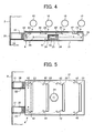
- FIG. 4 is a side view of the optical writing device 4, and FIG. 5 is a plan view of the optical writing device 4.
- the optical writing device 4 of FIG. 4 includes an optical writing unit 41 that emits a laser light beam for writing, the outer case 21 that accommodates the optical writing unit 41, the air supplying device 22 that supplies air into the outer case 21, and the air-intake path 30 through which outside air is taken into the outer case 21 by driving the air supplying device 22.
- Four slit openings 23 are formed in an upper portion of the outer case 21 to pass laser light beams through the slit openings 23, respectively.
- the optical writing unit 41 includes optical members, such as four semiconductor lasers (not shown) that emit laser light beams, the polygon mirror 24 that reflects the laser light beams emitted from the semiconductor lasers, the polygon motor 25 that drives the polygon mirror 24 to rotate, and a plurality of mirrors 26 that reflect the laser light beams reflected from the polygon mirror 24 toward the slit openings 23.
- optical members are disposed at positions where they are exposed to the air supplied into the outer case 21. That is, the semiconductor lasers, the soundproof glasses 34 that surround the polygon mirror 24 and the polygon motor 25, and the mirrors 26 are disposed at positions where they are exposed to the air supplied into the outer case 21. Stated another way, a part of the optical members, such as the polygon mirror 24, and the polygon motor 25, are exposed to the air supplied into the outer case 21 via a transparent cover member, such as the soundproof glasses 34.
- Guide ribs 42 are formed on the inner peripheral surface of the outer case 21 so as to direct the air supplied into the outer case 21 to the slit openings 23 such that the air is blown out from the slit openings 23 substantially equally. Such a problem is prevented by forming the guide ribs 42 that a large amount of air supplied into the outer case 21 is blown out from the slit opening 23 located at the nearest side relative to the air supplying device 22 and less amount of air is blown out from the other slit openings 23. If the amount of air blown out from the slit opening 23 is small, the scattered toner and powder dust floating in the main body 2 of the color printer 1a may enter the outer case 21 through the slit opening 23.
- the air outside of the main body 2 of the color printer 1a is supplied into the outer case 21 through the air-intake path 30 by driving the air supplying device 22 at the time of image formation.
- the outside air contains significantly low amount of scattered toner and powder dust as compared to the air in the main body 2 of the color printer 1a.
- the filter 31 removes the powder dust before the outside air is supplied into the outer case 21.
- clean air can be supplied into the outer case 21, and powder dust can be prevented from entering the outer case 21.
- the air pressure in the outer case 21 increases.
- the air supplied into the outer case 21 flows as indicated by the arrows in FIGS. 4 and 5 and discharges from the outer case 21 while being blown out from the slit openings 23.
- the air supplied into the outer case 21 is directed to the slit openings 23 by the guide ribs 42, and is blown out from the slit openings 23 substantially equally.
- the scattered toner and powder dust floating in the main body 2 of the color printer 1a are prevented from entering the outer case 21 through the slit openings 23.
- the scattered toner and powder dust are prevented from adhering to the semiconductor lasers, the sound-proof glasses 34 surrounding the polygon mirror 24 and the polygon motor 25, and the mirrors 26 all of which form the optical writing unit 41.
- the deterioration of image quality caused by scattered toner and powder dust adhered to the semiconductor lasers, the sound-proof glasses 34 surrounding the polygon mirror 24 and the polygon motor 25, and the mirrors 26 can be minimized or avoided.
- the configuration of the optical writing device 4 is substantially similar to that of the optical writing device 4 of FIG. 2 except for rise wall portions 51 formed at the upper portion of the outer case 21.
- the rise wall portions 51 stand upward substantially perpendicularly relative to a surface of the upper portion of the outer case 21.
- the slit openings 23 are formed in the rise wall portions 51, respectively.
- the projected area of the slit opening 23 seen from above the slit opening 23 in the vertical direction is substantially zero.
- the scattered toner and powder dust floating in the main body 2 of the color printer 1a are prevented from entering the outer case 21 through the slit openings 23. Accordingly, the scattered toner and powder dust are prevented from adhering to the dust-proof glasses 29 provided in the inner case 27. As a result, the deterioration of image quality caused by scattered toner and powder dust adhered to the dust-proof glasses 29 can be minimized or avoided.
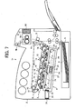
- FIG. 7 is a side view of a color printer 1b according to another embodiment of the present invention.
- the configuration of the color printer 1b of FIG. 7 is similar to that of the color printer of FIG. 1 except that the color printer 1b of FIG. 7 includes a fan 61 acting as an air exhaust device, and a filter 62 in the main body 2.
- the air outside of the outer case 21 is exhausted from the main body 2 by driving the fan 61.
- the filter 62 collects scattered toner and powder dust contained in the air exhausted from the main body 2.
- the air pressure outside of the outer case 21 in the main body 2 becomes lower than the atmospheric pressure by driving the fan 61 at the time of image formation.
- the air which is supplied into the outer case 21 by driving the air supplying device 22, blows out of the slit openings 23 strongly, and the scattered toner and powder dust floating in the main body 2 are significantly prevented from entering the outer case 21 through the slit openings 23.
- the deterioration of image quality caused by scattered toner and powder dust entered into the outer case 21 can be minimized or avoided.
- the filter 62 collects scattered toner and powder dust floating in the main body 2 by driving the fan 61, scattered toner and powder dust can be prevented from entering the outer case 21 through the slit openings 23.
- FIG. 8 is a side view of a color printer 1b as an example of an image forming apparatus according to an embodiment of the present invention.
- the configuration of the color printer 1b of FIG. 8 is similar to that of the color printer 1 of FIG. 1 except for the optical writing device 4. For this reason, only the configuration of the optical writing device 4 will be described hereinafter.
- FIG. 9 is a side view of the optical writing device 4 according to another embodiment of the present invention.
- the optical writing device 4 includes the optical writing unit 20 that emits a laser light beam for writing, the outer case 21 that accommodates the optical writing unit 20, the air supplying device 22 that supplies air into the outer case 21, and the air-intake path 30 through which outside air is taken into the outer case 21 by driving the air supplying device 22.
- Four slit openings 23a, 23b, 23c, and 23d are formed in the upper surface portion of the outer case 21 to pass laser light beams through the slit openings 23a, 23b, 23c, and 23d, respectively.
- the slit openings 23a, 23b, 23c, and 23d are formed at positions where the slit openings 23a, 23b, 23c, and 23d face the photoreceptors 10 on which toner images of different colors are formed, respectively. Further, the slit openings 23a, 23b, 23c, and 23d are formed parallel to the axial direction of the photoreceptors 10 side by side. The opening areas of the slit openings 23a, 23b, 23c, and 23d are different to each other (described below).
- the optical writing unit 20 includes optical members, such as four semiconductor lasers (not shown) that emit laser light beams, the polygon mirror 24 that reflects the laser light beams emitted from the semiconductor lasers, the polygon motor 25 that drives the polygon mirror 24 to rotate, and the plurality of mirrors 26 that reflect the laser light beams reflected from the polygon mirror 24 toward the slit openings 23a, 23b, 23c, and 23d.
- the inner case 27 accommodates the semiconductor lasers, the polygon mirror 24, the polygon motor 25, and the mirrors 26.
- the four slit openings 28 are formed in the inner case 27 to pass laser light beams being emitted to the slit openings 23a, 23b, 23c, and 23d through the slit openings 28, respectively.
- the slit openings 28 are formed parallel to the axial direction of the photoreceptors 10. Each of the slit openings 28 is closed with the dust-proof glass 29 that allows a laser light beam to transmit it.
- the optical writing unit 20 is detachably attached into the outer case 21 for easy maintenance.
- a lock mechanism (not shown) is provided in the outer case 21 to position and lock the optical writing unit 20.
- the air-intake path 30 is provided to communicate the outside of the main body 2 of the color printer 1c to the inside of the outer case 21.
- the air supplying device 22 is disposed at the position in the outer case 21 where the air-intake path 30 is connected to the outer case 21.
- the outside air is taken into the outer case 21 through the air-intake path 30 by driving the air supplying device 22.
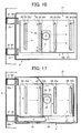
- FIG. 10 is a plan view of the optical writing device 4 of FIG. 9. As illustrated in FIG. 10, two pairs of the air-intake path 30 and the air supplying device 22 are disposed in the vicinity of both end sides of the slit opening 23a in its longitudinal direction, respectively. Referring back to FIG.
- the filter 31 for collecting dust is attached to the end portion of the air-intake path 30 which communicates with the outside of the main body 2.
- the filter 31 eliminates the powder dust in the air supplied into the outer case 21 by driving the air supplying device 22.
- the filter 31 is detachably attached into the air-intake path 30 for easy maintenance.
- the air supplied into the outer case 21 by driving the air supplying device 22 flows in a space formed between the inner peripheral surface of the outer case 21 and the outer peripheral surface of the inner case 27 as indicated by the arrows in FIG. 9. Further, as indicated by the arrows in FIG. 9, the air is discharged from the outer case 21 while being blown out from the slit openings 23a, 23b, 23c, and 23d formed in the outer case 21.
- the opening areas of the slit openings 23a, 23b, 23c, and 23d are different from each other.
- the opening area of the slit opening 23a which is located on the most upstream side in a direction in which the air supplying device 22 supplies air into the outer case 21 (hereafter referred to as an "air supplying direction"), is the smallest as compared to the opening areas of the slit openings 23b, 23c, and 23d.
- the opening areas of the slit openings 23b, 23c, and 23d gradually increase as the positions of the slit openings 23b, 23c, and 23d are away from the air supplying device 22.
- the opening areas of the slit openings 23a, 23b, 23c, and 23d are equal, a large amount of air may be blown out from the slit opening 23a located on the most upstream side in the air supplying direction, and an amount of air blown out from the slit opening 23d located on the downstream side in the air supplying direction may decrease, and the wind speed of the air blown out from the slit opening located on the downstream side in the air supplying direction, may be significantly reduced. If the wind speed of the air blown out from the slit opening is low, the scattered toner and powder dust floating in the main body 2 of the color printer 1c typically enter the outer case 21 through the slit opening.
- the opening areas of the slit openings 23a, 23b, 23c, and 23d are set such that each wind speed of the air blown out from the slit openings 23a, 23b, 23c, and 23d becomes equal to or greater than a predetermined value, such as a one meter/second.
- each width of the slit openings 23a, 23b, 23c, and 23d i.e., the size in the direction in which the slit openings 23a, 23b, 23c, and 23d are disposed side by side
- each length of the slit openings 23a, 23b, 23c, and 23d i.e., the size in the longitudinal direction of the slit openings 23a, 23b, 23c, and 23d
- the airflow path 33 is formed at an outer peripheral portion of the inner case 27 to cool the polygon motor 25.
- the area in which the polygon motor 25 and the polygon mirror 24 are disposed in the inner case 27 is separated by the soundproof glasses 34 that allow a laser light beam to transmit the soundproof glasses 34.
- the airflow path 33 is formed by denting the upper portion of the inner case 27 above the area, and is located adjacent to the polygon motor 25.
- the airflow path 33 is formed at the position where the air supplied into the outer case 21 by the air supplying device 22 flows toward the slit openings 23c and 23d.
- a part of the airflow path 33 adjacent to the polygon motor 25 is formed from the metal plate 35 having high thermal conductivity. Therefore, the heat generated from the polygon motor 25 is preferably released from the metal plate 35 into the air passing through the airflow path 33, so that the polygon motor 25 is efficiently cooled.
- the air outside of the main body 2 of the color printer 1a is supplied into the outer case 21 through the air-intake path 30 by driving the air supplying device 22 at the time of image formation.
- the outside air contains significantly low amount of scattered toner and powder dust as compared to the air in the main body 2 of the color printer 1c.
- the filter 31 removes the powder dust before the outside air is supplied into the outer case 21.
- clean air can be supplied into the outer case 21, and powder dust can be prevented from entering the outer case 21.
- each wind speed of the air blown out from the slit openings 23a, 23b, 23c, and 23d becomes equal to or greater than a predetermined value.
- the scattered toner and powder dust floating in the main body 2 of the color printer 1c are prevented from entering the outer case 21 through the slit openings 23a, 23b, 23c, and 23d. Accordingly, the scattered toner and powder dust are prevented from adhering to the dust-proof glasses 29 provided in the inner case 27. As a result, the deterioration of image quality caused by scattered toner and powder dust adhered to the dust-proof glasses 29 can be minimized or avoided.
- two air supplying devices 22 are provided in the optical writing device 4.
- the number of the air supplying device 22 may be one or greater than two.
- the opening areas of the slit openings 23a, 23b, 23c, and 23d are different from each other.
- the slit openings 23a, 23b, 23c, and 23d may be formed to have at least two different sizes of opening areas such that each wind speed of air blown out from the slit openings 23a, 23b, 23c, and 23d becomes a predetermined value or greater.
- the opening areas of the slit openings 23a and 23b located on the upstream side in the air supplying direction may be set to be equal, and the opening areas of the slit openings 23c and 23d located on the downstream side in the air supplying direction may be set to be equal.
- the opening areas of the slit openings 23c and 23d may be greater than the opening areas of the slit openings 23a and 23b.
- the opening areas of the slit openings 23a, 23b, and 23c located on the upstream side in the air supplying direction may be set to be equal, and the opening area of the slit opening 23d located on the downstream side in the air supplying direction may be greater than the opening areas of the slit openings 23a, 23b, and 23c.
- the opening areas of the slit openings 23b, 23c, and 23d located on the downstream side in the air supplying direction may be set to be equal, and the opening area of the slit opening 23a located on the upstream side in the air supplying direction may be smaller than the opening areas of the slit openings 23b, 23c, and 23d.
- the optical writing device 4 of FIG. 11 includes two air supplying devices 22a and 22b. It is configured that the air supplied from the air supplying device 22a into the outer case 21 is blown out from the two slit openings 23a and 23b, and the air supplied from the air supplying device 22b into the outer case 21 is blown out from the two slit openings 23c and 23d.
- a plate-shaped air supplying guide 71 is disposed in the optical writing device 4 such that the space between the inner surface of the outer case 21 and the outer surface of the inner case 27 is partitioned with the air supplying guide 71.
- the air supplying guide 71 directs the air supplied from the air supplying device 22a to the slit openings 23a and 23b.
- air supplying guides 72 and 73 are provided in the optical writing device 4 to direct the air supplied from the air supplying device 22b to the slit openings 23c and 23d.
- the air supplying guide 72 is a duct-shaped member
- the air supplying guide 73 is a plate-shaped member disposed such that the space between the inner surface of the outer case 21 and the outer surface of the inner case 27 is partitioned with the air supplying guide 73.
- the air supplied from the air supplying device 22a is blown out from the slit openings 23a and 23b.
- the opening area of the slit opening 23a disposed on the upstream side in the air supplying direction relative to the slit opening 23b is formed relatively small, and the opening area of the slit opening 23b disposed on the downstream side in the air supplying direction relative to the slit opening 23a is formed relatively great.
- the opening areas of the slit openings 23a and 23b are adjusted such that each wind speed of air blown out from the slit openings 23a and 23b becomes a predetermined value or greater.
- the opening areas of the slit openings 23a and 23b may be equal so long as each wind speed of air blown out from the slit openings 23a and 23b becomes a predetermined value or greater.
- the air supplied from the air supplying device 22b is blown out from the slit openings 23c and 23d.
- the opening area of the slit opening 23c disposed on the upstream side in the air supplying direction relative to the slit opening 23d is formed relatively small, and the opening area of the slit opening 23d disposed on the downstream side in the air supplying direction relative to the slit opening 23c is formed relatively great.
- the opening areas of the slit openings 23c and 23d are adjusted such that each wind speed of air blown out from the slit openings 23c and 23d becomes a predetermined value or greater.
- the opening areas of the slit openings 23c and 23d may be equal so long as each wind speed of air blown out from the slit openings 23c and 23d becomes a predetermined value or greater.
- the air supplied from the air supplying device 22a can be blown out from the slit openings 23a and 23b with accuracy, and the air supplied from the air supplying device 22b can be blown out from the slit openings 23c and 23d with accuracy.
- each wind speed of air blown out from the slit openings 23a, 23b, 23c, and 23d can be maintained at a predetermined value or greater with accuracy.
- an air supplying device need not be provided to each of the slit openings 23a, 23b, 23c, and 23d, that is, the number of air supplying devices is less than the number of the slit openings 23a, 23b, 23c, and 23d, the cost of the optical writing device can be reduced.
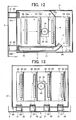
- the optical writing device 4 of FIG. 12 includes two air supplying devices 22a and 22b that supply air into the outer case 21. It is configured that the air supplied from the air supplying device 22a into the outer case 21 is blown out from the three slit openings 23a, 23b, and 23c, and the air supplied from the air supplying device 22b into the outer case 21 is blown out from the slit opening 23d.
- a plate-shaped air supplying guide 74 is disposed in the optical writing device 4 such that the space between the inner surface of the outer case 21 and the outer surface of the inner case 27 is partitioned with the air supplying guide 74.
- the air supplying guide 74 directs the air supplied from the air supplying device 22a to the slit openings 23a, 23b and 23c.
- air supplying guides 75 and 76 are provided in the optical writing device 4 to direct the air supplied from the air supplying device 22b to the slit opening 23d.
- the air supplying guide 75 is a duct-shaped member, and the air supplying guide 76 is a plate-shaped member disposed such that the space between the inner surface of the outer case 21 and the outer surface of the inner case 27 is partitioned with the air supplying guide 76.
- the air supplied from the air supplying device 22a is blown out from the slit openings 23a, 23b, and 23c.
- the opening area of the slit opening 23a disposed on the upstream side in the air supplying direction relative to the slit openings 23b and 23c is formed relatively small, and the opening area of the slit opening 23b is formed greater than that of the slit opening 23a, and the opening area of the slit opening 23c is formed greater than that of the slit opening 23b.
- the opening areas of the slit openings 23a, 23b and 23c are adjusted such that each wind speed of air blown out from the slit openings 23a, 23b and 23c becomes a predetermined value or greater.
- the opening areas of the slit openings 23a, 23b and 23c may be equal so long as each wind speed of air blown out from the slit openings 23a, 23b and 23c becomes a predetermined value or greater.
- the air supplied from the air supplying device 22b is blown out from the slit opening 23d.
- the opening area of the slit opening 23d is formed substantially equal to or greater than that of the slit opening 23c.
- the opening area of the slit opening 23d is adjusted such that the wind speed of air blown out from the slit opening 23d becomes a predetermined value or greater.
- the air supplied from the air supplying device 22a can be blown out from the slit openings 23a, 23b, and 23c with accuracy, and the air supplied from the air supplying device 22b can be blown out from the slit opening 23d with accuracy.
- each wind speed of air blown out from the slit openings 23a, 23b, 23c, and 23d can be maintained at a predetermined value or greater with accuracy.
- an air supplying device need not be provided to each of the slit openings 23a, 23b, 23c, and 23d, that is, the number of air supplying devices is less than the number of the slit openings 23a, 23b, 23c, and 23d, the cost of the optical writing device can be reduced.
- An optical writing device 81 of FIG. 13 includes the optical writing unit 20 that emits a laser light beam for writing, the outer case 21 that accommodates the optical writing unit 20, the air supplying devices 22 that supply air into the outer case 21, and the air-intake paths 30 through which outside air is taken into the outer case 21 by driving the air supplying devices 22.
- each slit opening 82 is formed in the upper surface portion of the outer case 21 to pass laser light beams through the slit openings 82, respectively.
- the slit openings 82 are formed parallel to the axial direction of the photoreceptors 10 side by side.
- Four air supplying devices 22 are provided corresponding to the four slit openings 82, respectively.
- Each air supplying device 22 is disposed at one end side of each of the slit openings 82 in its longitudinal direction.
- a plurality of air supplying guides 83 are provided in the outer case 21.
- the air supplying guides 83 direct air supplied from the air supplying devices 22 to the slit openings 82, respectively.
- Each of the air supplying guides 83 is formed from a plate member and a space between the inner surface of the outer case 21 and the outer surface of the inner case 27 is partitioned with the air supplying guides 83.
- each of the slit openings 82 located at the position most close to the air supplying device 22 is formed small.
- the width of each of the slit openings 82 gradually increases as the position of each of the slit openings 82 is away from the air supplying device 22.
- the air outside of the main body 2 of the color printer 1c is supplied into the outer case 21 through the air-intake path 30 by driving the air supplying devices 22 at the time of image formation.
- the air supplied into the outer case 21 flows as indicated by the arrows in FIG. 13 and discharges from the outer case 21 while being blown out from the slit openings 82.
- air is blown out from each of the slit openings 82 at a predetermined wind speed or more, thereby preventing scattered toner and powder dust floating in the main body 2 of the color printer 1c from entering the outer case 21 through the slit openings 82.
- the air supplying guides 83 are provided and function as partition members that separate the slit openings 82 from each other, each wind speed of air blown out from the slit openings 82 can be maintained at a predetermined value or greater with accuracy.
- each of the slit openings 82 gradually increases as the position of each of the slit openings 82 is away from the air supplying device 22.
- occurrences of the following problems are minimized or avoided, for example: (1) a large amount of air blows out from the portion of the slit opening 82 located adjacent to the air supplying device 22, and an amount of air blown out from the portion of the slit opening 82 located at the position away from the air supplying device 22 significantly decreases; and (2) the wind speed of air blown out from the portion of the slit opening 82 located adjacent to the air supplying device 22 increases, and the wind speed of air blown out from the portion of the slit opening 82 located at the position away from the air supplying device 22 decreases. If the wind speed of air blown out from the slit opening 82 is low, the scattered toner and powder dust floating in the main body 2 of the color printer 1c may easily enter the outer case 21.
- each wind speed of air blown out from the slit openings 82 in the entire area in the longitudinal direction of the slit openings 82 can be maintained at a predetermined value or greater with accuracy. As a result, scattered toner and powder dust can be prevented from entering the outer case 21 through the slit openings 82.
- FIG. 14 is a side view of a color printer 1d according to another embodiment of the present invention.
- the configuration of the color printer 1d of FIG. 14 is similar to that of the color printer 1c of FIG. 8 except that the color printer 1d of FIG. 14 includes the fan 61 acting as an air exhaust device, and the filter 62 in the main body 2.
- the air outside of the outer case 21 is exhausted from the main body 2 by driving the fan 61.
- the filter 62 collects scattered toner and powder dust contained in the air exhausted from the main body 2.
- the air pressure outside of the outer case 21 in the main body 2 becomes lower than the atmospheric pressure by driving the fan 61 at the time of image formation.
- the air supplied into the outer case 21 blows out from the slit openings 23a, 23b, 23c, and 23d at a high wind speed, and thereby scattered toner and powder dust are significantly prevented from entering the outer case 21 through the slit openings 23a, 23b, 23c, and 23d.
- the deterioration of image quality caused by scattered toner and powder dust entered into the outer case 21 can be minimized or avoided.
- the filter 62 collects scattered toner and powder dust floating in the main body 2 by driving the fan 61, scattered toner and powder dust can be prevented from entering the outer case 21 through the slit openings 23a, 23b, 23c, and 23d.
- the air supplying device 22 may employ a fan, a bellows pump, and a moineau pump.
- a fan, a bellows pump, and a moineau pump air can be supplied into the outer case 21 with a compact configuration.
- a bellows expansion element is expanded and contracted by driving a motor. Air is sucked in and exhausted from the bellows expansion element by expanding and contracting the bellows expansion element. The air exhausted from the bellows expansion element is supplied into the outer case 21.
- a rotor is rotated in a cylindrical element by driving a motor. Air is sucked in from one end side of the cylindrical element and is exhausted from another end side of the cylindrical element by rotating the rotor. The air exhausted from the cylindrical element is supplied into the outer case 21.
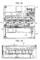
- FIG. 15 is a schematic cross sectional view of a color printer as an example of an image forming apparatus.
- FIG. 16 is a schematic cross sectional view of an image forming section of the color printer of FIG. 15.
- the color printer of FIG. 15 includes an image forming section 101 as a main body.
- the image forming section 101 includes four photoconductor units 102 used for forming toner images of different colors, a transfer device 103, and an optical writing device 104.
- Each of the photoconductor units 102 includes a photoreceptor 105 acting as an image carrier configured to carry a latent image.
- the image forming section 101 further includes developing units 106 provided to the photoconductor units 102, respectively, and an intermediate transfer belt 107.
- the color printer of FIG. 15 further includes a sheet feeding section 108 having a sheet feeding cassette 109.
- the color printer of FIG. 15 further includes a fixing and sheet discharging section 110 having a fixing device 111 and a sheet discharging device 112.
- a color image is formed and transferred onto a sheet fed from the sheet feeding cassette 109 in the image forming section 101.
- the transferred color image is fixed onto the sheet by the fixing device 111.
- the sheet having the color image is discharged from the color printer by the sheet discharging device 112. Because a configuration and operation of a color image forming apparatus for forming color images are well known, the description is omitted here.
- the optical writing device 104 is disposed below the photoconductors 105 in the photoconductor units 102, and a partition member 115 is interposed between the photoconductor units 102 and the optical writing device 104.
- the dotted lines denoted by a reference character "L" indicate a light path of a laser light beam emitted from the optical writing device 104. For the sake of simplification of the description, it will be referred to as a laser light beam "L”, hereinafter.
- FIG. 17A is a cross sectional view of the partition member 115
- FIG. 17B is a perspective view of the partition member 115 of FIG. 17A.
- the partition member 115 is formed by bending a plate member repeatedly at a substantially right angle, and has a convex and concave cross section.
- the partition member 115 includes an upper stepped surface 116, a lower stepped surface 119, and a pendent surface 117.
- the upper stepped surface 116 is located at the position between the two photoreceptor units 102, that is, below the developing unit 106.
- the pendent surface 117 extends downwardly from the upper stepped surface 116 to the lower stepped surface 119.
- the position of the pendent surface 117 corresponds to the position of the photoreceptor 105 to which a laser light beam "L" is emitted from optical members 113, such as semiconductor lasers and a polygon mirror, of the optical writing device 104. Further, a slit opening 118 is formed in the pendent surface 117 such that the slit opening 118 elongates along a scanning direction of the optical writing device 104.
- the optical writing device 104 emits the laser light beam "L” from the optical members 113 toward the surface of the photoreceptor 105 through the slit opening 118 to form a latent image thereon.
- the lower stepped surface 119 is located below the photoreceptor unit 102.
- the reason for forming the slit opening 118 in the pendent surface 117 which extends from the upper stepped surface 116 along the up and down direction in the color printer is that the projected area of the slit opening 118 in a falling direction of toner and powder dust from the developing unit 106 and the photoreceptor 105 becomes minimum, in consideration of the possibility that toner and powder dust may fall from the developing unit 106 and the photoreceptor 105 when a latent image is written on the surface of the photoreceptor 105 with the laser light beam "L" emitted from lower side of the photoreceptor 105.
- the slit opening 118 in the pendent surface 117 in a vertical direction the toner and powder dust falling from the developing unit 106 and the photoreceptor 105 are minimized or prevented from entering the slit opening 118.
- the lower edge of the slit opening 118 is located at a slightly upper side relative to the lower stepped surface 119 in the vertical direction. That is, a wall part 117a of the pendent surface 117 exists between the lower edge of the slit opening 118 and the lower stepped surface 119.
- the wall part 117a of the pendent surface 117 prevents scattered toner X deposited on the lower stepped surface 119 from entering the inner side of the upper stepped surface 116 (i.e., toward the optical writing device 104) through the slit opening 118.
- FIG. 18A is a perspective view of a shutter mechanism configured to open and close the slit opening 118
- FIG. 18B is a top view of the shutter mechanism of FIG. 18A.
- the shutter mechanism of the present embodiment includes a shutter member 120 having an L-shaped cross section and including a vertical portion 120b and a lateral portion 120a, a biasing member 121 such as a spring, that biases the shutter member 120 toward the slit opening 118, and stepped screws 122 used for attaching the lateral portion 120a of the shutter member 120 onto the lower stepped surface 119 of the partition member 115.
- a pair of groove openings 123 are formed slantwise in the lateral portion 120a of the shutter member 120 provided parallel to the lower stepped surface 119.
- the shutter member 120 is configured to contact and separate with and from the pendent surface 117 including the slit opening 118 by moving in parallel to and slantwise relative to the pendent surface 117 in the direction indicated by the arrows in FIGS. 18A and 18B.
- the biasing member 121 always biases the shutter member 120 toward a front side in FIGS. 18A and 18B. Therefore, in the default position, the shutter member 120 closes the slit opening 118.
- the color printer of the present embodiment further includes a cover plate 150 disposed over the front side of the color printer to cover the image forming section 101 including the photoconductor units 102, the transfer device 103, the optical writing device 104, the developing units 106, and the intermediate transfer belt 107.
- the cover plate 150 is configured to cover and uncover the image forming section 101 by closing and opening the cover plate 150.
- a plurality of protruding members 160 such as ribs, are provided on the inner side of the cover plate 150. Referring to FIG.
- the protruding member 160 contacts and presses the biasing member 121 from the front side to the rear side in FIG. 18B, and thereby the shutter member 120 moves backward in a direction away from the slit opening 118.
- the slit opening 118 opens.
- the protruding member 160 moves from the rear side to the front side in FIG. 18B, and thereby the shutter member 120 moves forward in a direction approaching and contacting the slit opening 118.
- the slit opening 118 is closed with the shutter member 120.
- the cover plate 150 and the protruding member 160 act as a drive device configured to drive the shutter mechanism to move to open and close the slit opening 118.
- the shutter member 120 closes the slit opening 118. Accordingly, the scattered toner and powder dust falling from the photoreceptor 105 can be prevented from entering the slit opening 118.
- FIG. 19 is a cross sectional view of the partition member 115 and the shutter member 120 according to another embodiment of the present invention.
- a plurality of convex portions 124 are provided on the lower surface of the shutter member 120.
- the convex portions 124 slidably contact the lower stepped surface 119 of the partition member 115.
- the convex portions 124 minimize the contact of the lower surface of the shutter member 120 with scattered toner deposited on the lower stepped surface 119. Thereby, the scattered toner less moves on the lower stepped surface 119, preventing the scattered toner from entering the slit opening 118.
- the convex portions 124 need to be provided at at least three positions. In the case of forming the shutter member 120 by a plate metal processing, the convex portions 124 can be easily formed by a half blanking processing.
- FIG. 20 is a cross sectional view of the partition member 115 and the shutter member 120 according to another embodiment of the present invention.
- an elastic member 125 is attached onto a surface of the vertical portion 120b of the shutter member 120 facing the slit opening 118.
- the shutter member 120 closes the slit opening 118, the slit opening 118 can be sealed with the elastic member 125. Accordingly, scattered toner is surely prevented from entering the slit opening 118.
- the shutter member 120 may be integrally formed from resin and an elastomer. In this case, material and labor costs can be reduced as compared to a manual attachment of the elastic member 125 to the shutter member 120.
- FIG. 21 is a top view of the shutter mechanism according to another embodiment of the present invention.
- the shutter member 120 includes front and rear cam surfaces 126 on the front and rear sides in FIG. 21, respectively.
- a side plate 127 of the color printer which is located on the rear side of the partition member 115 slidably contacts the rear cam surface 126.
- the biasing member 121 is interposed slantwise between the shutter member 120 and the lower stepped surface 119 of the partition member 115.
- the protruding member 160 contacts and presses the shutter member 120 from the front side to the rear side in FIG.
- the shutter member 120 moves backward in a direction away from the slit opening 118 by sliding the rear cam surface 126 relative to the side plate 127.
- the slit opening 118 opens.
- the protruding member 160 moves from the rear side to the front side in FIG. 21, and thereby the shutter member 120 moves forward in a direction approaching and contacting the slit opening 118 by sliding the rear cam surface 126 relative to the side plate 127.
- the slit opening 118 is closed with the shutter member 120.
- the shutter member 120 can contact and separate with and from the slit opening 118 by using a simple configuration, such as the rear cam surface 126 and the side plate 127, the cost of the color printer can be reduced as compared to the configuration using the stepped screws 122.
- the front cam surface 126 instead of slidably contacting the rear cam surface 126 with the side plate 127, the front cam surface 126 may slidably contact a side plate 128 of the color printer. Further, both the front and rear cam surfaces 126 may slidably contact the side plates 128 and 127, respectively.
- FIG. 22 is a perspective view of the shutter mechanism according to another embodiment of the present invention.
- the shutter mechanism of FIG. 22 includes a plated-shaped shutter member 130, and a pair of link members 131 attached to the both end portions of the shutter member 130, respectively, to support the shutter member 130.
- one end portion of the link member 131 is attached to one end portion of the shutter member 130, and the other end portion of the link member 131 is attached onto the pendent surface 117.
- the other end portion of the link member 131 may be attached to a member in the image forming section 101 of the color printer.
- the shutter mechanism further includes a biasing device (not shown), such as a spring, that always biases the shutter member 130 toward the slit opening 118.
- the shutter member 130 closes the slit opening 118.
- the protruding member 160 contacts and presses the biasing member of the shutter mechanism of FIG. 22, and thereby the shutter member 130 rotates upward in parallel to the slit opening 118 in a direction away from the slit opening 118.
- the slit opening 118 opens.
- the protruding member 160 moves from the rear side to the front side in FIG. 22, and thereby the shutter member 130 rotates downward in parallel to the slit opening 118 in a direction approaching and contacting the slit opening 118.
- the slit opening 118 is closed with the shutter member 130.
- This configuration is effective especially when there is no enough space for disposing a shutter member on the lower stepped surface 119 of the partition member 115.
- FIG. 23 is a cross sectional view of a lock mechanism for a shutter mechanism according to an embodiment of the present invention.
- the color printer of the present embodiment includes a lock mechanism 140 at the rear side of the image forming section 101.
- the lock mechanism 140 is configured to lock the shutter member 120 or 130 so that the slit opening 118 is kept closed.
- the shutter member 120 or 130 When the photoconductor unit 102 is inserted into the image forming section 101, the shutter member 120 or 130 is unlocked so that the shutter member 120 or 130 can move and the slit opening 118 is opened.
- the slit opening 118 With the above-described lock mechanism 140, the slit opening 118 is prevented from being opened by erroneous operations of a user. Accordingly, toner and powder dust are prevented from entering the slit opening 118.
- the lock mechanism 140 may be used for all the shutter mechanisms of FIGS. 18A through 22.
- the shutter member 120 or 130 is configured to open and close the slit opening 118 by closing and opening the cover plate 150 by pressing and releasing the bias member with the protruding member 160.
- an end portion of the shutter member 120 or 130 may extend toward the cover plate 150.
- the shutter member 120 or 130 may be configured to open and close the slit opening 118 by closing and opening the cover plate 150 by pressing and releasing the extended end portion of the shutter member 120 or 130.
- any other configuration of the drive device may be employed so long as the shutter member 120 or 130 can be moved backward and forward to open and close the slit opening 118.
- the color printer may include an outer cover plate 150a and an inner cover plate 150b as illustrated in FIGS. 24A and 24B.
- FIG. 24A is a perspective view of a part of the color printer when the outer cover plate 150a is opened and the inner cover plate 150b is closed.
- FIG. 24B is a perspective view of a part of the color printer when the outer cover plate 150a and the inner cover plate 150b are opened.
- the outer cover plate 150a is disposed over the front side of the color printer to cover the image forming section 101 including the photoconductor units 102, the transfer device 103, the optical writing device 104, the developing units 106, and the intermediate transfer belt 107.
- the inner cover plate 150b is also disposed over the front side of the color printer to cover a part of the image forming section 101, such as the photoconductor units 102, the transfer device 103, the developing units 106, and the intermediate transfer belt 107.
- a plurality of protruding members 160a are provided on the inner side of the outer cover plate 150a as illustrated in FIG. 24A.
- the slit openings 118 are closed with the shutter members 120 or 130.
- the inner cover plate 150b is opened for check, repair, or replacement of the photoconductor units 102 and the developing units 10b.
- the outer cover plate 150a is closed after closing the inner cover plate 150b, the protruding members 160a contact and press the biasing members from the front side to the rear side in FIG. 24A, and thereby the shutter members 120 or 130 move backward in a direction away from the slit openings 118.
- the slit openings 118 open.
- the protruding members 160a may be provided on the inner side of the inner cover plate 150b instead of the outer cover plate 150a. However, scattered toner and powder dust can be further prevented from entering the slit openings 118 by closing the slit openings 118 with the shutter members 120 or 130 immediately upon opening the outer cover plate 150a with the protruding members 160a.
- the photoconductor unit 102 and the developing unit 106 are configured to be separately replaced with new ones due to the difference of their useful lifetime.
- the photoconductor unit 102 including a charging roller 170, etc. and the developing unit 106, may be integrally accommodated in a process cartridge 180 for easy maintenance and operability as illustrated in FIG. 25.
- scattered toner and powder dust are minimized or avoided from entering the optical writing device 104 through the slit openings 118. Therefore, an occurrence of a white streak image, which is caused by toner and powder dust interrupting the emission of laser light beams toward the photoreceptors 105, can be prevented.
- the present invention has been described with respect to a color printer as an example of an image forming apparatus. However, the present invention may be applied to other image forming apparatuses, such as a copying machine, a facsimile machine, etc. or a multi-functional image forming apparatus.
- the present invention may be applied to an image forming apparatus including one photoreceptor on which toner images of different colors are sequentially formed.
Landscapes
- Physics & Mathematics (AREA)
- General Physics & Mathematics (AREA)
- Control Or Security For Electrophotography (AREA)
- Laser Beam Printer (AREA)
- Electrophotography Configuration And Component (AREA)
- Accessory Devices And Overall Control Thereof (AREA)
- Exposure Or Original Feeding In Electrophotography (AREA)
Abstract
Description
The
Claims (43)
- An optical writing device comprising:an optical writing unit configured to emit a laser light beam;an outer case configured to accommodate the optical writing unit, the outer case including at least one first opening through which the laser light beam passes; andat least one air supplying device configured to supply air into the outer case.
- The optical writing device according to claim 1, wherein the optical writing unit comprises:optical members;an inner case configured to accommodate the optical members, the inner case including at least one second opening through which the laser light beam emitted toward the at least one first opening passes; anda dust-proof glass configured to close the at least one second opening, the dust-proof glass allowing the laser light beam to transmit the dust-proof glass.
- The optical writing device according to claim 1,
wherein the optical writing unit comprises optical members disposed at positions where the optical members are exposed to the air supplied into the outer case. - The optical writing device according to claim 2, wherein the optical writing unit is detachably attached into the outer case.
- The optical writing device according to claim 2,
wherein the at least one first opening comprises a plurality of first openings, and
wherein the optical writing device further comprises first guide ribs formed at an outer peripheral portion of the inner case so as to direct the air supplied into the outer case to the plurality of first openings such that the air is blown out from the plurality of first openings substantially equally. - The optical writing device according to claim 3,
wherein the at least one first opening comprises a plurality of first openings, and
wherein the optical writing device further comprises second guide ribs formed on an inner peripheral surface of the outer case so as to direct the air supplied into the outer case to the plurality of first openings such that the air is blown out from the plurality of first openings substantially equally. - The optical writing device according to claim 1,
wherein the at least one first opening is formed in an upper portion of the outer case in a vertical direction when the optical writing device is attached into an image forming apparatus. - The optical writing device according to claim 7,
wherein the outer case comprises a rise wall portion at the upper portion of the outer case, which stands upward relative to a surface of the upper portion of the outer case, and the at least one first opening is formed in the rise wall portion. - The optical writing device according to claim 1,
wherein the at least one first opening comprises a plurality of first openings, and the plurality of first openings are formed to have at least two different sizes of opening areas such that each wind speed of air which is supplied into the outer case by the at least one air supplying device and blown out from the plurality of first openings becomes a predetermined value or greater. - The optical writing device according to claim 9,
wherein the at least one air supplying device comprises a plurality of air supplying devices, and the air supplied from one of the plurality of air supplying devices is blown out from at least two first openings of the plurality of first openings. - The optical writing device according to claim 10,
wherein an opening area of one first opening of the at least two first openings located on a downstream side in an air supplying direction in which the at least one air supplying device supplies air into the outer case, is one of equal to and greater than an opening area of another first opening of the at least two first openings located on an upstream side in the air supplying direction. - The optical writing device according to claim 9, further comprises at least one air supplying guide configured to direct the air supplied into the outer case to the plurality of first openings.
- The optical writing device according to claim 9, wherein the at least one air supplying device comprises a plurality of air supplying devices which correspond to the plurality of first openings, respectively, and the plurality of air supplying devices supply air into the outer case such that each wind speed of air blown out from the plurality of first openings becomes a predetermined value or greater.
- The optical writing device according to claim 13,
wherein the plurality of air supplying devices are disposed on one end side of the plurality of first openings in a longitudinal direction of the first openings, respectively, and
wherein the optical writing device further comprises a plurality of air supplying guides in the outer case, which are configured to direct the air supplied into the outer case to the plurality of first openings, respectively. - The optical writing device according to claim 14, wherein a width of each of the plurality of first openings gradually increases as a position of each of the plurality of first openings is away from each of the plurality of air supplying devices.
- The optical writing device according to claim 2,
wherein the optical members comprise a polygon mirror, and a polygon motor that drives the polygon mirror to rotate, and
wherein an airflow path is formed at an outer peripheral portion of the inner case so as to pass the air supplied into the outer case over a position adjacent to the polygon motor. - The optical writing device according to claim 16, wherein a part of the airflow path adjacent to the polygon motor is formed from a metal plate having high thermal conductivity.
- The optical writing device according to claim 1, further comprising at least one air-intake path through which outside air is taken into the outer case by driving the at least one air supplying device, and wherein one end of the at least one air-intake path is connected to the outer case, and another end communicates with the outside of an image forming apparatus into which the optical writing device is attached.
- The optical writing device according to claim 18, wherein a filter is provided in the air-intake path.
- The optical writing device according to claim 19, wherein the filter is detachably attached into the air-intake path.
- The optical writing device according to claim 1, wherein the at least one air supplying device comprises a fan.
- The optical writing device according to claim 1, wherein the at least one air supplying device comprises a bellows pump.
- The optical writing device according to claim 1, wherein the at least one air supplying device comprises a moineau pump.
- An image forming apparatus comprising:an image forming device which comprises an image carrier and is configured to form a toner image on the image carrier by an electrophotography process; andan optical writing device configured to form an electrophotographic latent image on the image carrier, the optical writing device comprising the features of at least one of claims 1 to 23.
- The image forming apparatus according to claim 24, further comprising an air exhaust device configured to discharge air outside of the outer case from the image forming apparatus.
- The image forming apparatus according to claim 25, wherein the air exhaust device comprises a fan.
- The image forming apparatus according to one of claims 24 to 26, wherein the image forming device comprises a process cartridge detachably attached to the image forming apparatus.
- An image forming apparatus comprising:at least one image carrier configured to carry a latent image thereon;an optical writing device configured to emit a laser light beam toward the at least one image carrier so as to form a latent image on the at least one image carrier, the optical writing device being disposed below the at least one image carrier;a partition member interposed between the at least one image carrier and the optical writing device, the partition member comprising an opening elongating along a scanning direction of the optical writing device, and the laser light beam being emitted from the optical writing device toward the at least one image carrier through the opening; anda shutter mechanism comprising a shutter member so as to open and close the opening.
- The image forming apparatus according to claim 28, further comprising a drive device configured to drive the shutter mechanism to move the shutter member to open and close the opening.
- The image forming apparatus according to claim 29, wherein the shutter member has an L-shaped cross section, and the shutter mechanism is configured to contact and separate the shutter member with and from a surface of the partition member having the opening by moving the shutter member in parallel and slantwise relative to the surface of the partition member having the opening in cooperation with the drive device.
- The image forming apparatus according to claim 28, wherein the partition member comprises an upper stepped surface, a lower stepped surface, and a pendent surface, the lower stepped surface is located below the at least one image carrier and is lower than the upper stepped surface, and the pendent surface extends downwardly from the upper stepped surface to the lower stepped surface, and includes the opening.
- The image forming apparatus according to claim 31, wherein a lower end of the shutter member movably contacts the lower stepped surface, and a lower edge of the opening is located at an upper side relative to the lower stepped surface in a vertical direction.
- The image forming apparatus according to claim 31, wherein the shutter member comprises a convex portion that slidably contacts the lower stepped surface.
- The image forming apparatus according to one of claims 28 to 33, wherein the shutter member comprises an elastomer on a surface of the shutter member facing the opening.
- The image forming apparatus according to claim 34, wherein the shutter member is integrally formed from resin and an elastomer.
- The image forming apparatus according to claim 29, wherein the shutter member comprises a cam surface brought into sliding contact with a member of a main body of the image forming apparatus, and the drive device is configured to drive the shutter mechanism to move the shutter member by sliding the cam surface relative to the member of the main body of the image forming apparatus.
- The image forming apparatus according to claim 36, wherein the member of the main body of the image forming apparatus comprises a side plate located adjacent to the partition member.
- The image forming apparatus according to claim 37, wherein the shutter mechanism further comprises a biasing device interposed between the partition member and the shutter member to bias the shutter member toward the opening.
- The image forming apparatus according to claim 29, wherein the shutter mechanism further comprises a link member configured to movably support the shutter member, one end of the link member is attached to one end of the shutter member and another end of the link member is attached to one of the partition member and a member of a main body of the image forming apparatus, and the drive device is configured to drive the shutter mechanism to move the link member and the shutter member.
- The image forming apparatus according to claim 29, further comprising a lock mechanism configured to lock the shutter member so that the opening is kept closed during a period when the at least one image carrier is removed from the image forming apparatus.
- The image forming apparatus according to claim 29, further comprising a cover configured to cover a main body of the image forming apparatus, and wherein the drive device comprises the cover, and the shutter member is moved by opening and closing the cover.
- The image forming apparatus according to claim 41, wherein the cover is disposed at a most outer side relative to the main body.
- The image forming apparatus according to one of claims 28 to 42, further comprising a process cartridge comprising the at least one image carrier.
Priority Applications (1)
| Application Number | Priority Date | Filing Date | Title |
|---|---|---|---|
| EP05005233A EP1538001B1 (en) | 2003-09-18 | 2004-09-15 | Preventing scattered toner and powder dust from entering the optical writing device |
Applications Claiming Priority (6)
| Application Number | Priority Date | Filing Date | Title |
|---|---|---|---|
| JP2003326445 | 2003-09-18 | ||
| JP2003325941 | 2003-09-18 | ||
| JP2003326445 | 2003-09-18 | ||
| JP2003325941A JP4330408B2 (en) | 2003-09-18 | 2003-09-18 | Image forming apparatus |
| JP2003370582 | 2003-10-30 | ||
| JP2003370582A JP2005134635A (en) | 2003-10-30 | 2003-10-30 | Optical writing apparatus and image forming apparatus |
Related Child Applications (2)
| Application Number | Title | Priority Date | Filing Date |
|---|---|---|---|
| EP05005233A Division EP1538001B1 (en) | 2003-09-18 | 2004-09-15 | Preventing scattered toner and powder dust from entering the optical writing device |
| EP05005233.1 Division-Into | 2005-03-10 |
Publications (3)
| Publication Number | Publication Date |
|---|---|
| EP1516738A2 true EP1516738A2 (en) | 2005-03-23 |
| EP1516738A3 EP1516738A3 (en) | 2005-06-22 |
| EP1516738B1 EP1516738B1 (en) | 2007-05-23 |
Family
ID=34198766
Family Applications (2)
| Application Number | Title | Priority Date | Filing Date |
|---|---|---|---|
| EP04021915A Expired - Lifetime EP1516738B1 (en) | 2003-09-18 | 2004-09-15 | Preventing scattered toner and powder dust from entering the optical writing device |
| EP05005233A Expired - Lifetime EP1538001B1 (en) | 2003-09-18 | 2004-09-15 | Preventing scattered toner and powder dust from entering the optical writing device |
Family Applications After (1)
| Application Number | Title | Priority Date | Filing Date |
|---|---|---|---|
| EP05005233A Expired - Lifetime EP1538001B1 (en) | 2003-09-18 | 2004-09-15 | Preventing scattered toner and powder dust from entering the optical writing device |
Country Status (5)
| Country | Link |
|---|---|
| US (1) | US7705871B2 (en) |
| EP (2) | EP1516738B1 (en) |
| CN (1) | CN100378587C (en) |
| DE (2) | DE602004006570T2 (en) |
| ES (2) | ES2285324T3 (en) |
Families Citing this family (16)
| Publication number | Priority date | Publication date | Assignee | Title |
|---|---|---|---|---|
| JP4737603B2 (en) | 2004-10-20 | 2011-08-03 | 株式会社リコー | Image forming apparatus |
| US7526223B2 (en) * | 2005-05-10 | 2009-04-28 | Ricoh Company, Ltd. | Heat exhausting structure and image forming apparatus |
| US7872664B2 (en) | 2005-09-26 | 2011-01-18 | Ricoh Company, Limited | Optical scanning device including shutter member that closes or opens an emission window and image forming apparatus including the optical scanning device |
| JP4846317B2 (en) * | 2005-09-26 | 2011-12-28 | 株式会社リコー | Shutter and image forming apparatus |
| JP2007144951A (en) * | 2005-11-30 | 2007-06-14 | Ricoh Co Ltd | Image forming apparatus |
| JP4949862B2 (en) * | 2007-01-10 | 2012-06-13 | 株式会社リコー | Image forming apparatus |
| KR101212295B1 (en) * | 2008-01-08 | 2012-12-12 | 삼성전자주식회사 | Image forming apparatus |
| US8180257B2 (en) * | 2009-06-05 | 2012-05-15 | Kabushiki Kaisha Toshiba | Photoconductive image forming apparatus with retractable shutter unit |
| JP5531910B2 (en) * | 2010-10-26 | 2014-06-25 | 富士ゼロックス株式会社 | Optical scanning apparatus and image forming apparatus |
| JP5545245B2 (en) * | 2011-03-16 | 2014-07-09 | ブラザー工業株式会社 | Image forming apparatus |
| JP5494682B2 (en) * | 2012-01-19 | 2014-05-21 | コニカミノルタ株式会社 | Image forming apparatus |
| JP2013167676A (en) * | 2012-02-14 | 2013-08-29 | Kyocera Document Solutions Inc | Image forming apparatus |
| CN105700132B (en) * | 2014-12-11 | 2018-06-15 | 京瓷办公信息系统株式会社 | Light scanning apparatus and image forming apparatus |
| JP2023132362A (en) * | 2022-03-10 | 2023-09-22 | キヤノン株式会社 | Image forming device |
| JP7585271B2 (en) * | 2022-10-18 | 2024-11-18 | キヤノン株式会社 | Image forming device |
| JP2024074118A (en) * | 2022-11-18 | 2024-05-30 | 株式会社リコー | Image forming device |
Family Cites Families (33)
| Publication number | Priority date | Publication date | Assignee | Title |
|---|---|---|---|---|
| DE3270803D1 (en) * | 1981-11-30 | 1986-05-28 | Hitachi Ltd | Light beam printer |
| US4866482A (en) * | 1986-10-24 | 1989-09-12 | Ricoh Company, Ltd. | Image forming device for electrostatic recording apparatus having a slidable replacement holding case |
| US4970552A (en) * | 1987-05-29 | 1990-11-13 | Ricoh Company, Ltd. | Toner contamination preventive means |
| JPH0333869A (en) * | 1989-06-30 | 1991-02-14 | Ricoh Co Ltd | Image recording device |
| JPH04323669A (en) | 1991-04-23 | 1992-11-12 | Canon Inc | Image forming device |
| JPH05188668A (en) | 1992-01-08 | 1993-07-30 | Minolta Camera Co Ltd | Imaging cartridge |
| JPH06202393A (en) | 1992-12-28 | 1994-07-22 | Canon Inc | Image forming device |
| JPH06230617A (en) * | 1993-02-02 | 1994-08-19 | Minolta Camera Co Ltd | Image forming device |
| JPH07114327A (en) | 1993-10-20 | 1995-05-02 | Seiko Epson Corp | Image forming device |
| JPH07234626A (en) | 1994-02-24 | 1995-09-05 | Canon Inc | Image heating device |
| US5729793A (en) * | 1995-07-10 | 1998-03-17 | Fuji Photo Film Co. Ltd. | Dust adhesion prevention system for image scanning system |
| JPH09244362A (en) | 1996-03-06 | 1997-09-19 | Canon Inc | Recording device |
| JP3838697B2 (en) * | 1996-05-28 | 2006-10-25 | 富士写真フイルム株式会社 | Image recording device |
| JPH1058750A (en) | 1996-08-23 | 1998-03-03 | Ricoh Co Ltd | Optical writing device |
| JPH10207308A (en) | 1997-01-17 | 1998-08-07 | Mita Ind Co Ltd | Image forming device and dustproofing filter used for it |
| JP3359290B2 (en) | 1998-07-27 | 2002-12-24 | キヤノン株式会社 | Recovery device for inkjet recording head |
| US6339491B1 (en) * | 1998-12-09 | 2002-01-15 | Fuji Photo Film Co., Ltd. | Dustproof structure of optical box |
| JP3614008B2 (en) | 1998-12-16 | 2005-01-26 | 富士ゼロックス株式会社 | Image forming apparatus |
| JP2000263839A (en) | 1999-03-11 | 2000-09-26 | Fuji Xerox Co Ltd | Image-forming apparatus |
| JP2001056588A (en) | 1999-08-20 | 2001-02-27 | Hitachi Koki Co Ltd | Air flow guide mechanism of image forming apparatus |
| JP3888022B2 (en) | 1999-08-30 | 2007-02-28 | 富士ゼロックス株式会社 | Dust proof device for image exposure apparatus and image forming apparatus using the same |
| US6308024B1 (en) * | 1999-08-30 | 2001-10-23 | Fuji Xerox Co., Ltd. | Dust protector for image exposure device and image forming apparatus utilizing the same |
| JP2001075442A (en) | 1999-09-07 | 2001-03-23 | Canon Inc | Image forming device |
| JP4514873B2 (en) | 2000-01-28 | 2010-07-28 | 株式会社沖データ | Image forming apparatus |
| JP4323669B2 (en) | 2000-03-15 | 2009-09-02 | パナソニック株式会社 | Data transmission apparatus and data transmission method |
| JP2001318577A (en) * | 2000-05-08 | 2001-11-16 | Kyocera Corp | Image forming device |
| JP2002062695A (en) | 2000-08-14 | 2002-02-28 | Ricoh Co Ltd | Image forming device |
| JP4672837B2 (en) * | 2000-08-28 | 2011-04-20 | キヤノン株式会社 | Image forming apparatus |
| JP4075304B2 (en) | 2000-11-14 | 2008-04-16 | 富士ゼロックス株式会社 | Image forming apparatus |
| JP2002251113A (en) * | 2001-02-23 | 2002-09-06 | Ricoh Co Ltd | Image forming device |
| JP2003029189A (en) | 2001-07-17 | 2003-01-29 | Ricoh Co Ltd | Image forming device |
| JP2003076247A (en) | 2001-09-04 | 2003-03-14 | Ricoh Co Ltd | Image forming device |
| JP3647411B2 (en) * | 2001-10-25 | 2005-05-11 | キヤノン株式会社 | Image forming apparatus |
-
2004
- 2004-09-15 DE DE602004006570T patent/DE602004006570T2/en not_active Expired - Lifetime
- 2004-09-15 ES ES04021915T patent/ES2285324T3/en not_active Expired - Lifetime
- 2004-09-15 ES ES05005233T patent/ES2271921T3/en not_active Expired - Lifetime
- 2004-09-15 EP EP04021915A patent/EP1516738B1/en not_active Expired - Lifetime
- 2004-09-15 EP EP05005233A patent/EP1538001B1/en not_active Expired - Lifetime
- 2004-09-15 DE DE602004002070T patent/DE602004002070T2/en not_active Expired - Lifetime
- 2004-09-16 CN CNB2004100789610A patent/CN100378587C/en not_active Expired - Fee Related
- 2004-09-20 US US10/943,960 patent/US7705871B2/en not_active Expired - Fee Related
Also Published As
| Publication number | Publication date |
|---|---|
| DE602004002070D1 (en) | 2006-10-05 |
| CN100378587C (en) | 2008-04-02 |
| ES2271921T3 (en) | 2007-04-16 |
| US20050089315A1 (en) | 2005-04-28 |
| EP1538001A1 (en) | 2005-06-08 |
| CN1598707A (en) | 2005-03-23 |
| US7705871B2 (en) | 2010-04-27 |
| EP1538001B1 (en) | 2006-08-23 |
| ES2285324T3 (en) | 2007-11-16 |
| EP1516738A3 (en) | 2005-06-22 |
| DE602004006570T2 (en) | 2008-02-07 |
| DE602004002070T2 (en) | 2007-03-01 |
| EP1516738B1 (en) | 2007-05-23 |
| DE602004006570D1 (en) | 2007-07-05 |
Similar Documents
| Publication | Publication Date | Title |
|---|---|---|
| EP1538001B1 (en) | Preventing scattered toner and powder dust from entering the optical writing device | |
| US7593662B2 (en) | Image-forming device having cooling mechanism for cooling a reading unit without overcooling a fixing unit | |
| US7555235B2 (en) | Image forming apparatus enabling user to directly clean discharge wire | |
| US8437660B2 (en) | Image forming apparatus with movable member for supporting cartridges | |
| JP2009058759A (en) | Image forming apparatus | |
| JP2003076247A (en) | Image forming device | |
| US7409174B2 (en) | Image forming apparatus featuring a toner supply opening positioned to avoid contamination of an exposure slit | |
| US11709437B2 (en) | Image forming apparatus | |
| US7962074B2 (en) | Developing unit, image forming apparatus, and floating developer collecting method for developing unit | |
| JP4773699B2 (en) | Image forming apparatus | |
| US7583921B2 (en) | Image forming apparatus and transfer unit | |
| CN100465808C (en) | Exposure device | |
| JP2010230945A (en) | Image forming apparatus | |
| JP2002148910A (en) | Color image forming apparatus | |
| JP4364758B2 (en) | Image forming apparatus | |
| JP7567596B2 (en) | Image forming device | |
| KR100547137B1 (en) | Electrophotographic image forming apparatus | |
| HK1073696A1 (en) | Optical writing device and image forming apparatus | |
| HK1073696B (en) | Optical writing device and image forming apparatus | |
| JP2005345940A (en) | Image forming apparatus | |
| JP2025178916A (en) | Exposure device and image forming device | |
| JP2025181089A (en) | Exposure device and image forming device | |
| JP6659128B2 (en) | Image forming device | |
| JP6739917B2 (en) | Image forming apparatus and optical scanning apparatus | |
| JP2025181086A (en) | Image forming device |
Legal Events
| Date | Code | Title | Description |
|---|---|---|---|
| PUAI | Public reference made under article 153(3) epc to a published international application that has entered the european phase |
Free format text: ORIGINAL CODE: 0009012 |
|
| AK | Designated contracting states |
Kind code of ref document: A2 Designated state(s): AT BE BG CH CY CZ DE DK EE ES FI FR GB GR HU IE IT LI LU MC NL PL PT RO SE SI SK TR |
|
| AX | Request for extension of the european patent |
Extension state: AL HR LT LV MK |
|
| PUAL | Search report despatched |
Free format text: ORIGINAL CODE: 0009013 |
|
| AK | Designated contracting states |
Kind code of ref document: A3 Designated state(s): AT BE BG CH CY CZ DE DK EE ES FI FR GB GR HU IE IT LI LU MC NL PL PT RO SE SI SK TR |
|
| AX | Request for extension of the european patent |
Extension state: AL HR LT LV MK |
|
| 17P | Request for examination filed |
Effective date: 20050713 |
|
| AKX | Designation fees paid |
Designated state(s): DE ES FR GB IT NL |
|
| GRAP | Despatch of communication of intention to grant a patent |
Free format text: ORIGINAL CODE: EPIDOSNIGR1 |
|
| GRAS | Grant fee paid |
Free format text: ORIGINAL CODE: EPIDOSNIGR3 |
|
| GRAA | (expected) grant |
Free format text: ORIGINAL CODE: 0009210 |
|
| AK | Designated contracting states |
Kind code of ref document: B1 Designated state(s): DE ES FR GB IT NL |
|
| REG | Reference to a national code |
Ref country code: GB Ref legal event code: FG4D |
|
| REF | Corresponds to: |
Ref document number: 602004006570 Country of ref document: DE Date of ref document: 20070705 Kind code of ref document: P |
|
| ET | Fr: translation filed | ||
| REG | Reference to a national code |
Ref country code: ES Ref legal event code: FG2A Ref document number: 2285324 Country of ref document: ES Kind code of ref document: T3 |
|
| NLR4 | Nl: receipt of corrected translation in the netherlands language at the initiative of the proprietor of the patent | ||
| PLBE | No opposition filed within time limit |
Free format text: ORIGINAL CODE: 0009261 |
|
| STAA | Information on the status of an ep patent application or granted ep patent |
Free format text: STATUS: NO OPPOSITION FILED WITHIN TIME LIMIT |
|
| 26N | No opposition filed |
Effective date: 20080226 |
|
| REG | Reference to a national code |
Ref country code: FR Ref legal event code: PLFP Year of fee payment: 13 |
|
| REG | Reference to a national code |
Ref country code: FR Ref legal event code: PLFP Year of fee payment: 14 |
|
| PGFP | Annual fee paid to national office [announced via postgrant information from national office to epo] |
Ref country code: DE Payment date: 20170928 Year of fee payment: 14 Ref country code: GB Payment date: 20170921 Year of fee payment: 14 Ref country code: IT Payment date: 20170926 Year of fee payment: 14 Ref country code: FR Payment date: 20170928 Year of fee payment: 14 |
|
| PGFP | Annual fee paid to national office [announced via postgrant information from national office to epo] |
Ref country code: NL Payment date: 20170921 Year of fee payment: 14 |
|
| PGFP | Annual fee paid to national office [announced via postgrant information from national office to epo] |
Ref country code: ES Payment date: 20171026 Year of fee payment: 14 |
|
| REG | Reference to a national code |
Ref country code: DE Ref legal event code: R119 Ref document number: 602004006570 Country of ref document: DE |
|
| REG | Reference to a national code |
Ref country code: NL Ref legal event code: MM Effective date: 20181001 |
|
| GBPC | Gb: european patent ceased through non-payment of renewal fee |
Effective date: 20180915 |
|
| PG25 | Lapsed in a contracting state [announced via postgrant information from national office to epo] |
Ref country code: NL Free format text: LAPSE BECAUSE OF NON-PAYMENT OF DUE FEES Effective date: 20181001 |
|
| PG25 | Lapsed in a contracting state [announced via postgrant information from national office to epo] |
Ref country code: DE Free format text: LAPSE BECAUSE OF NON-PAYMENT OF DUE FEES Effective date: 20190402 Ref country code: IT Free format text: LAPSE BECAUSE OF NON-PAYMENT OF DUE FEES Effective date: 20180915 |
|
| PG25 | Lapsed in a contracting state [announced via postgrant information from national office to epo] |
Ref country code: FR Free format text: LAPSE BECAUSE OF NON-PAYMENT OF DUE FEES Effective date: 20180930 |
|
| PG25 | Lapsed in a contracting state [announced via postgrant information from national office to epo] |
Ref country code: GB Free format text: LAPSE BECAUSE OF NON-PAYMENT OF DUE FEES Effective date: 20180915 |
|
| REG | Reference to a national code |
Ref country code: ES Ref legal event code: FD2A Effective date: 20191031 |
|
| PG25 | Lapsed in a contracting state [announced via postgrant information from national office to epo] |
Ref country code: ES Free format text: LAPSE BECAUSE OF NON-PAYMENT OF DUE FEES Effective date: 20180916 |