EP1516399B1 - Multi-function mounting/latch arrangement for electrical connectors - Google Patents
Multi-function mounting/latch arrangement for electrical connectors Download PDFInfo
- Publication number
- EP1516399B1 EP1516399B1 EP03737114A EP03737114A EP1516399B1 EP 1516399 B1 EP1516399 B1 EP 1516399B1 EP 03737114 A EP03737114 A EP 03737114A EP 03737114 A EP03737114 A EP 03737114A EP 1516399 B1 EP1516399 B1 EP 1516399B1
- Authority
- EP
- European Patent Office
- Prior art keywords
- mounting
- panel
- connector assembly
- housing
- electrical connector
- Prior art date
- Legal status (The legal status is an assumption and is not a legal conclusion. Google has not performed a legal analysis and makes no representation as to the accuracy of the status listed.)
- Expired - Lifetime
Links
- 230000013011 mating Effects 0.000 claims description 15
- 230000000295 complement effect Effects 0.000 claims description 5
- 239000002184 metal Substances 0.000 description 5
- 239000000463 material Substances 0.000 description 2
- 230000000712 assembly Effects 0.000 description 1
- 238000000429 assembly Methods 0.000 description 1
- 239000003989 dielectric material Substances 0.000 description 1
- 230000037431 insertion Effects 0.000 description 1
- 238000003780 insertion Methods 0.000 description 1
- 239000007769 metal material Substances 0.000 description 1
Images


Classifications
-
- H—ELECTRICITY
- H01—ELECTRIC ELEMENTS
- H01R—ELECTRICALLY-CONDUCTIVE CONNECTIONS; STRUCTURAL ASSOCIATIONS OF A PLURALITY OF MUTUALLY-INSULATED ELECTRICAL CONNECTING ELEMENTS; COUPLING DEVICES; CURRENT COLLECTORS
- H01R13/00—Details of coupling devices of the kinds covered by groups H01R12/70 or H01R24/00 - H01R33/00
- H01R13/73—Means for mounting coupling parts to apparatus or structures, e.g. to a wall
- H01R13/74—Means for mounting coupling parts in openings of a panel
- H01R13/741—Means for mounting coupling parts in openings of a panel using snap fastening means
- H01R13/745—Means for mounting coupling parts in openings of a panel using snap fastening means separate from the housing
-
- H—ELECTRICITY
- H01—ELECTRIC ELEMENTS
- H01R—ELECTRICALLY-CONDUCTIVE CONNECTIONS; STRUCTURAL ASSOCIATIONS OF A PLURALITY OF MUTUALLY-INSULATED ELECTRICAL CONNECTING ELEMENTS; COUPLING DEVICES; CURRENT COLLECTORS
- H01R12/00—Structural associations of a plurality of mutually-insulated electrical connecting elements, specially adapted for printed circuits, e.g. printed circuit boards [PCB], flat or ribbon cables, or like generally planar structures, e.g. terminal strips, terminal blocks; Coupling devices specially adapted for printed circuits, flat or ribbon cables, or like generally planar structures; Terminals specially adapted for contact with, or insertion into, printed circuits, flat or ribbon cables, or like generally planar structures
- H01R12/70—Coupling devices
- H01R12/7005—Guiding, mounting, polarizing or locking means; Extractors
- H01R12/7011—Locking or fixing a connector to a PCB
- H01R12/7047—Locking or fixing a connector to a PCB with a fastener through a screw hole in the coupling device
Definitions
- This invention generally relates to the art of electrical connectors and, particularly, to an electrical connector assembly for mounting to a panel through an opening in the panel where the other end of the connector is mountable on a printed circuit board.
- a typical electrical connector includes some form of insulating or dielectric housing mounting a plurality of terminals.
- the connector may be used in a wide range of electrical connection environments.
- the connector may be mounted on a printed circuit board for electrical connection to circuit traces on the board.
- the connector may be mounted to and through an opening in a panel from one side of the panel for mating with a complementary mating connector on an opposite side of the panel.
- mounting means typically must be provided for mounting the connector to the printed circuit board.
- Additional mounting means typically must be provided for mounting the connector through the opening in the panel.
- Still additional latching means must be provided on the connector for engagement by fasteners or other latches to hold the connector in the opening in the panel.
- Yet further latching means may be provided for latching the connector to the complementary mating connector. All of these functions and various mounting and/or latching means typically are separate components and unduly complicate the manufacturability and assembly of the connector.
- the present invention is directed to solving those problems by providing a unique multi-function mounting/latch component which performs a first function of mounting the connector to a printed circuit board, a second function of mounting the connector to the multi-function component, a third function of facilitating latching the connector in position in the panel and a fourth function of latching the connector to a mating connector.
- An object, therefore, of the invention is to provide a new and improved electrical connector assembly according to claim 1.
- the first means is provided by at least one mounting boss on the multi-function component.
- the mounting boss receives an appropriate fastener for securing the multi-function component to the circuit board.
- the second means includes at least one mounting post on one of the housing or the multi-function component insertable into a mounting aperture in the other of the housing or multi-function component.
- the second means includes a plurality of the mounting posts on the housing insertable into a corresponding plurality of mounting apertures in the multi-function component.
- the third means includes a latch arm projecting from the multi-function component through the panel.
- the locking means is engageable with the latch arm.
- the multi-function component is elongated and includes a pair of the latch arms at opposite ends thereof.
- the locking means is provided by a thin locking plate snappingly engageable with the serrations of the latch arms.
- the latch arms include the fourth means for latching to the mating connector.
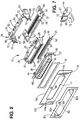
- FIGS. 1 and 2 a first embodiment of an electrical connector assembly, generally designated 10, is shown for mounting on a circuit board 12 (Fig. 2) and through an opening 14 in a panel 16.
- FIG. 2 also shows an electromagnetic gasket 18 which may be provided between the connector assembly and a rear or first side 16a of panel 16 when the connector is mounted through opening 14 in the panel.
- electrical connector assembly 10 includes an insulating or dielectric connector housing, generally designated 20; a metal shield, generally designated 22 which is positionable over the front of the housing; a terminal tail aligner, generally designated 24; and a multi-function mounting/latch component, generally designated 26, which facilitates both mounting the connector assembly to circuit board 12 as well as through opening 14 in panel 16 and can latchingly engage a mating connector.
- connector housing 20 of connector assembly 10 includes a main body portion 28 (Fig. 2) and a forwardly projecting mating portion 30.
- the housing mounts a plurality of rows of conductive terminals which include terminal contacts 32 projecting forwardly into mating portion 30 for engaging the contacts of an appropriate complementary mating connector.
- the housing 20 may be unitarily molded of plastic material or the like, and a pair of snap-latch bosses 34 are formed on both the top and bottom of the housing.
- a pair of mounting posts 36 project upwardly from body 28 of the housing.
- Shield 22 of connector assembly 10 may be deep drawn of sheet metal material.
- the shield includes a plate portion 38 for abutting against the front face of body 28 of housing 20, as well as a shroud portion 40 which surrounds mating portion 30 of the housing.
- the shield has a pair of snap-latches 44 projecting rearwardly from the top and bottom edges of plate portion 38 for engaging snap-latch bosses 34 of connector housing 20 to hold the shield in assembly on the housing as seen in FIG. 1.
- the shield has a pair of vertically elongated slots 46 formed in plate portion 38 at opposite ends of shroud portion 40, for purposes described hereinafter.
- Tail aligner 24 of connector assembly 10 may be molded of dielectric material such as plastic or the like and includes an elongated body portion 48.
- a plurality of passages 50 are formed through the body portion and through which tail portions of the terminals mounted within housing 20 extend for connection to circuit traces 52 (Fig. 2) on circuit board 12.
- a pair of mounting posts 54 project downwardly at opposite ends of the tail aligner for insertion into mounting hole 56 and elongated mounting hole 57 in the circuit board.
- Multi-function mounting/latch component 26 is a unique component in that it performs multiple functions and replaces multiple components of prior art connector assemblies.
- multi-function component 26 is a one-piece structure which may be fabricated of die-cast metal or the like.
- the multi-function component includes a transverse body 60 having a pair of mounting apertures 62 for receiving mounts posts 36 of connector body 20.
- a pair of generally cylindrical mounting bosses 64 project rearwardly at opposite ends of body 60.
- the mounting bosses are provided for receiving appropriate fasteners (not shown) which extend through the cylindrical bosses and into a pair of mounting holes 66 in circuit board 12.
- cylinder recesses 67 are provided for receiving second fasteners (not shown).
- the second fasteners extend through second mounting hole 58 in circuit board 12 and grip in the cylindrical recesses 67.
- a pair of latch arms 68 project forwardly at opposite ends of body 60 and have apertures 70 therethrough near forward distal ends of the latch arms.
- the upper and lower edges of latch arms 68 are provided with serrations 72 for purposes described hereinafter.
- an apertured locking boss 74 projects upwardly from body 60, generally at the center thereof, also for purposes to be described hereinafter.
- FIG. 1 shows connector housing 20, shield 22 and multi-function component 26 in assembled condition, in conjunction with electromagnetic gasket 18.
- the connector housing When so assembled, the connector housing is substantially surrounded by the metal shield and the die-cast metal multi-function component Therefore, the connector housing is hardly visible in FIG. 1.
- shield 22 When assembled as shown in FIG. 1, shield 22 is assembled over connector housing 20 with shroud portion 40 of the shield surrounding mating portion 30 of the housing. When fully assembled, snap latches 44 of the shield latchingly engage with snap-latch bosses 34 of the housing.
- Multi-function component 26 is assembled over body 28 of the connector housing in a forward linear direction by inserting latch arms 68 of the multi-component through slots 46 (Fig. 2) in plate portion 38 of the shield. During assembly, the multi-function component preferably is assembled to the housing first and then this subassembly is assembled to the shield.
- mounting posts 36 of the housing can be inserted into mounting apertures 62 of the multi-function component either by a press-fit or by swaging the posts once they are inserted through the apertures.
- Tail aligner 24 can be positioned over the terminal tails and the connector assembly can be mounted to circuit board 12 by appropriate fasteners extending through mounting bosses 64 of the multi-function component and into mounting holes 66 in the circuit board and through mounting hole 58 into cylindrical recess 67 in the mounting boss 64.
- the connector assembly 10 can be mounted through opening 14 in panel 16 before mounting the assembly to circuit board 12.
- FIGS. 3-5 show the connector assembly mounted through opening 14 (Fig. 2) in panel 16.
- mating portion 30 of connector housing 20 and surrounding shroud portion 40 of shield 22 extend through the opening in the panel.
- latch arms 68 which extend through slots 46 (Fig. 2) in the shield, extend through cutouts 14a (Fig. 2) at opposite ends of opening 14 in the panel. Therefore, as seen in FIGS.
- the majority of electrical connector assembly 10 is located on first side 16a of panel 16, while the mating portion of the connector housing surrounded by shroud portion 40 of the shield, along with latch arms 68 of multi-function component 26, project through the panel to a second or opposite side 16b thereof.
- a rigid latch in the form of a locking plate 80 (Figs. 2-5) made from thin metal is positioned over shroud portion 40 of shield 22 and latch arms 68 of multi-function component 26.
- FIG. 2 shows that locking plate 80 has an elongated opening 82 for surrounding these components.
- the elongated opening has top and bottom elongated edges 82a.
- the width of the elongated opening is such that top and bottom elongated edges 82a engage serrations 72 at the top and bottom of latch arms 68 of multi-component 26.
- the locking means can accommodate panels of varying thicknesses. If it is desired to solidly lock the entire assembly in position through panel 16, locking plate 80 has a hole 84 and panel 16 has a hole 86 through which a fastener, such as a bolt, can be inserted into apertured boss 74 of multi-component 26 to completely lock the connector assembly mounted to and through the panel.
- a fastener such as a bolt
- circuit board 12 can be mounted to multi-function component 26 either before or after the component mounts connector assembly 10 to and through panel 16.
- FIGS. 3-5 illustrate that the circuit board is to be mounted after the connector assembly is mounted to and through the panel.
- FIG. 3 shows tail portions 86 of the connector terminals in position for connection to circuit traces 52 of the circuit board.
- FIG. 6 shows an alternate embodiment of the invention wherein serrations 72 are formed on the outside surfaces of latch arms 68 of multi-function component 26, rather than on the top and bottom edges of the latch arms as in the first embodiment of FIGS. 1-5. These serrations engage opposite end edges 82b of opening 82 in locking plate 80. Otherwise, the connector assembly is substantially identical to that described above and, consequently, like reference numerals have been applied in FIG. 6 corresponding to like components described above in relation to the first embodiment of FIGS. 1-5.
- multi-function component 26 performs a plurality of functions.
- the component includes first means in the form of mounting bosses 64 and cylindrical recesses 67 for securing the connector assembly to circuit board 12.
- the component includes second means in the form of mounting apertures 62 cooperating with mounting posts 36 of the connector housing for mounting the housing at one side of panel 16 and through opening 14 in the panel.
- the component includes third means in the form of latch arms 68 which extend through the opening in the panel for engagement by locking means in the form of locking plate 80 to lock the entire connector assembly to and through the panel.
- multi-function component 26 includes fourth means in the form of apertures 70 in latch arms 68 for engaging appropriate latches on a complementary mating connector.
Landscapes
- Details Of Connecting Devices For Male And Female Coupling (AREA)
- Coupling Device And Connection With Printed Circuit (AREA)
- Connector Housings Or Holding Contact Members (AREA)
Description
- This invention generally relates to the art of electrical connectors and, particularly, to an electrical connector assembly for mounting to a panel through an opening in the panel where the other end of the connector is mountable on a printed circuit board.
- A typical electrical connector includes some form of insulating or dielectric housing mounting a plurality of terminals. The connector may be used in a wide range of electrical connection environments. For instance, the connector may be mounted on a printed circuit board for electrical connection to circuit traces on the board. The connector may be mounted to and through an opening in a panel from one side of the panel for mating with a complementary mating connector on an opposite side of the panel.
- Such connectors are disclosed in US-A-5 752 854, US-A-5 895 289, DE-A-36 12 318 or US-A-6 066 001.
- With such applications as described above, some form of mounting means typically must be provided for mounting the connector to the printed circuit board. Additional mounting means typically must be provided for mounting the connector through the opening in the panel. Still additional latching means must be provided on the connector for engagement by fasteners or other latches to hold the connector in the opening in the panel. Yet further latching means may be provided for latching the connector to the complementary mating connector. All of these functions and various mounting and/or latching means typically are separate components and unduly complicate the manufacturability and assembly of the connector. The present invention is directed to solving those problems by providing a unique multi-function mounting/latch component which performs a first function of mounting the connector to a printed circuit board, a second function of mounting the connector to the multi-function component, a third function of facilitating latching the connector in position in the panel and a fourth function of latching the connector to a mating connector.
- An object, therefore, of the invention is to provide a new and improved electrical connector assembly according to claim 1.
- According to one aspect of the invention, the first means is provided by at least one mounting boss on the multi-function component. The mounting boss receives an appropriate fastener for securing the multi-function component to the circuit board.
- According to another aspect of the invention, the second means includes at least one mounting post on one of the housing or the multi-function component insertable into a mounting aperture in the other of the housing or multi-function component. As disclosed herein, the second means includes a plurality of the mounting posts on the housing insertable into a corresponding plurality of mounting apertures in the multi-function component.
- According to a further aspect of the invention, the third means includes a latch arm projecting from the multi-function component through the panel. The locking means is engageable with the latch arm. As disclosed herein, the multi-function component is elongated and includes a pair of the latch arms at opposite ends thereof. The locking means is provided by a thin locking plate snappingly engageable with the serrations of the latch arms. The latch arms include the fourth means for latching to the mating connector.
- Other objects, features and advantages of the invention will be apparent from the following detailed description taken in connection with the accompanying drawings.
- The features of this invention which are believed to be novel are set forth with particularity in the appended claims. The invention, together with its objects and the advantages thereof, may be best understood by reference to the following description taken in conjunction with the accompanying drawings, in which like reference numerals identify like elements in the figures and in which:
- FIG. 1 is perspective view of an electrical connector assembly embodying the concepts of the invention;
- FIG. 2 is an exploded perspective view of the connector assembly in conjunction with a circuit board and a panel through which the assembly is mounted;
- FIG. 3 is a top plan view of the connector assembly mounted through the panel but without the circuit board;
- FIG. 4 is an end elevational view of the connector assembly mounted through the panel;
- FIG. 5 is an enlarged, fragmented plan view of one end of the connector assembly mounted through the panel; and
- FIG. 6 is an enlarged, fragmented perspective view of one end of an alternate embodiment of the invention, with the connector assembly mounted through a panel.
- FIG. 7 is an enlarged, fragmented perspective view of the bottom of one end of the multi-function mounting/latch component of the connector assembly.
- Referring to the drawings in greater detail, and first to FIGS. 1 and 2, a first embodiment of an electrical connector assembly, generally designated 10, is shown for mounting on a circuit board 12 (Fig. 2) and through an
opening 14 in apanel 16. FIG. 2 also shows anelectromagnetic gasket 18 which may be provided between the connector assembly and a rear orfirst side 16a ofpanel 16 when the connector is mounted through opening 14 in the panel. - Generally,
electrical connector assembly 10 includes an insulating or dielectric connector housing, generally designated 20; a metal shield, generally designated 22 which is positionable over the front of the housing; a terminal tail aligner, generally designated 24; and a multi-function mounting/latch component, generally designated 26, which facilitates both mounting the connector assembly tocircuit board 12 as well as through opening 14 inpanel 16 and can latchingly engage a mating connector. - More particularly,
connector housing 20 ofconnector assembly 10 includes a main body portion 28 (Fig. 2) and a forwardly projectingmating portion 30. The housing mounts a plurality of rows of conductive terminals which includeterminal contacts 32 projecting forwardly intomating portion 30 for engaging the contacts of an appropriate complementary mating connector. Thehousing 20 may be unitarily molded of plastic material or the like, and a pair of snap-latch bosses 34 are formed on both the top and bottom of the housing. In addition, a pair ofmounting posts 36 project upwardly frombody 28 of the housing. -
Shield 22 ofconnector assembly 10 may be deep drawn of sheet metal material. The shield includes aplate portion 38 for abutting against the front face ofbody 28 ofhousing 20, as well as ashroud portion 40 which surroundsmating portion 30 of the housing. The shield has a pair of snap-latches 44 projecting rearwardly from the top and bottom edges ofplate portion 38 for engaging snap-latch bosses 34 ofconnector housing 20 to hold the shield in assembly on the housing as seen in FIG. 1. Lastly, the shield has a pair of verticallyelongated slots 46 formed inplate portion 38 at opposite ends ofshroud portion 40, for purposes described hereinafter. - Tail aligner 24 of
connector assembly 10 may be molded of dielectric material such as plastic or the like and includes anelongated body portion 48. A plurality ofpassages 50 are formed through the body portion and through which tail portions of the terminals mounted withinhousing 20 extend for connection to circuit traces 52 (Fig. 2) oncircuit board 12. A pair ofmounting posts 54 project downwardly at opposite ends of the tail aligner for insertion intomounting hole 56 andelongated mounting hole 57 in the circuit board. - Multi-function mounting/
latch component 26 is a unique component in that it performs multiple functions and replaces multiple components of prior art connector assemblies. In particular,multi-function component 26 is a one-piece structure which may be fabricated of die-cast metal or the like. The multi-function component includes atransverse body 60 having a pair ofmounting apertures 62 for receivingmounts posts 36 ofconnector body 20. A pair of generallycylindrical mounting bosses 64 project rearwardly at opposite ends ofbody 60. The mounting bosses are provided for receiving appropriate fasteners (not shown) which extend through the cylindrical bosses and into a pair ofmounting holes 66 incircuit board 12. As shown in FIG. 7,cylinder recesses 67 are provided for receiving second fasteners (not shown). The second fasteners extend throughsecond mounting hole 58 incircuit board 12 and grip in thecylindrical recesses 67. A pair oflatch arms 68 project forwardly at opposite ends ofbody 60 and haveapertures 70 therethrough near forward distal ends of the latch arms. As best seen in FIG. 1, the upper and lower edges oflatch arms 68 are provided withserrations 72 for purposes described hereinafter. Lastly, an aperturedlocking boss 74 projects upwardly frombody 60, generally at the center thereof, also for purposes to be described hereinafter. - FIG. 1 shows
connector housing 20,shield 22 andmulti-function component 26 in assembled condition, in conjunction withelectromagnetic gasket 18. When so assembled, the connector housing is substantially surrounded by the metal shield and the die-cast metal multi-function component Therefore, the connector housing is hardly visible in FIG. 1. - When assembled as shown in FIG. 1,
shield 22 is assembled overconnector housing 20 withshroud portion 40 of the shield surroundingmating portion 30 of the housing. When fully assembled, snaplatches 44 of the shield latchingly engage with snap-latch bosses 34 of the housing.Multi-function component 26 is assembled overbody 28 of the connector housing in a forward linear direction by insertinglatch arms 68 of the multi-component through slots 46 (Fig. 2) inplate portion 38 of the shield. During assembly, the multi-function component preferably is assembled to the housing first and then this subassembly is assembled to the shield. In that way, mountingposts 36 of the housing can be inserted into mountingapertures 62 of the multi-function component either by a press-fit or by swaging the posts once they are inserted through the apertures.Tail aligner 24 can be positioned over the terminal tails and the connector assembly can be mounted tocircuit board 12 by appropriate fasteners extending through mountingbosses 64 of the multi-function component and into mountingholes 66 in the circuit board and through mountinghole 58 intocylindrical recess 67 in the mountingboss 64. - The
connector assembly 10 can be mounted throughopening 14 inpanel 16 before mounting the assembly tocircuit board 12. With this scenario, reference is made to FIGS. 3-5 which show the connector assembly mounted through opening 14 (Fig. 2) inpanel 16. In essence,mating portion 30 ofconnector housing 20 and surroundingshroud portion 40 ofshield 22 extend through the opening in the panel. In addition, latcharms 68 which extend through slots 46 (Fig. 2) in the shield, extend throughcutouts 14a (Fig. 2) at opposite ends of opening 14 in the panel. Therefore, as seen in FIGS. 3-5, the majority ofelectrical connector assembly 10 is located onfirst side 16a ofpanel 16, while the mating portion of the connector housing surrounded byshroud portion 40 of the shield, along withlatch arms 68 ofmulti-function component 26, project through the panel to a second oropposite side 16b thereof. - In order to lock the connector assembly in position mounted through
opening 14 inpanel 16, a rigid latch in the form of a locking plate 80 (Figs. 2-5) made from thin metal is positioned overshroud portion 40 ofshield 22 and latcharms 68 ofmulti-function component 26. FIG. 2 shows that lockingplate 80 has an elongatedopening 82 for surrounding these components. The elongated opening has top and bottomelongated edges 82a. According to the invention, the width of the elongated opening is such that top and bottomelongated edges 82a engageserrations 72 at the top and bottom oflatch arms 68 ofmulti-component 26. With the locking plate being fabricated of rigid material, the top and bottom edges snappingly engageserrations 72. By using serrations, the locking means can accommodate panels of varying thicknesses. If it is desired to solidly lock the entire assembly in position throughpanel 16, lockingplate 80 has ahole 84 andpanel 16 has ahole 86 through which a fastener, such as a bolt, can be inserted intoapertured boss 74 ofmulti-component 26 to completely lock the connector assembly mounted to and through the panel. - As stated above,
circuit board 12 can be mounted tomulti-function component 26 either before or after the component mountsconnector assembly 10 to and throughpanel 16. FIGS. 3-5 illustrate that the circuit board is to be mounted after the connector assembly is mounted to and through the panel. However, FIG. 3 showstail portions 86 of the connector terminals in position for connection to circuit traces 52 of the circuit board. - FIG. 6 shows an alternate embodiment of the invention wherein
serrations 72 are formed on the outside surfaces oflatch arms 68 ofmulti-function component 26, rather than on the top and bottom edges of the latch arms as in the first embodiment of FIGS. 1-5. These serrations engage opposite end edges 82b of opening 82 in lockingplate 80. Otherwise, the connector assembly is substantially identical to that described above and, consequently, like reference numerals have been applied in FIG. 6 corresponding to like components described above in relation to the first embodiment of FIGS. 1-5. - From the foregoing, it can be seen that
multi-function component 26 performs a plurality of functions. The component includes first means in the form of mountingbosses 64 andcylindrical recesses 67 for securing the connector assembly tocircuit board 12. The component includes second means in the form of mountingapertures 62 cooperating with mountingposts 36 of the connector housing for mounting the housing at one side ofpanel 16 and through opening 14 in the panel. The component includes third means in the form oflatch arms 68 which extend through the opening in the panel for engagement by locking means in the form of lockingplate 80 to lock the entire connector assembly to and through the panel. Finally,multi-function component 26 includes fourth means in the form ofapertures 70 inlatch arms 68 for engaging appropriate latches on a complementary mating connector. It will be understood that the invention may be embodied in other specific forms without departing from the claims. The present examples and embodiments, therefore, are to be considered in all respects as illustrative and not restrictive, and the invention is not to be limited to the details given herein.
Claims (9)
- An electrical connector assembly (10) for mounting to a first side (16a) of a panel (16) and through an opening (14) in the panel, comprising:a connector housing (20), a portion of which mounts through the opening in the panel, and carrying a plurality of terminals (32); anda multi-function mounting/latch component (26) having first means for mounting (64,67) the connector housing on a circuit board (12), second means (62) for mounting the connector housing (20) to said multi-function component at said first side (16a) of the panel;
wherein
said multi function mounting/latch component (26) further including third means (68) for mounting the connector assembly to the panel extending through the opening (14) to a second side (16b) of the panel comprising a latch arm (68) projecting from the multi-function component (26) through the opening and engageable with means for locking (80) at said second side of the panel to hold the connector assembly to the panel
characterised in that
said latch arm (68) further including latching serrations (72) engageable by said means for locking (80) to accommodate panels of varying thicknesses. - The electrical connector assembly of claim 1 wherein said first means for mounting comprise at least one mounting boss (64) for receiving an appropriate fastener for securing the connector assembly to the circuit board (12).
- The electrical connector assembly of claim 1 or 2 wherein said second means for mounting comprise a mounting aperture (62) in the multi-function component into which is inserted at least one mounting post (36) on the housing.
- The electrical connector assembly of claim 3 wherein said second means comprise a plurality of said mounting posts (36, 36) on the housing insertable into a corresponding plurality of mounting apertures (62, 62) in the multi-function component.
- The electrical connector assembly of one of claims 1 to 4 wherein said locking means include a thin locking plate (80) engageable with the latch arm (68).
- The electrical connector assembly of claim 5, wherein said latch arm (68) includes a plurality of latching serrations (72) engageable by edges (82a, 82b) of said locking plate (80).
- The electrical connector assembly of one of claims 1 to 6 wherein said multi-function component (26) is elongated and includes a pair of said latch arms (68) at opposite ends thereof.
- The electrical connector assembly of one of claims 1 to 7 wherein said third means for mounting include means for latching (70) the connector assembly to a complementary mating connector at said second side (16b) of the panel.
- The electrical connector assembly of claim 8 wherein said third means for mounting comprise a latch arm (68) projecting from the multi-function component (26) through the panel (16), said means for locking (80) being engageable with the latch arm (68), and said means for latching comprising a latching aperture (70) through the latch arm (68).
Applications Claiming Priority (3)
| Application Number | Priority Date | Filing Date | Title |
|---|---|---|---|
| US177511 | 1988-04-04 | ||
| US10/177,511 US6659796B1 (en) | 2002-06-21 | 2002-06-21 | Multi-function mounting/latch component for electrical connectors |
| PCT/US2003/018920 WO2004001914A1 (en) | 2002-06-21 | 2003-06-17 | Multi-function mounting/latch arrangement for electrical connectors |
Publications (2)
| Publication Number | Publication Date |
|---|---|
| EP1516399A1 EP1516399A1 (en) | 2005-03-23 |
| EP1516399B1 true EP1516399B1 (en) | 2006-01-11 |
Family
ID=29711296
Family Applications (1)
| Application Number | Title | Priority Date | Filing Date |
|---|---|---|---|
| EP03737114A Expired - Lifetime EP1516399B1 (en) | 2002-06-21 | 2003-06-17 | Multi-function mounting/latch arrangement for electrical connectors |
Country Status (8)
| Country | Link |
|---|---|
| US (1) | US6659796B1 (en) |
| EP (1) | EP1516399B1 (en) |
| JP (1) | JP4134032B2 (en) |
| CN (1) | CN100409502C (en) |
| AU (1) | AU2003238218A1 (en) |
| DE (1) | DE60303208T2 (en) |
| TW (1) | TWI228333B (en) |
| WO (1) | WO2004001914A1 (en) |
Families Citing this family (16)
| Publication number | Priority date | Publication date | Assignee | Title |
|---|---|---|---|---|
| JP4082694B2 (en) * | 2004-03-30 | 2008-04-30 | 日本航空電子工業株式会社 | EMI countermeasure connector |
| EP1655813A1 (en) * | 2004-11-09 | 2006-05-10 | Phoenix Contact GmbH & Co. KG | Attachment for electrical connector |
| CN2831226Y (en) * | 2005-06-28 | 2006-10-25 | 鸿富锦精密工业(深圳)有限公司 | Expansion card recess baffle |
| JP4939257B2 (en) * | 2007-02-28 | 2012-05-23 | 富士通コンポーネント株式会社 | connector |
| US7727001B2 (en) * | 2007-10-17 | 2010-06-01 | Tyco Electronics Corporation | Electrical connector assembly |
| CN201562815U (en) * | 2008-09-09 | 2010-08-25 | 莫列斯公司 | Connector assembly |
| CN102201621A (en) * | 2010-03-25 | 2011-09-28 | 深圳富泰宏精密工业有限公司 | Battery connector and electronic device applying same |
| US7918672B1 (en) * | 2010-07-16 | 2011-04-05 | Cheng Uei Precision Industry Co., Ltd. | Battery connector |
| JP5887150B2 (en) * | 2012-01-26 | 2016-03-16 | Kyb株式会社 | Bus bar |
| TWI555284B (en) * | 2013-01-16 | 2016-10-21 | Molex Inc | Connector |
| US10263349B2 (en) * | 2017-02-14 | 2019-04-16 | Te Connectivity Corporation | Connector with coupling device for stabilized latching |
| US10559917B2 (en) * | 2017-02-16 | 2020-02-11 | Foxconn Interconnect Technology Limited | Magnetic electrical connector assembly |
| CN108448301B (en) * | 2017-02-16 | 2021-04-20 | 富士康(昆山)电脑接插件有限公司 | Electrical connector |
| JP7432990B2 (en) * | 2018-11-13 | 2024-02-19 | タイコエレクトロニクスジャパン合同会社 | electrical equipment |
| US11682853B2 (en) * | 2021-05-05 | 2023-06-20 | Te Connectivity Solutions, Gmbh | Electrical connector assembly having a connector mounting bracket |
| US20250055237A1 (en) * | 2023-08-11 | 2025-02-13 | Whirlpool Corporation | Compact end of line bracket and cap |
Family Cites Families (21)
| Publication number | Priority date | Publication date | Assignee | Title |
|---|---|---|---|---|
| EP0223869B1 (en) | 1985-11-21 | 1990-01-17 | C.A. Weidmüller GmbH & Co. | Arrangement of feed-through terminals |
| DE3612318A1 (en) * | 1986-04-11 | 1987-10-15 | Siemens Ag | INSERTED WITHIN A TELEPHONE STATION, ACCESSIBLE FROM THE OUTSIDE |
| US4906208A (en) | 1987-05-15 | 1990-03-06 | Hirose Electric Co., Ltd. | Electrical connector |
| US4822303A (en) | 1987-05-18 | 1989-04-18 | Hirose Electric Co., Ltd. | Electrical connector |
| JPS6424373A (en) | 1987-07-13 | 1989-01-26 | Amp Inc | Shielded connector |
| US4808125A (en) | 1987-08-31 | 1989-02-28 | Amp Incorporated | Connector assembly with diecast housing and drawn shell |
| US4812133A (en) | 1988-06-30 | 1989-03-14 | Amp Incorporated | Floating mounting means for electrical connector assembly |
| US4911659A (en) * | 1989-04-21 | 1990-03-27 | Amp Incorporated | Electrical connector and a retention bracket therefor |
| US5037331A (en) | 1989-09-27 | 1991-08-06 | Itt Corporation | Shielded interface connector |
| US5044985A (en) * | 1990-01-24 | 1991-09-03 | Light Sheen | Type of fixed sleeve for a cigarette lighter seat |
| US5037325A (en) | 1990-10-05 | 1991-08-06 | Molex Incorporated | Panel mounted electrical connector |
| US5174789A (en) | 1992-01-21 | 1992-12-29 | Foxconn International, Inc. | Electrical connector with enhanced coupling |
| US5288244A (en) * | 1993-04-19 | 1994-02-22 | Maxconn Incorporated | Connector assembly having fixed unitary fasteners for mounting to a panel |
| US5527991A (en) | 1993-11-03 | 1996-06-18 | Carlingswitch, Inc. | Grounding strap for panel mounted electrical switch |
| US6017233A (en) | 1994-12-14 | 2000-01-25 | Molex Incorporated | Floating panel mount system for electrical connectors |
| EP0764788B1 (en) | 1995-09-19 | 2001-09-12 | Daiwa Kasei Kogyo Kabushiki Kaisha | Component retaining legs |
| US5752854A (en) | 1997-02-18 | 1998-05-19 | The Whitaker Corporation | Panel mount structure |
| US5895289A (en) * | 1997-08-27 | 1999-04-20 | The Whitaker Corporation | Retainer to mount a connector in a panel |
| JP3262758B2 (en) * | 1998-09-14 | 2002-03-04 | 日本圧着端子製造株式会社 | Flanged connector |
| US6066001A (en) * | 1998-11-30 | 2000-05-23 | 3Com Corporation | Coupler for minimizing EMI emissions |
| US6443768B1 (en) * | 2001-09-14 | 2002-09-03 | Molex Incorporated | Small form factor connector cage |
-
2002
- 2002-06-21 US US10/177,511 patent/US6659796B1/en not_active Expired - Fee Related
-
2003
- 2003-06-17 CN CNB038142759A patent/CN100409502C/en not_active Expired - Fee Related
- 2003-06-17 EP EP03737114A patent/EP1516399B1/en not_active Expired - Lifetime
- 2003-06-17 JP JP2004515814A patent/JP4134032B2/en not_active Expired - Fee Related
- 2003-06-17 AU AU2003238218A patent/AU2003238218A1/en not_active Abandoned
- 2003-06-17 WO PCT/US2003/018920 patent/WO2004001914A1/en not_active Ceased
- 2003-06-17 DE DE60303208T patent/DE60303208T2/en not_active Expired - Fee Related
- 2003-06-20 TW TW092116815A patent/TWI228333B/en active
Also Published As
| Publication number | Publication date |
|---|---|
| JP2006514772A (en) | 2006-05-11 |
| DE60303208T2 (en) | 2006-10-05 |
| CN1663084A (en) | 2005-08-31 |
| DE60303208D1 (en) | 2006-04-06 |
| EP1516399A1 (en) | 2005-03-23 |
| TW200401475A (en) | 2004-01-16 |
| JP4134032B2 (en) | 2008-08-13 |
| TWI228333B (en) | 2005-02-21 |
| WO2004001914A1 (en) | 2003-12-31 |
| US6659796B1 (en) | 2003-12-09 |
| AU2003238218A1 (en) | 2004-01-06 |
| CN100409502C (en) | 2008-08-06 |
Similar Documents
| Publication | Publication Date | Title |
|---|---|---|
| US6210219B1 (en) | Low profile electrical connector with improved board lock | |
| EP1026785B1 (en) | Adapter frame assembly for electrical connectors | |
| US6659796B1 (en) | Multi-function mounting/latch component for electrical connectors | |
| EP1026784B1 (en) | Shielded electrical connector | |
| US6086421A (en) | Electrical connector with one-piece shield | |
| US6206728B1 (en) | Shielded electrical connector system | |
| US6007382A (en) | Electrical connector | |
| US6270379B1 (en) | Connector with securely retained contacts | |
| US6227879B1 (en) | Electrical connector with grounding shroud having board-locks for grasping a circuit board | |
| US20040018766A1 (en) | Electrical connector having retention system for mounting onto a printed circuit board | |
| KR200146618Y1 (en) | Electrical connector | |
| EP0561497B1 (en) | Surface mount electrical connector and shield therefor | |
| US6537084B2 (en) | Electrical connector with electrical shield having latch and mounting arms | |
| US6210226B1 (en) | Electrical connector having enhanced sideward impact resisting structure | |
| US5820393A (en) | Board mounted electrical connector with multi-function board lock | |
| US7086889B2 (en) | Interlocking member for an electrical connector | |
| US5667411A (en) | Electrical connector having terminal alignment means | |
| US6267624B1 (en) | Electrical connector | |
| US6319063B1 (en) | Shielded electrical connector | |
| US20020081900A1 (en) | Compact electrical connector having boardlocks | |
| US6210225B1 (en) | Electrical connector with a pick-up cover | |
| US7044790B2 (en) | Electrical connector with electrically connecting inner and outer shells | |
| US6722920B2 (en) | Electrical connector assembly with securement device | |
| US7163408B1 (en) | Electrical connector | |
| US7059915B1 (en) | Panel mounted modular jack terminated to a circuit board |
Legal Events
| Date | Code | Title | Description |
|---|---|---|---|
| PUAI | Public reference made under article 153(3) epc to a published international application that has entered the european phase |
Free format text: ORIGINAL CODE: 0009012 |
|
| 17P | Request for examination filed |
Effective date: 20050108 |
|
| AK | Designated contracting states |
Kind code of ref document: A1 Designated state(s): AT BE BG CH CY CZ DE DK EE ES FI FR GB GR HU IE IT LI LU MC NL PT RO SE SI SK TR |
|
| AX | Request for extension of the european patent |
Extension state: AL LT LV MK |
|
| GRAP | Despatch of communication of intention to grant a patent |
Free format text: ORIGINAL CODE: EPIDOSNIGR1 |
|
| DAX | Request for extension of the european patent (deleted) | ||
| RBV | Designated contracting states (corrected) |
Designated state(s): DE FR GB SE |
|
| GRAS | Grant fee paid |
Free format text: ORIGINAL CODE: EPIDOSNIGR3 |
|
| GRAA | (expected) grant |
Free format text: ORIGINAL CODE: 0009210 |
|
| AK | Designated contracting states |
Kind code of ref document: B1 Designated state(s): DE FR GB SE |
|
| REG | Reference to a national code |
Ref country code: SE Ref legal event code: TRGR |
|
| REF | Corresponds to: |
Ref document number: 60303208 Country of ref document: DE Date of ref document: 20060406 Kind code of ref document: P |
|
| ET | Fr: translation filed | ||
| PLBE | No opposition filed within time limit |
Free format text: ORIGINAL CODE: 0009261 |
|
| STAA | Information on the status of an ep patent application or granted ep patent |
Free format text: STATUS: NO OPPOSITION FILED WITHIN TIME LIMIT |
|
| 26N | No opposition filed |
Effective date: 20061012 |
|
| PGFP | Annual fee paid to national office [announced via postgrant information from national office to epo] |
Ref country code: DE Payment date: 20080731 Year of fee payment: 6 |
|
| PGFP | Annual fee paid to national office [announced via postgrant information from national office to epo] |
Ref country code: FR Payment date: 20080617 Year of fee payment: 6 |
|
| PGFP | Annual fee paid to national office [announced via postgrant information from national office to epo] |
Ref country code: GB Payment date: 20080627 Year of fee payment: 6 |
|
| PGFP | Annual fee paid to national office [announced via postgrant information from national office to epo] |
Ref country code: SE Payment date: 20080627 Year of fee payment: 6 |
|
| GBPC | Gb: european patent ceased through non-payment of renewal fee |
Effective date: 20090617 |
|
| REG | Reference to a national code |
Ref country code: FR Ref legal event code: ST Effective date: 20100226 |
|
| PG25 | Lapsed in a contracting state [announced via postgrant information from national office to epo] |
Ref country code: FR Free format text: LAPSE BECAUSE OF NON-PAYMENT OF DUE FEES Effective date: 20090630 |
|
| PG25 | Lapsed in a contracting state [announced via postgrant information from national office to epo] |
Ref country code: GB Free format text: LAPSE BECAUSE OF NON-PAYMENT OF DUE FEES Effective date: 20090617 |
|
| PG25 | Lapsed in a contracting state [announced via postgrant information from national office to epo] |
Ref country code: DE Free format text: LAPSE BECAUSE OF NON-PAYMENT OF DUE FEES Effective date: 20100101 |
|
| PG25 | Lapsed in a contracting state [announced via postgrant information from national office to epo] |
Ref country code: SE Free format text: LAPSE BECAUSE OF NON-PAYMENT OF DUE FEES Effective date: 20090618 |