EP1515594A2 - Arrangement for plasma generation - Google Patents
Arrangement for plasma generation Download PDFInfo
- Publication number
- EP1515594A2 EP1515594A2 EP04292189A EP04292189A EP1515594A2 EP 1515594 A2 EP1515594 A2 EP 1515594A2 EP 04292189 A EP04292189 A EP 04292189A EP 04292189 A EP04292189 A EP 04292189A EP 1515594 A2 EP1515594 A2 EP 1515594A2
- Authority
- EP
- European Patent Office
- Prior art keywords
- electrodes
- candle
- spark plug
- voltage
- winding
- Prior art date
- Legal status (The legal status is an assumption and is not a legal conclusion. Google has not performed a legal analysis and makes no representation as to the accuracy of the status listed.)
- Granted
Links
Images


Classifications
-
- H—ELECTRICITY
- H01—ELECTRIC ELEMENTS
- H01T—SPARK GAPS; OVERVOLTAGE ARRESTERS USING SPARK GAPS; SPARKING PLUGS; CORONA DEVICES; GENERATING IONS TO BE INTRODUCED INTO NON-ENCLOSED GASES
- H01T13/00—Sparking plugs
- H01T13/50—Sparking plugs having means for ionisation of gap
-
- H—ELECTRICITY
- H05—ELECTRIC TECHNIQUES NOT OTHERWISE PROVIDED FOR
- H05H—PLASMA TECHNIQUE; PRODUCTION OF ACCELERATED ELECTRICALLY-CHARGED PARTICLES OR OF NEUTRONS; PRODUCTION OR ACCELERATION OF NEUTRAL MOLECULAR OR ATOMIC BEAMS
- H05H1/00—Generating plasma; Handling plasma
- H05H1/24—Generating plasma
- H05H1/2406—Generating plasma using dielectric barrier discharges, i.e. with a dielectric interposed between the electrodes
-
- H—ELECTRICITY
- H01—ELECTRIC ELEMENTS
- H01T—SPARK GAPS; OVERVOLTAGE ARRESTERS USING SPARK GAPS; SPARKING PLUGS; CORONA DEVICES; GENERATING IONS TO BE INTRODUCED INTO NON-ENCLOSED GASES
- H01T13/00—Sparking plugs
- H01T13/52—Sparking plugs characterised by a discharge along a surface
-
- H—ELECTRICITY
- H05—ELECTRIC TECHNIQUES NOT OTHERWISE PROVIDED FOR
- H05H—PLASMA TECHNIQUE; PRODUCTION OF ACCELERATED ELECTRICALLY-CHARGED PARTICLES OR OF NEUTRONS; PRODUCTION OR ACCELERATION OF NEUTRAL MOLECULAR OR ATOMIC BEAMS
- H05H1/00—Generating plasma; Handling plasma
- H05H1/24—Generating plasma
- H05H1/52—Generating plasma using exploding wires or spark gaps
Definitions
- the present invention relates generally to the plasma generation in a gas, and more particularly plasma generating systems between two electrodes.
- Plasma generation is especially used for the controlled ignition of engines internal combustion by the electrodes of a candle.
- Ignition of internal combustion engines essence, consisting in initiating the combustion of a air-fuel mixture in a combustion chamber said engine, is relatively well controlled in the current engines.
- spark-ignition engines with indirect injection conventionally, a candle and a upstream electronic device can generate a spark capable of transmitting to the mixture a sufficient energy for its combustion.
- the formation of this discharge requires breakdown voltages high (of the order of 30 kV per mm), so that one limits the inter-electrode space of the candles to approximately 1 mm, relatively unfavorable distance to the initiation of combustion.
- stratified mixtures have therefore been developed.
- a stratified blend presents a wealth that decreases at as you move away from the candle.
- the stratification of the mixture in the combustion chamber is for example obtained by guiding the fuel jet so that the jet meets the candle at the moment of the production of the spark.
- the guidance of the jet is especially obtained by aerodynamic phenomena, generated for example by a suitable form of the piston.
- New spark plugs on the surface produce larger sparks to treat the problem of the space-time appointment. We turn on thus a higher mixing volume. The probability initiation of combustion is then very widely increased in an ignition direct injection engine ordered and laminated mix.
- Such candles are especially described in patent applications FR97-14799, FR99-09473 and FROO-13821. Such candles generate significant sparks from reduced potential differences.
- the candles to surface sparks exhibit a dielectric separating the electrodes in the area where the distance the separating is the weakest; we guide sparks formed between the electrodes on the surface dielectric. These candles amplify the inter-electrode field on the surface of the dielectric. We charge for this gradually the basic abilities formed by the dielectric and an underlying electrode.
- the candles generate a spark propagating along the surface of the insulation in areas where the field electric in the air is the strongest.
- a device conventional engine ignition coupled with such candles typically generates sparks presenting a length of 4 mm with breakdown voltages between 5 and 25 kV.
- the discharge has a probability of substantially identical appearance anywhere around insulation.
- classical candles generate an electric arc occurring systematically in the same volume extremely reduced.
- This ignition method by plasma generation still has disadvantages. It happens in particular a passage to the arc following a single line. The initiation of combustion is not optimal.
- the invention also relates to a method of plasma generation between two electrodes separated by a dielectric material, the method comprising a step of applying an alternating voltage with a frequency greater than 1 MHz and a amplitude between peaks greater than 5 KV between electrodes.
- branched plasma used later refers to the simultaneous generation of at least several lines or ionization paths in a given volume, their branches are also omnidirectional.
- a plasma of volume implies the warming of the whole volume in which he has to generated, the branched plasma only requires the heating in the path of formed sparks. So, for a given volume, the energy required for a plasma branched is significantly lower than that required by a volume plasma.
- the invention makes it possible to easily generate a plasma of volume or a branched plasma.
- plasmas can especially be used to initiate a combustion of fuel in a combustion engine.
- the plasma as well generated can also be used in other applications, such as gas depollution exhausts, the disinfection of air conditioning, air filter cleaning or surface treatment.
- Combustion density will be called any molar density of gas greater than 5 * 10 -2 mol / L.
- a stream of positive ionization propagating from the anode will be referred to as a streamer.
- the invention proposes to apply a voltage alternative of frequency higher than 1MHz and amplitude between peaks greater than 5 kV between two plasma generation electrodes, separated by a element made of dielectric material. This excitement will be referred to as the radiofrequency excitation suite. This generates a plasma of volume or a plasma branched.
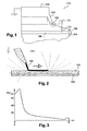
- Figure 1 illustrates details of the structure of a surface spark spark plug for which the application of a radiofrequency excitation is particularly advantageous. We go previously describe the operation of such candle.
- the surface effect candle 110 includes a head of candle destined to debouch in the room of combustion in the lower wall of the cylinder head of an engine.
- the candle comprises an electrode cylindrical low voltage that serves as a metal base 103 for screwing into a recess made in the engine cylinder head and opening inside the combustion chamber.
- the pellet 103 is intended to be electrically connected to the ground.
- the cap 103 surrounds a high voltage electrode cylindrical 106 disposed in a central position.
- the electrode 106 is intended to be connected to a generator of a high ignition voltage.
- the electrode 106 is isolated from the cap 103 via a insulating sleeve 100.
- the insulating sleeve is constituted of a material whose relative permittivity is greater than 3, for example a ceramic.
- the candle has a space 105 separating the dielectric 100 and one end of the electrode 103.
- the electrode 106 and the insulating sleeve 100 protrude by a length 1 outside the base 103.
- This length 1 corresponds substantially to the length of the spark generated when a high voltage is applied between the electrodes 106 and 103.
- the base or low voltage electrode 103 includes monobloc a body and a connecting piece supporting a collapsed flange 101.
- the flange 101 has a beveled edge extending nearby immediate of the surface of the insulation 100.
- the dielectric 100 creates a field amplification electrostatic in the air in its vicinity.
- the spark generated between the beveled edge of the flange 101 of the base 103 and a free end 104 of the electrode 106 is propagated on the surface of the insulation 100, where the electric field in the air is the strongest.
- the formation of a spark is initiated by tearing in the middle of a few electrons subject to an important electric field.
- electrons of the collar are accelerated by the electrostatic forces generated and strike molecules of the air.
- the end of the collar is the area that undergoes the most electrostatic field important, and thus constitutes the starting point of the first avalanche.
- the molecules of the air release a electron and an ionizing photon in turn other molecules of air.
- a chain reaction ionizes the air in the space 105 between the electrode 103 and the dielectric 100.
- the gas space 105 makes it possible to perform a prior ionization with a difference potential between the electrodes 103 and 106 relatively limited.
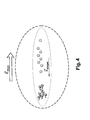
- a conductive channel is thus created, as illustrated in Figure 2.
- the broken lines represent equipotentials of the electrostatic field when a high voltage is applied between the electrodes 103 and 106.
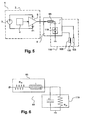
- FIG. 3 represents an example of amplitude of electrostatic field between the end of the flange 101 and the end of the electrode 106, A designating the end of the flange, B designating the end 104 of the electrode 106.
- the insulation is separated of the electrode 103 by an air space.
- This space is not essential for the operation of the candle but facilitates the making of the candle with a collar with a very sharp angle near the surface of the insulation. It also reduces the influence of fouling phenomena.
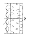
- FIG. 4 schematically represents the electrostatic field when leaving an avalanche.
- the present invention proposes, other, an electrical excitation capable of reversing the polarity of the global field imposed before the electrons could not recombine with the atoms present in the middle.
- a polarization wave propagates thus oscillatory way at the frequency of the excitation, recovering at each period the charges deposited at the previous period.
- Each alternation then produces a wave propagation larger than the previous; it is thus possible to obtain sparks of very long lengths with voltage amplitudes between the electrodes relatively limited.
- Radio frequency excitation also removes voltage variations from breakdown between successive cycles.
- electrodes and a insulation showing materials and geometry suitable for initiating combustion in a mixture with a density of combustion and to resist the plasma thus formed For an application to automotive ignition, the skilled person will use electrodes and a insulation showing materials and geometry suitable for initiating combustion in a mixture with a density of combustion and to resist the plasma thus formed.
- Plasma thus formed has many advantages in the context of automotive ignition: significant reduction in the rate of misfires in a stratified lean mixture system, reduction of wear of the electrodes and adaptation of the ignition initiation volume to density function. It is found that the excitation described is adapted to achieve ignition of a mixture having a density greater than 5 * 10 -2 mol / L. For this ignition application, the generator applies the excitation between 1.5 and 200 times per second, with an application duty ratio of between 10 and 1000, and preferably between 72 and 720.
- the radiofrequency excitation described is also adapted to a plasma deposition application in a gas having a density of between 10 -2 mol / L and 5 * 10 -2 mol / L.
- the gas used in this application may typically be nitrogen.
- the radiofrequency excitation is further adapted to an application for the depollution of a gas having a density of between 10 -2 mol / L and 5 * 10 -2 mol / L.
- the radiofrequency excitation is further adapted to a lighting application using a gas having a molar density of between 0.2 mol / L and 1 mol / L.
- the AC voltage of the amplifier 5 is applied on the resonator LC 6.
- the resonator LC 6 applies the alternating voltage according to the invention between the electrodes 103 and 106 of the candle head.
- the voltage supplied by the power supply 3 is less than 1000V and the power supply presents preferably a limited power. We can thus foresee that the energy applied between the electrodes is limited to 300mJ per ignition, for reasons of security. We also restrict the intensity in the voltage generator 2 and its power consumption.
- the power supply 3 can include a 12 Volt to Y Volt converter, Y being the voltage supplied by the power supply to the amplifier. We can thus generate the level of desired DC voltage from a voltage of drums.
- the stability of the DC voltage generated being a priori not a decisive criterion, we can plan to use a switching power supply for power the amplifier, for its qualities of robustness and simplicity.
- This voltage generator helps to focus the highest voltages on the resonator 6.
- the amplifier 5 thus deals with the tensions a lot smaller than the tensions applied between electrodes: we can therefore use an amplifier 5 reasonable cost and with characteristics of common components for the mass automobile production, whose reliability is furthermore proven.
- such a generator of voltage has a relatively large number of components reduced. There is thus a system for generating voltage with reliability, volume, weight and an attractive production facility, in especially for large series in one application automobile.
- the amplifier 5 can accumulate energy in the resonator 6 at each alternation of its voltage.
- a class 5 amplifier will preferably be used E, as detailed in US Pat. No. 5,187,580.
- amplifier can maximize the factor of surge.
- Such an amplifier achieves switching out of phase with the amplifier described in US Pat. No. 3,919,656 which aims to achieve switching at zero voltage and / or intensity and does not optimize the surge factor of the amplifier.
- the skilled person will associate well heard a switching device adapted to the chosen amplifier, to support the requirements of mounted in tension and have a speed of adequate switching.
- the preferred class E amplifier features a parallel resonator 62.
- This parallel resonator 62 is preferably made on the same map as the amplifier 5 and its switching control 4.
- the parallel resonator 62 temporarily stores the energy provided by the amplifier 5, and provides periodically this energy to the series 61 resonator.
- an amplifier 5 With specified supply voltage values in addition, an amplifier 5 will be used having an overvoltage coefficient of the order of 3. This overvoltage coefficient corresponds to the ratio between the voltage supplied by the low power supply voltage 3 and amplitude between peaks of voltage applied on the series resonator.
- the coefficient of overvoltage of the resonator series 61 associated is then of preferably between 40 and 200.
- the coefficient of overvoltage of the series resonator is notably limited by its angle of loss.
- FIG. 6 illustrates an electric model of this resonator.
- the inductance series 65 has in series an inductance L and a resistor Rs taking into account the skin effect in the radiofrequency domain.
- the capacitor 119 has in parallel a capacitance C and a resistor Rp.
- the resistor Rp corresponds, if appropriate, to the dissipation in the ceramic of the spark plug.
- the overvoltage coefficient is then defined as follows:
- the maximization of the overvoltage coefficient Q is then equivalent to the minimization of The VS .
- a high capacitance C and a reduced inductance L are then preferably selected.
- amplifiers 5 In general, we will use preferably an amplifier having a transistor MOSFET power as 51 commander switch the commutations at the terminals of the resonator 6.
- the Figures 7 and 8 illustrate two embodiments amplifiers 5 including M4 MOSFETs, such as Switches 51. Amplitude and frequency concerning the voltage to be generated between electrodes can be solved with a transistor Power MOSFET with characteristics following: insulation greater than 500 V, one drain current capacity greater than 30 A, a switching time less than 20 ns (and preferably of the order of 10ns in case of use of a servo loop) and a capacity in grid current up to 10A.
- This MOSFET transistor will also present preferably an inductance of less than 7 nH on its connections between its active silicon surface and the circuit board on which it is implanted. We avoid thus transients during high voltage peaks which would be detrimental to the rapid switching of the transistor.
- Figure 7 shows a first mode of realization of an amplifier 5 having such a switching control transistor M4.
- a midpoint transformer 56 is interposed between the command 4 and the M4 power MOSFET.
- the MOSFET M4 power can be controlled very quickly with a symmetrical voltage able to block it effectively. Indeed, the application of a tension negative on the gate of the MOSFET M4 allows to compensate for overvoltages caused by inductance M4 link with the rest of the circuit. The blocking of the transistor is thus facilitated, especially since negative voltage can discharge the capacity grid-drain particularly quickly.
- the amplifier 5 shown comprises two intermediate transistors M1 and M2 arranged for alternately feed the coils L1 and L2 of the primary of the midpoint transformer.
- a circuit 57 applies control signals respective on transistors M1 and M2.
- the signals of order do not overlap temporally for avoid a short circuit in the primary. Signals order also advantageously have substantially equal activation times to limit the magnetizing current in the transformer 56. It can be also compensate for unequal times activation by a high value of the inductor magnetising transformer 56.
- the timing diagram in Figure 9 illustrates different signals during the excitation of the series 61 resonator.
- curve 91 represents the current flowing through the resonator series 61.
- Curve 92 illustrates the voltage of the MOSFET M4 grid.
- Curve 93 illustrates the voltage at the input of the series 61 resonator.
- the amplifier 5 is advantageously integrated on a same circuit board 8. It is thus possible to integrate the transformer 56, the transistors M1 to M4 and the control circuit 57 on the same printed circuit, according to the diagram shown in Figure 10. We get so for a reduced cost an amplifier 5 very compact. The leakage inductance of the transformer and surges at the terminals of intermediate transistors M1 and M2.
- the left part of Figure 10 represents several elements of the amplifier 5 and their connections.
- the central part of Figure 10 represents the transistors M1 and M2 and their winding respective L11 and L12.
- the right part of Figure 10 schematically represents the different elements integrated on the printed circuit board 8.
- the assembly formed by transistors M1 to M4, coils L11, L12 and L2, is preferably disposed on an edge of the circuit 8.
- the windings can thus be arranged in the air gap of a split torus 81.
- FIG. 8 represents a second embodiment of an amplifier 5 having a MOSFET switching control transistor M4.
- the gates of the transistors M1 and M2 are linked. Transistors M1 and M2 thus switch simultaneously.
- the bipolar transistor M3 is therefore mounted as a follower. When M1 and M2 conduct, the bipolar transistor M3 is off, and therefore the MOSFET transistor M4 is also blocked.
- Intermediate transistors M1 and M2 having the following characteristics are preferably used: a control voltage of 5V, a nominal intensity of 8A at this voltage, a resistance R on less than 150 milliOhm and a response time of less than 20ns.
- a servo amplifier 5 the charge current applied to the resonator.
- the amplifier 5 thus has a device for measure 54 of the current applied to the input of the resonator 6.
- the instruction is applied to an input 58 of a comparator.
- the output signal of the comparator is applied on an amplification device 53 schematically represented.
- the enslavement is for example achieved by reinjecting in the amplifier 5 a voltage proportional to the current flowing in the load.
- the parallel resistance R2 of the transformer secondary fills preferentially two functions of servitude: the feedback of a signal proportional to the current in the load, and the phase shift of the intensity crossing the load in depending on its resistance value.
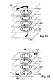
- FIG. 14 thus presents an example of transformer made on a printed circuit, facilitating the obtaining of such characteristics.
- the left part of Figure 14 represents independently the useful layers of the printed circuit.
- the right part of the figure represents these superimposed layers and assemblies.
- the conductive element 151 forms the primary of a transformer, and is arranged on a first face of the substrate 152. This conductive element 151 is in the example realized in substantially wire form.
- the conductive elements 153 and 154 form the secondary of the transformer. These conductive elements 153 and 154 are arranged on a second face of substrate 152, opposite the conductive element 152.
- the elements 153 and 154 are electrically connected on the one hand following the dotted line, and on the other hand by resistance 155. Resistance 155 can be used to measure the through current the conductive element 151 and to form the module of phase shift 55 described above.
- the LC 6 resonator includes a series 61 resonator and a parallel resonator 62.
- the series 61 resonator has a 119 series capacitance and a series inductor 65.
- the structure servo control includes an astable oscillator 52 (eg a slot generator) to generate the first alternations in the 119 series capacity and stabilize the oscillations in steady state.
- the servo structure adds the current measurement signal and the signal of the astable oscillator 52 and thus allows the amplifier in class E to achieve the commutations at the most favorable moments.
- the first niche generated by the oscillator 52 is approximately twice as much shorter than the following: thus, we can initialize the current in the series 65 inductance to the value of this current in steady state.
- the parallel resonator 62 includes an inductor 621 and a capacitor 622 arranged in parallel. All impulses to inductance 621 and capacitance 622 terminals are then equal. We can avoid over-dimensioning the switch 51 and exploit it optimally.
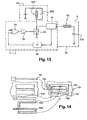
- Figure 12 shows a second variant.
- the control signal applied to the switch 51 generates a low voltage time slot, that is to say of the order of 5 ⁇ s, initiating the first alternation in the resonator 6.
- the servo signal then controls the switch 51.
- the loop of feedback of the present servo structure a high gain.
- the initial impulse operational servoing is sufficiently short, and the current flowing through the switch 51 remains reasonable. It is not necessary to oversize the switch 51 to perform the starting the servo, especially when the switch is formed of a MOSFET transistor of power.
- An advantageous combination of the parallel resonator 62 and Series 61 resonator optimizes operation of the system when the natural frequency of the resonator parallel 62 is slightly greater than that of resonator series 61.
- the voltage pulse generated by closing the switch transistor M4 has a duration less than the half-period of the resonator series 61.
- the impulse when closing the transistor switch M4 is anticipated by the diode internal inverse of the M4 transistor when the voltage of its drain passes by a null value.
- the upper limit value the currents in the transistor M4.
- the impedance characteristic of the parallel resonator 62 then approximately 32 ohms.
- the parallel resonator 62 can consider that the abilities between the turns of inductance 621 will be negligible compared to the capacity of the capacitor 622. It can therefore be realized the inductor 621 in the form of a superposition of substantially circular conductive tracks 623, carried out on the superimposed layers of a circuit printed. Examples of inductance structures 621 printed circuit boards are shown in FIGS. 16. The embodiments of these figures allow thus to realize a 621 inductor without core of ferrite. This reduces the cost and improves the performance of the inductor 621.
- each track 623 is surrounded of a closed loop 625, in order to reduce the radiation inductance 621 formed by the tracks.
- FIG. 15 represents a variant having a top layer and a layer lower that does not have a coil track.
- the upper layer and the lower layer present each a connection terminal 624 of the inductor 621.
- FIG. 16 represents a variant, in which the lower layer and the layer each have a coil track and a connection terminal. Curved lines 626 joining a connection pad at a connection terminal 624 represent an electrical connection reported on these printed circuit layers.
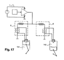
- each resonator 6 corresponds to a respective combustion chamber 141 and 142, both combustion chambers being in phase opposition.
- the amplifier 5 is controlled so that the voltage ignition is generated at a time during the compression and during relaxation for each room of combustion. Indeed, compression in a room 141 is synchronized with the trigger 142 in the other. When generating the voltage, the snapping in the relaxation room 142 is a lot faster than in the compression chamber 141. In indeed, the gas density in the relaxation chamber is much lower than the density in the chamber in compression.
- the equivalent discharge resistance of the relaxation chamber 142 is thus much more higher than that of the chamber in compression.
- the candle present in the chamber in compression continues then its rise in tension until breakdown.
- the gas density in the room in relaxation is weak enough not to change so annoying the overvoltage coefficient in the chamber in compression; the spark generation in the chamber in compression is thus undisturbed by the generating the voltage in the other chamber.
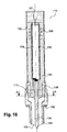
- FIG 18 shows a sectional view of a candle advantageously integrating a series resonator 61.
- the spark plug 110 has a connection terminal 131, connected to a first end of a winding inductive 112.
- the second end of winding inductive 112 is connected to an inner end of the high voltage electrode 106. This end is also in contact with an insulating element 111 forming the capacitor.
- the electrodes 103 and 106 are in this example separated by the dielectric material 100 for guiding the sparks between these electrodes.
- the 61 series resonator built into the 110 candle includes the inductive winding 112 and the insulating element 100 also forming the capacitor between the electrodes 103 and 106.
- the capacitor and the inductive winding 112 are arranged in series.
- the resonator series capacitance series 61 is formed of capacitor and capacitors internal parasites of the candle.
- This capacity 119 is arranged in series with an inductor 65 to form the 61 series resonator.
- the length of the connection between the inductance and the capacitor being thus reduced, reduces parasitic capacitances in the candle. It is thus easy to obtain a coefficient of overvoltage of the series resonator within the preferred range from 40 to 200 described above.
- the candle 110 is thus used to maintain the AC voltage between the electrodes 103 and 106, in the field of desired frequency.
- the series resonator built into the present candle preferably a single winding 112, facilitating the making such a candle.
- the only inductive coil 112 preferably has an axis (identified by the line dotted line) and consists of a plurality of superimposed turns along its axis. We thus hear that the projection of a turn is identical to the projection of all the turns along this axis. We then limit parasitic capacitances by not superimposing turns radially.
- the candle furthermore advantageously comprises a shielding 132 connected to a mass and surrounding the inductive winding 112.
- the field lines are thus closed within shielding 132.
- Shielding 132 thus reduces electromagnetic emissions parasite of the candle 110.
- the winding 112 can in effect generate intense electromagnetic fields with the radiofrequency excitation that is envisaged to apply between the electrodes. These fields can notably disrupt embedded systems of a vehicle or exceed thresholds defined in standards resignation.
- the shield 132 is preferably constituted a non-ferrous material with high conductivity, such than copper. One can use a loop conductor as shielding 132.
- the optimal ratio between their diameter is worth the number from Euler, approximately 2.72, if you want minimize the maximum electric field generated at the surface of the turns. This avoids phenomena of breakdown causing energy dissipation in the candle. We will then preferably choose a report between their diameter between 2.45 and 3.
- the use of two coils 112 wound on one another and connected in parallel makes it possible to reduce the resistance of the winding formed.
- the skin effect significantly increasing the resistance of the winding in the radio frequency range, is minimized by the winding one over the other of these two windings.
- the optimum ratio between the diameter of the shield 132 and the coil 112 is 2 by winding on one another two windings 112 connected in parallel by their ends.
- the two coils wound on one another have slightly different winding diameters and therefore slightly different inductances, which can disturb the operation of the candle in the radio frequency range. It has been determined that for the value 2 mentioned above, the difference of the inductances did not disturb the operation of the candle in the radiofrequency domain. In this case, a ratio of diameters between 1.35 and 1.5 will preferably be chosen.
- the coil 112 and the shield 132 are of preferably separated by an insulating sleeve 133 into one suitable dielectric material, in order to further reduce the risk of breakdown or effluvia, the cause of energy dissipation.
- the dielectric material may for example be one of the silicone resins marketed under the references Elastosil M4601, Elastosil RTV-2 or Elastosil RT622 (the latter having a breakdown voltage of 25 kV / mm and a dielectric constant of 2.8).
- All materials dielectric of the candle preferably has melting temperatures above 150 ° C.
- the coil-candle when the coil-candle includes several insulating elements contiguous, it exists a significant risk of creating air inclusions at the interface between these elements, especially are made of ceramic. However, for reasons constructive, it is envisaged that the coil-candle in most cases understands several elements contiguous insulators. In particular, the link between the insulation 134 of the coil and the insulator 111 of the head candle is also for the same reasons corona, a very important source of dissipation.
- the technique mentioned above can, according to a new embodiment, be put to use at the level of the ceramic to create equipotentials preventing the formation of electric discharges.
- Figure 19 shows a section of an element insulator 111 of candle head, also solving this problem.
- This insulating element 111 is intended to be associated with an insulating element 133 in the form of resin of silicone.
- This insulating element 111 has a non-circular section and is included in a room circular 136 belonging to the cathode 103. Thus, this element forms passages intended to let the silicone resin during its injection. Resin silicone can thus eliminate most of the air inclusions of the surface of the insulating elements.
- the dielectric material used for the insulation 100 can for example be a ceramic based on alumina, of aluminum nitride, aluminum oxide or silicon carbide.
- the candle 110 presents in in addition to a current measuring winding 139 fulfilling the function of module 54.
- This winding 139 includes several turns surrounding the winding 112.
- the winding 139 is preferably arranged to proximity of the connector 131 and at a distance from the head of candle, in an area where the voltages are relatively bass.
- the candle of the invention can integrate a certain number of other features, such as the seal of seat 130 of Figure 18 disposed against a shoulder of the cathode 103, and intended to ensure the sealing of the breech at the level of the candle light.
- the candle head is the part of the candle that is placed in the gas in which the plasma has to be form.
- This candle head preferably comprises three elements: a central electrode 106, a ground electrode 103 and an insulator 100. Geometry of these elements is decisive for ensuring formation of plasma volume or plasma branched to the desired location of the room, with the optimum properties, especially for ignition (volume important, optimal energy transfer to the gas, etc ).
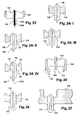
- Figures 20 to 27 illustrate different configurations of candle heads, advantageously included in candles adapted to generate a plasma between their electrodes and adapted to be powered by radiofrequency excitation.
- Figure 20 shows a first group of variants of candle heads, which we will call candles with capacitive propagation. These geometries of candle have a cathode 103 partially covered by the insulation 100 in the axis of the candle. This geometry generates a capacitive propagation of the spark on the surface of the insulation 100.
- Figure 20.I shows a head geometry of candle known in itself.
- the cathode 103 protrudes axially beyond insulation 100.
- An electric arc can be formed according to this direct route.
- the cathode 103 no longer projecting axially with respect to the insulation 100.
- Insulator 100, cathode 103 and anode 106 substantially form a flat surface, avoiding the forming an electric arc between the anode 106 and the cathode 103.
- the insulation 100 is protruding axially from the ends of the electrodes 103 and 106. This still allows extend the air path between the electrodes 103 and 106.
- the protrusion of the insulator 100 forms a boss round.
- the cathode 103 of this variant is arranged axially recessed with respect to the insulation.
- the central electrode or anode 106 is arranged flush with the insulation.
- Figure 22 proposes to make a cavity or a recess 120 in the insulator in order to amplify the depolarization phenomenon.
- the anode 106 presents also a growing section at its end, at 120.
- the final section of the anode 106 is greater than its intermediate section. This creates axially a vacuum 121 between the end of the anode and the insulator 100, which locally amplifies the electric field.
- the variants intended to avoid the formation of a direct arc between the electrodes function optimally in combination with radiofrequency excitation.
- excitation radiofrequency makes it possible to lengthen and bend the trajectory of the sparks.
- Figures 23 to 25 show examples of peak effect candles characterized by a part pointed anode protruding axially from at one axial end of the insulation and with respect to the cathode.
- Fig. 23 shows an embodiment preferential of a spark plug head effect.
- the anode 106 consists of a core 1061 and a sheath 1062.
- the core 1061 is for example made of copper to promote the evacuation of heat on along the anode 106. This reduces erosion electrochemical end of the anode.
- Sheath 1062 may be made of any suitable material, such only nickel.
- Figure 24 shows several examples of heads of high-tech candles. These candles present thus a ground electrode 103 recessed axially by compared to insulation 100, to reduce the effect capacitive.
- the protruding end of the anode 106 also has a pointed shape.
- Examples 24.II to 24.IV each present a cathode 103 forming an axial recess 122 near insulation 100. This withdrawal 122 furthermore presents a round shape. This increases the capacity of the candle to generate a branched spark. We reduce effect the probability that a plasma will spread only on the surface of the insulation. Plasma thus tends to be distributed in a volume distant from the surface of the insulation 100.
- Examples 24.III and 24.IV show an insulator 100 whose end has a rounded shape 123, to reduce its internal constraints. These constraints are related to the high levels of the fields electrical and temperature gradients nearby from the end of the insulation 100.
- Figure 24.IV includes an anode 106 whose axial end 1063 has several tips. We thus generate a larger number of sparks during the excitement and we split the erosion of the anode 106 on all the points used.
- the candle head of Figure 25 presents thus a solution to this problem.
- the tip of the anode 106 is thus disposed in a counterbore 124 formed in the insulation 100.
- a counterbore and anode forms cylindrical and having diameters whose ratio is equal to the number of Euler. This is expected to preferably the ratio of their diameter is included between 2.45 and 3.
- the insulator 100 protrudes axially relative to the tip of the anode 106.
- the insulation 100 presents also an edge protruding 125 axially relative to the cathode 103.
- FIGS 26 and 27 illustrate heads of candles with dielectric barriers that will be designated by the following by one-eyed candles.
- the anode 106 is completely covered by insulation 100.
- Such candles allow in particular to eliminate the formation of an electric arc between the anode and a piston, and eliminate the erosion of the anode. The life of the candle is so very greatly increased, and can equal the lifespan a heat engine without requiring maintenance. Of such candles only work because of the capacitive character of the insulation 100.
- a blind candle is rendered possible by the use of excitement radio frequency. Applying an excitement radiofrequency between the electrodes of a blind candle is also particularly advantageous. excitation electrodes form loads of space on the outer surface of the insulation. Insulator 100 is then comprises as an anode and a plasma of volume or a branched plasma is generated on its surface. Although the insulation has a relatively low load, the radiofrequency excitation makes it possible to generate a very large number of sparks on the surface of the insulation in a very short time. We can predict in this variant that the insulator 100 forms the capacitor of the resonator. This reduces the energy dissipated in the candle.
- the cathode is constituted by the breech.
- heads of candles represented have a symmetry of revolution around their axis, we can also provide heads candle with other geometries, in the frame of the invention.
Abstract
Description
La présente invention concerne de façon générale la génération de plasma dans un gaz, et plus particulièrement les systèmes de génération de plasma entre deux électrodes. La génération de plasma est notamment utilisée pour l'allumage commandé de moteurs à combustion interne par les électrodes d'une bougie.The present invention relates generally to the plasma generation in a gas, and more particularly plasma generating systems between two electrodes. Plasma generation is especially used for the controlled ignition of engines internal combustion by the electrodes of a candle.
L'allumage des moteurs à combustion interne essence, consistant à initier la combustion d'un mélange air-essence dans une chambre de combustion dudit moteur, est relativement bien maítrisé dans les moteurs actuels. Dans les moteurs à allumage commandé à injection indirecte, classiquement, une bougie et un dispositif électronique en amont permettent de générer une étincelle capable de transmettre au mélange une énergie suffisante à sa combustion. La formation de cette décharge nécessite des tensions de claquage élevées (de l'ordre de 30 kV par mm), si bien que l'on limite l'espace inter-électrodes des bougies à environ 1 mm, distance relativement peu favorable à l'initiation de la combustion.Ignition of internal combustion engines essence, consisting in initiating the combustion of a air-fuel mixture in a combustion chamber said engine, is relatively well controlled in the current engines. In spark-ignition engines with indirect injection, conventionally, a candle and a upstream electronic device can generate a spark capable of transmitting to the mixture a sufficient energy for its combustion. The formation of this discharge requires breakdown voltages high (of the order of 30 kV per mm), so that one limits the inter-electrode space of the candles to approximately 1 mm, relatively unfavorable distance to the initiation of combustion.
Pour satisfaire les normes de dépollution, les constructeurs automobiles ont développé des moteurs à allumage commandé aptes à fonctionner avec des mélanges carburés pauvres, c'est-à-dire présentant un excès d'air par rapport à la quantité de carburant injectée. Ces développements ont été appliqués en particulier aux moteurs à injection directe, dans lesquels l'injection de carburant se fait directement dans la chambre de combustion.To meet the standards of depollution, the car manufacturers have developed engines to controlled ignition capable of operating with mixtures poor carburets, that is to say, presenting an excess of air relative to the amount of fuel injected. These developments have been applied in particular to direct injection engines, in which the injection of fuel is done directly in the room of combustion.
Les dispositifs d'allumage classiques s'appliquent assez mal sur les moteurs à mélange pauvre et à injection directe. En effet, les dispositifs d'allumage sont alors très ardus à mettre au point. Un front de flamme se propage correctement dans un mélange très pauvre (richesse inférieure à 0,3) mais l'initiation de la combustion nécessite généralement des richesses supérieures à 0,7, et de préférence pour des richesses proches de la stoechiométrie. Il est donc primordial de maintenir une richesse suffisamment élevée au niveau de l'espace inter-électrode.Conventional ignition devices apply quite badly on lean-burn engines and direct injection. Indeed, the ignition devices are very difficult to develop. A front of flame propagates properly in a very mixture poor (wealth less than 0.3) but the initiation of burning usually requires wealth greater than 0.7, and preferably for wealth close to stoichiometry. It is therefore essential to maintain a sufficiently high level of wealth at the level of the inter-electrode space.
La génération de mélanges stratifiés à donc été développée. Par opposition à un mélange homogène où la richesse est globalement la même en tout point, un mélange stratifié présente une richesse qui décroít au fur et à mesure que l'on s'éloigne de la bougie. La stratification du mélange dans la chambre de combustion est par exemple obtenue en guidant le jet de carburant de sorte que le jet rencontre la bougie au moment de la production de l'étincelle. Le guidage du jet est notamment obtenu par des phénomènes aérodynamiques, générés par exemple par une forme appropriée du piston.The generation of stratified mixtures has therefore been developed. As opposed to a homogeneous mixture where the wealth is globally the same in every respect, a stratified blend presents a wealth that decreases at as you move away from the candle. The stratification of the mixture in the combustion chamber is for example obtained by guiding the fuel jet so that the jet meets the candle at the moment of the production of the spark. The guidance of the jet is especially obtained by aerodynamic phenomena, generated for example by a suitable form of the piston.
Les mélanges stratifiés posent plusieurs problèmes. Il est délicat de faire coïncider l'instant d'étincelle et la présence au voisinage de l'espace inter-électrodes d'un nuage de mélange présentant une richesse proche de 1, dans un environnement de mélange globalement pauvre. De plus, le mélange situé autour de la bougie au moment de l'étincelle présente d'importantes inhomogénéités de richesse, variables dans le temps, qui ne garantissent pas l'initiation de la combustion au moment du développement de l'étincelle. La taille et la durée d'étincelle des bougies classiques impliquent alors un taux de ratés d'allumage incompatible avec les exigences de rendement et de pollution actuels. Par ailleurs, le jet de carburant frappe souvent directement la bougie, ce qui entraíne un encrassement de l'isolant de la bougie. Cet encrassement favorise les courants de fuites entre l'électrode centrale et la masse. La génération des étincelles est affectée car l'étincelle est court-circuitée par un chemin carboné de faible impédance qui réduit la différence de potentiel entre les électrodes de la bougie.Stratified mixtures pose several problems. It is difficult to match the moment of spark and the presence in the vicinity of the inter-electrode space of a mixing cloud presenting a wealth close to 1, in a mix environment overall poor. In addition, the mixture around the candle at the moment of the spark significant inhomogeneities of wealth, variable in time, which do not guarantee the initiation of combustion at the time of development of the spark. The size and spark duration of the classical candles then imply a failure rate Ignition incompatible with performance requirements and current pollution. Moreover, the jet of fuel often hits the candle directly, which leads to fouling of the insulation of the candle. This fouling promotes leakage currents between the central electrode and the mass. The generation of sparks is affected because the spark is short-circuited by a carbon path of low impedance which reduces the potential difference between the electrodes of the candle.
De nouvelles bougies à étincelle de surface produisent des étincelles plus grandes pour traiter le problème du rendez-vous spatio-temporel. On allume ainsi un volume de mélange supérieur. La probabilité d'initiation de la combustion est alors très largement augmentée dans un moteur à injection directe à allumage commandé et mélange stratifié. De telles bougies sont notamment décrites dans les demandes de brevet FR97-14799, FR99-09473 et FROO-13821. De telles bougies génèrent des étincelles de taille importante à partir de différences de potentiel réduites. Les bougies à étincelles de surface présentent un diélectrique séparant les électrodes dans la zone où la distance les séparant est la plus faible; on guide ainsi les étincelles formées entre les électrodes sur la surface du diélectrique. Ces bougies amplifient le champ inter-électrode à la surface du diélectrique. On charge pour cela progressivement les capacités élémentaires formées par le diélectrique et une électrode sous-jacente. Les bougies génèrent une étincelle se propageant le long de la surface de l'isolant dans les zones où le champ électrique dans l'air est le plus fort. Un dispositif d'allumage de moteur classique, couplé à de telles bougies génère typiquement des étincelles présentant une longueur de 4 mm avec des tensions de claquage comprises entre 5 et 25 kV. Lorsque la bougie présente globalement une symétrie de révolution autour de son axe principal, la décharge a une probabilité d'apparition sensiblement identique n'importe où autour de l'isolant. Au contraire, les bougies classiques génèrent un arc électrique se produisant systématiquement dans un même volume extrêmement réduit. Ce procédé d'allumage par génération de plasma présente encore des inconvénients. Il se produit notamment un passage à l'arc suivant une unique ligne. L'initiation de la combustion n'est ainsi pas optimale.New spark plugs on the surface produce larger sparks to treat the problem of the space-time appointment. We turn on thus a higher mixing volume. The probability initiation of combustion is then very widely increased in an ignition direct injection engine ordered and laminated mix. Such candles are especially described in patent applications FR97-14799, FR99-09473 and FROO-13821. Such candles generate significant sparks from reduced potential differences. The candles to surface sparks exhibit a dielectric separating the electrodes in the area where the distance the separating is the weakest; we guide sparks formed between the electrodes on the surface dielectric. These candles amplify the inter-electrode field on the surface of the dielectric. We charge for this gradually the basic abilities formed by the dielectric and an underlying electrode. The candles generate a spark propagating along the surface of the insulation in areas where the field electric in the air is the strongest. A device conventional engine ignition, coupled with such candles typically generates sparks presenting a length of 4 mm with breakdown voltages between 5 and 25 kV. When the candle presents globally a symmetry of revolution around his main axis, the discharge has a probability of substantially identical appearance anywhere around insulation. On the contrary, classical candles generate an electric arc occurring systematically in the same volume extremely reduced. This ignition method by plasma generation still has disadvantages. It happens in particular a passage to the arc following a single line. The initiation of combustion is not optimal.
Il existe donc un besoin, que l'invention vise à satisfaire, pour un système de génération de plasma entre des électrodes résolvant un ou plusieurs de ces inconvénients.There is therefore a need, which the invention aims to satisfy, for a plasma generating system between electrodes solving one or more of these disadvantages.
L'invention porte ainsi sur un système de génération de plasma, comprenant:
- deux électrodes;
- un matériau diélectrique séparant les électrodes;
- un générateur de tension, connecté aux électrodes et appliquant sélectivement une tension alternative présentant une fréquence supérieure à 1 MHz et une amplitude entre crêtes supérieure à 5kV entre les électrodes.
- two electrodes;
- a dielectric material separating the electrodes;
- a voltage generator, connected to the electrodes and selectively applying an AC voltage having a frequency greater than 1 MHz and an amplitude between peaks greater than 5kV between the electrodes.
L'invention porte également sur un procédé de génération de plasma entre deux électrodes séparées par un matériau diélectrique, le procédé comprenant une étape d'application d'une tension alternative présentant une fréquence supérieure à 1 MHz et une amplitude entre crêtes supérieure à 5 KV entre les électrodes.The invention also relates to a method of plasma generation between two electrodes separated by a dielectric material, the method comprising a step of applying an alternating voltage with a frequency greater than 1 MHz and a amplitude between peaks greater than 5 KV between electrodes.
Le terme plasma ramifié utilisé par la suite désigne la génération simultanée d'au moins plusieurs lignes ou chemins d'ionisation dans un volume donné, leurs ramifications étant en outre omnidirectionnelles.The term branched plasma used later refers to the simultaneous generation of at least several lines or ionization paths in a given volume, their branches are also omnidirectional.
Alors qu'un plasma de volume implique le réchauffement de tout le volume dans lequel il doit être généré, le plasma ramifié ne nécessite que le chauffage sur le trajet des étincelles formées. Ainsi, pour un volume donné, l'énergie requise pour un plasma ramifié est nettement inférieure à celle requise par un plasma de volume.While a plasma of volume implies the warming of the whole volume in which he has to generated, the branched plasma only requires the heating in the path of formed sparks. So, for a given volume, the energy required for a plasma branched is significantly lower than that required by a volume plasma.
L'invention permet de générer aisément un plasma de volume ou un plasma ramifié. De tels plasmas peuvent notamment être utilisés pour initier une combustion de carburant dans un moteur à combustion. Le plasma ainsi généré peut également être utilisé dans d'autres applications, comme la dépollution de gaz d'échappements, la désinfection de circuits de climatisation, le décolmatage de filtre à air ou le traitement de surface.The invention makes it possible to easily generate a plasma of volume or a branched plasma. Such plasmas can especially be used to initiate a combustion of fuel in a combustion engine. The plasma as well generated can also be used in other applications, such as gas depollution exhausts, the disinfection of air conditioning, air filter cleaning or surface treatment.
De façon générale, on entendra par la suite par haute densité, toute densité molaire supérieure à 2,5 * 10-3 mol/L. On appellera densité de combustion toute densité molaire de gaz supérieure à 5* 10-2 mol/L. On désignera par streamer une pointe d'ionisation positive se propageant depuis l'anode.In a general manner, the following will be understood by high density, any molar density greater than 2.5 * 10 -3 mol / L. Combustion density will be called any molar density of gas greater than 5 * 10 -2 mol / L. A stream of positive ionization propagating from the anode will be referred to as a streamer.
D'autres particularités et avantages de l'invention apparaítront clairement à la lecture de la description suivante qui est donnée à titre d'exemple non limitatif et en regard des figures. Ces figures montrent:
- Figure 1, un schéma de fonctionnement d'une bougie d'allumage à étincelle de surface;
- Figure 2, la représentation de champs appliqués et de l'étincelle générée entre les électrodes de la bougie durant l'initiation de l'allumage;
- Figure 3, un diagramme du champ électrostatique entre les deux électrodes de la bougie durant l'initiation de l'allumage;
- Figure 4, une représentation schématique du développement d'un streamer pour une unique montée en tension (champ local et champ global);
- Figure 5, une représentation schématique d'un mode de réalisation du système de génération de plasma selon l'invention ;
- Figure 6, un modèle électrique utilisé pour le dimensionnement du résonateur série;
- Figure 7, une variante dans laquelle l'amplificateur comprend un transformateur à point milieu;
- Figure 8, une autre variante du système dans laquelle l'amplificateur comprend une commande de transistor de puissance par un transistor bipolaire;
- Figure 9, des chronogrammes de signaux durant l'excitation du résonateur de la figure 7;
- Figure 10, les différents éléments de l'alimentation de la figure 7 intégrés sur un même circuit;
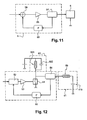
- Figure 11, une représentation schématique d'une boucle d'asservissement incluse dans l'amplificateur;
- Figure 12, une variante du système comprenant une boucle d'asservissement et des circuits de génération des premières oscillations de tension;
- Figure 13, une autre variante de système comprenant une boucle d'asservissement et des circuits de génération des premières oscillations de tension;
- Figure 14, un exemple de transformateur formant une sonde de courant de l'amplificateur, réalisé sur un circuit imprimé;
- Figure 15, un mode de réalisation d'une inductance parallèle sur un circuit imprimé;
- Figure 16, un autre mode de réalisation d'une inductance parallèle sur un circuit imprimé;
- Figure 17, une variante d'un système présentant une alimentation et un amplificateur communs pour deux résonateurs;
- Figures 18 et 19, des représentations schématiques en coupe d'un exemple de bougie utilisable dans le système de génération de plasma;
- Figures 20 à 27, différentes configurations de têtes de bougie adaptées pour une excitation radiofréquence.
- Figure 1, a diagram of operation of a spark plug surface spark;
- Figure 2, the representation of applied fields and the spark generated between the electrodes of the candle during ignition initiation;
- Figure 3, a diagram of the electrostatic field between the two electrodes of the candle during ignition initiation;
- Figure 4, a schematic representation of the development of a streamer for a single voltage rise (local field and global field);
- Figure 5 is a schematic representation of an embodiment of the plasma generating system according to the invention;
- Figure 6, an electric model used for the design of the series resonator;
- Figure 7, a variant in which the amplifier comprises a mid-point transformer;
- Figure 8, another variant of the system wherein the amplifier comprises a power transistor control by a bipolar transistor;
- Figure 9, timing of signals during the excitation of the resonator of Figure 7;
- Figure 10, the various elements of the power supply of Figure 7 integrated on the same circuit;
- Figure 11 is a schematic representation of a control loop included in the amplifier;
- 12, a variant of the system comprising a control loop and generating circuits of the first voltage oscillations;
- Figure 13, another system variant comprising a control loop and generating circuits of the first voltage oscillations;
- FIG. 14, an example of a transformer forming a current probe of the amplifier, produced on a printed circuit;
- Figure 15, an embodiment of a parallel inductance on a printed circuit;
- Figure 16, another embodiment of a parallel inductance on a printed circuit;
- Figure 17, a variant of a system having a common power supply and amplifier for two resonators;
- Figures 18 and 19, schematic sectional representations of an example of candle usable in the plasma generation system;
- Figures 20 to 27, various configurations of candle heads adapted for radio frequency excitation.
L'invention propose d'appliquer une tension alternative de fréquence supérieure à 1MHz et d'amplitude entre crêtes supérieure à 5 kV entre deux électrodes de génération de plasma, séparées par un élément en matériau diélectrique. Cette excitation sera désignée par la suite d'excitation radiofréquence. On génère ainsi un plasma de volume ou un plasma ramifié.The invention proposes to apply a voltage alternative of frequency higher than 1MHz and amplitude between peaks greater than 5 kV between two plasma generation electrodes, separated by a element made of dielectric material. This excitement will be referred to as the radiofrequency excitation suite. This generates a plasma of volume or a plasma branched.
La figure 1 illustre des détails de la structure d'une bougie d'allumage à étincelle de surface pour laquelle l'application d'une excitation radiofréquence s'avère particulièrement avantageuse. On va préalablement détailler le fonctionnement d'une telle bougie.Figure 1 illustrates details of the structure of a surface spark spark plug for which the application of a radiofrequency excitation is particularly advantageous. We go previously describe the operation of such candle.
La bougie à effet de surface 110 comprend une tête
de bougie destinée à déboucher dans la chambre de
combustion ménagée dans la paroi inférieure de la
culasse d'un moteur. La bougie comprend une électrode
cylindrique basse tension qui sert de culot métallique
103 destiné à se visser dans un évidement réalisé dans
la culasse du moteur et débouchant à l'intérieur de la
chambre de combustion. Le culot 103 est destiné à être
connecté électriquement à la masse.The
Le culot 103 entoure une électrode haute tension
cylindrique 106 disposée en position centrale.
L'électrode 106 est destinée à être reliée à un
générateur d'une haute tension d'allumage. L'électrode
106 est isolée du culot 103 par l'intermédiaire d'un
manchon isolant 100. Le manchon isolant est constitué
d'une matière dont la permittivité relative est
supérieure à 3, par exemple une céramique. La bougie
présente un espace 105 séparant le diélectrique 100 et
une extrémité de l'électrode 103.The
L'électrode 106 et le manchon isolant 100
débouchent en saillie d'une longueur 1 à l'extérieur du
culot 103. Cette longueur 1 correspond sensiblement à
la longueur de l'étincelle générée lorsqu'une haute
tension est appliquée entre les électrodes 106 et 103.The
Le culot ou électrode basse tension 103 comprend de
façon monobloc un corps et une pièce de liaison
supportant une collerette rabattue 101. La collerette
101 présente un bord biseauté s'étendant à proximité
immédiate de la surface de l'isolant 100.The base or
Le diélectrique 100 crée une amplification de champ
électrostatique dans l'air à son voisinage. L'étincelle
générée entre le bord biseauté de la collerette 101 du
culot 103 et une extrémité libre 104 de l'électrode
centrale 106 se propage à la surface de l'isolant 100,
là où le champ électrique dans l'air est le plus fort.The dielectric 100 creates a field amplification
electrostatic in the air in its vicinity. The spark
generated between the beveled edge of the
La formation d'une étincelle est initiée par
l'arrachement au milieu de quelques électrons soumis à
un champ électrique important. Lors de l'application
d'une tension importante entre les électrodes, des
électrons de la collerette sont accélérés par les
forces électrostatiques générées et heurtent des
molécules de l'air. L'extrémité de la collerette est la
zone qui subit le champ électrostatique le plus
important, et constitue donc le lieu de départ de la
première avalanche. Les molécules de l'air libèrent un
électron et un photon ionisant à leur tour d'autres
molécules d'air. Une réaction en chaíne ionise l'air
dans l'espace 105 entre l'électrode 103 et le
diélectrique 100. L'espace de gaz 105 permet de
réaliser une ionisation préalable avec une différence
de potentiel entre les électrodes 103 et 106
relativement limitée.The formation of a spark is initiated by
tearing in the middle of a few electrons subject to
an important electric field. When applying
significant voltage between the electrodes,
electrons of the collar are accelerated by the
electrostatic forces generated and strike
molecules of the air. The end of the collar is the
area that undergoes the most electrostatic field
important, and thus constitutes the starting point of the
first avalanche. The molecules of the air release a
electron and an ionizing photon in turn other
molecules of air. A chain reaction ionizes the air
in the
Un canal conducteur est ainsi créé, comme illustré
à la figure 2. Les lignes discontinues représentent des
équipotentielles du champ électrostatique lorsqu'une
tension élevée est appliquée entre les électrodes 103
et 106.A conductive channel is thus created, as illustrated
in Figure 2. The broken lines represent
equipotentials of the electrostatic field when a
high voltage is applied between the
La figure 3 représente un exemple d'amplitude de
champ électrostatique entre l'extrémité de la
collerette 101 et l'extrémité de l'électrode 106, A
désignant l'extrémité de la collerette, B désignant
l'extrémité 104 de l'électrode 106. Une fois que l'air
est ionisé au niveau de l'extrémité de la collerette,
l'ionisation de l'air crée une charge d'espace
présentant un potentiel proche de celui de la
collerette et qui se comporte donc comme un
prolongement de celle-ci. Lors de la propagation du
front d'avalanche, le champ électrique est amplifié en
amont du front et favorise la création de nouvelles
avalanches. Le phénomène s'auto-entretient le long du
manchon 100, pour créer un canal ionisé conducteur
jusqu'à l'extrémité 104 de l'électrode centrale.FIG. 3 represents an example of amplitude of
electrostatic field between the end of the
Dans la bougie de la figure 1, l'isolant est séparé
de l'électrode 103 par un espace d'air. Cet espace
n'est pas essentiel pour le fonctionnement de la bougie
mais facilite la fabrication de la bougie avec une
collerette présentant un angle très vif à proximité de
la surface de l'isolant. Il permet également de réduire
l'influence des phénomènes d'encrassement.In the candle of Figure 1, the insulation is separated
of the
Le phénomène physique mis en oeuvre grâce à l'excitation radiofréquence présente des similitudes avec la propagation décrite précédemment mais permet d'en améliorer considérablement les effets. La figure 4 représente schématiquement le champ électrostatique lors du départ d'une avalanche. On peut y remarquer que la propagation de l'avalanche est limitée par le champ local dû à la séparation des atomes et de leurs électrons. Ce champ local limite en particulier la propagation de la décharge sur des longueurs importantes. La présente invention propose, entre autres, une excitation électrique capable d'inverser la polarité du champ global imposé avant que les électrons n'aient pu se recombiner avec les atomes présents dans le milieu. A chaque alternance de la polarité, les électrons sont de plus en plus accélérés en sens inverse. Une onde de polarisation se propage ainsi de manière oscillatoire à la fréquence de l'excitation, récupérant à chaque période les charges déposées à la période précédente. Chaque alternance produit alors une propagation de l'onde plus importante que la précédente; il est ainsi possible d'obtenir des étincelles de longueurs très importantes avec des amplitudes de tensions entre les électrodes relativement limitées. L'excitation radiofréquence supprime également les variations de tension de claquage entre des cycles successifs.The physical phenomenon implemented thanks to radiofrequency excitation has similarities with the propagation described above but allows significantly improve the effects. Figure 4 schematically represents the electrostatic field when leaving an avalanche. We can notice that Avalanche propagation is limited by the field locality due to the separation of atoms and their electrons. This local field limits in particular the spread of the discharge over lengths important. The present invention proposes, other, an electrical excitation capable of reversing the polarity of the global field imposed before the electrons could not recombine with the atoms present in the middle. With each alternation of polarity, the electrons are becoming more and more accelerated in sense reverse. A polarization wave propagates thus oscillatory way at the frequency of the excitation, recovering at each period the charges deposited at the previous period. Each alternation then produces a wave propagation larger than the previous; it is thus possible to obtain sparks of very long lengths with voltage amplitudes between the electrodes relatively limited. Radio frequency excitation also removes voltage variations from breakdown between successive cycles.
Pour une application à l'allumage automobile, l'homme de métier utilisera des électrodes et un isolant présentant des matériaux et une géométrie adéquats pour initier une combustion dans un mélange à une densité de combustion et pour résister au plasma ainsi formé.For an application to automotive ignition, the skilled person will use electrodes and a insulation showing materials and geometry suitable for initiating combustion in a mixture with a density of combustion and to resist the plasma thus formed.
Un plasma ainsi formé présente de nombreux intérêts dans le cadre de l'allumage automobile: diminution sensible du taux de ratés dans un système à mélange pauvre stratifié, réduction de l'usure des électrodes et adaptation du volume d'initiation de l'allumage en fonction de la densité. On constate que l'excitation décrite est adaptée pour réaliser l'allumage d'un mélange présentant une densité supérieure à 5*10-2 mol/L. Pour cette application d'allumage, le générateur applique l'excitation entre 1,5 et 200 fois par secondes, avec un rapport cyclique d'application compris entre 10 et 1000, et de préférence compris entre 72 et 720.Plasma thus formed has many advantages in the context of automotive ignition: significant reduction in the rate of misfires in a stratified lean mixture system, reduction of wear of the electrodes and adaptation of the ignition initiation volume to density function. It is found that the excitation described is adapted to achieve ignition of a mixture having a density greater than 5 * 10 -2 mol / L. For this ignition application, the generator applies the excitation between 1.5 and 200 times per second, with an application duty ratio of between 10 and 1000, and preferably between 72 and 720.
L'excitation radiofréquence décrite est également adaptée à une application de dépôt plasma, dans un gaz présentant une densité comprise entre 10-2 mol/L et 5*10-2 mol/L. Le gaz utilisé dans cette application peut typiquement être de l'azote.The radiofrequency excitation described is also adapted to a plasma deposition application in a gas having a density of between 10 -2 mol / L and 5 * 10 -2 mol / L. The gas used in this application may typically be nitrogen.
L'excitation radiofréquence est encore adaptée à une application de dépollution d'un gaz présentant une densité comprise entre 10-2 mol/L et 5*10-2 mol/L.The radiofrequency excitation is further adapted to an application for the depollution of a gas having a density of between 10 -2 mol / L and 5 * 10 -2 mol / L.
L'excitation radiofréquence est en outre adaptée à une application d'éclairage faisant appel à un gaz présentant une densité molaire comprise entre 0,2 mol/L et 1 mol/L.The radiofrequency excitation is further adapted to a lighting application using a gas having a molar density of between 0.2 mol / L and 1 mol / L.
Un système de génération de plasma envisagé comprend principalement trois sous-ensembles fonctionnels:
- un générateur capable de faire résonner une structure L-C à une fréquence supérieure à 1MHz avec une tension aux bornes du condensateur supérieure à 5kV, de préférence supérieure à 6kV.
- un résonateur connecté en sortie du générateur et présentant un facteur de surtension compris entre 40 et 200 et présentant une fréquence de résonance supérieure à 1 MHz.
- une tête de bougie comprenant deux électrodes séparées par un isolant, permettant de générer un plasma lors de l'application de l'excitation radiofréquence.
- a generator capable of resonating an LC structure at a frequency greater than 1 MHz with a voltage across the capacitor greater than 5 kV, preferably greater than 6 kV.
- a resonator connected at the output of the generator and having an overvoltage factor between 40 and 200 and having a resonance frequency greater than 1 MHz.
- a candle head comprising two electrodes separated by an insulator, for generating a plasma during the application of the radiofrequency excitation.
La figure 5 représente un mode de réalisation d'un système de génération de plasma 1 et de son générateur de tension 2. Le générateur de tension comprend avantageusement :
- une alimentation basse tension 3 (générant une tension continue inférieure à 1000 V);
un amplificateur radiofréquence 5, amplifiant la tension continue et générant une tension alternative à la fréquence commandée par la commande decommutation 4.
- a low voltage supply 3 (generating a DC voltage of less than 1000 V);
- a
radio frequency amplifier 5, amplifying the DC voltage and generating an AC voltage at the frequency controlled by the switchingcontrol 4.
La tension alternative de l'amplificateur 5 est
appliquée sur le résonateur LC 6. Le résonateur LC 6
applique la tension alternative selon l'invention entre
les électrodes 103 et 106 de la tête de bougie.The AC voltage of the
La tension fournie par l'alimentation 3 est
inférieure à 1000V et l'alimentation présente de
préférence une puissance limitée. On peut ainsi prévoir
que l'énergie appliquée entre les électrodes soit
limitée à 300mJ par allumage, pour des raisons de
sécurité. On bride ainsi également l'intensité dans le
générateur de tension 2 et sa consommation électrique.
Pour générer des tensions continues supérieures à 12 V
dans une application automobile, l'alimentation 3 peut
comprendre un convertisseur 12 Volt vers Y Volt, Y
étant la tension fournie par l'alimentation à
l'amplificateur. On peut ainsi générer le niveau de
tension continue souhaitée à partir d'une tension de
batterie. La stabilité de la tension continue générée
n'étant a priori pas un critère déterminant, on peut
prévoir d'utiliser une alimentation à découpage pour
alimenter l'amplificateur, pour ses qualités de
robustesse et de simplicité.The voltage supplied by the power supply 3 is
less than 1000V and the power supply presents
preferably a limited power. We can thus foresee
that the energy applied between the electrodes is
limited to 300mJ per ignition, for reasons of
security. We also restrict the intensity in the
On peut également envisager, selon une variante,
d'appliquer aux bornes de l'amplificateur une tension
de 42 V prélevée sur le circuit électrique du véhicule.
Il s'agit en effet du niveau de tension qui sera en
vigueur dans de futures normes applicables aux futurs
véhicules automobiles. Cette variante, évitant la
conversion de tension par l'alimentation 3, réduit
sensiblement le coût et la complexité du générateur de
tension 2.One can also envisage, according to a variant,
to apply to the terminals of the amplifier a voltage
42 V taken from the vehicle's electrical circuit.
This is indeed the level of tension that will be
in future future standards
motor vehicles. This variant, avoiding the
voltage conversion through the power supply 3, reduced
substantially the cost and complexity of the generator of
Ce générateur de tension permet de concentrer les
tensions les plus élevées sur le résonateur 6.
L'amplificateur 5 traite ainsi des tensions beaucoup
plus réduites que les tensions appliquées entre les
électrodes: on peut donc utiliser un amplificateur 5
d'un coût raisonnable et présentant des
caractéristiques voisines de composants usuels pour la
production automobile de masse, dont la fiabilité est
en outre éprouvée. De plus, un tel générateur de
tension présente un nombre de composants relativement
réduit. On dispose ainsi d'un système de génération de
tension présentant une fiabilité, un volume, un poids
et une facilité de production intéréssants, en
particulier pour de grandes séries dans une application
automobile.This voltage generator helps to focus the
highest voltages on the
L'amplificateur 5 permet d'accumuler de l'énergie
dans le résonateur 6 à chaque alternance de sa tension.
On utilisera de préférence un amplificateur 5 en classe
E, tel que détaillé dans le brevet US-5 187 580. Un tel
amplificateur permet de maximiser le facteur de
surtension. Un tel amplificateur réalise des
commutations déphasées par rapport à l'amplificateur
décrit dans le brevet US-3 919 656 qui vise à réaliser
des commutations à tension et/ou intensités nulles et
n'optimise pas le facteur de surtension de
l'amplificateur. L'homme de métier associera bien
entendu un dispositif de commutation adapté à
l'amplificateur choisi, pour supporter les exigences de
montées en tension et présenter une vitesse de
commutation adéquate.The
L'amplificateur en classe E préférentiel comporte
un résonateur parallèle 62. Ce résonateur parallèle 62
est de préférence réalisé sur la même carte que
l'amplificateur 5 et sa commande 4 de commutation. Le
résonateur parallèle 62 stocke temporairement de
l'énergie fournie par l'amplificateur 5, et fournit
périodiquement cette énergie au résonateur série 61.
Avec les valeurs de tension d'alimentation précisées
par ailleurs, on utilisera un amplificateur 5
présentant un coefficient de surtension de l'ordre de
3. Ce coefficient de surtension correspond au rapport
entre la tension fournie par l'alimentation basse
tension 3 et l'amplitude entre crêtes de la tension
appliquée sur le résonateur série. Le coefficient de
surtension du résonateur série 61 associé est alors de
préférence compris entre 40 et 200. Le coefficient de
surtension du résonateur série est notamment limité par
son angle de perte.The preferred class E amplifier features
a
On va exposer un dimensionnement préférentiel des
éléments inductifs et capacitifs du résonateur série
61. La figure 6 illustre un modèle électrique de ce
résonateur. Ainsi, l'inductance série 65 présente en
série une inductance L et une résistance Rs prenant en
compte l'effet de peau dans le domaine radiofréquence.
Le condensateur 119 présente en parallèle une capacité
C et une résistance Rp. La résistance Rp correspond le
cas échéant à la dissipation dans la céramique de la
bougie. Lorsque le résonateur série 61 est alimenté par
une tension à sa fréquence de résonance f0
(1/(2π√(L*C))), l'amplitude aux bornes de la capacité C
est amplifiée du coefficient de surtension Q défini par
la formule suivante:
De l'équation ω0 2= (2π*f0)2=1/ (L*C), on déduit que
l'équation suivante doit être vérifiée pour obtenir la
valeur maximale de Q:
On va prendre en compte les conditions suivantes:
- f0 est de l'ordre de 5MHz;
- les valeurs Rs et Rp sont constantes;
- Rp est principalement induite par l'encrassement de la tête de bougie et vaut en moyenne 50 kQ;
- Rs vaut approximativement 10 Ω en prenant en compte l'effet de peau.
- f 0 is of the order of 5 MHz;
- the values Rs and Rp are constant;
- Rp is mainly induced by the fouling of the candle head and is worth on average 50 kQ;
- Rs is approximately 10 Ω taking into account the skin effect.
On déduit alors
Une autre modélisation permet également de déterminer ces caractéristiques. La résistance de la capacité est modélisée par le facteur de dissipation diélectrique (tan (δ)=1/(Rp*C)) dans le matériau isolant de la tête de bougie, que l'on considère constant et uniquement dépendant du matériau choisi.Another modeling also allows determine these characteristics. The resistance of the capacity is modeled by the dissipation factor dielectric (tan (δ) = 1 / (Rp * C)) in the material insulation of the candle head, which is considered constant and solely dependent on the chosen material.
Le coefficient de surtension est alors défini comme
suit:
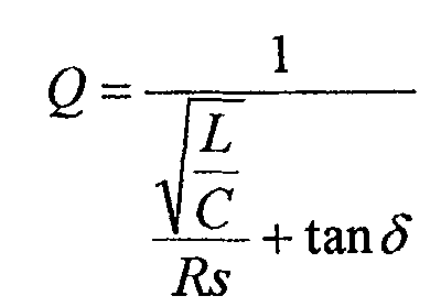
La maximisation du coefficient de surtension Q est
alors équivalente à la minimisation de
Ces règles de détermination s'appliquent quel que soit le type de résonateur série utilisé et s'appliquent donc également à la bobine-bougie décrite ultérieurement.These determination rules apply regardless of the type of series resonator used and therefore also apply to the described coil-candle later.
Un compromis dans le choix des valeurs est cependant nécessaire pour la variante utilisant un transistor MOS de puissance comme interrupteur, comme décrit ci-après. En effet, le courant traversant l'interrupteur MOS croit alors avec la capacité C. La valeur de la capacité C doit donc être fixée en fonction du courant nominal de l'interrupteur MOS.A compromise in the choice of values is however necessary for the variant using a MOS transistor power as a switch, as described below. Indeed, the current through the MOS switch then increases with the capacity C. value of the capacitance C must therefore be fixed in function of the nominal current of the MOS switch.
On va maintenant décrire plusieurs variantes
d'amplificateurs 5. De façon générale, on utilisera de
préférence un amplificateur présentant un transistor
MOSFET de puissance comme interrupteur 51 commandant
les commutations aux bornes du résonateur 6. Les
figures 7 et 8 illustrent deux modes de réalisations
d'amplificateurs 5 incluant des MOSFET M4, comme
interrupteurs 51. Les contraintes d'amplitude et de
fréquence concernant la tension à générer entre les
électrodes peuvent être résolues avec un transistor
MOSFET de puissance présentant les caractéristiques
suivantes: une isolation supérieure à 500 V, une
capacité en courant de drain supérieure à 30 A, un
temps de commutation inférieur à 20 ns (et de
préférence de l'ordre de 10ns en cas d'utilisation
d'une boucle d'asservissement) et une capacité en
courant de grille atteignant 10A.We will now describe
Ce transistor MOSFET présentera également de préférence une inductance inférieure à 7 nH sur ses liaisons entre sa surface active de silicium et le circuit imprimé sur lequel il est implanté. On évite ainsi des transitoires lors de pics de tension élevés qui seraient préjudiciables aux commutations rapides du transistor. This MOSFET transistor will also present preferably an inductance of less than 7 nH on its connections between its active silicon surface and the circuit board on which it is implanted. We avoid thus transients during high voltage peaks which would be detrimental to the rapid switching of the transistor.
La figure 7 représente un premier mode de
réalisation d'un amplificateur 5 présentant un tel
transistor de commande de commutation M4. Un
transformateur à point milieu 56 est interposé entre la
commande 4 et le MOSFET de puissance M4. Le MOSFET de
puissance M4 peut ainsi être commandé très rapidement
avec une tension symétrique capable de le bloquer
efficacement. En effet, l'application d'une tension
négative sur la grille du transistor MOSFET M4 permet
de compenser les surtensions causées par l'inductance
de liaison de M4 avec le reste du circuit. Le blocage
du transistor est ainsi facilité, d'autant qu'une
tension négative permet de décharger la capacité
grille-drain particulièrement rapidement.Figure 7 shows a first mode of
realization of an
L'amplificateur 5 représenté comprend deux
transistors intermédiaires M1 et M2 disposés pour
alimenter en alternance les bobines L1 et L2 du
primaire du transformateur à point milieu. Un circuit
de pilotage 57 applique des signaux de commande
respectifs sur les transistors M1 et M2. Les signaux de
commande ne se recouvrent pas temporellement pour
éviter un court-circuit dans le primaire. Les signaux
de commande présentent également avantageusement des
durées d'activation sensiblement égales pour limiter le
courant magnétisant dans le transformateur 56. On peut
également compenser une inégalité des temps
d'activation par une valeur élevée de l'inductance
magnétisante du transformateur 56. The
Le chronogramme de la figure 9 illustre différents
signaux durant l'excitation du résonateur série 61. La
courbe 91 représente le courant traversant le
résonateur série 61. La courbe 92 illustre la tension
de grille du MOSFET M4. La courbe 93 illustre la
tension à l'entrée du résonateur série 61.The timing diagram in Figure 9 illustrates different
signals during the excitation of the
On intègre avantageusement l'amplificateur 5 sur un
même circuit imprimé 8. On peut ainsi intégrer le
transformateur 56, les transistors M1 à M4 et le
circuit de pilotage 57 sur le même circuit imprimé,
selon le schéma représenté à la figure 10. On obtient
ainsi pour un coût réduit un amplificateur 5 très
compact. On minimise également l'inductance de fuite du
transformateur et les surtensions aux bornes des
transistors intermédiaires M1 et M2.The
La partie gauche de la figure 10 représente
plusieurs éléments de l'amplificateur 5 et leurs
connexions. La partie centrale de la figure 10
représente les transistors M1 et M2 et leur bobinage
respectif L11 et L12. La partie droite de la figure 10
représente schématiquement les différents éléments
intégrés sur le circuit imprimé 8. L'ensemble formé par
les transistors M1 à M4, les bobines L11, L12 et L2,
est de préférence disposé sur un bord du circuit
imprimé 8. Les bobinages peuvent ainsi être disposés
dans l'entrefer d'un tore fendu 81.The left part of Figure 10 represents
several elements of the
La figure 8 représente un second mode de
réalisation d'un amplificateur 5 présentant un
transistor de commande de commutation MOSFET M4. Les
grilles des transistors M1 et M2 sont liées. Les
transistors M1 et M2 commutent donc simultanément. Le
transistor bipolaire M3 est donc monté en suiveur.
Lorsque M1 et M2 conduisent, le transistor bipolaire M3
est bloqué, et par conséquent, le transistor MOSFET M4
est également bloqué. On utilisera de préférence des
transistors intermédiaires M1 et M2 présentant les
caractéristiques suivantes: Une tension de commande de
5V, une intensité nominale de 8A à cette tension, une
résistance Ron inférieure à 150 milliOhms et un temps de
réponse inférieur à 20ns.FIG. 8 represents a second embodiment of an
Comme représenté aux figures 11 à 13, on réalise
avantageusement un asservissement de l'amplificateur 5
sur le courant de charge appliqué au résonateur 6. En
pratique, on cherche à asservir un interrupteur 51
commandant les commutations aux bornes du résonateur 6.
L'amplificateur 5 présente ainsi un dispositif de
mesure 54 du courant appliqué à l'entrée du résonateur
6. La consigne est appliquée sur une entrée 58 d'un
comparateur. Le signal de sortie du comparateur est
appliqué sur un dispositif d'amplification 53
représenté schématiquement. On optimise ainsi le
facteur de surtension de l'amplificateur 5 en pilotant
le résonateur 6 à sa fréquence propre malgré les
dérives de comportement des composants. On évite ainsi
de recourir à des composants dont le coût et la
complexité sont inappropriés à une production de masse.
L'asservissement est par exemple réalisé en réinjectant
dans l'amplificateur 5 une tension proportionnelle au
courant circulant dans la charge. On peut également
appliquer une correction de phase sur le signal mesuré
par l'intermédiaire du module de déphasage 55.As shown in FIGS. 11 to 13,
advantageously a
Dans un tel transformateur 54, combiné à une boucle
d'asservissement, la résistance parallèle R2 du
secondaire du transformateur remplit préférentiellement
deux fonctions de l'asservissement: la rétroaction d'un
signal proportionnel au courant dans la charge, et le
déphasage de l'intensité traversant la charge en
fonction de sa valeur de résistance.In such a
On utilise avantageusement un transformateur 54
présentant une valeur d'inductance très réduite (par
exemple comprise entre 10 et 20 nH) et dont les
enroulements supportent un courant de l'ordre de 10A.
La figure 14 présente ainsi un exemple de
transformateur réalisé sur un circuit imprimé,
facilitant l'obtention de telles caractéristiques. La
partie gauche de la figure 14 représente indépendamment
les couches utiles du circuit imprimé. La partie droite
de la figure représente ces couches superposées et
assemblées. L'élément conducteur 151 forme le primaire
d'un transformateur, et est disposé sur une première
face du substrat 152. Cet élément conducteur 151 est
dans l'exemple réalisé sous forme sensiblement filaire.
Les éléments conducteurs 153 et 154 forment le
secondaire du transformateur. Ces éléments conducteurs
153 et 154 sont disposés sur une deuxième face du
substrat 152, en vis-à-vis de l'élément conducteur 152.
Les éléments 153 et 154 sont reliés électriquement
d'une part suivant la ligne pointillée, et d'autre part
par la résistance 155. La résistance 155 peut ainsi
être utilisée pour mesurer le courant traversant
l'élément conducteur 151 et pour former le module de
déphasage 55 décrit précédemment.It is advantageous to use a
On adapte avantageusement l'asservissement de
l'interrupteur 51 commandant les commutations aux
bornes du résonateur 6 décrit précédemment aux modes de
réalisations présentant un transistor de commande de
commutation MOSFET de puissance comme interrupteur. On
peut ainsi commuter le transistor MOSFET M4 aux
instants optimaux.Advantageously adapts the servocontrol of
the
Afin que la structure d'asservissement produise rapidement des oscillations, malgré un courant de charge initial nul, on dispose de plusieurs variantes avantageuses du système.In order for the servo structure to produce quickly oscillations, despite a current of zero initial charge, there are several variants advantages of the system.
Le résonateur LC 6 comprend un résonateur série 61
et un résonateur parallèle 62. Le résonateur série 61
présente une capacité série 119 et une inductance série
65. Selon une première variante, la structure
d'asservissement comprend un oscillateur astable 52
(par exemple un générateur de créneaux) pour générer
les premières alternances dans la capacité série 119 et
stabiliser les oscillations en régime entretenu. On
prévoit que la fréquence de l'oscillateur soit proche
de la fréquence de l'excitation générée entre les
électrodes. La structure d'asservissement additionne le
signal de mesure de courant et le signal de
l'oscillateur astable 52 et permet ainsi à
l'amplificateur en classe E de réaliser les
commutations aux moments les plus favorables.
Par ailleurs, le premier créneau généré par
l'oscillateur 52 est approximativement deux fois plus
court que les suivants : ainsi, on peut initialiser le
courant dans l'inductance série 65 à la valeur de ce
courant en régime entretenu. Le résonateur parallèle 62
comprend une inductance 621 et une capacité 622
disposées en parallèle. Toutes les impulsions aux
bornes de l'inductance 621 et de la capacité 622 sont
alors égales. On peut ainsi éviter de sur-dimensionner
l'interrupteur 51 et l'exploiter de façon optimale.In addition, the first niche generated by
the
La figure 12 représente une seconde variante. Le
signal de commande appliqué sur l'interrupteur 51
génère un créneau de tension de faible durée, c'est-à-dire
de l'ordre de 5µs, initiant la première alternance
dans le résonateur 6. Le signal d'asservissement
commande ensuite l'interrupteur 51. La boucle de
rétroaction de la structure d'asservissement présente
un gain élevé. Ainsi, l'impulsion initiale rendant
l'asservissement opérationnel est suffisamment courte,
et le courant traversant l'interrupteur 51 reste
raisonnable. Il n'est ainsi pas nécessaire de sur-dimensionner
l'interrupteur 51 pour réaliser le
démarrage de l'asservissement, en particulier lorsque
l'interrupteur est formé d'un transistor MOSFET de
puissance.Figure 12 shows a second variant. The
control signal applied to the
Une combinaison avantageuse du résonateur parallèle
62 et du résonateur série 61 optimise le fonctionnement
du système lorsque la fréquence propre du résonateur
parallèle 62 est légèrement supérieure à celle du
résonateur série 61. Ainsi, l'impulsion de tension
générée par la fermeture du transistor interrupteur M4
a une durée inférieure à la demi-période du résonateur
série 61. Ainsi, l'impulsion lors de la fermeture du
transistor interrupteur M4 est anticipée par la diode
inverse interne du transistor M4 lorsque la tension de
son drain repasse par une valeur nulle. On prévoit
alors que le rapport entre les impédances
caractéristiques respectives du résonateur parallèle 62
et du résonateur série 61 soit inférieur à 100
supérieur à 40. La valeur inférieure garantit un bon
coefficient de surtension. La valeur supérieure limite
les courants dans le transistor M4. On utilise
typiquement une capacité de 1 nF et une inductance de 1
µH pour le résonateur parallèle 62. L'impédance
caractéristique du résonateur parallèle 62 vaut alors
approximativement 32 ohms.An advantageous combination of the
Par ailleurs, dans le résonateur parallèle 62, on
peut considérer que les capacités entre les spires de
l'inductance 621 seront négligeables par rapport à la
capacité du condensateur 622. On peut donc réaliser
l'inductance 621 sous forme d'une superposition de
pistes conductrices 623 sensiblement circulaires,
réalisées sur les couches superposées d'un circuit
imprimé. Des exemples de structures d'inductances 621
sur circuit imprimé sont représentés aux figures 15 et
16. Les modes de réalisation de ces figures permettent
ainsi de réaliser une inductance 621 sans noyau de
ferrite. On réduit ainsi le coût et on améliore les
performances de l'inductance 621.Moreover, in the
Sur les figures 15 et 16, les points épais
représentent des plots de connexion des différentes
pistes. Les traits verticaux joignant les plots de
connexion représentent des liaisons conductrices entre
les plots. Les pistes connectées forment ainsi une
bobine. Avantageusement, chaque piste 623 est entourée
d'une boucle fermée 625, afin de réduire le rayonnement
de l'inductance 621 formée par les pistes.In Figures 15 and 16, the thick dots
represent connection pads of different
tracks. The vertical lines joining the studs
connection represent conductive links between
the studs. The connected tracks thus form a
coil. Advantageously, each
Le schéma de la figure 15 représente une variante
présentant une couche supérieure et une couche
inférieure ne présentant pas de piste de bobine. La
couche supérieure et la couche inférieure présentent
chacune une borne de connexion 624 de l'inductance 621.The diagram of FIG. 15 represents a variant
having a top layer and a layer
lower that does not have a coil track. The
upper layer and the lower layer present
each a
Le schéma de la figure 16 représente une variante,
dans laquelle la couche inférieure et la couche
supérieure présentent chacune une piste de bobine et
une borne de connexion. Les lignes courbes 626 joignant
un plot de connexion à une borne de connexion 624
représentent une liaison électrique rapportée sur ces
couches de circuit imprimé.The diagram of FIG. 16 represents a variant,
in which the lower layer and the layer
each have a coil track and
a connection terminal.
Aux fréquences de travail du résonateur 6, les
pertes sont importantes. Afin de limiter ces pertes, on
limite de préférence au maximum la présence de matériau
magnétique dans le résonateur série 61.At the working frequencies of the
Il est à noter dans ce qui précède que la mention d'un résonateur série n'implique pas forcément que le résonateur inclut également un résonateur parallèle. It should be noted in the foregoing that the reference of a series resonator does not necessarily imply that the resonator also includes a parallel resonator.
Comme illustré à la figure 17, on peut envisager
une variante, dans laquelle on utilise une alimentation
et un amplificateur communs pour deux résonateurs 6
disposés en parallèle. Cette variante permet de
réduire le poids, le coût et la complexité globale du
système de génération de tension 1 pour un moteur à
allumage commandé. Chaque résonateur 6 correspond à une
chambre de combustion respective 141 et 142, les deux
chambres de combustion étant en opposition de phase.
L'amplificateur 5 est commandé de sorte que la tension
d'allumage soit générée à la fois lors de la
compression et lors de la détente pour chaque chambre
de combustion. En effet, la compression dans une
chambre 141 est synchronisée avec la détente 142 dans
l'autre. Lors de la génération de la tension, le
claquage dans la chambre en détente 142 est beaucoup
plus rapide que dans la chambre en compression 141. En
effet, la densité de gaz dans la chambre en détente est
beaucoup plus faible que la densité dans la chambre en
compression. La résistance de décharge équivalente de
la chambre en détente 142 est ainsi beaucoup plus
élevée que celle de la chambre en compression. La
bougie présente dans la chambre en compression poursuit
alors sa montée en tension jusqu'au claquage. La
densité du gaz dans la chambre en détente est
suffisamment faible pour ne pas modifier de façon
gênante le coefficient de surtension dans la chambre en
compression; la génération de l'étincelle dans la
chambre en compression est ainsi peu perturbée par la
génération de la tension dans l'autre chambre.As shown in Figure 17, we can consider
a variant, in which a power supply is used
and a common amplifier for two
La figure 18 représente une vue en coupe d'une
bougie intégrant avantageusement un résonateur série
61. La bougie 110 présente une borne de connexion 131,
connectée à une première extrémité d'un bobinage
inductif 112. La deuxième extrémité du bobinage
inductif 112 est connectée à une extrémité interne de
l'électrode haute tension 106. Cette extrémité est
également en contact avec un élément isolant 111
formant le condensateur.Figure 18 shows a sectional view of a
candle advantageously integrating a
Les électrodes 103 et 106 sont dans cet exemple
séparées par le matériau diélectrique 100 destiné au
guidage des étincelles entre ces électrodes. Le
résonateur série 61 intégré dans la bougie 110 comprend
le bobinage inductif 112 et l'élément isolant 100
formant également le condensateur entre les électrodes
103 et 106. Le condensateur et le bobinage inductif 112
sont disposés en série. La capacité série du résonateur
série 61 est formée du condensateur et des capacités
parasites internes de la bougie. Cette capacité 119 est
disposée en série avec une inductance 65 pour former le
résonateur série 61. La longueur de la connexion entre
l'inductance et le condensateur étant ainsi réduite, on
réduit les capacités parasites dans la bougie. Il est
ainsi aisé d'obtenir un coefficient de surtension du
résonateur série compris dans la plage préférentielle
de 40 à 200 décrite précédemment. La bougie 110 est
ainsi utilisée pour entretenir la tension alternative
entre les électrodes 103 et 106, dans le domaine de
fréquence souhaité.The
Le résonateur série intégré dans la bougie présente de préférence un bobinage unique 112, facilitant la fabrication d'une telle bougie.The series resonator built into the present candle preferably a single winding 112, facilitating the making such a candle.
Un nombre important de spires dans le bobinage
unique 112 est nécessaire pour obtenir une inductance
de l'ordre de 50 µH (ordre de grandeur détaillé par la
suite). Or, un nombre de spires important génère des
capacités parasites. L'unique bobinage inductif 112
présente de préférence un axe (identifié par la ligne
en trait mixte) et est constitué d'une pluralité de
spires superposées suivant son axe. On entend ainsi que
la projection d'une spire est identique à la projection
de toutes les spires suivant cet axe. On limite alors
les capacités parasites en ne superposant pas des
spires radialement.A large number of turns in the winding
unique 112 is necessary to obtain an inductance
of the order of 50 μH (order of magnitude detailed by the
after). However, a large number of turns generates
stray capacitances. The only
La bougie comprend en outre avantageusement un
blindage 132 connecté à une masse et entourant le
bobinage inductif 112. Les lignes de champ sont ainsi
refermées à l'intérieur du blindage 132. Le blindage
132 réduit ainsi les émissions électromagnétiques
parasites de la bougie 110. Le bobinage 112 peut en
effet générer des champs électromagnétiques intenses
avec l'excitation radiofréquence qu'il est envisagé
d'appliquer entre les électrodes. Ces champs peuvent
notamment perturber des systèmes embarqués d'un
véhicule ou dépasser des seuils définis dans des normes
d'émission. Le blindage 132 est de préférence constitué
d'un matériau non ferreux à conductivité élevée, tel
que le cuivre. On peut notamment utiliser une boucle
conductrice comme blindage 132.The candle furthermore advantageously comprises a
shielding 132 connected to a mass and surrounding the
inductive winding 112. The field lines are thus
closed within shielding 132. Shielding
132 thus reduces electromagnetic emissions
parasite of the
Pour un blindage 132 et un bobinage unique 112
présentant chacun une forme globalement cylindrique, le
rapport optimal entre leur diamètre vaut le nombre
d'Euler, soit approximativement 2,72, si l'on veut
minimiser le champ électrique maximal, généré à la
surface des spires. On évite ainsi des phénomènes de
claquage à l'origine de dissipations d'énergie dans la
bougie. On choisira alors de préférence un rapport
entre leur diamètre compris entre 2,45 et 3.For a 132 shield and a
L'utilisation de deux bobinages 112 enroulés l'un
sur l'autre et connectés en parallèle permet de réduire
la résistance du bobinage formé. L'effet de peau,
augmentant de façon importante la résistance du
bobinage dans le domaine radiofréquence, est minimisé
par l'enroulement l'un sur l'autre de ces deux
bobinages. Si l'on veut minimiser la longueur du
bobinage 112 pour une inductance prédéterminée, le
rapport optimal entre le diamètre du blindage 132 et le
bobinage 112 vaut
Le bobinage 112 et le blindage 132 sont de
préférence séparés par un manchon d'isolation 133 en un
matériau diélectrique approprié, afin de réduire encore
le risque de claquage ou d'effluve, à l'origine de
dissipations d'énergie. Bien entendu, plus les
dissipations d'énergie sont faibles, plus l'amplitude
de la tension appliquée entre les électrodes est élevée
et plus la durée de vie de la bougie est élevée. Le
matériau diélectrique peut par exemple être une des
résines silicones commercialisées sous les références
Elastosil M4601, Elastosil RTV-2 ou Elastosil RT622
(cette dernière présentant une tension de claquage de
25 kV/mm et une constante diélectrique de 2,8). On peut
prévoir que la surface extérieure du manchon 133 soit
métallisée pour constituer le blindage 132 précité.The
De façon générale, on privilégiera un enroulement
du bobinage 112 autour d'un élément plein 134 réalisé
en matériau isolant et amagnétique. On réduit ainsi
encore les risques de claquage et les capacités
parasites.In general, we will favor a winding
winding 112 around a
L'ensemble des matériaux diélectriques est de préférence fortement débullé, afin de réduire encore les risques de claquage. L'ensemble des matériaux diélectriques de la bougie présente de préférence des températures de fusion supérieures à 150 °C. The set of dielectric materials is preference strongly debulled, in order to further reduce the risks of breakdown. All materials dielectric of the candle preferably has melting temperatures above 150 ° C.
De façon générale, lorsque la bobine-bougie
comprend plusieurs éléments isolants accolés, il existe
un risque non négligeable de créer des inclusions d'air
à l'interface entre ces éléments, notamment lorsqu'ils
sont réalisés en céramique. Or, pour des raisons
constructives, il est envisagé que la bobine-bougie
comprenne dans la plupart des cas plusieurs éléments
isolants accolés. En particulier, la liaison entre
l'isolant 134 de la bobine et l'isolant 111 de la tête
de bougie constitue également, pour les mêmes raisons
d'effluve, une source de dissipation très importante.
La technique précédemment citée peut, selon un nouveau
mode de réalisation, être mise à profit au niveau de la
céramique pour créer des équipotentielles prévenant la
formation de décharges électriques.Generally, when the coil-candle
includes several insulating elements contiguous, it exists
a significant risk of creating air inclusions
at the interface between these elements, especially
are made of ceramic. However, for reasons
constructive, it is envisaged that the coil-candle
in most cases understands several elements
contiguous insulators. In particular, the link between
the
La figure 19 représente une section d'un élément
isolant 111 de tête de bougie, résolvant également ce
problème. Cet élément isolant 111 est prévu pour être
associé à un élément isolant 133 sous forme de résine
de silicone. Cet élément isolant 111 présente une
section non circulaire et est inclus dans une pièce
circulaire 136 appartenant à la cathode 103. Ainsi, cet
élément forme des passages destinés à laisser fluer la
résine silicone lors de son injection. La résine
silicone peut ainsi éliminer la majeure partie des
inclusions d'air de la surface des éléments isolants.Figure 19 shows a section of an
Le matériau diélectrique utilisé pour l'isolant 100
peut par exemple être une céramique à base d'alumine,
de nitrure d'aluminium, d'oxyde d'aluminium ou de
carbure de silicium. The dielectric material used for the
Aux fréquences de travail du résonateur série, les pertes sont importantes. Afin de limiter ces pertes, l'homme de métier limitera au maximum la présence de matériau magnétique dans le résonateur série.At the working frequencies of the series resonator, the losses are important. In order to limit these losses, the skilled person will limit to the maximum the presence of magnetic material in the series resonator.
Selon une variante particulièrement avantageuse
illustrée à la figure 18, la bougie 110 présente en
outre un enroulement de mesure de courant 139
remplissant la fonction du module 54. Cet enroulement
139 comprend plusieurs spires entourant le bobinage
112. L'enroulement 139 est de préférence disposé à
proximité du connecteur 131 et à distance de la tête de
bougie, dans une zone où les tensions sont relativement
basses.According to a particularly advantageous variant
illustrated in Figure 18, the
La bougie de l'invention peut intégrer un certain
nombre d'autres caractéristiques, comme le joint de
siège 130 de la figure 18 disposé contre un épaulement
de la cathode 103, et destiné à assurer l'étanchéité de
la culasse au niveau de la lumière de la bougie.The candle of the invention can integrate a certain
number of other features, such as the seal of
La tête de bougie est la partie de la bougie qui
est placée dans le gaz dans lequel le plasma doit être
formé. Cette tête de bougie comprend préférentiellement
trois éléments: une électrode centrale 106, une
électrode de masse 103 et un isolant 100. La géométrie
de ces éléments est déterminante pour assurer la
formation du plasma de volume ou du plasma ramifié à
l'emplacement souhaité de la chambre, avec les
propriétés optimales, notamment pour l'allumage (volume
important, transfert d'énergie optimal vers le gaz,
etc...). The candle head is the part of the candle that
is placed in the gas in which the plasma has to be
form. This candle head preferably comprises
three elements: a
Les figures 20 à 27 illustrent différentes configurations de têtes de bougies, avantageusement incluses dans des bougies adaptées pour générer un plasma entre leurs électrodes et adaptées pour être alimentées par une excitation radiofréquence.Figures 20 to 27 illustrate different configurations of candle heads, advantageously included in candles adapted to generate a plasma between their electrodes and adapted to be powered by radiofrequency excitation.
La figure 20 présente un premier groupe de
variantes de têtes de bougies, que l'on nommera bougies
à propagation capacitive. Ces géométries de têtes de
bougie présentent une cathode 103 partiellement
recouverte par l'isolant 100 dans l'axe de la bougie.
Cette géométrie génère une propagation capacitive de
l'étincelle sur la surface de l'isolant 100.Figure 20 shows a first group of
variants of candle heads, which we will call candles
with capacitive propagation. These geometries of
candle have a
La figure 20.I représente une géométrie de tête de
bougie connue en soi . Sur cette figure, on constate
que la cathode 103 fait saillie axialement au-delà de
l'isolant 100. On constate également qu'il existe un
trajet direct dans l'air entre l'anode 106 et la
cathode 103. Un arc électrique peut se former suivant
ce trajet direct.Figure 20.I shows a head geometry of
candle known in itself. In this figure, we see
that the
Les géométries des figures 20.II et 20.III génèrent
une meilleure répartition du plasma à la surface de
l'isolant 100. En rallongeant le chemin d'air reliant
les deux électrodes, on réduit la probabilité de
formation d'un arc. On crée ainsi des décharges
multidirectionnelles entre les électrodes. Le plasma se
répartit plus uniformément autour de la bougie et le
volume de gaz touché est augmenté. On diminue également
l'effet de propagation capacitive entre les électrodes;
le plasma peut ainsi être généré à une distance plus
grande de la surface de l'isolant.The geometries of Figures 20.II and 20.III generate
a better distribution of the plasma on the surface of
Dans la variante de la figure 20.II, la cathode 103
n'est plus saillante axialement par rapport à l'isolant
100. L'isolant 100, la cathode 103 et l'anode 106
forment sensiblement une surface plane, évitant la
formation d'un arc électrique entre l'anode 106 et la
cathode 103.In the variant of Figure 20.II, the
Dans la variante de la figure 20.III, l'isolant 100
est saillant axialement par rapport aux extrémités des
électrodes 103 et 106. Ce qui permet encore de
rallonger le chemin d'air entre les électrodes 103 et
106. La saillie de l'isolant 100 forme un bossage
arrondi.In the variant of Figure 20.III, the
La variante de la figure 21 propose de réduire
l'effet capacitif. Ainsi, dans la tête de bougie, la
cathode 103 ne s'étend pas radialement sous l'isolant
100.The variant of Figure 21 proposes to reduce
the capacitive effect. So, in the candle head, the
Pour rallonger le chemin d'air entre la cathode et
l'anode, la cathode 103 de cette variante est disposée
axialement en retrait par rapport à l'isolant.
L'électrode centrale ou anode 106 est disposée
affleurante avec l'isolant.To lengthen the air path between the cathode and
the anode, the
La figure 22 propose de réaliser une cavité ou un
évidement 120 dans l'isolant afin d'amplifier le
phénomène de dépolarisation. L'anode 106 présente
également une section croissante à son extrémité, au
niveau de l'évidement 120. Ainsi, dans l'évidement, la
section finale de l'anode 106 est supérieure à sa
section intermédiaire. On crée ainsi axialement un vide
121 entre l'extrémité de l'anode et l'isolant 100, qui
amplifie localement le champ électrique.Figure 22 proposes to make a cavity or a
De façon générale, les variantes visant à éviter la formation d'un arc direct entre les électrodes fonctionnent de façon optimale en combinaison avec l'excitation radiofréquence. L'excitation radiofréquence permet en effet de rallonger et de courber la trajectoire des étincelles.In general, the variants intended to avoid the formation of a direct arc between the electrodes function optimally in combination with radiofrequency excitation. excitation radiofrequency makes it possible to lengthen and bend the trajectory of the sparks.
Les figures 23 à 25 présentent des exemples de bougies à effet de pointe caractérisées par une partie d'anode pointue faisant saillie axialement par rapport à une extrémité axiale de l'isolant et par rapport à la cathode.Figures 23 to 25 show examples of peak effect candles characterized by a part pointed anode protruding axially from at one axial end of the insulation and with respect to the cathode.
La figure 23 représente un mode de réalisation
préférentiel d'une tête de bougie à effet de pointe.
L'anode 106 est constituée d'une âme 1061 et d'une
gaine 1062. L'âme 1061 est par exemple réalisée en
cuivre afin de favoriser l'évacuation de la chaleur le
long de l'anode 106. On réduit ainsi l'érosion
électrochimique de l'extrémité de l'anode. La gaine
1062 peut être réalisée en tout matériau approprié, tel
que du nickel.Fig. 23 shows an embodiment
preferential of a spark plug head effect.
The
La figure 24 représente plusieurs exemples de têtes
de bougies à effet de pointe. Ces bougies présentent
ainsi une électrode de masse 103 en retrait axial par
rapport à l'isolant 100, afin de réduire l'effet
capacitif. L'extrémité saillante de l'anode 106
présente également une forme pointue.Figure 24 shows several examples of heads
of high-tech candles. These candles present
thus a
Les exemples 24.II à 24.IV présentent chacun une
cathode 103 formant un retrait axial 122 à proximité de
l'isolant 100. Ce retrait 122 présente en outre une
forme arrondie. On augmente ainsi la capacité de la
bougie à générer une étincelle ramifiée. On réduit en
effet la probabilité qu'un plasma se propage uniquement
à la surface de l'isolant. Le plasma a ainsi tendance
à se répartir dans un volume distant de la surface de
l'isolant 100.Examples 24.II to 24.IV each present a
Les exemples 24.III et 24.IV présentent un isolant
100 dont l'extrémité présente une forme arrondie 123,
afin de réduire ses contraintes internes. Ces
contraintes sont liées aux niveaux élevés des champs
électriques et des gradients de température à proximité
de l'extrémité de l'isolant 100.Examples 24.III and 24.IV show an
L'exemple de la figure 24.IV comprend une anode 106
dont l'extrémité axiale 1063 présente plusieurs
pointes. On génère ainsi un plus grand nombre
d'étincelles lors de l'excitation et on répartit
l'érosion de l'anode 106 sur l'ensemble des pointes
utilisées.The example of Figure 24.IV includes an
Les bougies à effet de pointe peuvent
accidentellement générer des arcs électriques entre
l'anode 106 et le piston, lorsque la distance entre le
piston et la tête de bougie est faible. Ces arcs
érodent prématurément la pointe de l'anode 106 et
empêchent la formation du plasma de volume ou du plasma
ramifié. La tête de bougie de la figure 25 présente
ainsi une solution à ce problème. La pointe de l'anode
106 est ainsi disposée dans un lamage 124 ménagé dans
l'isolant 100. Afin de réduire le champ électrique à
l'interface entre l'anode 106 et l'isolant 100, on
prévoit de préférence un lamage et une anode de formes
cylindriques et présentant des diamètres dont le
rapport est égal au nombre d'Euler. On prévoit ainsi de
préférence que le rapport de leur diamètre soit compris
entre 2,45 et 3. A la figure 25, on distingue également
que l'isolant 100 fait saillie axialement par rapport à
la pointe de l'anode 106. L'isolant 100 présente
également un bord 125 saillant axialement par rapport à
la cathode 103.Peak effect candles can
accidentally generate arcing between
the
Les figures 26 et 27 illustrent des têtes de
bougies à barrières diélectriques qu'on désignera par
la suite par bougies borgnes. Au niveau de la tête de
bougie, l'anode 106 est intégralement recouverte par
l'isolant 100. De telles bougies permettent notamment
d'éliminer la formation d'un arc électrique entre
l'anode et un piston, et d'éliminer l'érosion de
l'anode. La durée de vie de la bougie est ainsi très
fortement augmentée, et peut égaler la durée de vie
d'un moteur thermique sans nécessiter d'entretien. De
telles bougies fonctionnent uniquement du fait du
caractère capacitif de l'isolant 100.Figures 26 and 27 illustrate heads of
candles with dielectric barriers that will be designated by
the following by one-eyed candles. At the level of the head of
candle, the
Le fonctionnement d'une bougie borgne est rendu
possible par l'utilisation de l'excitation
radiofréquence. L'application d'une excitation
radiofréquence entre les électrodes d'une bougie borgne
est en outre particulièrement avantageuse. L'excitation
des électrodes forme des charges d'espace sur la
surface extérieure de l'isolant. L'isolant 100 se
comporte alors comme une anode et un plasma de volume
ou un plasma ramifié est généré à sa surface. Bien que
l'isolant présente une charge relativement réduite,
l'excitation radiofréquence permet de générer un très
grand nombre d'étincelles à la surface de l'isolant en
un temps très réduit. On peut prévoir dans cette
variante que l'isolant 100 forme le condensateur du
résonateur. On réduit ainsi l'énergie dissipée dans la
bougie.The operation of a blind candle is rendered
possible by the use of excitement
radio frequency. Applying an excitement
radiofrequency between the electrodes of a blind candle
is also particularly advantageous. excitation
electrodes form loads of space on the
outer surface of the insulation.
Selon une variante illustrée à la figure 27, on peut également envisager d'utiliser une culasse de moteur thermique comme électrode de masse. Le coût et la complexité de la bougie peuvent ainsi être fortement réduits. Dans la bougie borgne de la figure 27, la cathode est constituée par la culasse.According to a variant illustrated in FIG. 27, can also consider using a breech of thermal engine as mass electrode. The cost and the complexity of the candle can thus be strongly reduced. In the blind candle of Figure 27, the cathode is constituted by the breech.
On peut également intégrer la bougie dans la culasse du moteur thermique, en utilisant encore la culasse comme cathode de la bougie. L'homme de métier prendra alors toute mesure adéquate pour que la durée de vie de la bougie soit au moins égale à la durée de vie du moteur thermique.We can also integrate the candle into the engine cylinder head, again using the cylinder head as the cathode of the candle. The skilled person will then take all appropriate measures to ensure that the duration life of the candle is at least equal to the duration of life of the engine.
Par ailleurs, bien que les têtes des bougies représentées présentent une symétrie de révolution autour de leur axe, on peut également prévoir des têtes de bougie présentant d'autres géométries, dans le cadre de l'invention.By the way, although the heads of candles represented have a symmetry of revolution around their axis, we can also provide heads candle with other geometries, in the frame of the invention.
Claims (20)
Applications Claiming Priority (2)
| Application Number | Priority Date | Filing Date | Title |
|---|---|---|---|
| FR0310767A FR2859869B1 (en) | 2003-09-12 | 2003-09-12 | PLASMA GENERATION SYSTEM. |
| FR0310767 | 2003-09-12 |
Publications (3)
| Publication Number | Publication Date |
|---|---|
| EP1515594A2 true EP1515594A2 (en) | 2005-03-16 |
| EP1515594A3 EP1515594A3 (en) | 2011-06-22 |
| EP1515594B1 EP1515594B1 (en) | 2017-03-29 |
Family
ID=34130810
Family Applications (1)
| Application Number | Title | Priority Date | Filing Date |
|---|---|---|---|
| EP04292189.0A Not-in-force EP1515594B1 (en) | 2003-09-12 | 2004-09-13 | Spark-plug and plasma generation |
Country Status (2)
| Country | Link |
|---|---|
| EP (1) | EP1515594B1 (en) |
| FR (1) | FR2859869B1 (en) |
Cited By (32)
| Publication number | Priority date | Publication date | Assignee | Title |
|---|---|---|---|---|
| WO2006054009A1 (en) * | 2004-11-16 | 2006-05-26 | Renault S.A.S | Radiofrequency plasma spark plug |
| WO2007060362A1 (en) * | 2005-11-28 | 2007-05-31 | Renault S.A.S | Plasma generating device with overvoltage suppression on the transistor terminals of a high-voltage pseudoclass e generator |
| WO2008017601A1 (en) * | 2006-08-08 | 2008-02-14 | Siemens Aktiengesellschaft | Spark plug for high-frequency plasma ignition |
| EP1918565A2 (en) * | 2006-11-02 | 2008-05-07 | Astrium GmbH | Ignition anode for re-ignitable rocket thrust chambers |
| EP2012001A1 (en) * | 2007-07-02 | 2009-01-07 | Denso Corporation | Plasma ignition system |
| FR2919901A1 (en) * | 2007-08-08 | 2009-02-13 | Renault Sas | RADIOFREQUENCY PLASMA GENERATION DEVICE |
| JP2009519404A (en) * | 2005-12-15 | 2009-05-14 | ルノー・エス・アー・エス | Optimization of resonator excitation frequency |
| DE102009059649A1 (en) | 2009-12-19 | 2011-06-22 | BorgWarner BERU Systems GmbH, 71636 | HF ignition device |
| DE102010022334B3 (en) * | 2010-06-01 | 2011-12-01 | Borgwarner Beru Systems Gmbh | HF ignition device |
| DE102010044845B3 (en) * | 2010-09-04 | 2011-12-15 | Borgwarner Beru Systems Gmbh | Method for operating high-frequency-ignition system for igniting fuel in vehicle engine, involves reducing voltage pulse electrical power applied to system if time derivative of electrical quantity is not in specific limit |
| CN101622442B (en) * | 2007-03-01 | 2011-12-28 | 雷诺股份公司 | Control of a plurality of plug coils via a single power stage |
| CN101627206B (en) * | 2007-03-01 | 2012-02-22 | 雷诺两合公司 | Control of a plurality of plug coils via a single power stage |
| DE102010045168A1 (en) | 2010-09-04 | 2012-03-08 | Borgwarner Beru Systems Gmbh | Ignition system and method for igniting fuel in a vehicle engine by corona discharge |
| DE102010055570B3 (en) * | 2010-12-21 | 2012-03-15 | Borgwarner Beru Systems Gmbh | Fuel ignition device for internal combustion engine, has coil tapered to insulator body and wrapped on coil body, where coil body comprises tapered portion, which is wrapped to insulator body by turning coil |
| CN102396123A (en) * | 2009-04-14 | 2012-03-28 | 雷诺股份公司 | High voltage resonator-amplifier with an optimized structure for radiofrequency ignition system |
| CN101276997B (en) * | 2007-03-29 | 2012-05-23 | 日本特殊陶业株式会社 | Plasma jet spark plug |
| CN101276996B (en) * | 2007-03-30 | 2012-05-30 | 日本特殊陶业株式会社 | Plasma jet spark plug and manufacturing method thereof |
| CN101310422B (en) * | 2005-11-14 | 2012-06-20 | 雷诺股份公司 | Sparkplug for an internal combustion engine |
| CN101248565B (en) * | 2005-08-25 | 2012-06-20 | 雷诺股份公司 | Plasma spark plug for an internal combustion engine |
| CN102518541A (en) * | 2011-12-27 | 2012-06-27 | 成都集思科技有限公司 | Solid state microwave source for ignition of internal combustion engine |
| DE102011053169A1 (en) | 2011-08-24 | 2013-02-28 | Borgwarner Beru Systems Gmbh | Method for operating an HF ignition system |
| DE102012108251A1 (en) | 2011-10-21 | 2013-04-25 | Borgwarner Beru Systems Gmbh | Corona ignition device for igniting fuel in internal combustion engine by producing corona discharge, has cylindrical section of isolator that carries electrically conductive coating, which ends before tapered section |
| DE102012100841B3 (en) * | 2012-02-01 | 2013-05-29 | Borgwarner Beru Systems Gmbh | Method for controlling ignition of fuel-air mixture in cyclically operating combustion engine, involves providing output power of two maxima, preferably three maxima by one or more corona discharges in operating cycle of engine |
| CN103261675A (en) * | 2010-12-14 | 2013-08-21 | 费德罗-莫格尔点火公司 | Multi-event corona discharge ignition assembly and method of control and operation |
| CN103444024A (en) * | 2011-01-13 | 2013-12-11 | 费德罗-莫格尔点火公司 | Corona igniter having controlled location of corona formation |
| US8614540B2 (en) | 2010-04-17 | 2013-12-24 | Borgwarner Beru Systems Gmbh | HF ignition device |
| DE102012110657B3 (en) * | 2012-11-07 | 2014-02-06 | Borgwarner Beru Systems Gmbh | Corona ignition device for igniting fuel in combustion chamber of engine by corona discharge, has electrode with sealing surface forming sealing seat together with sealing surface of insulator, where surfaces are designed in conical shape |
| DE202014101756U1 (en) | 2014-04-14 | 2014-04-30 | Borgwarner Beru Systems Gmbh | Koronazündeinrichtung |
| CN103967684A (en) * | 2013-02-01 | 2014-08-06 | 博格华纳贝鲁系统股份有限公司 | Corona ignition device |
| EP2745362B1 (en) | 2011-08-19 | 2016-06-22 | Federal-Mogul Ignition Company | Corona igniter including temperature control features |
| US9484719B2 (en) | 2014-07-11 | 2016-11-01 | Ming Zheng | Active-control resonant ignition system |
| DE102015120254A1 (en) | 2015-11-23 | 2017-05-24 | Borgwarner Ludwigsburg Gmbh | Corona ignition device and method for its production |
Families Citing this family (6)
| Publication number | Priority date | Publication date | Assignee | Title |
|---|---|---|---|---|
| FR2884365B1 (en) | 2005-04-08 | 2013-10-11 | Renault Sas | MULTI-SPARK CANDLE WITH OPEN BEDROOM |
| FR2887696B1 (en) | 2005-06-23 | 2007-08-24 | Renault Sas | IGNITION CANDLE FOR INTERNAL COMBUSTION ENGINE |
| FR2892240B1 (en) | 2005-10-18 | 2010-10-22 | Renault Sas | IGNITION CANDLES FOR THE INTERNAL COMBUSTION ENGINE OF A MOTOR VEHICLE |
| FR2913297B1 (en) * | 2007-03-01 | 2014-06-20 | Renault Sas | OPTIMIZING THE GENERATION OF A RADIO FREQUENCY IGNITION SPARK |
| FR2917505B1 (en) * | 2007-06-12 | 2009-08-28 | Renault Sas | DIAGNOSIS OF THE STATE OF ENCRASION OF CANDLES OF A RADIOFREQUENCY IGNITION SYSTEM |
| FR2975863B1 (en) | 2011-05-25 | 2013-05-17 | Renault Sa | POWER SUPPLY FOR RADIOFREQUENCY IGNITION WITH DOUBLE-STAGE AMPLIFIER |
Citations (1)
| Publication number | Priority date | Publication date | Assignee | Title |
|---|---|---|---|---|
| US4841925A (en) | 1986-12-22 | 1989-06-27 | Combustion Electromagnetics, Inc. | Enhanced flame ignition for hydrocarbon fuels |
Family Cites Families (6)
| Publication number | Priority date | Publication date | Assignee | Title |
|---|---|---|---|---|
| JPS5343143A (en) * | 1976-09-30 | 1978-04-19 | Tokai Trw & Co | Ignition plug |
| US5456241A (en) * | 1993-05-25 | 1995-10-10 | Combustion Electromagnetics, Inc. | Optimized high power high energy ignition system |
| FR2771558B1 (en) * | 1997-11-25 | 2004-07-02 | Renault | SURFACE EFFECT SPARK PLUG |
| FR2792374B1 (en) * | 1999-04-15 | 2002-05-03 | Renault | IGNITION DEVICE FOR AN INTERNAL COMBUSTION ENGINE AND SPARK PLUG FOR ITS IMPLEMENTATION |
| FR2796767B1 (en) * | 1999-07-21 | 2001-08-31 | Renault | SURFACE CANDLE |
| EP1162184A1 (en) * | 2000-06-08 | 2001-12-12 | Abb Research Ltd. | Gasoline production by dielectric barrier discharge |
-
2003
- 2003-09-12 FR FR0310767A patent/FR2859869B1/en not_active Expired - Lifetime
-
2004
- 2004-09-13 EP EP04292189.0A patent/EP1515594B1/en not_active Not-in-force
Patent Citations (1)
| Publication number | Priority date | Publication date | Assignee | Title |
|---|---|---|---|---|
| US4841925A (en) | 1986-12-22 | 1989-06-27 | Combustion Electromagnetics, Inc. | Enhanced flame ignition for hydrocarbon fuels |
Cited By (71)
| Publication number | Priority date | Publication date | Assignee | Title |
|---|---|---|---|---|
| US7741761B2 (en) | 2004-11-16 | 2010-06-22 | Renault S.A.S. | Radiofrequency plasma spark plug |
| WO2006054009A1 (en) * | 2004-11-16 | 2006-05-26 | Renault S.A.S | Radiofrequency plasma spark plug |
| CN101248565B (en) * | 2005-08-25 | 2012-06-20 | 雷诺股份公司 | Plasma spark plug for an internal combustion engine |
| CN101310422B (en) * | 2005-11-14 | 2012-06-20 | 雷诺股份公司 | Sparkplug for an internal combustion engine |
| FR2893989A1 (en) * | 2005-11-28 | 2007-06-01 | Renault Sas | Plasma generating device for internal combustion engine, has periodic pulse voltage generator with switching transistor, and zener diode, connected between drain and source of transistor, limiting voltage difference between drain and source |
| WO2007060362A1 (en) * | 2005-11-28 | 2007-05-31 | Renault S.A.S | Plasma generating device with overvoltage suppression on the transistor terminals of a high-voltage pseudoclass e generator |
| JP2009519404A (en) * | 2005-12-15 | 2009-05-14 | ルノー・エス・アー・エス | Optimization of resonator excitation frequency |
| US8006546B2 (en) | 2005-12-15 | 2011-08-30 | Renault S.A.S | Method and device to optimize the excitation frequency of a resonator based on predetermined relationships for operating parameters of a combustion engine |
| WO2008017601A1 (en) * | 2006-08-08 | 2008-02-14 | Siemens Aktiengesellschaft | Spark plug for high-frequency plasma ignition |
| EP1918565A2 (en) * | 2006-11-02 | 2008-05-07 | Astrium GmbH | Ignition anode for re-ignitable rocket thrust chambers |
| EP1918565A3 (en) * | 2006-11-02 | 2011-07-27 | Astrium GmbH | Ignition anode for re-ignitable rocket thrust chambers |
| CN101627206B (en) * | 2007-03-01 | 2012-02-22 | 雷诺两合公司 | Control of a plurality of plug coils via a single power stage |
| CN101622442B (en) * | 2007-03-01 | 2011-12-28 | 雷诺股份公司 | Control of a plurality of plug coils via a single power stage |
| CN101276997B (en) * | 2007-03-29 | 2012-05-23 | 日本特殊陶业株式会社 | Plasma jet spark plug |
| CN102324700B (en) * | 2007-03-30 | 2013-10-09 | 日本特殊陶业株式会社 | Plasma jet spark plug and manufacturing method thereof |
| CN101276996B (en) * | 2007-03-30 | 2012-05-30 | 日本特殊陶业株式会社 | Plasma jet spark plug and manufacturing method thereof |
| EP2012001A1 (en) * | 2007-07-02 | 2009-01-07 | Denso Corporation | Plasma ignition system |
| CN101815859B (en) * | 2007-08-08 | 2012-05-30 | 雷诺股份公司 | Device for generating radiofrequency plasma |
| US8656897B2 (en) | 2007-08-08 | 2014-02-25 | Renault S.A.S. | Device for generating radiofrequency plasma |
| FR2919901A1 (en) * | 2007-08-08 | 2009-02-13 | Renault Sas | RADIOFREQUENCY PLASMA GENERATION DEVICE |
| JP2010535976A (en) * | 2007-08-08 | 2010-11-25 | ルノー・エス・アー・エス | High frequency plasma generator |
| WO2009024713A1 (en) * | 2007-08-08 | 2009-02-26 | Renault S.A.S | Device for generating radiofrequency plasma |
| CN102396123B (en) * | 2009-04-14 | 2014-04-09 | 雷诺股份公司 | High voltage resonator-amplifier with optimized structure for radiofrequency ignition system |
| CN102396123A (en) * | 2009-04-14 | 2012-03-28 | 雷诺股份公司 | High voltage resonator-amplifier with an optimized structure for radiofrequency ignition system |
| DE102009059649A1 (en) | 2009-12-19 | 2011-06-22 | BorgWarner BERU Systems GmbH, 71636 | HF ignition device |
| EP2337173A3 (en) * | 2009-12-19 | 2013-05-22 | BorgWarner BERU Systems GmbH | HF ignition device |
| US8863730B2 (en) | 2009-12-19 | 2014-10-21 | BorgWarner BERU Systems, GmbH | HF Ignition Device |
| EP2337173A2 (en) | 2009-12-19 | 2011-06-22 | BorgWarner BERU Systems GmbH | HF ignition device |
| DE102009059649B4 (en) * | 2009-12-19 | 2011-11-24 | Borgwarner Beru Systems Gmbh | HF ignition device |
| US8614540B2 (en) | 2010-04-17 | 2013-12-24 | Borgwarner Beru Systems Gmbh | HF ignition device |
| CN102332683A (en) * | 2010-06-01 | 2012-01-25 | 博格华纳贝鲁系统有限公司 | Hf ignition device |
| US8742652B2 (en) | 2010-06-01 | 2014-06-03 | Borgwarner Beru Systems Gmbh | HF ignition device |
| CN102332683B (en) * | 2010-06-01 | 2014-11-12 | 博格华纳贝鲁系统有限公司 | Hf ignition device |
| DE102010022334B3 (en) * | 2010-06-01 | 2011-12-01 | Borgwarner Beru Systems Gmbh | HF ignition device |
| US8869765B2 (en) | 2010-09-04 | 2014-10-28 | Borgwarner Beru Systems Gmbh | Ignition system and method for igniting fuel in a vehicle engine by means of a corona discharger |
| DE102010045168B4 (en) * | 2010-09-04 | 2012-11-29 | Borgwarner Beru Systems Gmbh | Ignition system and method for igniting fuel in a vehicle engine by corona discharge |
| DE102010044845B3 (en) * | 2010-09-04 | 2011-12-15 | Borgwarner Beru Systems Gmbh | Method for operating high-frequency-ignition system for igniting fuel in vehicle engine, involves reducing voltage pulse electrical power applied to system if time derivative of electrical quantity is not in specific limit |
| DE102010045168A1 (en) | 2010-09-04 | 2012-03-08 | Borgwarner Beru Systems Gmbh | Ignition system and method for igniting fuel in a vehicle engine by corona discharge |
| CN103261675A (en) * | 2010-12-14 | 2013-08-21 | 费德罗-莫格尔点火公司 | Multi-event corona discharge ignition assembly and method of control and operation |
| CN103261675B (en) * | 2010-12-14 | 2016-02-03 | 费德罗-莫格尔点火公司 | The corona ignition assembly of many triggerings and control thereof and operating method |
| DE102010055570B3 (en) * | 2010-12-21 | 2012-03-15 | Borgwarner Beru Systems Gmbh | Fuel ignition device for internal combustion engine, has coil tapered to insulator body and wrapped on coil body, where coil body comprises tapered portion, which is wrapped to insulator body by turning coil |
| US8767372B2 (en) | 2010-12-21 | 2014-07-01 | Borgwarner Beru Systems Gmbh | Corona ignition device |
| CN102619667B (en) * | 2010-12-21 | 2015-10-28 | 博格华纳贝鲁系统有限公司 | Corona ignition device |
| CN102619667A (en) * | 2010-12-21 | 2012-08-01 | 博格华纳贝鲁系统有限公司 | Electric corona ignition device |
| CN103444024B (en) * | 2011-01-13 | 2016-01-20 | 费德罗-莫格尔点火公司 | There is the corona igniter of controlled corona forming position |
| US8844490B2 (en) | 2011-01-13 | 2014-09-30 | Federal-Mogul Ignition Company | Corona igniter having controlled location of corona formation |
| CN103444024A (en) * | 2011-01-13 | 2013-12-11 | 费德罗-莫格尔点火公司 | Corona igniter having controlled location of corona formation |
| EP2745362B2 (en) † | 2011-08-19 | 2019-11-06 | Federal-Mogul Ignition LLC | Corona igniter including temperature control features |
| EP2745362B1 (en) | 2011-08-19 | 2016-06-22 | Federal-Mogul Ignition Company | Corona igniter including temperature control features |
| DE102011053169A1 (en) | 2011-08-24 | 2013-02-28 | Borgwarner Beru Systems Gmbh | Method for operating an HF ignition system |
| DE102011053169B4 (en) * | 2011-08-24 | 2015-03-12 | Borgwarner Ludwigsburg Gmbh | Method for operating an HF ignition system |
| US9062648B2 (en) | 2011-08-24 | 2015-06-23 | Borgwarner Beru Systems Gmbh | Method for operating a HF ignition system |
| DE102012108251B4 (en) * | 2011-10-21 | 2017-12-07 | Borgwarner Ludwigsburg Gmbh | Corona ignition device |
| DE102012108251A1 (en) | 2011-10-21 | 2013-04-25 | Borgwarner Beru Systems Gmbh | Corona ignition device for igniting fuel in internal combustion engine by producing corona discharge, has cylindrical section of isolator that carries electrically conductive coating, which ends before tapered section |
| US8550048B2 (en) | 2011-10-21 | 2013-10-08 | Borgwarner Beru Systems Gmbh | Corona ignition device |
| CN102518541B (en) * | 2011-12-27 | 2015-05-20 | 成都集思科技有限公司 | Solid state microwave source for ignition of internal combustion engine |
| CN102518541A (en) * | 2011-12-27 | 2012-06-27 | 成都集思科技有限公司 | Solid state microwave source for ignition of internal combustion engine |
| DE102012100841B3 (en) * | 2012-02-01 | 2013-05-29 | Borgwarner Beru Systems Gmbh | Method for controlling ignition of fuel-air mixture in cyclically operating combustion engine, involves providing output power of two maxima, preferably three maxima by one or more corona discharges in operating cycle of engine |
| DE102012110657B3 (en) * | 2012-11-07 | 2014-02-06 | Borgwarner Beru Systems Gmbh | Corona ignition device for igniting fuel in combustion chamber of engine by corona discharge, has electrode with sealing surface forming sealing seat together with sealing surface of insulator, where surfaces are designed in conical shape |
| US9574540B2 (en) | 2012-11-07 | 2017-02-21 | Borgwarner Beru Systems Gmbh | Corona ignition device |
| US9366221B2 (en) | 2013-02-01 | 2016-06-14 | Borgwarner Ludwigsburg Gmbh | Corona ignition device |
| CN103967684B (en) * | 2013-02-01 | 2017-09-01 | 博格华纳贝鲁系统股份有限公司 | Corona ignition device |
| DE102013101060B4 (en) * | 2013-02-01 | 2016-07-21 | Borgwarner Ludwigsburg Gmbh | Koronazündeinrichtung |
| CN103967684A (en) * | 2013-02-01 | 2014-08-06 | 博格华纳贝鲁系统股份有限公司 | Corona ignition device |
| DE202014101756U1 (en) | 2014-04-14 | 2014-04-30 | Borgwarner Beru Systems Gmbh | Koronazündeinrichtung |
| US20170025825A1 (en) * | 2014-07-11 | 2017-01-26 | Ming Zheng | Active-control resonant ignition system |
| US10263397B2 (en) * | 2014-07-11 | 2019-04-16 | Ming Zheng | Active-control resonant ignition system |
| US9484719B2 (en) | 2014-07-11 | 2016-11-01 | Ming Zheng | Active-control resonant ignition system |
| DE102015120254A1 (en) | 2015-11-23 | 2017-05-24 | Borgwarner Ludwigsburg Gmbh | Corona ignition device and method for its production |
| US9941672B2 (en) | 2015-11-23 | 2018-04-10 | Borgwarner Ludwigsburg Gmbh | Corona ignition device and method for the production thereof |
| DE102015120254B4 (en) * | 2015-11-23 | 2019-11-28 | Borgwarner Ludwigsburg Gmbh | Corona ignition device and method for its production |
Also Published As
| Publication number | Publication date |
|---|---|
| FR2859869A1 (en) | 2005-03-18 |
| EP1515594A3 (en) | 2011-06-22 |
| FR2859869B1 (en) | 2006-01-20 |
| EP1515594B1 (en) | 2017-03-29 |
Similar Documents
| Publication | Publication Date | Title |
|---|---|---|
| EP1515594B1 (en) | Spark-plug and plasma generation | |
| EP1515408B1 (en) | Plasma generating spark plug with integrated inductance | |
| FR2859831A1 (en) | Spark plug for motor vehicles thermal engine, has anode disposed in central position and insulated from cathode by insulator, where insulator and end of cathode are separated by space | |
| AU2007252939C1 (en) | Ignition system | |
| US10072629B2 (en) | Repetitive ignition system for enhanced combustion | |
| EP1815570B1 (en) | Radiofrequency plasma spark plug | |
| TW505734B (en) | Add-on unit to conventional ignition systems to provide a follow-on current through a spark plug | |
| FR2907269A1 (en) | DEVICE FOR GENERATING RADIOFREQUENCY PLASMA. | |
| US9828967B2 (en) | System and method for elastic breakdown ignition via multipole high frequency discharge | |
| FR2777607A1 (en) | CONTROLLED ENERGY IGNITION SYSTEM FOR AN INTERNAL COMBUSTION ENGINE | |
| US9246313B2 (en) | Ignition system | |
| TW201734303A (en) | Ignition device for igniting an air-fuel mixture in a combustion chamber | |
| EP2238677A1 (en) | High-voltage generator device | |
| JP2001012337A (en) | Spark ignition device | |
| JP2019511670A (en) | An igniter for igniting an air / fuel mixture in a combustion chamber | |
| EP1046814B1 (en) | Ignition system for the engine of a motor vehicle | |
| WO2000063554A1 (en) | Ignition device for an internal combustion engine and spark plug for the implementation of said device | |
| FR2904155A1 (en) | Ignition system for e.g. direct injection engine, of motor vehicle, has electric circuit for delivering series of electric pulses to spark plug with electrodes, where circuit has resistor located between power supply and capacitive element | |
| RU2273082C1 (en) | Spark plug for internal-combustion engine | |
| WO2001006609A1 (en) | Spark plug with surface effect | |
| JP2002523674A (en) | Electronic circuit configuration for pulse generation | |
| FR2893989A1 (en) | Plasma generating device for internal combustion engine, has periodic pulse voltage generator with switching transistor, and zener diode, connected between drain and source of transistor, limiting voltage difference between drain and source | |
| RU2362902C2 (en) | Method of discharge voltage reduction in ignition systems of internal combustion engines | |
| FR2908954A1 (en) | Nonthermal plasma generator, e.g. for air or exhaust gas purification, comprises a pulsed corona discharge reactor and a pulse generator with magnetic switching | |
| FR2779288A1 (en) | Electrical supply module for a discharge lamp in an automobile headlamp. |
Legal Events
| Date | Code | Title | Description |
|---|---|---|---|
| PUAI | Public reference made under article 153(3) epc to a published international application that has entered the european phase |
Free format text: ORIGINAL CODE: 0009012 |
|
| AK | Designated contracting states |
Kind code of ref document: A2 Designated state(s): AT BE BG CH CY CZ DE DK EE ES FI FR GB GR HU IE IT LI LU MC NL PL PT RO SE SI SK TR |
|
| AX | Request for extension of the european patent |
Extension state: AL HR LT LV MK |
|
| PUAL | Search report despatched |
Free format text: ORIGINAL CODE: 0009013 |
|
| AK | Designated contracting states |
Kind code of ref document: A3 Designated state(s): AT BE BG CH CY CZ DE DK EE ES FI FR GB GR HU IE IT LI LU MC NL PL PT RO SE SI SK TR |
|
| AX | Request for extension of the european patent |
Extension state: AL HR LT LV MK |
|
| AKX | Designation fees paid |
Designated state(s): AT BE BG CH CY CZ DE DK EE ES FI FR GB GR HU IE IT LI LU MC NL PL PT RO SE SI SK TR |
|
| 17P | Request for examination filed |
Effective date: 20111212 |
|
| 17Q | First examination report despatched |
Effective date: 20120507 |
|
| GRAP | Despatch of communication of intention to grant a patent |
Free format text: ORIGINAL CODE: EPIDOSNIGR1 |
|
| INTG | Intention to grant announced |
Effective date: 20161020 |
|
| GRAS | Grant fee paid |
Free format text: ORIGINAL CODE: EPIDOSNIGR3 |
|
| GRAA | (expected) grant |
Free format text: ORIGINAL CODE: 0009210 |
|
| AK | Designated contracting states |
Kind code of ref document: B1 Designated state(s): AT BE BG CH CY CZ DE DK EE ES FI FR GB GR HU IE IT LI LU MC NL PL PT RO SE SI SK TR |
|
| REG | Reference to a national code |
Ref country code: GB Ref legal event code: FG4D Free format text: NOT ENGLISH |
|
| REG | Reference to a national code |
Ref country code: CH Ref legal event code: EP |
|
| REG | Reference to a national code |
Ref country code: AT Ref legal event code: REF Ref document number: 880854 Country of ref document: AT Kind code of ref document: T Effective date: 20170415 |
|
| REG | Reference to a national code |
Ref country code: IE Ref legal event code: FG4D Free format text: LANGUAGE OF EP DOCUMENT: FRENCH |
|
| REG | Reference to a national code |
Ref country code: DE Ref legal event code: R096 Ref document number: 602004050997 Country of ref document: DE |
|
| PG25 | Lapsed in a contracting state [announced via postgrant information from national office to epo] |
Ref country code: FI Free format text: LAPSE BECAUSE OF FAILURE TO SUBMIT A TRANSLATION OF THE DESCRIPTION OR TO PAY THE FEE WITHIN THE PRESCRIBED TIME-LIMIT Effective date: 20170329 Ref country code: GR Free format text: LAPSE BECAUSE OF FAILURE TO SUBMIT A TRANSLATION OF THE DESCRIPTION OR TO PAY THE FEE WITHIN THE PRESCRIBED TIME-LIMIT Effective date: 20170630 |
|
| REG | Reference to a national code |
Ref country code: NL Ref legal event code: MP Effective date: 20170329 |
|
| REG | Reference to a national code |
Ref country code: AT Ref legal event code: MK05 Ref document number: 880854 Country of ref document: AT Kind code of ref document: T Effective date: 20170329 |
|
| PG25 | Lapsed in a contracting state [announced via postgrant information from national office to epo] |
Ref country code: BG Free format text: LAPSE BECAUSE OF FAILURE TO SUBMIT A TRANSLATION OF THE DESCRIPTION OR TO PAY THE FEE WITHIN THE PRESCRIBED TIME-LIMIT Effective date: 20170629 Ref country code: SE Free format text: LAPSE BECAUSE OF FAILURE TO SUBMIT A TRANSLATION OF THE DESCRIPTION OR TO PAY THE FEE WITHIN THE PRESCRIBED TIME-LIMIT Effective date: 20170329 |
|
| REG | Reference to a national code |
Ref country code: FR Ref legal event code: PLFP Year of fee payment: 14 |
|
| PG25 | Lapsed in a contracting state [announced via postgrant information from national office to epo] |
Ref country code: NL Free format text: LAPSE BECAUSE OF FAILURE TO SUBMIT A TRANSLATION OF THE DESCRIPTION OR TO PAY THE FEE WITHIN THE PRESCRIBED TIME-LIMIT Effective date: 20170329 |
|
| PG25 | Lapsed in a contracting state [announced via postgrant information from national office to epo] |
Ref country code: ES Free format text: LAPSE BECAUSE OF FAILURE TO SUBMIT A TRANSLATION OF THE DESCRIPTION OR TO PAY THE FEE WITHIN THE PRESCRIBED TIME-LIMIT Effective date: 20170329 Ref country code: CZ Free format text: LAPSE BECAUSE OF FAILURE TO SUBMIT A TRANSLATION OF THE DESCRIPTION OR TO PAY THE FEE WITHIN THE PRESCRIBED TIME-LIMIT Effective date: 20170329 Ref country code: IT Free format text: LAPSE BECAUSE OF FAILURE TO SUBMIT A TRANSLATION OF THE DESCRIPTION OR TO PAY THE FEE WITHIN THE PRESCRIBED TIME-LIMIT Effective date: 20170329 Ref country code: AT Free format text: LAPSE BECAUSE OF FAILURE TO SUBMIT A TRANSLATION OF THE DESCRIPTION OR TO PAY THE FEE WITHIN THE PRESCRIBED TIME-LIMIT Effective date: 20170329 Ref country code: EE Free format text: LAPSE BECAUSE OF FAILURE TO SUBMIT A TRANSLATION OF THE DESCRIPTION OR TO PAY THE FEE WITHIN THE PRESCRIBED TIME-LIMIT Effective date: 20170329 Ref country code: RO Free format text: LAPSE BECAUSE OF FAILURE TO SUBMIT A TRANSLATION OF THE DESCRIPTION OR TO PAY THE FEE WITHIN THE PRESCRIBED TIME-LIMIT Effective date: 20170329 Ref country code: SK Free format text: LAPSE BECAUSE OF FAILURE TO SUBMIT A TRANSLATION OF THE DESCRIPTION OR TO PAY THE FEE WITHIN THE PRESCRIBED TIME-LIMIT Effective date: 20170329 |
|
| PG25 | Lapsed in a contracting state [announced via postgrant information from national office to epo] |
Ref country code: PT Free format text: LAPSE BECAUSE OF FAILURE TO SUBMIT A TRANSLATION OF THE DESCRIPTION OR TO PAY THE FEE WITHIN THE PRESCRIBED TIME-LIMIT Effective date: 20170731 Ref country code: PL Free format text: LAPSE BECAUSE OF FAILURE TO SUBMIT A TRANSLATION OF THE DESCRIPTION OR TO PAY THE FEE WITHIN THE PRESCRIBED TIME-LIMIT Effective date: 20170329 |
|
| PGFP | Annual fee paid to national office [announced via postgrant information from national office to epo] |
Ref country code: BE Payment date: 20170921 Year of fee payment: 14 |
|
| REG | Reference to a national code |
Ref country code: DE Ref legal event code: R097 Ref document number: 602004050997 Country of ref document: DE |
|
| PG25 | Lapsed in a contracting state [announced via postgrant information from national office to epo] |
Ref country code: DK Free format text: LAPSE BECAUSE OF FAILURE TO SUBMIT A TRANSLATION OF THE DESCRIPTION OR TO PAY THE FEE WITHIN THE PRESCRIBED TIME-LIMIT Effective date: 20170329 |
|
| PLBE | No opposition filed within time limit |
Free format text: ORIGINAL CODE: 0009261 |
|
| STAA | Information on the status of an ep patent application or granted ep patent |
Free format text: STATUS: NO OPPOSITION FILED WITHIN TIME LIMIT |
|
| 26N | No opposition filed |
Effective date: 20180103 |
|
| REG | Reference to a national code |
Ref country code: CH Ref legal event code: PL |
|
| PG25 | Lapsed in a contracting state [announced via postgrant information from national office to epo] |
Ref country code: MC Free format text: LAPSE BECAUSE OF FAILURE TO SUBMIT A TRANSLATION OF THE DESCRIPTION OR TO PAY THE FEE WITHIN THE PRESCRIBED TIME-LIMIT Effective date: 20170329 Ref country code: SI Free format text: LAPSE BECAUSE OF FAILURE TO SUBMIT A TRANSLATION OF THE DESCRIPTION OR TO PAY THE FEE WITHIN THE PRESCRIBED TIME-LIMIT Effective date: 20170329 |
|
| REG | Reference to a national code |
Ref country code: IE Ref legal event code: MM4A |
|
| PG25 | Lapsed in a contracting state [announced via postgrant information from national office to epo] |
Ref country code: LU Free format text: LAPSE BECAUSE OF NON-PAYMENT OF DUE FEES Effective date: 20170913 |
|
| PG25 | Lapsed in a contracting state [announced via postgrant information from national office to epo] |
Ref country code: IE Free format text: LAPSE BECAUSE OF NON-PAYMENT OF DUE FEES Effective date: 20170913 Ref country code: CH Free format text: LAPSE BECAUSE OF NON-PAYMENT OF DUE FEES Effective date: 20170930 Ref country code: LI Free format text: LAPSE BECAUSE OF NON-PAYMENT OF DUE FEES Effective date: 20170930 |
|
| REG | Reference to a national code |
Ref country code: FR Ref legal event code: PLFP Year of fee payment: 15 |
|
| REG | Reference to a national code |
Ref country code: BE Ref legal event code: MM Effective date: 20180930 |
|
| PG25 | Lapsed in a contracting state [announced via postgrant information from national office to epo] |
Ref country code: HU Free format text: LAPSE BECAUSE OF FAILURE TO SUBMIT A TRANSLATION OF THE DESCRIPTION OR TO PAY THE FEE WITHIN THE PRESCRIBED TIME-LIMIT; INVALID AB INITIO Effective date: 20040913 |
|
| PG25 | Lapsed in a contracting state [announced via postgrant information from national office to epo] |
Ref country code: BE Free format text: LAPSE BECAUSE OF NON-PAYMENT OF DUE FEES Effective date: 20180930 |
|
| PG25 | Lapsed in a contracting state [announced via postgrant information from national office to epo] |
Ref country code: CY Free format text: LAPSE BECAUSE OF NON-PAYMENT OF DUE FEES Effective date: 20170329 |
|
| PG25 | Lapsed in a contracting state [announced via postgrant information from national office to epo] |
Ref country code: TR Free format text: LAPSE BECAUSE OF FAILURE TO SUBMIT A TRANSLATION OF THE DESCRIPTION OR TO PAY THE FEE WITHIN THE PRESCRIBED TIME-LIMIT Effective date: 20170329 |
|
| PGFP | Annual fee paid to national office [announced via postgrant information from national office to epo] |
Ref country code: FR Payment date: 20210921 Year of fee payment: 18 |
|
| PGFP | Annual fee paid to national office [announced via postgrant information from national office to epo] |
Ref country code: GB Payment date: 20210920 Year of fee payment: 18 Ref country code: DE Payment date: 20210920 Year of fee payment: 18 |
|
| REG | Reference to a national code |
Ref country code: DE Ref legal event code: R119 Ref document number: 602004050997 Country of ref document: DE |
|
| GBPC | Gb: european patent ceased through non-payment of renewal fee |
Effective date: 20220913 |
|
| PG25 | Lapsed in a contracting state [announced via postgrant information from national office to epo] |
Ref country code: FR Free format text: LAPSE BECAUSE OF NON-PAYMENT OF DUE FEES Effective date: 20220930 Ref country code: DE Free format text: LAPSE BECAUSE OF NON-PAYMENT OF DUE FEES Effective date: 20230401 |
|
| PG25 | Lapsed in a contracting state [announced via postgrant information from national office to epo] |
Ref country code: GB Free format text: LAPSE BECAUSE OF NON-PAYMENT OF DUE FEES Effective date: 20220913 |