EP1515448A1 - System and method for configuring a software radio - Google Patents
System and method for configuring a software radio Download PDFInfo
- Publication number
- EP1515448A1 EP1515448A1 EP04021802A EP04021802A EP1515448A1 EP 1515448 A1 EP1515448 A1 EP 1515448A1 EP 04021802 A EP04021802 A EP 04021802A EP 04021802 A EP04021802 A EP 04021802A EP 1515448 A1 EP1515448 A1 EP 1515448A1
- Authority
- EP
- European Patent Office
- Prior art keywords
- sdr
- information
- software defined
- defined radio
- radio
- Prior art date
- Legal status (The legal status is an assumption and is not a legal conclusion. Google has not performed a legal analysis and makes no representation as to the accuracy of the status listed.)
- Granted
Links
- 238000000034 method Methods 0.000 title claims abstract description 17
- 238000004891 communication Methods 0.000 claims abstract description 27
- 238000013475 authorization Methods 0.000 claims abstract description 9
- IRLPACMLTUPBCL-KQYNXXCUSA-N 5'-adenylyl sulfate Chemical compound C1=NC=2C(N)=NC=NC=2N1[C@@H]1O[C@H](COP(O)(=O)OS(O)(=O)=O)[C@@H](O)[C@H]1O IRLPACMLTUPBCL-KQYNXXCUSA-N 0.000 claims description 2
- 238000012545 processing Methods 0.000 abstract description 14
- 238000012549 training Methods 0.000 abstract description 2
- 239000000284 extract Substances 0.000 abstract 1
- 230000006870 function Effects 0.000 description 13
- 238000005516 engineering process Methods 0.000 description 10
- 238000006243 chemical reaction Methods 0.000 description 8
- 230000008901 benefit Effects 0.000 description 6
- 235000019800 disodium phosphate Nutrition 0.000 description 6
- 238000010586 diagram Methods 0.000 description 4
- 238000011161 development Methods 0.000 description 3
- 230000003321 amplification Effects 0.000 description 2
- 230000000694 effects Effects 0.000 description 2
- 230000010365 information processing Effects 0.000 description 2
- 238000007726 management method Methods 0.000 description 2
- 238000003199 nucleic acid amplification method Methods 0.000 description 2
- 230000011664 signaling Effects 0.000 description 2
- 238000012546 transfer Methods 0.000 description 2
- 238000006424 Flood reaction Methods 0.000 description 1
- 238000013459 approach Methods 0.000 description 1
- 230000005540 biological transmission Effects 0.000 description 1
- 230000008859 change Effects 0.000 description 1
- 230000006835 compression Effects 0.000 description 1
- 238000007906 compression Methods 0.000 description 1
- 230000007123 defense Effects 0.000 description 1
- 230000001419 dependent effect Effects 0.000 description 1
- 238000001514 detection method Methods 0.000 description 1
- 230000007274 generation of a signal involved in cell-cell signaling Effects 0.000 description 1
- 230000003993 interaction Effects 0.000 description 1
- 230000008569 process Effects 0.000 description 1
- 238000011084 recovery Methods 0.000 description 1
- 230000004044 response Effects 0.000 description 1
- 238000005096 rolling process Methods 0.000 description 1
Images



Classifications
-
- H—ELECTRICITY
- H04—ELECTRIC COMMUNICATION TECHNIQUE
- H04B—TRANSMISSION
- H04B1/00—Details of transmission systems, not covered by a single one of groups H04B3/00 - H04B13/00; Details of transmission systems not characterised by the medium used for transmission
- H04B1/0003—Software-defined radio [SDR] systems, i.e. systems wherein components typically implemented in hardware, e.g. filters or modulators/demodulators, are implented using software, e.g. by involving an AD or DA conversion stage such that at least part of the signal processing is performed in the digital domain
-
- H—ELECTRICITY
- H04—ELECTRIC COMMUNICATION TECHNIQUE
- H04B—TRANSMISSION
- H04B1/00—Details of transmission systems, not covered by a single one of groups H04B3/00 - H04B13/00; Details of transmission systems not characterised by the medium used for transmission
- H04B1/38—Transceivers, i.e. devices in which transmitter and receiver form a structural unit and in which at least one part is used for functions of transmitting and receiving
Definitions
- SDR Software-Defined Radio
- analog radio systems are being replaced by digital radio systems for various radio applications in military, civilian and commercial spaces.
- programmable hardware modules are increasingly being used in digital radio systems at different functional levels.
- One goal of SDR is to take advantage of these programmable hardware modules to build an open-architecture based radio system software protocol.
- SDR technology facilitates implementation of some of the functional modules in a radio system such as modulation/demodulation, signal generation, coding and link-layer protocols in software. This enables reconfigurable software radio systems where dynamic selection of parameters for each of the above-mentioned functional modules is possible.
- a complete hardware based radio system has limited utility since parameters for each of the functional modules are fixed.
- a radio system built using SDR technology extends the utility of the system for a wide range of applications that use, for example, different link-layer protocols and modulation/demodulation techniques.
- SDR solves these problems by implementing the radio functionality as software modules running on a generic hardware platform. Further, multiple software modules implementing different standards can be stored in the radio system. The system can take on different "personalities" depending on the software module being used. Additionally, the software modules that implement new services and/or features can be downloaded over the air onto the radios. These examples of the flexibility offered by SDR systems is indicative of the capabilities of SDR systems in dealing with problems due to the existing plethora of radio standards and issues related to deployment of new services and/or features.
- the U.S. military also has a significant radio interoperability problem.
- the story is often told of army troops calling in air support to Grenada using their personal calling cards and using Fort Bragg as an intermediary to communicate.
- Interoperability problems are also an obstacle in international joint operations (military and/or civilian), where each nation typically has its own radio systems and standards. Recent emphasis on peacekeeping, disaster relief, homeland security and other non-combat military operations has exacerbated the problem. In these roles, military units must communicate with public safety agencies, humanitarian organizations, and the civilian population. A single SDR device with the ability to support multiple waveforms significantly reduces the number of devices needed in the field. For military users, who must maintain, transport, supply power to, and manage each device under challenging operational conditions, the benefit of a streamlined system is substantial.
- SDR also promises to reduce military radio development and acquisition cost. Without SDR, new device development requires investing anew in the implementation of each supported communication standard. With SDR, the bulk of implementation knowledge for a communication standard is captured in portable software, which can be reused at low cost in new or different platforms. This software reuse holds the potential to revolutionize radio procurement economics by significantly increasing competition among platform vendors, leading to reduced per-unit costs.
- SDRs provide software control for a variety of modulation techniques, wide-band or narrow-band operation, communications security functions, and waveform requirements of current and evolving standards over a broad frequency range.
- SDR software modules may operate on a generic hardware platform consisting of digital signal processing and general purpose microprocessors used to implement radio functions such as generation of a transmitted signal at the transmitter and tuning/detection of a received radio signal at the receiver.
- SDR can be used to implement military, commercial and civilian radio applications as described above.
- a wide range of radio applications including, but not limited to, AM, AMSSB, FM, PSK, QPSK, FSK, AMPS, GSM, Bluetooth, WLAN, GPS, Radar, WCDMA, GPRS, TDMA, QAM, FDMA, TDD, CDMA, etc. can be implemented using SDR technology.
- the radio functions of SDR may be implemented as software modules. Multiple software modules that implement different standards can co-exist in the radio equipment and radios. An appropriate software module can be chosen to operate depending on, for example, network requirements. This enables in establishing multi-mode radios and equipment resulting in ubiquitous connectivity irrespective of the underlying network technology used.
- SDR technology supports over the air upload of software modules to subscriber radios. This enables network operators as well as radio manufacturers to perform mass customization of radios by uploading appropriate software modules thereby resulting in faster deployment of new services and/or features.
- SDR single-reliable digital data receiver
- SDR single-reliable digital data receiver
- SDR allows for the co-existence of multiple software modules implementing different standards on the same system allowing dynamic configuration of the system by selecting the appropriate software module to be run. This dynamic configuration is possible both in radios as well as infrastructure equipment. This ability to reconfigure facilitates implementation of future proof, multi-service, multi-mode, multi-band, multi-standard terminals and infrastructure equipment.
- SDR enables implementation of air interface standards as software modules and multiple instances of such modules that implement different standards can co-exist in infrastructure equipment and radios. This capability is key in realizing global roaming facility.
- An object of the present disclosure is the use of a smart card system to access layered information already programmed into the system. Another object is to significantly decrease the amount of time and personnel training required for establishing communications, thus enabling SDRs to better realize their full potential utility.
- a digital radio system 100 consists of three main functional blocks: RF section 110, IF section 120 and baseband section 130 as shown in Figure 1.
- the RF section consists of essentially analog hardware modules while the IF and baseband section typically contain digital hardware modules.
- the RF section 110 or front-end is responsible for transmitting/receiving the radio frequency signal from the antenna and converting the RF signal to an intermediate frequency ['IF'') signal.
- the RF front-end on the receive path 101 performs RF amplification and analog down conversion from RF to IF.
- the RF front-end performs analog up conversion and RF power amplification.
- DUC/DDC blocks essentially perform modem operation, i.e., modulation of the signal on the transmit path 102 and demodulation (digital tuning) of the signal on the receive path 101.
- the baseband section 130 performs baseband operations (e.g., connection setup, equalization, frequency hopping, timing recovery, correlation) and also implements the link-layer protocol.
- baseband operations e.g., connection setup, equalization, frequency hopping, timing recovery, correlation
- the DDC/DUC and baseband processing operations require large amounts of computing power and these modules are generally implemented using Application Specific Integrated Circuits ("ASICs'') or stock Digital Signal Processors ("DSPs").
- ASICs'' Application Specific Integrated Circuits
- DSPs stock Digital Signal Processors
- PDR Programmable Digital Radio
- baseband operations and link-layer protocols are implemented in software.
- the DDC/DUC functionality in a PDR system are implemented using ASICs. The limitation of this system is that any change made to the RF section of the system will impact the DDC/DUC operations and will require non-trivial changes to be made in the DDC/DUC ASICs.
- a SDR system is one in which the baseband processing as well as the DDC/DUC modules are programmable.
- the link-layer protocols and modulation/demodulation operations are implemented in software.
- the programmability of SDR systems can also be extended to the RF section, e.g., performing analog to digital conversion and vice-versa at the antenna.
- FIG. 2 illustrates a software component architecture in a typical SDR system 200.
- the system uses a generic hardware platform 201 with programmable modules (e.g., DSPs, FPGAs, microprocessors) and analog RF modules.
- the operating environment 202 performs hardware resource management activities such as allocation of hardware resources to different applications, memory management, interrupt servicing and providing a consistent interface to hardware modules for use by applications.
- the software modules that implement link layer protocols and modulation/demodulation operations may be referred to as radio applications 203 which provide link-layer services to higher layer communication protocols 204 such as Wireless Application Protocol ("WAP") and Transmission Control Protocol/Internet Protocol (“TCP/IP").
- WAP Wireless Application Protocol
- TCP/IP Transmission Control Protocol/Internet Protocol
- A/D converters have provided the interface between the analog RF front end and the baseband section.
- Conventional A/D converters can support SDR implementations.
- A/D converters that are more flexible in dynamic range, bandwidth and other aspects can allow more efficient implementation of SDR.
- Figure 3 illustrates a high-level hierarchical functional model 300 for a SDR system.
- the top-level view is a simple representation of an entire information transfer thread 303.
- the left side interface is the air interface 301.
- the right side interface is the wire side and the user interface 302.
- the middle-level view identifies a fundamental ordered functional flow of significant and necessary functional areas (front end processing, information security ("infosec"), and information processing and input/output (“I/O'') processing.
- the front end processing discussed previously is the functional area of the end user device that consists generically of the physical air interface, the front-end radio frequency processing and any frequency up and down conversion that is necessary. Also, modulation/demodulation processing is contained in this functional block area.
- Information security is employed for the purpose of providing user privacy, authentication, and information protection.
- this protection is specified by the underlying service standard while in the defense environment, this protection is of a nature that must be consistent with the various Governmental doctrines and policies in effect.
- Content or information processing is for the purpose of decomposing or recovering the imbedded information containing data, control, and timing.
- Content processing and I/0 functions map into path selection (including bridging, routing, and gateway) multiplexing, source coding (including vocoding, and video compression/expansion), signaling protocol, and I/O functions.
- the bottom-level view identifies more detail than the functional middle-level view, such as RF, Modem, Optional Link Processor, comsec, Coding, Internetworking, ETE Security, Signaling Protocol, and I/O.
- the SDR architecture consists of functions connected through open interfaces and procedures for adding software specific tasks to each of the functional areas.
- the software necessary to operate a SDR is referred to as a software application.
- Figure 4 shows the SDR open architecture of seven independent subsystems interconnected by open interfaces. The seven subsystems shown are for illustration purposes only and are not intended to be an exhaustive or limiting list. In this view the generalized SDR functional architecture has been particularized by equating a subsystem definition to each functional area. In general, this is not the case. Typically, a subsystem will be determined based on implementation considerations. Interfaces exist for linking software application specific modules into each subsystem. Each subsystem contains hardware, firmware, an operating system, and software modules that may be common to more than one application.
- the application layer is modular, flexible, and software specific.
- the common software Application Program Interface (“API”) layer inferred in Figure 4, is standardized with common functions having open and published interfaces.
- API Application Program Interface
- Figure 5 represents the functional interface diagram and demonstrates how the SDR architecture extends to the definition of functional interfaces.
- a representative information flow format is provided at the top of the diagram. Actual representations will be implementation dependent. Interfaces are identified for information and control. For example, information transfer is effected throughout the functional flow within the SDR to/from antenna-RF, RF-modem, Modem-INFOSEC, and INFOSEC-message processing interfaces. Control and status is effected between the same interfaces as information and control is effected between each functional module and one or more control points and interfaces. Auxiliary interfaces are also envisioned.
- SDR provides control over each of the functional blocks as indicated by the control function.
- the frequency at which a wireless signal is generated is determined by frequency generation in the RF function.
- an SDR terminal would allow this frequency to be changed to accommodate different operating environments.
- SDR works by providing control (the "C” in Figure 5) over each of the functional blocks as indicated by the Control function.
- the frequency at which a wireless signal is generated is determined by frequency generation in the RF function.
- an SDR terminal would allow this frequency to be changed to accommodate different operating environments (such as moving between regions with different frequency assignments).
- SDR implementations in wireless handhelds can be viewed in comparison with a generic PC model in the form of a multiple service model as illustrated in Figure 6.
- the baseband implementations for each service are shown as cutting through the system software layer and directly interfacing the hardware layer because of the stringent performance constraints on execution speed and power consumption.
- a variety of technology approaches are being pursued depending on the constraints of the particular application. Battery power, size, with and cost requirements typically push the state of the art in handheld units.
- the majority of baseband implementations are programmed very close to the underlying hardware or logic, using low-level languages such as microcode or assembly code.
- the task of switching between multiple operating bands using the same or different RF hardware is managed by a combination of the service switcher and the controller services for each individual operational mode.
- FIG. 7 is an implementation of an embodiment of a SDR according to an aspect of the present disclosure.
- the Software defined radio 700 is equipped with a smart card reader 720 that is able to retrieve information contained on the smart card 770.
- the smart card may contain information regarding authorization status for security and communication configurations.
- a radio controller 710 such as a microprocessor, has access to the various software modules necessary to implement one of many communication schemes including, without limitation, modulation/demodulation type, protocol, and other systems required to enable communications.
- the radio 700 includes a memory for storing the multiple software modules.
- the memory 760 can be advantageously integrated with the radio controller.
- the radio controller 710 selects and runs the appropriate software modules to drive the generic hardware 750 which enables the transmitter 740 to transmit a signal and the receiver 730 to receive a signal.
- FIG 8 is a graphical representation of a method for enabling the dynamic reconfiguration of the SDR with a smartcard.
- the SDR in block 801 is embedded with software layers for enabling N communication schemes.
- Levels of Access may be assigned based on, for example, user authorizations and operational needs in block 802.
- the Access levels and operational needs may be encoded on smartcards for distribution to SDR radio operators in block 803.
- the distribution of the smartcards may also be determined based on security authorization and operational needs of the individual operator of the organizational unit to which the radio is assigned in block 804.
- Figure 9 is a graphical representation of the operation of the SDR with a smartcard.
- a user or operator inserts the assigned smartcard into the smartcard reader of the SDR.
- the smartcard reader retrieves configuration and authorization information from the smart card in block 901.
- the SDR from information contained on the smartcard, determines Access authorization in block 902 and communication configurations in block 903. If the authorization is valid, the SDR assigns and executes the appropriate software modules to drive the generic hardware based on the indicated configuration in block 904.
- This dynamic configuration is enabled by information from the smart card and thus allows the radio to communicate, for example, with the proper modulation/demodulation, DSP and link protocols as shown in block 905.
Landscapes
- Engineering & Computer Science (AREA)
- Computer Networks & Wireless Communication (AREA)
- Signal Processing (AREA)
- Transceivers (AREA)
Abstract
Description
- Software-Defined Radio ("SDR") is a rapidly evolving technology that is receiving enormous recognition and generating widespread interest in the telecommunication industry. Over the last few years, analog radio systems are being replaced by digital radio systems for various radio applications in military, civilian and commercial spaces. In addition, programmable hardware modules are increasingly being used in digital radio systems at different functional levels. One goal of SDR is to take advantage of these programmable hardware modules to build an open-architecture based radio system software protocol.
- SDR technology facilitates implementation of some of the functional modules in a radio system such as modulation/demodulation, signal generation, coding and link-layer protocols in software. This enables reconfigurable software radio systems where dynamic selection of parameters for each of the above-mentioned functional modules is possible. A complete hardware based radio system has limited utility since parameters for each of the functional modules are fixed. A radio system built using SDR technology extends the utility of the system for a wide range of applications that use, for example, different link-layer protocols and modulation/demodulation techniques.
- The commercial wireless communication industry is currently facing problems due to, for instance, the constant evolution of link-layer protocol standards (2.5G, 3G and 4G), the existence of incompatible wireless network technologies in different countries which inhibits the deployment of global roaming facilities, and in rolling out new services and/or features to the vast number of legacy subscriber radios which may not be 100 % compatible with each other.
- SDR solves these problems by implementing the radio functionality as software modules running on a generic hardware platform. Further, multiple software modules implementing different standards can be stored in the radio system. The system can take on different "personalities" depending on the software module being used. Additionally, the software modules that implement new services and/or features can be downloaded over the air onto the radios. These examples of the flexibility offered by SDR systems is indicative of the capabilities of SDR systems in dealing with problems due to the existing plethora of radio standards and issues related to deployment of new services and/or features.
- The U.S. military also has a significant radio interoperability problem. The story is often told of army troops calling in air support to Grenada using their personal calling cards and using Fort Bragg as an intermediary to communicate.
- Interoperability problems are also an obstacle in international joint operations (military and/or civilian), where each nation typically has its own radio systems and standards. Recent emphasis on peacekeeping, disaster relief, homeland security and other non-combat military operations has exacerbated the problem. In these roles, military units must communicate with public safety agencies, humanitarian organizations, and the civilian population. A single SDR device with the ability to support multiple waveforms significantly reduces the number of devices needed in the field. For military users, who must maintain, transport, supply power to, and manage each device under challenging operational conditions, the benefit of a streamlined system is substantial.
- SDR also promises to reduce military radio development and acquisition cost. Without SDR, new device development requires investing anew in the implementation of each supported communication standard. With SDR, the bulk of implementation knowledge for a communication standard is captured in portable software, which can be reused at low cost in new or different platforms. This software reuse holds the potential to revolutionize radio procurement economics by significantly increasing competition among platform vendors, leading to reduced per-unit costs.
- Public safety agencies in the United States and other countries also struggle with interoperability problems when collaborating with other public safety agencies.
- In major emergency situations, from floods to plane crashes, a large number of local, state and federal agencies respond to the scene each having a radio that may not be compatible with the radio used by another responding agency. The incompatible radios, ranging from legacy analog FM systems, to digital trunked radios and even commercial cell phones, leave the agencies unable to efficiently communicate with each other. Decentralized purchasing decisions typically lead to the situation where different agencies within different municipalities acquire the radio systems that best meet that particular agency's needs without the though of interoperability problems with other agencies with whom interaction is foreseeable. As a result of this acquisition process, the voice and data communications systems of different agencies cannot interoperate and their databases cannot share information.
- In a mutual aid scenario, multiple agencies must work together and communicate with little opportunity for prior planning, frequently outside the range of fixed communications infrastructure and in difficult terrain. It is unknown when and where the response will be necessary, and who will be involved. Ensuring interoperability in this context requires an extremely flexible and rapidly deployable solution.
- SDRs provide software control for a variety of modulation techniques, wide-band or narrow-band operation, communications security functions, and waveform requirements of current and evolving standards over a broad frequency range. SDR software modules may operate on a generic hardware platform consisting of digital signal processing and general purpose microprocessors used to implement radio functions such as generation of a transmitted signal at the transmitter and tuning/detection of a received radio signal at the receiver.
- SDR can be used to implement military, commercial and civilian radio applications as described above. A wide range of radio applications including, but not limited to, AM, AMSSB, FM, PSK, QPSK, FSK, AMPS, GSM, Bluetooth, WLAN, GPS, Radar, WCDMA, GPRS, TDMA, QAM, FDMA, TDD, CDMA, etc. can be implemented using SDR technology.
- The radio functions of SDR may be implemented as software modules. Multiple software modules that implement different standards can co-exist in the radio equipment and radios. An appropriate software module can be chosen to operate depending on, for example, network requirements. This enables in establishing multi-mode radios and equipment resulting in ubiquitous connectivity irrespective of the underlying network technology used.
- SDR technology supports over the air upload of software modules to subscriber radios. This enables network operators as well as radio manufacturers to perform mass customization of radios by uploading appropriate software modules thereby resulting in faster deployment of new services and/or features.
- One of the key features of SDR is its reconfigurability. SDR allows for the co-existence of multiple software modules implementing different standards on the same system allowing dynamic configuration of the system by selecting the appropriate software module to be run. This dynamic configuration is possible both in radios as well as infrastructure equipment. This ability to reconfigure facilitates implementation of future proof, multi-service, multi-mode, multi-band, multi-standard terminals and infrastructure equipment.
- SDR enables implementation of air interface standards as software modules and multiple instances of such modules that implement different standards can co-exist in infrastructure equipment and radios. This capability is key in realizing global roaming facility.
- The potential benefits of SDR are manifold. Up to now, the configuration and reconfiguration required to achieve these benefits of the SDR have involved time intensive effort. Trained personnel have been required to manually configure or select the software modules to enable operation of the SDR.
- Currently, military communications systems require significant operator intervention during the setup and configuration prior to and during operations. This encumbers the dynamic reconfiguration potential of SDRs. An object of the present disclosure is the use of a smart card system to access layered information already programmed into the system. Another object is to significantly decrease the amount of time and personnel training required for establishing communications, thus enabling SDRs to better realize their full potential utility.
- These and many other objects and advantages of the disclosed subject matter will be readily apparent to one skilled in the art to which the disclosure pertains from a perusal of the claims, the appended drawings, and the following detailed description of the preferred embodiments.
-
- Figure 1 is a block diagram of a generic digital transceiver.
- Figure 2 is representation of Software Architecture of a Software-Defined Radio.
- Figure 3 is a representation overview of layered control for a Software-Defined Radio.
- Figure 4 is a typical implementation of SDR Software and Hardware Open architecture.
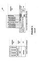
- Figure 5 SDR functional interface diagram.
- Figure 6 is a representation of SDR implementations in wireless handhelds
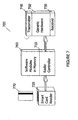
- Figure 7 is a representation of an SDR implementation with a smart card according to disclosed embodiments.
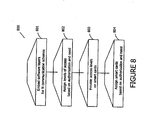
- Figure 8 is a flowchart of implementing a configurable implementation of an SDR according to a disclosed embodiment.
- Figure 9 is a flowchart representing the configuration of an SDR with a smart card according to a disclosed embodiment.
-
- In order to recognize and appreciate the advantages of the disclosed subject matter, an overview of the operation and configuration of Software-Defined Radios follows.
- A
digital radio system 100 consists of three main functional blocks:RF section 110, IFsection 120 andbaseband section 130 as shown in Figure 1. The RF section consists of essentially analog hardware modules while the IF and baseband section typically contain digital hardware modules. TheRF section 110 or front-end is responsible for transmitting/receiving the radio frequency signal from the antenna and converting the RF signal to an intermediate frequency ['IF'') signal. The RF front-end on the receivepath 101 performs RF amplification and analog down conversion from RF to IF. On the transmitpath 102, the RF front-end performs analog up conversion and RF power amplification. - The Analog to Digital Converter ("ADC"), block 121, and the Digital to Analog converter ("DAC"), block 122, perform analog to digital conversion (on the receive path) and digital to analog conversion (on the transmit path), respectively. The ADC and the DAC blocks interface between the analog and digital section of the radio system. The Digital Down Converter ("DDC"), block 123, and the Digital Up Converter ("DUC"), block 124, perform digital down conversion (on the receive path 101) and digital up conversion (on the transmit path 102), respectively. DUC/DDC blocks essentially perform modem operation, i.e., modulation of the signal on the transmit
path 102 and demodulation (digital tuning) of the signal on the receivepath 101. - The
baseband section 130 performs baseband operations (e.g., connection setup, equalization, frequency hopping, timing recovery, correlation) and also implements the link-layer protocol. - The DDC/DUC and baseband processing operations require large amounts of computing power and these modules are generally implemented using Application Specific Integrated Circuits ("ASICs'') or stock Digital Signal Processors ("DSPs"). Implementation of the digital sections using ASICs results in a fixed function digital radio system. If DSPs are used for baseband processing, a Programmable Digital Radio ("PDR") system can be realized. In other words, in a PDR system, baseband operations and link-layer protocols are implemented in software. The DDC/DUC functionality in a PDR system are implemented using ASICs. The limitation of this system is that any change made to the RF section of the system will impact the DDC/DUC operations and will require non-trivial changes to be made in the DDC/DUC ASICs.
- A SDR system is one in which the baseband processing as well as the DDC/DUC modules are programmable. The availability of smart antennas, wideband RF front ends wideband ADC/DAC technologies and ever increasing processing capacity of DSPs and general-purpose microprocessors have fostered the development of multi-band, multi-standard, multi-mode radio systems using SDR technology. In addition, the link-layer protocols and modulation/demodulation operations are implemented in software. The programmability of SDR systems can also be extended to the RF section, e.g., performing analog to digital conversion and vice-versa at the antenna.
- Figure 2 illustrates a software component architecture in a
typical SDR system 200. The system uses ageneric hardware platform 201 with programmable modules (e.g., DSPs, FPGAs, microprocessors) and analog RF modules. The operatingenvironment 202 performs hardware resource management activities such as allocation of hardware resources to different applications, memory management, interrupt servicing and providing a consistent interface to hardware modules for use by applications. In a typical SDR system, the software modules that implement link layer protocols and modulation/demodulation operations may be referred to asradio applications 203 which provide link-layer services to higherlayer communication protocols 204 such as Wireless Application Protocol ("WAP") and Transmission Control Protocol/Internet Protocol ("TCP/IP"). - The capability of general purpose microprocessors can be extended by the addition of math capabilities to create DSPs. Baseband low-speed portions such as vocoding functions are implemented mathematically in DSP Code.
- Traditionally, A/D converters have provided the interface between the analog RF front end and the baseband section. Conventional A/D converters can support SDR implementations. However, A/D converters that are more flexible in dynamic range, bandwidth and other aspects can allow more efficient implementation of SDR.
- Figure 3 illustrates a high-level hierarchical
functional model 300 for a SDR system. Three views of increasing complexity are presented. The top-level view is a simple representation of an entireinformation transfer thread 303. The left side interface is theair interface 301. The right side interface is the wire side and theuser interface 302. The middle-level view identifies a fundamental ordered functional flow of significant and necessary functional areas (front end processing, information security ("infosec"), and information processing and input/output ("I/O'') processing. - The front end processing discussed previously is the functional area of the end user device that consists generically of the physical air interface, the front-end radio frequency processing and any frequency up and down conversion that is necessary. Also, modulation/demodulation processing is contained in this functional block area.
- Information security is employed for the purpose of providing user privacy, authentication, and information protection. In the commercial environment, this protection is specified by the underlying service standard while in the defense environment, this protection is of a nature that must be consistent with the various Governmental doctrines and policies in effect.
- Content or information processing is for the purpose of decomposing or recovering the imbedded information containing data, control, and timing. Content processing and I/0 functions map into path selection (including bridging, routing, and gateway) multiplexing, source coding (including vocoding, and video compression/expansion), signaling protocol, and I/O functions.
- The bottom-level view identifies more detail than the functional middle-level view, such as RF, Modem, Optional Link Processor, comsec, Coding, Internetworking, ETE Security, Signaling Protocol, and I/O.
- The SDR architecture consists of functions connected through open interfaces and procedures for adding software specific tasks to each of the functional areas. The software necessary to operate a SDR is referred to as a software application. Figure 4 shows the SDR open architecture of seven independent subsystems interconnected by open interfaces. The seven subsystems shown are for illustration purposes only and are not intended to be an exhaustive or limiting list. In this view the generalized SDR functional architecture has been particularized by equating a subsystem definition to each functional area. In general, this is not the case. Typically, a subsystem will be determined based on implementation considerations. Interfaces exist for linking software application specific modules into each subsystem. Each subsystem contains hardware, firmware, an operating system, and software modules that may be common to more than one application. The application layer is modular, flexible, and software specific. The common software Application Program Interface ("API") layer, inferred in Figure 4, is standardized with common functions having open and published interfaces.
- Figure 5 represents the functional interface diagram and demonstrates how the SDR architecture extends to the definition of functional interfaces. A representative information flow format is provided at the top of the diagram. Actual representations will be implementation dependent. Interfaces are identified for information and control. For example, information transfer is effected throughout the functional flow within the SDR to/from antenna-RF, RF-modem, Modem-INFOSEC, and INFOSEC-message processing interfaces. Control and status is effected between the same interfaces as information and control is effected between each functional module and one or more control points and interfaces. Auxiliary interfaces are also envisioned.
- SDR provides control over each of the functional blocks as indicated by the control function. As an example, the frequency at which a wireless signal is generated is determined by frequency generation in the RF function. Through the control capability, an SDR terminal would allow this frequency to be changed to accommodate different operating environments.
- The actual user traffic (i.e. data and information) being transmitted follows the paths illustrated by the "I" in Figure 5. SDR works by providing control (the "C" in Figure 5) over each of the functional blocks as indicated by the Control function. As an example, the frequency at which a wireless signal is generated is determined by frequency generation in the RF function. Through the control capability, an SDR terminal would allow this frequency to be changed to accommodate different operating environments (such as moving between regions with different frequency assignments).
- SDR implementations in wireless handhelds can be viewed in comparison with a generic PC model in the form of a multiple service model as illustrated in Figure 6.
- The baseband implementations for each service are shown as cutting through the system software layer and directly interfacing the hardware layer because of the stringent performance constraints on execution speed and power consumption. A variety of technology approaches are being pursued depending on the constraints of the particular application. Battery power, size, with and cost requirements typically push the state of the art in handheld units. In order to achieve processing speed and efficiency, the majority of baseband implementations are programmed very close to the underlying hardware or logic, using low-level languages such as microcode or assembly code. The task of switching between multiple operating bands using the same or different RF hardware is managed by a combination of the service switcher and the controller services for each individual operational mode.
- Figure 7 is an implementation of an embodiment of a SDR according to an aspect of the present disclosure. The Software defined
radio 700 is equipped with asmart card reader 720 that is able to retrieve information contained on thesmart card 770. The smart card may contain information regarding authorization status for security and communication configurations. Aradio controller 710, such as a microprocessor, has access to the various software modules necessary to implement one of many communication schemes including, without limitation, modulation/demodulation type, protocol, and other systems required to enable communications. Theradio 700 includes a memory for storing the multiple software modules. Thememory 760 can be advantageously integrated with the radio controller. Theradio controller 710 selects and runs the appropriate software modules to drive thegeneric hardware 750 which enables thetransmitter 740 to transmit a signal and thereceiver 730 to receive a signal. - Figure 8 is a graphical representation of a method for enabling the dynamic reconfiguration of the SDR with a smartcard. The SDR in
block 801 is embedded with software layers for enabling N communication schemes. Levels of Access may be assigned based on, for example, user authorizations and operational needs inblock 802. The Access levels and operational needs may be encoded on smartcards for distribution to SDR radio operators inblock 803. Of course the distribution of the smartcards may also be determined based on security authorization and operational needs of the individual operator of the organizational unit to which the radio is assigned inblock 804. - Figure 9 is a graphical representation of the operation of the SDR with a smartcard. A user or operator inserts the assigned smartcard into the smartcard reader of the SDR. The smartcard reader retrieves configuration and authorization information from the smart card in
block 901. The SDR, from information contained on the smartcard, determines Access authorization inblock 902 and communication configurations inblock 903. If the authorization is valid, the SDR assigns and executes the appropriate software modules to drive the generic hardware based on the indicated configuration inblock 904. This dynamic configuration is enabled by information from the smart card and thus allows the radio to communicate, for example, with the proper modulation/demodulation, DSP and link protocols as shown inblock 905.
Claims (9)
- A software defined radio comprising:a plurality of communication schemes; a configuration system for selectively enabling one of the plurality of communication schemes comprising a processor, a smartcard reader and a memory; wherein the one of the plurality of communication schemes is selected and enabled by the processor based on information from a user's smartcard.
- The software defined radio according to claim 1, wherein the plurality of communication schemes includes a plurality of communication protocols.
- The software defined radio according to claim 1, wherein the plurality of communication schemes include a plurality of modulation/demodulation techniques.
- The software defined radio according to claim 1, wherein the plurality of communication schemes include a plurality of coding/decoding techniques.
- In a software defined radio ("SDR"), the SDR comprising layered communication information and plural communication protocols, a method of configuring the SDR, the improvement comprising the steps of: providing a smartcard containing configuration information; retrieving the configuration information from the smartcard; and, configuring the SDR based on the configuration information.
- The method of claim 5, comprising the step of selecting the layered communication information and plural communication protocols is based on the configuration information.
- The method of claim 5, wherein the configuration information includes authorization information.
- The method of claim 5, wherein the step of configuring comprises selecting and executing stored software modules for driving generic radio hardware according to the configuration information.
- The method of Claim 5, wherein the specific configuration is selected from the group of AMSSB, FM, PSK, QPSK, QAM, FSK, TDMA, CDMA, FDMA, AMPS, and GSM.
Applications Claiming Priority (2)
| Application Number | Priority Date | Filing Date | Title |
|---|---|---|---|
| US10/661,487 US7406328B2 (en) | 2003-09-15 | 2003-09-15 | System and method for configuring a software radio |
| US661487 | 2003-09-15 |
Publications (2)
| Publication Number | Publication Date |
|---|---|
| EP1515448A1 true EP1515448A1 (en) | 2005-03-16 |
| EP1515448B1 EP1515448B1 (en) | 2016-11-09 |
Family
ID=34136793
Family Applications (1)
| Application Number | Title | Priority Date | Filing Date |
|---|---|---|---|
| EP04021802.6A Expired - Lifetime EP1515448B1 (en) | 2003-09-15 | 2004-09-14 | System and method for configuring a software radio |
Country Status (2)
| Country | Link |
|---|---|
| US (1) | US7406328B2 (en) |
| EP (1) | EP1515448B1 (en) |
Cited By (5)
| Publication number | Priority date | Publication date | Assignee | Title |
|---|---|---|---|---|
| WO2007125459A1 (en) * | 2006-04-28 | 2007-11-08 | Nxp B.V. | Software defined radio device and configuration method of the same |
| WO2009007455A1 (en) * | 2007-07-12 | 2009-01-15 | Icera Inc | Smart card module supporting authentication and software-defined radio function for a wireless device |
| WO2009109687A1 (en) * | 2008-03-06 | 2009-09-11 | Nokia Corporation | A radio frequency apparatus |
| US9020259B2 (en) | 2009-07-20 | 2015-04-28 | Thomson Licensing | Method for detecting and adapting video processing for far-view scenes in sports video |
| EP3719640A1 (en) * | 2019-04-04 | 2020-10-07 | Rohde & Schwarz GmbH & Co. KG | Electronic device and method for operating an electronic device |
Families Citing this family (28)
| Publication number | Priority date | Publication date | Assignee | Title |
|---|---|---|---|---|
| US7885409B2 (en) | 2002-08-28 | 2011-02-08 | Rockwell Collins, Inc. | Software radio system and method |
| EP1505498A1 (en) * | 2003-08-08 | 2005-02-09 | Mitsubishi Electric Information Technology Centre Europe B.V. | Reconfigurable telecommunication device with software components |
| KR100548414B1 (en) * | 2003-10-09 | 2006-02-02 | 엘지전자 주식회사 | Mobile communication terminal with triple mode |
| KR100585741B1 (en) * | 2003-10-20 | 2006-06-07 | 엘지전자 주식회사 | Multimedia handheld terminal |
| US7193435B2 (en) * | 2005-02-04 | 2007-03-20 | Itt Manufacturing Enterprises, Inc. | Programmable application specific integrated circuit for communication and other applications |
| US7769912B2 (en) * | 2005-02-17 | 2010-08-03 | Samsung Electronics Co., Ltd. | Multistandard SDR architecture using context-based operation reconfigurable instruction set processors |
| US8463319B2 (en) * | 2005-06-17 | 2013-06-11 | Honeywell International Inc. | Wireless application installation, configuration and management tool |
| US7681239B2 (en) * | 2005-09-30 | 2010-03-16 | Microsoft Corporation | Modularly constructing a software defined radio |
| US7784029B2 (en) * | 2005-09-30 | 2010-08-24 | Microsoft Corporation | Network service for modularly constructing a software defined radio |
| US8396041B2 (en) | 2005-11-08 | 2013-03-12 | Microsoft Corporation | Adapting a communication network to varying conditions |
| US8381047B2 (en) | 2005-11-30 | 2013-02-19 | Microsoft Corporation | Predicting degradation of a communication channel below a threshold based on data transmission errors |
| US8606259B2 (en) * | 2006-06-28 | 2013-12-10 | Samsung Electronics Co., Ltd. | Method and system for testing a software-defined radio device |
| US7720506B1 (en) | 2006-07-28 | 2010-05-18 | Rockwell Collins, Inc. | System and method of providing antenna specific front ends for aviation software defined radios |
| US7831255B1 (en) * | 2006-07-31 | 2010-11-09 | Rockwell Collins, Inc. | System and method of providing automated availability and integrity verification for aviation software defined radios |
| US7847730B2 (en) * | 2006-09-27 | 2010-12-07 | Bae Systems Information And Electronic Systems Integration, Inc. | Software defined navigation signal generator |
| WO2008099425A2 (en) * | 2007-02-16 | 2008-08-21 | Sloka Telecom Pvt.Ltd. | Software defined base station |
| US8054779B2 (en) * | 2007-05-08 | 2011-11-08 | Microsoft Corporation | Simultaneous wireless support in software defined radio |
| US8340714B2 (en) | 2007-12-14 | 2012-12-25 | Microsoft Corporation | Computing device with configurable antenna |
| CA2733895A1 (en) | 2008-08-11 | 2010-02-18 | Marport Canada Inc. | Multi-function broadband phased-array software defined sonar system and method |
| US20110105094A1 (en) * | 2009-10-29 | 2011-05-05 | Microsoft Corporation | Location integration in software defined radio |
| US8666311B2 (en) * | 2010-08-02 | 2014-03-04 | Cisco Technology, Inc. | Satellite on-board RFI detection |
| ES2746900T3 (en) * | 2010-10-06 | 2020-03-09 | Univ Hanyang Ind Univ Coop Found | Smart antenna software definition radio terminal device and procedure for distributing and installing a software definition radio terminal application |
| EP2838014B1 (en) * | 2012-04-12 | 2019-05-15 | Industry-University Cooperation Foundation Hanyang University | Method for distributing, installing and executing software-defined radio application |
| US9307409B2 (en) | 2013-12-27 | 2016-04-05 | Intel Corporation | Apparatus, system and method of protecting domains of a multimode wireless radio transceiver |
| US9614551B2 (en) * | 2014-02-24 | 2017-04-04 | Intel IP Corporation | Device, system and method of configuring a radio transceiver |
| US10256847B2 (en) * | 2014-08-20 | 2019-04-09 | Neo Sastech Co., Ltd. | Method and terminal device for executing radio application |
| EP3639530B1 (en) | 2017-06-15 | 2022-03-02 | Telefonaktiebolaget LM Ericsson (PUBL) | Hardware platform based on fpga partial reconfiguration for wireless communication device |
| CN110649992B (en) * | 2019-10-22 | 2022-03-25 | 大唐终端技术有限公司 | Self-organizing network service channel self-adaptive modulation method based on SDR |
Family Cites Families (14)
| Publication number | Priority date | Publication date | Assignee | Title |
|---|---|---|---|---|
| US5999811A (en) * | 1996-02-16 | 1999-12-07 | Ericsson, Inc. | Mobile telephone for roaming using dual mode/band equipment including SIM cards |
| DE19734933C1 (en) * | 1997-08-12 | 1999-02-18 | Siemens Ag | Method, mobile station and communication system for adapting to an air interface access method supported by a mobile radio network |
| US6504867B1 (en) | 1998-03-26 | 2003-01-07 | Analog Devices, Inc. | Digital matched filtering for signal estimation in a digital receiver |
| US6125283A (en) * | 1998-05-18 | 2000-09-26 | Ericsson Inc. | Multi-mode mobile terminal and methods for operating the same |
| US6353846B1 (en) | 1998-11-02 | 2002-03-05 | Harris Corporation | Property based resource manager system |
| US6577229B1 (en) * | 1999-06-10 | 2003-06-10 | Cubic Corporation | Multiple protocol smart card communication device |
| US6526110B1 (en) | 1999-09-14 | 2003-02-25 | Mitsubishi Electric Research Laboratories Inc. | Embedded RAM based digital signal processor |
| FI115355B (en) * | 2000-06-22 | 2005-04-15 | Icl Invia Oyj | Arrangements for identification and verification of a user in a protected system |
| US6785556B2 (en) * | 2000-08-11 | 2004-08-31 | Novatel Wireless, Inc. | Method and apparatus for a software configurable wireless modem adaptable for multiple modes of operation |
| US7151925B2 (en) * | 2001-09-10 | 2006-12-19 | Industrial Technology Research Institute | Software defined radio (SDR) architecture for wireless digital communication systems |
| GB2386504B (en) * | 2002-03-12 | 2005-03-02 | Toshiba Res Europ Ltd | Alternative radio system monitoring |
| US6959349B2 (en) * | 2002-05-17 | 2005-10-25 | Abocom Systems, Inc. | Wireless computer peripheral interface with the capability of identification |
| US20040005914A1 (en) * | 2002-07-08 | 2004-01-08 | Dear Jean Paul | Wireless communicator with integral display |
| US7369982B2 (en) * | 2003-06-04 | 2008-05-06 | Stmicroelectronics, Inc. | Multi-mode smart card emulator and related methods |
-
2003
- 2003-09-15 US US10/661,487 patent/US7406328B2/en not_active Expired - Lifetime
-
2004
- 2004-09-14 EP EP04021802.6A patent/EP1515448B1/en not_active Expired - Lifetime
Non-Patent Citations (1)
| Title |
|---|
| C. PREHOFER, Q.WEI: "Active Networks for 4G Mobile Communication: Motivation, Architecture and Application Scenarios", PROC. OF IWAN 02, LNCS 2546, 2002, SPRINGER, XP002308070 * |
Cited By (11)
| Publication number | Priority date | Publication date | Assignee | Title |
|---|---|---|---|---|
| WO2007125459A1 (en) * | 2006-04-28 | 2007-11-08 | Nxp B.V. | Software defined radio device and configuration method of the same |
| US9088341B2 (en) | 2006-04-28 | 2015-07-21 | Telefonaktiebolaget L M Ericsson (Publ) | Software defined radio device and configuration method of the same |
| WO2009007455A1 (en) * | 2007-07-12 | 2009-01-15 | Icera Inc | Smart card module supporting authentication and software-defined radio function for a wireless device |
| GB2463585A (en) * | 2007-07-12 | 2010-03-24 | Icera Inc | Smart card module supporting authentication and software-defined radio function for a wireless device |
| GB2463585B (en) * | 2007-07-12 | 2012-07-18 | Icera Inc | Smart card module supporting authentication and software-defined radio function for a wireless device |
| US8285324B2 (en) | 2007-07-12 | 2012-10-09 | Icera Inc. | Smart card module supporting authentication and software-defined radio function for a wireless device |
| WO2009109687A1 (en) * | 2008-03-06 | 2009-09-11 | Nokia Corporation | A radio frequency apparatus |
| CN101965749B (en) * | 2008-03-06 | 2013-05-15 | 诺基亚公司 | Radio frequency apparatus |
| US9178537B2 (en) | 2008-03-06 | 2015-11-03 | Nokia Technologies Oy | Radio frequency apparatus |
| US9020259B2 (en) | 2009-07-20 | 2015-04-28 | Thomson Licensing | Method for detecting and adapting video processing for far-view scenes in sports video |
| EP3719640A1 (en) * | 2019-04-04 | 2020-10-07 | Rohde & Schwarz GmbH & Co. KG | Electronic device and method for operating an electronic device |
Also Published As
| Publication number | Publication date |
|---|---|
| US7406328B2 (en) | 2008-07-29 |
| US20050059427A1 (en) | 2005-03-17 |
| EP1515448B1 (en) | 2016-11-09 |
Similar Documents
| Publication | Publication Date | Title |
|---|---|---|
| US7406328B2 (en) | System and method for configuring a software radio | |
| CN107819675B (en) | Internet of things gateway and Internet of things communication method | |
| US7188159B2 (en) | Efficient software download to configurable communication device | |
| Mitola | Technical challenges in the globalization of software radio | |
| CN100534026C (en) | Bluetooth RF Based RF Tag Read/Write Station | |
| US20090207025A1 (en) | Transmitter and receiver for combining rfid amplitude-modulated data with wireless phase-modulated data | |
| US20100220686A1 (en) | Method and apparatus for cognitive radio policy change | |
| WO2004045240A1 (en) | Secure network-routed voice multicast dissemination | |
| US20090033494A1 (en) | Vehicular mobile rf tags | |
| CN115485977B (en) | Signal transmission method, device, storage medium and chip system | |
| CN105607081A (en) | Air-traffic control emergency rescue Beidou communication and navigation integrated system | |
| US20090036104A1 (en) | Mobile rf tags locatable using cell phone | |
| US20150245354A1 (en) | Method and device for sending/receiving electromagnetic signals received/sent on one or more first frequency bands | |
| CN205539477U (en) | Big dipper communication navigation integration airborne terminal | |
| Ashley | Cognitive radio | |
| Patzold | Countdown for the full-scale development of 5G new radio [mobile radio] | |
| JP2006229778A (en) | Radio frequency assignment apparatus, radio communication system, and radio frequency assignment method | |
| CN113938153B (en) | Communication equipment and data transmission method and device | |
| US20080084922A1 (en) | Multiprotocol multiplex wireless communication apparatus and methods | |
| Aziz et al. | Enabling 5G and DSRC V2X in Autonomous Driving Vehicles | |
| CN120077595A (en) | Method and apparatus for wireless communication | |
| EP1213887A1 (en) | Radio communication apparatus and radio communication method | |
| Caicedo et al. | Software defined radio and software radio technology: Concepts and applications | |
| Yáñez-Casas et al. | High data rate efficiency improvement via variable length coding for LoRaWAN | |
| Fox | Software defined radios-Motorola's wireless information transfer system (WITS) |
Legal Events
| Date | Code | Title | Description |
|---|---|---|---|
| PUAI | Public reference made under article 153(3) epc to a published international application that has entered the european phase |
Free format text: ORIGINAL CODE: 0009012 |
|
| 17P | Request for examination filed |
Effective date: 20040914 |
|
| AK | Designated contracting states |
Kind code of ref document: A1 Designated state(s): AT BE BG CH CY CZ DE DK EE ES FI FR GB GR HU IE IT LI LU MC NL PL PT RO SE SI SK TR |
|
| AX | Request for extension of the european patent |
Extension state: AL HR LT LV MK |
|
| AKX | Designation fees paid |
Designated state(s): AT BE BG CH CY CZ DE DK EE ES FI FR GB GR HU IE IT LI LU MC NL PL PT RO SE SI SK TR |
|
| GRAP | Despatch of communication of intention to grant a patent |
Free format text: ORIGINAL CODE: EPIDOSNIGR1 |
|
| INTG | Intention to grant announced |
Effective date: 20160520 |
|
| GRAS | Grant fee paid |
Free format text: ORIGINAL CODE: EPIDOSNIGR3 |
|
| GRAA | (expected) grant |
Free format text: ORIGINAL CODE: 0009210 |
|
| RAP1 | Party data changed (applicant data changed or rights of an application transferred) |
Owner name: HARRIS CORPORATION |
|
| AK | Designated contracting states |
Kind code of ref document: B1 Designated state(s): AT BE BG CH CY CZ DE DK EE ES FI FR GB GR HU IE IT LI LU MC NL PL PT RO SE SI SK TR |
|
| REG | Reference to a national code |
Ref country code: GB Ref legal event code: FG4D |
|
| REG | Reference to a national code |
Ref country code: DE Ref legal event code: R081 Ref document number: 602004050242 Country of ref document: DE Owner name: HARRIS GLOBAL COMMUNICATIONS, INC., ALBANY, US Free format text: FORMER OWNER: HARRIS CORP., MELBOURNE, FLA., US |
|
| REG | Reference to a national code |
Ref country code: AT Ref legal event code: REF Ref document number: 844756 Country of ref document: AT Kind code of ref document: T Effective date: 20161115 Ref country code: CH Ref legal event code: EP |
|
| REG | Reference to a national code |
Ref country code: IE Ref legal event code: FG4D |
|
| REG | Reference to a national code |
Ref country code: DE Ref legal event code: R096 Ref document number: 602004050242 Country of ref document: DE |
|
| REG | Reference to a national code |
Ref country code: NL Ref legal event code: MP Effective date: 20161109 |
|
| REG | Reference to a national code |
Ref country code: AT Ref legal event code: MK05 Ref document number: 844756 Country of ref document: AT Kind code of ref document: T Effective date: 20161109 |
|
| PG25 | Lapsed in a contracting state [announced via postgrant information from national office to epo] |
Ref country code: NL Free format text: LAPSE BECAUSE OF FAILURE TO SUBMIT A TRANSLATION OF THE DESCRIPTION OR TO PAY THE FEE WITHIN THE PRESCRIBED TIME-LIMIT Effective date: 20161109 Ref country code: GR Free format text: LAPSE BECAUSE OF FAILURE TO SUBMIT A TRANSLATION OF THE DESCRIPTION OR TO PAY THE FEE WITHIN THE PRESCRIBED TIME-LIMIT Effective date: 20170210 Ref country code: SE Free format text: LAPSE BECAUSE OF FAILURE TO SUBMIT A TRANSLATION OF THE DESCRIPTION OR TO PAY THE FEE WITHIN THE PRESCRIBED TIME-LIMIT Effective date: 20161109 |
|
| PG25 | Lapsed in a contracting state [announced via postgrant information from national office to epo] |
Ref country code: AT Free format text: LAPSE BECAUSE OF FAILURE TO SUBMIT A TRANSLATION OF THE DESCRIPTION OR TO PAY THE FEE WITHIN THE PRESCRIBED TIME-LIMIT Effective date: 20161109 Ref country code: FI Free format text: LAPSE BECAUSE OF FAILURE TO SUBMIT A TRANSLATION OF THE DESCRIPTION OR TO PAY THE FEE WITHIN THE PRESCRIBED TIME-LIMIT Effective date: 20161109 Ref country code: ES Free format text: LAPSE BECAUSE OF FAILURE TO SUBMIT A TRANSLATION OF THE DESCRIPTION OR TO PAY THE FEE WITHIN THE PRESCRIBED TIME-LIMIT Effective date: 20161109 Ref country code: PT Free format text: LAPSE BECAUSE OF FAILURE TO SUBMIT A TRANSLATION OF THE DESCRIPTION OR TO PAY THE FEE WITHIN THE PRESCRIBED TIME-LIMIT Effective date: 20170309 Ref country code: PL Free format text: LAPSE BECAUSE OF FAILURE TO SUBMIT A TRANSLATION OF THE DESCRIPTION OR TO PAY THE FEE WITHIN THE PRESCRIBED TIME-LIMIT Effective date: 20161109 |
|
| PG25 | Lapsed in a contracting state [announced via postgrant information from national office to epo] |
Ref country code: EE Free format text: LAPSE BECAUSE OF FAILURE TO SUBMIT A TRANSLATION OF THE DESCRIPTION OR TO PAY THE FEE WITHIN THE PRESCRIBED TIME-LIMIT Effective date: 20161109 Ref country code: RO Free format text: LAPSE BECAUSE OF FAILURE TO SUBMIT A TRANSLATION OF THE DESCRIPTION OR TO PAY THE FEE WITHIN THE PRESCRIBED TIME-LIMIT Effective date: 20161109 Ref country code: DK Free format text: LAPSE BECAUSE OF FAILURE TO SUBMIT A TRANSLATION OF THE DESCRIPTION OR TO PAY THE FEE WITHIN THE PRESCRIBED TIME-LIMIT Effective date: 20161109 Ref country code: CZ Free format text: LAPSE BECAUSE OF FAILURE TO SUBMIT A TRANSLATION OF THE DESCRIPTION OR TO PAY THE FEE WITHIN THE PRESCRIBED TIME-LIMIT Effective date: 20161109 Ref country code: SK Free format text: LAPSE BECAUSE OF FAILURE TO SUBMIT A TRANSLATION OF THE DESCRIPTION OR TO PAY THE FEE WITHIN THE PRESCRIBED TIME-LIMIT Effective date: 20161109 |
|
| REG | Reference to a national code |
Ref country code: DE Ref legal event code: R097 Ref document number: 602004050242 Country of ref document: DE |
|
| PG25 | Lapsed in a contracting state [announced via postgrant information from national office to epo] |
Ref country code: BG Free format text: LAPSE BECAUSE OF FAILURE TO SUBMIT A TRANSLATION OF THE DESCRIPTION OR TO PAY THE FEE WITHIN THE PRESCRIBED TIME-LIMIT Effective date: 20170209 Ref country code: BE Free format text: LAPSE BECAUSE OF FAILURE TO SUBMIT A TRANSLATION OF THE DESCRIPTION OR TO PAY THE FEE WITHIN THE PRESCRIBED TIME-LIMIT Effective date: 20161109 |
|
| PLBE | No opposition filed within time limit |
Free format text: ORIGINAL CODE: 0009261 |
|
| STAA | Information on the status of an ep patent application or granted ep patent |
Free format text: STATUS: NO OPPOSITION FILED WITHIN TIME LIMIT |
|
| REG | Reference to a national code |
Ref country code: FR Ref legal event code: PLFP Year of fee payment: 14 |
|
| 26N | No opposition filed |
Effective date: 20170810 |
|
| PG25 | Lapsed in a contracting state [announced via postgrant information from national office to epo] |
Ref country code: SI Free format text: LAPSE BECAUSE OF FAILURE TO SUBMIT A TRANSLATION OF THE DESCRIPTION OR TO PAY THE FEE WITHIN THE PRESCRIBED TIME-LIMIT Effective date: 20161109 |
|
| REG | Reference to a national code |
Ref country code: CH Ref legal event code: PL |
|
| PG25 | Lapsed in a contracting state [announced via postgrant information from national office to epo] |
Ref country code: MC Free format text: LAPSE BECAUSE OF FAILURE TO SUBMIT A TRANSLATION OF THE DESCRIPTION OR TO PAY THE FEE WITHIN THE PRESCRIBED TIME-LIMIT Effective date: 20161109 |
|
| REG | Reference to a national code |
Ref country code: IE Ref legal event code: MM4A |
|
| PG25 | Lapsed in a contracting state [announced via postgrant information from national office to epo] |
Ref country code: LU Free format text: LAPSE BECAUSE OF NON-PAYMENT OF DUE FEES Effective date: 20170914 |
|
| PG25 | Lapsed in a contracting state [announced via postgrant information from national office to epo] |
Ref country code: LI Free format text: LAPSE BECAUSE OF NON-PAYMENT OF DUE FEES Effective date: 20170930 Ref country code: CH Free format text: LAPSE BECAUSE OF NON-PAYMENT OF DUE FEES Effective date: 20170930 Ref country code: IE Free format text: LAPSE BECAUSE OF NON-PAYMENT OF DUE FEES Effective date: 20170914 |
|
| REG | Reference to a national code |
Ref country code: FR Ref legal event code: PLFP Year of fee payment: 15 |
|
| REG | Reference to a national code |
Ref country code: DE Ref legal event code: R082 Ref document number: 602004050242 Country of ref document: DE Representative=s name: WUESTHOFF & WUESTHOFF, PATENTANWAELTE PARTG MB, DE Ref country code: DE Ref legal event code: R081 Ref document number: 602004050242 Country of ref document: DE Owner name: HARRIS GLOBAL COMMUNICATIONS, INC., ALBANY, US Free format text: FORMER OWNER: HARRIS CORPORATION, MELBOURNE, FLA., US Ref country code: DE Ref legal event code: R081 Ref document number: 602004050242 Country of ref document: DE Owner name: HARRIS GLOBAL COMMUNICATIONS, INC., ALBANY, US Free format text: FORMER OWNER: HARRIS CORPORATION, MELBOURNE, FL, US |
|
| REG | Reference to a national code |
Ref country code: GB Ref legal event code: 732E Free format text: REGISTERED BETWEEN 20190207 AND 20190213 |
|
| PG25 | Lapsed in a contracting state [announced via postgrant information from national office to epo] |
Ref country code: HU Free format text: LAPSE BECAUSE OF FAILURE TO SUBMIT A TRANSLATION OF THE DESCRIPTION OR TO PAY THE FEE WITHIN THE PRESCRIBED TIME-LIMIT; INVALID AB INITIO Effective date: 20040914 |
|
| PG25 | Lapsed in a contracting state [announced via postgrant information from national office to epo] |
Ref country code: CY Free format text: LAPSE BECAUSE OF NON-PAYMENT OF DUE FEES Effective date: 20161109 |
|
| PG25 | Lapsed in a contracting state [announced via postgrant information from national office to epo] |
Ref country code: TR Free format text: LAPSE BECAUSE OF FAILURE TO SUBMIT A TRANSLATION OF THE DESCRIPTION OR TO PAY THE FEE WITHIN THE PRESCRIBED TIME-LIMIT Effective date: 20161109 |
|
| PGFP | Annual fee paid to national office [announced via postgrant information from national office to epo] |
Ref country code: GB Payment date: 20220927 Year of fee payment: 19 Ref country code: DE Payment date: 20220928 Year of fee payment: 19 |
|
| PGFP | Annual fee paid to national office [announced via postgrant information from national office to epo] |
Ref country code: FR Payment date: 20220926 Year of fee payment: 19 |
|
| PGFP | Annual fee paid to national office [announced via postgrant information from national office to epo] |
Ref country code: IT Payment date: 20220926 Year of fee payment: 19 |
|
| P01 | Opt-out of the competence of the unified patent court (upc) registered |
Effective date: 20230530 |
|
| REG | Reference to a national code |
Ref country code: DE Ref legal event code: R119 Ref document number: 602004050242 Country of ref document: DE |
|
| GBPC | Gb: european patent ceased through non-payment of renewal fee |
Effective date: 20230914 |
|
| PG25 | Lapsed in a contracting state [announced via postgrant information from national office to epo] |
Ref country code: GB Free format text: LAPSE BECAUSE OF NON-PAYMENT OF DUE FEES Effective date: 20230914 |
|
| PG25 | Lapsed in a contracting state [announced via postgrant information from national office to epo] |
Ref country code: GB Free format text: LAPSE BECAUSE OF NON-PAYMENT OF DUE FEES Effective date: 20230914 Ref country code: FR Free format text: LAPSE BECAUSE OF NON-PAYMENT OF DUE FEES Effective date: 20230930 Ref country code: DE Free format text: LAPSE BECAUSE OF NON-PAYMENT OF DUE FEES Effective date: 20240403 |
|
| PG25 | Lapsed in a contracting state [announced via postgrant information from national office to epo] |
Ref country code: IT Free format text: LAPSE BECAUSE OF NON-PAYMENT OF DUE FEES Effective date: 20230914 |
|
| PG25 | Lapsed in a contracting state [announced via postgrant information from national office to epo] |
Ref country code: IT Free format text: LAPSE BECAUSE OF NON-PAYMENT OF DUE FEES Effective date: 20230914 |