EP1515377A1 - Method of operating an injector comprising a piezoelectric actuator - Google Patents
Method of operating an injector comprising a piezoelectric actuator Download PDFInfo
- Publication number
- EP1515377A1 EP1515377A1 EP03103328A EP03103328A EP1515377A1 EP 1515377 A1 EP1515377 A1 EP 1515377A1 EP 03103328 A EP03103328 A EP 03103328A EP 03103328 A EP03103328 A EP 03103328A EP 1515377 A1 EP1515377 A1 EP 1515377A1
- Authority
- EP
- European Patent Office
- Prior art keywords
- voltage
- injector
- piezoelectric
- fuel injector
- actuator
- Prior art date
- Legal status (The legal status is an assumption and is not a legal conclusion. Google has not performed a legal analysis and makes no representation as to the accuracy of the status listed.)
- Granted
Links
- 238000000034 method Methods 0.000 title claims abstract description 18
- 238000006073 displacement reaction Methods 0.000 claims abstract description 35
- 239000000446 fuel Substances 0.000 claims abstract description 28
- 238000011084 recovery Methods 0.000 claims abstract description 21
- 238000002485 combustion reaction Methods 0.000 claims description 20
- 239000002283 diesel fuel Substances 0.000 claims description 4
- 238000002347 injection Methods 0.000 description 7
- 239000007924 injection Substances 0.000 description 7
- 239000012530 fluid Substances 0.000 description 5
- 239000000463 material Substances 0.000 description 5
- 230000032683 aging Effects 0.000 description 4
- 230000000694 effects Effects 0.000 description 3
- 238000010586 diagram Methods 0.000 description 2
- 230000003716 rejuvenation Effects 0.000 description 2
- 230000003679 aging effect Effects 0.000 description 1
- 229910010293 ceramic material Inorganic materials 0.000 description 1
- 230000009849 deactivation Effects 0.000 description 1
- 230000001419 dependent effect Effects 0.000 description 1
- 230000005684 electric field Effects 0.000 description 1
- 230000001747 exhibiting effect Effects 0.000 description 1
- 238000004519 manufacturing process Methods 0.000 description 1
- 238000004806 packaging method and process Methods 0.000 description 1
Images

Classifications
-
- F—MECHANICAL ENGINEERING; LIGHTING; HEATING; WEAPONS; BLASTING
- F02—COMBUSTION ENGINES; HOT-GAS OR COMBUSTION-PRODUCT ENGINE PLANTS
- F02D—CONTROLLING COMBUSTION ENGINES
- F02D41/00—Electrical control of supply of combustible mixture or its constituents
- F02D41/20—Output circuits, e.g. for controlling currents in command coils
- F02D41/2096—Output circuits, e.g. for controlling currents in command coils for controlling piezoelectric injectors
-
- F—MECHANICAL ENGINEERING; LIGHTING; HEATING; WEAPONS; BLASTING
- F02—COMBUSTION ENGINES; HOT-GAS OR COMBUSTION-PRODUCT ENGINE PLANTS
- F02D—CONTROLLING COMBUSTION ENGINES
- F02D41/00—Electrical control of supply of combustible mixture or its constituents
- F02D41/20—Output circuits, e.g. for controlling currents in command coils
- F02D2041/202—Output circuits, e.g. for controlling currents in command coils characterised by the control of the circuit
- F02D2041/2051—Output circuits, e.g. for controlling currents in command coils characterised by the control of the circuit using voltage control
-
- F—MECHANICAL ENGINEERING; LIGHTING; HEATING; WEAPONS; BLASTING
- F02—COMBUSTION ENGINES; HOT-GAS OR COMBUSTION-PRODUCT ENGINE PLANTS
- F02D—CONTROLLING COMBUSTION ENGINES
- F02D41/00—Electrical control of supply of combustible mixture or its constituents
- F02D41/008—Controlling each cylinder individually
- F02D41/0087—Selective cylinder activation, i.e. partial cylinder operation
-
- F—MECHANICAL ENGINEERING; LIGHTING; HEATING; WEAPONS; BLASTING
- F02—COMBUSTION ENGINES; HOT-GAS OR COMBUSTION-PRODUCT ENGINE PLANTS
- F02D—CONTROLLING COMBUSTION ENGINES
- F02D41/00—Electrical control of supply of combustible mixture or its constituents
- F02D41/02—Circuit arrangements for generating control signals
- F02D41/04—Introducing corrections for particular operating conditions
- F02D41/042—Introducing corrections for particular operating conditions for stopping the engine
Definitions
- the present invention generally relates to fuel injectors actuated with a piezoelectric actuator or piezoelectric stack.
- US patent 6,464,149 describes an actuator arrangement comprising a piezoelectric element formed from a piezoelectric material, a first end of the piezoelectric element cooperating with an input piston member slidable within a bore surface associated with the input piston member defining, in part, a control chamber for fluid pressure within the control chamber acting on a surface associated with an output piston member, the fluid within the control chamber being substantially incompressible such that, in use, movement of the input piston member is transmitted to the output piston member, the piezoelectric element being arranged within a chamber for fluid such that fluid pressure within the chamber exerts a force on at least a part of the surface of the piezoelectric element which serves to oppose a load exerted on the piezoelectric element due to fluid pressure within the control chamber, thereby suppressing distortions in the piezoelectric material.
- US patent 5,779,149 shows a fuel injector for an internal combustion engine using a hydraulic amplifier to increase the stroke of a piezoelectric actuator for opening a normally closed drain valve associated with a hydraulic control chamber.
- EP 1 209 351 A1 discloses a fuel injector for an internal combustion engine comprising a housing with an actuator chamber, a piezoelectric actuator arranged in the actuator chamber, an injector control valve and a hydraulic stroke amplifier module.
- the hydraulic stroke amplifier module is located axially in-between the injector control valve and the piezoelectric actuator.
- the activity of the piezoelectric actuator and in particular of the piezoelectric material used in the actuator, can be defined as the relationship between the voltage applied to the actuator and the displacement of the actuator ends.
- a technical problem underlying the present invention is to provide a method, which minimizes the loss of displacement/stroke in a piezoelectric multi layer actuator.
- the object of the present invention is to provide an improved driving method for operating a fuel injector comprising a piezoelectric actuator that minimizes or even overcomes the above-cited ageing effect.
- a method of operating an injector comprising a piezoelectric actuator for displacing an injector needle to open an injector port is proposed.
- a voltage within a voltage operating range is applied to the piezoelectric actuator to cause the displacement of the needle.
- the voltage operating range can be bipolar i.e. positive or negative voltage.
- the piezoelectric stack of the piezoelectric actuator is able to receive several voltage values within the operating range. The maximum voltage value within the operating range is determined by the driving circuit possibility and by the piezoelectric stack itself.
- a recovery voltage equal or superior to the reverse coercive field voltage value corresponding to the piezoelectric material used in the actuator is applied to the piezoelectric stack.
- the coercive field voltage value is the voltage value where the ceramic material of the piezoelectric stack starts to depolarise. When depolarisation occurs, a majority of the dipoles are switching back to their original, random orientation i.e. not in alignment with the electrical field. Thus, the expansion of the piezoelectric stack is back to almost its original value, just as if it had never been operated.
- the coercive field voltage value designated with the word "reverse" has the opposite sign of the voltage range where the piezoelectric actuator is operated.
- the recovery voltage is applied when the fuel injector is not injecting fuel. The present method is used at a moment in the fuel injector usage cycle when no fuel injection is needed. This allows time for the recovery effect to take place.
- the fuel injector is mounted on an internal combustion engine and the recovery voltage is applied after the internal combustion engine has been shut off. Once the engine has been shut off, there is time to perform the recovery procedure. Consequently, all the injectors of an internal combustion engine are prepared for optimum behaviour at the next engine start.
- a multi-cylinder internal combustion engine which has a plurality of combustion chambers, can be operated with one combustion chamber producing no pressure raise.
- This operation commonly known in the automotive industry as cylinder deactivation, allows running an internal combustion engine on fewer cylinders than it actually has. The engine is still producing power and allows in the same time to operate the non-energised cylinder in a different way.
- the recovery voltage can thus be applied to the fuel injector of the deactivated cylinder.
- This kind of strategy may also be applied if the actuator has reached its ageing limit and if the engine has not been shut off recently.
- Each cylinder may be deactivated in turn so as to "reset" the piezoelectric actuators of each fuel injector at predetermined intervals. This situation can also occur with internal combustion engines used for continuous duty applications, for example in energy production.
- the fuel injector is a Diesel fuel injector.
- the piezoelectric actuator can be used in other types of fuel injectors, the Diesel fuel injector is particularly suited for application of such piezoelectric actuators. Diesel fuel injectors need fast actuators to allow them the highest driving flexibility because improved injection timing strategies foresee a considerable number of injection events during one engine stroke.
- the internal combustion engine is mounted in an automotive vehicle.
- the automotive industry is the biggest consumer of internal combustion engines.
- the market share of cars equipped with Diesel engine is increasing, as these engines are more value added for the final consumer as their gasoline counterparts.
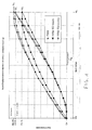
- FIG. 1 shows three curves of a piezoelectric stack displacement versus an applied voltage.
- a first look at the curve called "New" (triangle-dotted line) reveals that when the applied voltage is raised from V1 to V2, the piezoelectric stack does not expand in the same manner as when the voltage is reduced from V2 to V1.
- the piezoelectric stack thus shows a hysteresis type of behaviour.
- both parts of the curve called “New” show a change in their inflexion.
- V3 is a range where a change in the physical behaviour of the piezoelectric stack occurs.
- the curve called “After 60 hours” shows the response of the same piezoelectric stack after about 60 hours of operation, e.g. about several million cycles of expansion and retraction in a highly pressurised environment.
- the stack displacement is about 12.5% less after 60 hours of operation (see Fig. 1 - D3 compared to D2 on the curve called "after 60 hours”).
- a major drawback of the ageing of the piezoelectric stack is cost related because the piezoelectric stack needs to be aged before being used in an injector.
- This operation can be incorporated in the fuel system management device and done when the injector is not operating.
- the recovery operation has to be done on a regular basis.
- An electronic fuel management system device can easily provide a function that would count the total operating time or the total amount of injections an injector has done since its last recovery operation. Thus the time period when to perform another recovery operation can be determined easily.
- the piezoelectric stack displacement versus applied voltage of the same aged piezoelectric stack was measured again after a recovery procedure was performed.
- the curve called "After recovery” shows the stack displacement after the recovery procedure.
- the maximum displacement of the piezoelectric stack D4 has gained about 15% as compared to the stack displacement before recovery (D3) and is again comparable to the stack displacement of a new piezoelectric stack (D2).
- the curve called "After recovery” is indeed very close to the original curve called "New", showing that after the recovery procedure, the piezoelectric stack has again displacements which are very similar to those it had when it was new.
- Fig. 2 shows a piezoelectric stack displacement versus an applied voltage where the voltage applied is either positive (right side of Fig. 2) or negative (left side of Fig. 2).
- the curve called "Direct Operating Loop” (diamond-dotted line) is the equivalent of the curve called “New” of Fig. 1. It shows the piezoelectric stack displacement versus the applied voltage.
- the hysteresis curve called "Direct Operating Loop” closes at V10 and D10 and at V20 and D20.
- the curve called "Reverse Operating Loop” (square-dotted line) is more or less a vertical mirrored view of the curve called “Direct Operating Loop”. It shows that when a negative voltage is applied to the piezoelectric stack, the latter has substantially the same behaviour as with a corresponding positive voltage with regard to its displacement. This time closing points reach from V30 and D20 to V40 and D10.
- the curve called "Reverse Operating Loop” has also a coercive field voltage value. This value corresponds substantially to the opposite of the coercive field voltage value (Vc) of curve called “Direct Operating Loop” and is called reverse coercive field voltage (Vrc).
- the diagram formed hereby is typical for a piezoelectric stack and is called "Butterfly Curve".
- Positive displacement of the piezoelectric stack e.g. expansion is achieved by applying a positive or a negative voltage to the piezoelectric stack.
- a positive or a negative voltage to the piezoelectric stack.
- the expansion of the piezoelectric stack is used in a fuel injector to control its opening and closing. The longer an injector is opened, the longer it will inject fuel.
Landscapes
- Engineering & Computer Science (AREA)
- Chemical & Material Sciences (AREA)
- Combustion & Propulsion (AREA)
- Mechanical Engineering (AREA)
- General Engineering & Computer Science (AREA)
- Fuel-Injection Apparatus (AREA)
- Electrical Control Of Air Or Fuel Supplied To Internal-Combustion Engine (AREA)
Abstract
Description
- The present invention generally relates to fuel injectors actuated with a piezoelectric actuator or piezoelectric stack.
- In the automotive industry, the state of the art for fast actuating fuel injectors uses piezoelectric actuators as, for example, nowadays Diesel engines have up to five short injection events during one stroke. Beside the main injection event, the other events are mostly for noise and emission levels reduction purposes.
- US patent 6,464,149 describes an actuator arrangement comprising a piezoelectric element formed from a piezoelectric material, a first end of the piezoelectric element cooperating with an input piston member slidable within a bore surface associated with the input piston member defining, in part, a control chamber for fluid pressure within the control chamber acting on a surface associated with an output piston member, the fluid within the control chamber being substantially incompressible such that, in use, movement of the input piston member is transmitted to the output piston member, the piezoelectric element being arranged within a chamber for fluid such that fluid pressure within the chamber exerts a force on at least a part of the surface of the piezoelectric element which serves to oppose a load exerted on the piezoelectric element due to fluid pressure within the control chamber, thereby suppressing distortions in the piezoelectric material.
- US patent 5,779,149 shows a fuel injector for an internal combustion engine using a hydraulic amplifier to increase the stroke of a piezoelectric actuator for opening a normally closed drain valve associated with a hydraulic control chamber.
-
EP 1 209 351 A1 discloses a fuel injector for an internal combustion engine comprising a housing with an actuator chamber, a piezoelectric actuator arranged in the actuator chamber, an injector control valve and a hydraulic stroke amplifier module. The hydraulic stroke amplifier module is located axially in-between the injector control valve and the piezoelectric actuator. - The activity of the piezoelectric actuator, and in particular of the piezoelectric material used in the actuator, can be defined as the relationship between the voltage applied to the actuator and the displacement of the actuator ends.
- It has been observed that the actuators are exhibiting a loss of activity with time or the number of cycles as used in the application. This loss of displacement/stroke forces the designer to increase the length of the piezoelectric material in the actuator in order to get the required total displacement. This increase in length brings not only packaging issues and mechanical integrity concerns, but also impacts the final cost of the actuator.
- A technical problem underlying the present invention is to provide a method, which minimizes the loss of displacement/stroke in a piezoelectric multi layer actuator.
- The object of the present invention is to provide an improved driving method for operating a fuel injector comprising a piezoelectric actuator that minimizes or even overcomes the above-cited ageing effect.
- This object is achieved by a method for operating the fuel injector comprising the piezoelectric actuator as claimed in
claim 1. - Further preferred embodiments are described in the dependent claims.
- A method of operating an injector comprising a piezoelectric actuator for displacing an injector needle to open an injector port is proposed. A voltage within a voltage operating range is applied to the piezoelectric actuator to cause the displacement of the needle. The voltage operating range can be bipolar i.e. positive or negative voltage. The piezoelectric stack of the piezoelectric actuator is able to receive several voltage values within the operating range. The maximum voltage value within the operating range is determined by the driving circuit possibility and by the piezoelectric stack itself. According to an important aspect of the invention, at predetermined conditions, a recovery voltage equal or superior to the reverse coercive field voltage value corresponding to the piezoelectric material used in the actuator is applied to the piezoelectric stack. The coercive field voltage value is the voltage value where the ceramic material of the piezoelectric stack starts to depolarise. When depolarisation occurs, a majority of the dipoles are switching back to their original, random orientation i.e. not in alignment with the electrical field. Thus, the expansion of the piezoelectric stack is back to almost its original value, just as if it had never been operated. The coercive field voltage value designated with the word "reverse" has the opposite sign of the voltage range where the piezoelectric actuator is operated. In a preferred embodiment, the recovery voltage is applied when the fuel injector is not injecting fuel. The present method is used at a moment in the fuel injector usage cycle when no fuel injection is needed. This allows time for the recovery effect to take place.
- Advantageously, the fuel injector is mounted on an internal combustion engine and the recovery voltage is applied after the internal combustion engine has been shut off. Once the engine has been shut off, there is time to perform the recovery procedure. Consequently, all the injectors of an internal combustion engine are prepared for optimum behaviour at the next engine start.
- Advantageously, a multi-cylinder internal combustion engine, which has a plurality of combustion chambers, can be operated with one combustion chamber producing no pressure raise. This operation, commonly known in the automotive industry as cylinder deactivation, allows running an internal combustion engine on fewer cylinders than it actually has. The engine is still producing power and allows in the same time to operate the non-energised cylinder in a different way. The recovery voltage can thus be applied to the fuel injector of the deactivated cylinder. This kind of strategy may also be applied if the actuator has reached its ageing limit and if the engine has not been shut off recently. Each cylinder may be deactivated in turn so as to "reset" the piezoelectric actuators of each fuel injector at predetermined intervals. This situation can also occur with internal combustion engines used for continuous duty applications, for example in energy production.
- Advantageously, the fuel injector is a Diesel fuel injector. Though the piezoelectric actuator can be used in other types of fuel injectors, the Diesel fuel injector is particularly suited for application of such piezoelectric actuators. Diesel fuel injectors need fast actuators to allow them the highest driving flexibility because improved injection timing strategies foresee a considerable number of injection events during one engine stroke.
- Preferably, the internal combustion engine is mounted in an automotive vehicle. The automotive industry is the biggest consumer of internal combustion engines. The market share of cars equipped with Diesel engine is increasing, as these engines are more value added for the final consumer as their gasoline counterparts.
- The present invention will now be described, by way of example, with reference to the accompanying drawing, in which:
- FIG. 1: shows a piezoelectric stack displacement versus an applied voltage;
- FIG. 2: shows a piezoelectric stack displacement versus an applied voltage, including the negative x and negative y three other quarters of the diagram.
-
- FIG. 1 shows three curves of a piezoelectric stack displacement versus an applied voltage.
- V1 is the minimum voltage,
- V2 is the maximum voltage,
- V3 is an intermediate voltage range,
- D1 is the stack displacement corresponding to V1,
- D2 is the stack displacement corresponding to V2 when the piezoelectric stack is new,
- D3 is the stack displacement corresponding to V2 when the piezoelectric stack is aged,
- D4 is the stack displacement corresponding to V2 when the piezoelectric stack has undergone a recovery procedure.
-
- A first look at the curve called "New" (triangle-dotted line) reveals that when the applied voltage is raised from V1 to V2, the piezoelectric stack does not expand in the same manner as when the voltage is reduced from V2 to V1. The piezoelectric stack thus shows a hysteresis type of behaviour.
- Furthermore, it can be noticed that at a voltage V3, both parts of the curve called "New" show a change in their inflexion. V3 is a range where a change in the physical behaviour of the piezoelectric stack occurs. The curve called "After 60 hours" (square-dotted line) shows the response of the same piezoelectric stack after about 60 hours of operation, e.g. about several million cycles of expansion and retraction in a highly pressurised environment. When comparing the maximum stack displacement at the voltage V2, it can be seen that the stack displacement is about 12.5% less after 60 hours of operation (see Fig. 1 - D3 compared to D2 on the curve called "after 60 hours").
- A major drawback of the ageing of the piezoelectric stack is cost related because the piezoelectric stack needs to be aged before being used in an injector.
- Avoiding the ageing of the piezoelectric stack e.g. the piezoelectric stack has again displacement versus applied voltage properties, which are very similar to those it had before it was operated under pressure during a certain time, is possible. To achieve this, one must apply a certain voltage to the piezoelectric stack. This voltage must reach the reverse coercive field value, close to the depolarisation of the piezoelectric stack.
- This operation can be incorporated in the fuel system management device and done when the injector is not operating. The recovery operation has to be done on a regular basis. An electronic fuel management system device can easily provide a function that would count the total operating time or the total amount of injections an injector has done since its last recovery operation. Thus the time period when to perform another recovery operation can be determined easily.
- The piezoelectric stack displacement versus applied voltage of the same aged piezoelectric stack was measured again after a recovery procedure was performed. The curve called "After recovery" (diamond-dotted line) shows the stack displacement after the recovery procedure. The maximum displacement of the piezoelectric stack D4 has gained about 15% as compared to the stack displacement before recovery (D3) and is again comparable to the stack displacement of a new piezoelectric stack (D2). The curve called "After recovery" is indeed very close to the original curve called "New", showing that after the recovery procedure, the piezoelectric stack has again displacements which are very similar to those it had when it was new.
- Fig. 2: shows a piezoelectric stack displacement versus an applied voltage where the voltage applied is either positive (right side of Fig. 2) or negative (left side of Fig. 2).
- The curve called "Direct Operating Loop" (diamond-dotted line) is the equivalent of the curve called "New" of Fig. 1. It shows the piezoelectric stack displacement versus the applied voltage.
- V10 is the minimum negative voltage
- V20 is the maximum positive voltage
- V30 is the maximum negative voltage
- V40 is the minimum positive voltage
- Vc is the coercive field voltage
- Vrc is the reverse coercive field voltage
- D10 is the stack displacement corresponding to V10 or V40
- D20 is the stack displacement corresponding to V20 or V30
- D30 is the stack displacement corresponding to Vc or Vrc
-
- The hysteresis curve called "Direct Operating Loop" closes at V10 and D10 and at V20 and D20.
- The curve called "Reverse Operating Loop" (square-dotted line) is more or less a vertical mirrored view of the curve called "Direct Operating Loop". It shows that when a negative voltage is applied to the piezoelectric stack, the latter has substantially the same behaviour as with a corresponding positive voltage with regard to its displacement. This time closing points reach from V30 and D20 to V40 and D10.
- The curve called "Reverse Operating Loop" has also a coercive field voltage value. This value corresponds substantially to the opposite of the coercive field voltage value (Vc) of curve called "Direct Operating Loop" and is called reverse coercive field voltage (Vrc).
- One can go from curve called "Direct Operating Loop" or curve called "Reverse Operating Loop" to resp. curve called "Reverse Operating Loop" or curve called "Direct Operating Loop" by following resp. the curves called "Reverse Repolarisation" or "Direct Repolarisation" (resp. triangle- or cross-dotted curve).
- Starting at point of minimum piezoelectric stack displacement of the curve called "Direct Operating Loop", e.g. point (V10, D10), the applied voltage is further reduced, the piezoelectric stack retracts more and more until the applied voltage reaches the reverse coercive field voltage value (Vrc on Fig. 2). If the applied voltage is still further reduced, the piezoelectric stack starts to expand again reaching quickly its original displacement D20 at the applied voltage. From this point (V30, D20), the piezoelectric stack displacement will go back to its "normal behaviour" described by curve called "Reverse Operating Loop" when applying a higher voltage, e.g. higher than V30.
- The same reasoning can be applied for reaching the curve called "Direct Operating Loop", starting with the curve called "Reverse Operating Loop" and using the curve called "Direct Repolarisation" (cross-dotted line). The curve called "Direct Repolarisation" is substantially the vertical mirrored view of the curve called "Reverse Repolarisation".
- The diagram formed hereby is typical for a piezoelectric stack and is called "Butterfly Curve".
- Avoiding the ageing or realizing the rejuvenation of the piezoelectric stack can be achieved by switching the displacement versus applied voltage of the piezoelectric stack back and forth between curve called "Direct Operating Loop" and curve called "Reverse Operating Loop" of the "Butterfly Curve". By switching from one curve to the other, it is possible to recover the piezoelectric stack very easily. To achieve the rejuvenation of the piezoelectric stack, one must thus apply a certain voltage corresponding to the reverse coercive field voltage value to force the piezoelectric stack to follow curves called "Direct Repolarisation" and "Reverse Repolarisation". This operation can be incorporated in the fuel system management device and done when the piezoelectric stack is pressurised but during non-injection period ("fuel cut off").
- Positive displacement of the piezoelectric stack e.g. expansion is achieved by applying a positive or a negative voltage to the piezoelectric stack. With both kinds of voltages, the piezoelectric stack and thus the injector in which is incorporated can be operated exactly with the same displacement resp. the same injected quantity.
- It has to be noted that the expansion of the piezoelectric stack is used in a fuel injector to control its opening and closing. The longer an injector is opened, the longer it will inject fuel.
Claims (6)
- A method of operating an injector comprising a piezoelectric actuator for displacing an injector needle to open an injector port of a fuel injector, wherein a voltage in an operating voltage range is applied to said piezoelectric actuator to cause displacement of said needle, and wherein, at predetermined conditions, a recovery voltage equal or superior to the reverse coercive field voltage value of said piezoelectric actuator is applied to said actuator.
- A method according to claim 1 wherein said recovery voltage is applied when said fuel injector is not injecting fuel.
- A method according to any one of the preceding claims wherein said fuel injector is mounted on an internal combustion engine and said recovery voltage is applied after said combustion machine has been shut off.
- A method according to any one of the preceding claims wherein said internal combustion engine has a plurality of combustion chambers, said internal combustion engine is operated with at least one combustion chamber producing no pressure raise, said recovery voltage is applied to the at least one said fuel injector feeding said at least one combustion chamber.
- A method according to any one of the preceding claims wherein said fuel injector is a Diesel fuel injector.
- A method according to any one of the preceding claims wherein said internal combustion engine mounted in an automotive vehicle.
Priority Applications (3)
| Application Number | Priority Date | Filing Date | Title |
|---|---|---|---|
| AT03103328T ATE344537T1 (en) | 2003-09-09 | 2003-09-09 | METHOD FOR OPERATING AN INJECTION VALVE WITH A PIEZOELECTRIC ACTUATOR |
| EP03103328A EP1515377B1 (en) | 2003-09-09 | 2003-09-09 | Method of operating an injector comprising a piezoelectric actuator |
| DE60309469T DE60309469T2 (en) | 2003-09-09 | 2003-09-09 | Method for operating an injection valve with a piezoelectric actuator |
Applications Claiming Priority (1)
| Application Number | Priority Date | Filing Date | Title |
|---|---|---|---|
| EP03103328A EP1515377B1 (en) | 2003-09-09 | 2003-09-09 | Method of operating an injector comprising a piezoelectric actuator |
Publications (2)
| Publication Number | Publication Date |
|---|---|
| EP1515377A1 true EP1515377A1 (en) | 2005-03-16 |
| EP1515377B1 EP1515377B1 (en) | 2006-11-02 |
Family
ID=34130325
Family Applications (1)
| Application Number | Title | Priority Date | Filing Date |
|---|---|---|---|
| EP03103328A Expired - Lifetime EP1515377B1 (en) | 2003-09-09 | 2003-09-09 | Method of operating an injector comprising a piezoelectric actuator |
Country Status (3)
| Country | Link |
|---|---|
| EP (1) | EP1515377B1 (en) |
| AT (1) | ATE344537T1 (en) |
| DE (1) | DE60309469T2 (en) |
Cited By (3)
| Publication number | Priority date | Publication date | Assignee | Title |
|---|---|---|---|---|
| WO2006106015A1 (en) * | 2005-04-04 | 2006-10-12 | Robert Bosch Gmbh | Fuel injection system |
| WO2009071392A1 (en) * | 2007-12-07 | 2009-06-11 | Robert Bosch Gmbh | Method for operating an injection valve |
| WO2013024179A3 (en) * | 2011-08-18 | 2013-05-02 | Continental Automotive Gmbh | Method and device for driving a piezoelectric actuator |
Citations (5)
| Publication number | Priority date | Publication date | Assignee | Title |
|---|---|---|---|---|
| JPS6388246A (en) * | 1986-09-30 | 1988-04-19 | Nippon Denso Co Ltd | Control method for electronically controlled fuel injection device using piezo-electric element |
| WO1999031739A1 (en) * | 1997-12-17 | 1999-06-24 | Siemens Aktiengesellschaft | Method for polarising piezoelectric components, and corresponding piezoelectric component |
| DE19905340A1 (en) * | 1999-02-09 | 2000-08-10 | Siemens Ag | Pre-adjustment method and dynamic correction of piezoelectric actuators e.g. for fuel-injection valve drive in motor vehicles |
| DE10012607A1 (en) * | 2000-03-15 | 2001-09-27 | Siemens Ag | Method for controlling a capacitive actuator |
| DE10028335A1 (en) * | 2000-06-08 | 2002-02-14 | Epcos Ag | Method for polarizing a piezo ceramics device e.g. for vehicle fuel injection system, involves using multiple DC consecutive pulses with pulse form corresponding to operation of piezo ceramics in motor vehicle. |
-
2003
- 2003-09-09 DE DE60309469T patent/DE60309469T2/en not_active Expired - Lifetime
- 2003-09-09 EP EP03103328A patent/EP1515377B1/en not_active Expired - Lifetime
- 2003-09-09 AT AT03103328T patent/ATE344537T1/en not_active IP Right Cessation
Patent Citations (5)
| Publication number | Priority date | Publication date | Assignee | Title |
|---|---|---|---|---|
| JPS6388246A (en) * | 1986-09-30 | 1988-04-19 | Nippon Denso Co Ltd | Control method for electronically controlled fuel injection device using piezo-electric element |
| WO1999031739A1 (en) * | 1997-12-17 | 1999-06-24 | Siemens Aktiengesellschaft | Method for polarising piezoelectric components, and corresponding piezoelectric component |
| DE19905340A1 (en) * | 1999-02-09 | 2000-08-10 | Siemens Ag | Pre-adjustment method and dynamic correction of piezoelectric actuators e.g. for fuel-injection valve drive in motor vehicles |
| DE10012607A1 (en) * | 2000-03-15 | 2001-09-27 | Siemens Ag | Method for controlling a capacitive actuator |
| DE10028335A1 (en) * | 2000-06-08 | 2002-02-14 | Epcos Ag | Method for polarizing a piezo ceramics device e.g. for vehicle fuel injection system, involves using multiple DC consecutive pulses with pulse form corresponding to operation of piezo ceramics in motor vehicle. |
Non-Patent Citations (1)
| Title |
|---|
| PATENT ABSTRACTS OF JAPAN vol. 012, no. 315 (M - 735) 26 August 1988 (1988-08-26) * |
Cited By (6)
| Publication number | Priority date | Publication date | Assignee | Title |
|---|---|---|---|---|
| WO2006106015A1 (en) * | 2005-04-04 | 2006-10-12 | Robert Bosch Gmbh | Fuel injection system |
| WO2009071392A1 (en) * | 2007-12-07 | 2009-06-11 | Robert Bosch Gmbh | Method for operating an injection valve |
| WO2013024179A3 (en) * | 2011-08-18 | 2013-05-02 | Continental Automotive Gmbh | Method and device for driving a piezoelectric actuator |
| CN103874843A (en) * | 2011-08-18 | 2014-06-18 | 大陆汽车有限公司 | Arrangement for driving and drive method for a piezoelectric actuator |
| US9450521B2 (en) | 2011-08-18 | 2016-09-20 | Continental Automotive Gmbh | Arrangement for driving and drive method for a piezoelectric actuator |
| CN103874843B (en) * | 2011-08-18 | 2017-06-23 | 大陆汽车有限公司 | Method and apparatus for manipulating piezo-activator |
Also Published As
| Publication number | Publication date |
|---|---|
| EP1515377B1 (en) | 2006-11-02 |
| DE60309469D1 (en) | 2006-12-14 |
| DE60309469T2 (en) | 2007-04-19 |
| ATE344537T1 (en) | 2006-11-15 |
Similar Documents
| Publication | Publication Date | Title |
|---|---|---|
| KR101871294B1 (en) | Method for determining the force conditions at the nozzle needle of a directly driven piezo injector | |
| US6910462B2 (en) | Directly controlled fuel injector with pilot plus main injection sequence capability | |
| US10718301B2 (en) | High pressure fuel pump control for idle tick reduction | |
| DE10012607C2 (en) | Method for controlling a capacitive actuator | |
| US7422005B2 (en) | System and method for operating a piezoelectric fuel injector | |
| DE102009000133A1 (en) | Fuel injection device | |
| JP2012527564A (en) | Method of operating fuel injection valve for internal combustion engine and control device for internal combustion engine | |
| US6553966B2 (en) | Method of presetting an internal combustion engine | |
| US20060012265A1 (en) | Operating method for a hydraulic injection valve comprising a piezoelectric actuator and a control unit | |
| EP1515377B1 (en) | Method of operating an injector comprising a piezoelectric actuator | |
| WO2010049203A1 (en) | High-pressure fuel pump for an internal combustion engine | |
| US6491027B1 (en) | Method of driving a capacitive actuator of a fuel injection valve of an internal combustion engine | |
| WO2014113134A1 (en) | Methods of operation of fuel injectors with intensified fuel storage | |
| EP1694945B1 (en) | System and method for preventing piston-valve collision on a non-freewheeling internal combustion engine | |
| US8402951B2 (en) | Reverse operating nonlinear spring | |
| EP2339157A1 (en) | Injection system with bipolar operated piezo actuator | |
| CN1625650A (en) | Fuel injection system | |
| AU2011284466B2 (en) | Fuel injection control device and method for an internal combustion engine of a vehicle | |
| JP4991196B2 (en) | Operation method of injection valve | |
| US20090126689A1 (en) | Fuel injector having valve with opposing sealing surfaces | |
| US20060202053A1 (en) | Control valve assembly and fuel injector using same | |
| JP5558135B2 (en) | Drive control method for pressure control valve in common rail fuel injection control device and common rail fuel injection control device | |
| GB2369860A (en) | Method of injecting fuel with piezo-actuation of control valves allowing multiple or timed injection | |
| KR102001333B1 (en) | Method and apparatus for operating piezoelectric actuator of injection valve of fuel injection system of internal combustion engine | |
| KR20010059035A (en) | A common rail type injector of diesel engines |
Legal Events
| Date | Code | Title | Description |
|---|---|---|---|
| PUAI | Public reference made under article 153(3) epc to a published international application that has entered the european phase |
Free format text: ORIGINAL CODE: 0009012 |
|
| AK | Designated contracting states |
Kind code of ref document: A1 Designated state(s): AT BE BG CH CY CZ DE DK EE ES FI FR GB GR HU IE IT LI LU MC NL PT RO SE SI SK TR |
|
| AX | Request for extension of the european patent |
Extension state: AL LT LV MK |
|
| 17P | Request for examination filed |
Effective date: 20050420 |
|
| 17Q | First examination report despatched |
Effective date: 20050628 |
|
| AKX | Designation fees paid |
Designated state(s): AT BE BG CH CY CZ DE DK EE ES FI FR GB GR HU IE IT LI LU MC NL PT RO SE SI SK TR |
|
| GRAP | Despatch of communication of intention to grant a patent |
Free format text: ORIGINAL CODE: EPIDOSNIGR1 |
|
| GRAS | Grant fee paid |
Free format text: ORIGINAL CODE: EPIDOSNIGR3 |
|
| GRAA | (expected) grant |
Free format text: ORIGINAL CODE: 0009210 |
|
| AK | Designated contracting states |
Kind code of ref document: B1 Designated state(s): AT BE BG CH CY CZ DE DK EE ES FI FR GB GR HU IE IT LI LU MC NL PT RO SE SI SK TR |
|
| PG25 | Lapsed in a contracting state [announced via postgrant information from national office to epo] |
Ref country code: RO Free format text: LAPSE BECAUSE OF FAILURE TO SUBMIT A TRANSLATION OF THE DESCRIPTION OR TO PAY THE FEE WITHIN THE PRESCRIBED TIME-LIMIT Effective date: 20061102 Ref country code: BE Free format text: LAPSE BECAUSE OF FAILURE TO SUBMIT A TRANSLATION OF THE DESCRIPTION OR TO PAY THE FEE WITHIN THE PRESCRIBED TIME-LIMIT Effective date: 20061102 Ref country code: CZ Free format text: LAPSE BECAUSE OF FAILURE TO SUBMIT A TRANSLATION OF THE DESCRIPTION OR TO PAY THE FEE WITHIN THE PRESCRIBED TIME-LIMIT Effective date: 20061102 Ref country code: AT Free format text: LAPSE BECAUSE OF FAILURE TO SUBMIT A TRANSLATION OF THE DESCRIPTION OR TO PAY THE FEE WITHIN THE PRESCRIBED TIME-LIMIT Effective date: 20061102 Ref country code: FI Free format text: LAPSE BECAUSE OF FAILURE TO SUBMIT A TRANSLATION OF THE DESCRIPTION OR TO PAY THE FEE WITHIN THE PRESCRIBED TIME-LIMIT Effective date: 20061102 Ref country code: LI Free format text: LAPSE BECAUSE OF FAILURE TO SUBMIT A TRANSLATION OF THE DESCRIPTION OR TO PAY THE FEE WITHIN THE PRESCRIBED TIME-LIMIT Effective date: 20061102 Ref country code: SI Free format text: LAPSE BECAUSE OF FAILURE TO SUBMIT A TRANSLATION OF THE DESCRIPTION OR TO PAY THE FEE WITHIN THE PRESCRIBED TIME-LIMIT Effective date: 20061102 Ref country code: SK Free format text: LAPSE BECAUSE OF FAILURE TO SUBMIT A TRANSLATION OF THE DESCRIPTION OR TO PAY THE FEE WITHIN THE PRESCRIBED TIME-LIMIT Effective date: 20061102 Ref country code: CH Free format text: LAPSE BECAUSE OF FAILURE TO SUBMIT A TRANSLATION OF THE DESCRIPTION OR TO PAY THE FEE WITHIN THE PRESCRIBED TIME-LIMIT Effective date: 20061102 Ref country code: NL Free format text: LAPSE BECAUSE OF FAILURE TO SUBMIT A TRANSLATION OF THE DESCRIPTION OR TO PAY THE FEE WITHIN THE PRESCRIBED TIME-LIMIT Effective date: 20061102 |
|
| REG | Reference to a national code |
Ref country code: GB Ref legal event code: FG4D |
|
| REG | Reference to a national code |
Ref country code: IE Ref legal event code: FG4D |
|
| REG | Reference to a national code |
Ref country code: CH Ref legal event code: EP |
|
| REF | Corresponds to: |
Ref document number: 60309469 Country of ref document: DE Date of ref document: 20061214 Kind code of ref document: P |
|
| PG25 | Lapsed in a contracting state [announced via postgrant information from national office to epo] |
Ref country code: BG Free format text: LAPSE BECAUSE OF FAILURE TO SUBMIT A TRANSLATION OF THE DESCRIPTION OR TO PAY THE FEE WITHIN THE PRESCRIBED TIME-LIMIT Effective date: 20070202 Ref country code: DK Free format text: LAPSE BECAUSE OF FAILURE TO SUBMIT A TRANSLATION OF THE DESCRIPTION OR TO PAY THE FEE WITHIN THE PRESCRIBED TIME-LIMIT Effective date: 20070202 Ref country code: SE Free format text: LAPSE BECAUSE OF FAILURE TO SUBMIT A TRANSLATION OF THE DESCRIPTION OR TO PAY THE FEE WITHIN THE PRESCRIBED TIME-LIMIT Effective date: 20070202 |
|
| PG25 | Lapsed in a contracting state [announced via postgrant information from national office to epo] |
Ref country code: ES Free format text: LAPSE BECAUSE OF FAILURE TO SUBMIT A TRANSLATION OF THE DESCRIPTION OR TO PAY THE FEE WITHIN THE PRESCRIBED TIME-LIMIT Effective date: 20070213 |
|
| ET | Fr: translation filed | ||
| PG25 | Lapsed in a contracting state [announced via postgrant information from national office to epo] |
Ref country code: PT Free format text: LAPSE BECAUSE OF FAILURE TO SUBMIT A TRANSLATION OF THE DESCRIPTION OR TO PAY THE FEE WITHIN THE PRESCRIBED TIME-LIMIT Effective date: 20070402 |
|
| NLV1 | Nl: lapsed or annulled due to failure to fulfill the requirements of art. 29p and 29m of the patents act | ||
| REG | Reference to a national code |
Ref country code: CH Ref legal event code: PL |
|
| PLBE | No opposition filed within time limit |
Free format text: ORIGINAL CODE: 0009261 |
|
| STAA | Information on the status of an ep patent application or granted ep patent |
Free format text: STATUS: NO OPPOSITION FILED WITHIN TIME LIMIT |
|
| 26N | No opposition filed |
Effective date: 20070803 |
|
| PG25 | Lapsed in a contracting state [announced via postgrant information from national office to epo] |
Ref country code: MC Free format text: LAPSE BECAUSE OF NON-PAYMENT OF DUE FEES Effective date: 20070930 Ref country code: GR Free format text: LAPSE BECAUSE OF FAILURE TO SUBMIT A TRANSLATION OF THE DESCRIPTION OR TO PAY THE FEE WITHIN THE PRESCRIBED TIME-LIMIT Effective date: 20070203 |
|
| GBPC | Gb: european patent ceased through non-payment of renewal fee |
Effective date: 20070909 |
|
| PG25 | Lapsed in a contracting state [announced via postgrant information from national office to epo] |
Ref country code: IE Free format text: LAPSE BECAUSE OF NON-PAYMENT OF DUE FEES Effective date: 20070910 |
|
| PG25 | Lapsed in a contracting state [announced via postgrant information from national office to epo] |
Ref country code: GB Free format text: LAPSE BECAUSE OF NON-PAYMENT OF DUE FEES Effective date: 20070909 |
|
| PG25 | Lapsed in a contracting state [announced via postgrant information from national office to epo] |
Ref country code: EE Free format text: LAPSE BECAUSE OF FAILURE TO SUBMIT A TRANSLATION OF THE DESCRIPTION OR TO PAY THE FEE WITHIN THE PRESCRIBED TIME-LIMIT Effective date: 20061102 |
|
| PG25 | Lapsed in a contracting state [announced via postgrant information from national office to epo] |
Ref country code: LU Free format text: LAPSE BECAUSE OF NON-PAYMENT OF DUE FEES Effective date: 20070909 Ref country code: CY Free format text: LAPSE BECAUSE OF FAILURE TO SUBMIT A TRANSLATION OF THE DESCRIPTION OR TO PAY THE FEE WITHIN THE PRESCRIBED TIME-LIMIT Effective date: 20061102 |
|
| PG25 | Lapsed in a contracting state [announced via postgrant information from national office to epo] |
Ref country code: HU Free format text: LAPSE BECAUSE OF FAILURE TO SUBMIT A TRANSLATION OF THE DESCRIPTION OR TO PAY THE FEE WITHIN THE PRESCRIBED TIME-LIMIT Effective date: 20070503 Ref country code: TR Free format text: LAPSE BECAUSE OF FAILURE TO SUBMIT A TRANSLATION OF THE DESCRIPTION OR TO PAY THE FEE WITHIN THE PRESCRIBED TIME-LIMIT Effective date: 20061102 |
|
| PGFP | Annual fee paid to national office [announced via postgrant information from national office to epo] |
Ref country code: DE Payment date: 20090903 Year of fee payment: 7 |
|
| PGFP | Annual fee paid to national office [announced via postgrant information from national office to epo] |
Ref country code: FR Payment date: 20091012 Year of fee payment: 7 Ref country code: IT Payment date: 20090915 Year of fee payment: 7 |
|
| PG25 | Lapsed in a contracting state [announced via postgrant information from national office to epo] |
Ref country code: IT Free format text: LAPSE BECAUSE OF NON-PAYMENT OF DUE FEES Effective date: 20100909 |
|
| REG | Reference to a national code |
Ref country code: FR Ref legal event code: ST Effective date: 20110531 |
|
| REG | Reference to a national code |
Ref country code: DE Ref legal event code: R119 Ref document number: 60309469 Country of ref document: DE Effective date: 20110401 |
|
| PG25 | Lapsed in a contracting state [announced via postgrant information from national office to epo] |
Ref country code: DE Free format text: LAPSE BECAUSE OF NON-PAYMENT OF DUE FEES Effective date: 20110401 Ref country code: FR Free format text: LAPSE BECAUSE OF NON-PAYMENT OF DUE FEES Effective date: 20100930 |