EP1515351A2 - Circuit breaker handle block - Google Patents
Circuit breaker handle block Download PDFInfo
- Publication number
- EP1515351A2 EP1515351A2 EP04255493A EP04255493A EP1515351A2 EP 1515351 A2 EP1515351 A2 EP 1515351A2 EP 04255493 A EP04255493 A EP 04255493A EP 04255493 A EP04255493 A EP 04255493A EP 1515351 A2 EP1515351 A2 EP 1515351A2
- Authority
- EP
- European Patent Office
- Prior art keywords
- handle
- circuit breaker
- crank
- contact arm
- contact
- Prior art date
- Legal status (The legal status is an assumption and is not a legal conclusion. Google has not performed a legal analysis and makes no representation as to the accuracy of the status listed.)
- Granted
Links
Images


Classifications
-
- H—ELECTRICITY
- H01—ELECTRIC ELEMENTS
- H01H—ELECTRIC SWITCHES; RELAYS; SELECTORS; EMERGENCY PROTECTIVE DEVICES
- H01H1/00—Contacts
- H01H1/12—Contacts characterised by the manner in which co-operating contacts engage
- H01H1/14—Contacts characterised by the manner in which co-operating contacts engage by abutting
- H01H1/20—Bridging contacts
- H01H1/2041—Rotating bridge
- H01H1/2058—Rotating bridge being assembled in a cassette, which can be placed as a complete unit into a circuit breaker
-
- H—ELECTRICITY
- H01—ELECTRIC ELEMENTS
- H01H—ELECTRIC SWITCHES; RELAYS; SELECTORS; EMERGENCY PROTECTIVE DEVICES
- H01H71/00—Details of the protective switches or relays covered by groups H01H73/00 - H01H83/00
- H01H71/10—Operating or release mechanisms
- H01H71/50—Manual reset mechanisms which may be also used for manual release
- H01H71/501—Means for breaking welded contacts; Indicating contact welding or other malfunction of the circuit breaker
-
- H—ELECTRICITY
- H01—ELECTRIC ELEMENTS
- H01H—ELECTRIC SWITCHES; RELAYS; SELECTORS; EMERGENCY PROTECTIVE DEVICES
- H01H71/00—Details of the protective switches or relays covered by groups H01H73/00 - H01H83/00
- H01H71/10—Operating or release mechanisms
- H01H71/50—Manual reset mechanisms which may be also used for manual release
- H01H71/52—Manual reset mechanisms which may be also used for manual release actuated by lever
- H01H71/522—Manual reset mechanisms which may be also used for manual release actuated by lever comprising a cradle-mechanism
- H01H71/525—Manual reset mechanisms which may be also used for manual release actuated by lever comprising a cradle-mechanism comprising a toggle between cradle and contact arm and mechanism spring acting between handle and toggle knee
Definitions
- the present invention relates generally to circuit breakers and more particularly to circuit breaker operating mechanisms having a handle blocking means for restricting movement of the handle when the current carrying contacts are welded.
- Circuit breakers of this type have a manual operating handle for the purpose of switching the circuit breaker between on and off states. The on-off operation is accomplished through a mechanism spring that connects the operating handle with a toggle linkage. The toggle linkage in turn is connected to a contact carrier assembly that performs the operation of connecting and interrupting current flow to a protected circuit.
- the circuit breaker generally provides some visual indication as to the position of the contact carrier assembly. However, on extreme and rare occasions the contacts of the circuit breaker can become welded. In this case if the operating handle were allowed to be returned to the off position, it would give the operator the false indication that the protected circuit has been disconnected from the power source. Some regulatory agencies such as the International Electrotechnical Commission (IEC) require that the operating handle be blocked from moving to the off position when the contacts are welded. It is also required by such regulatory agencies that the circuit breaker indicate the position of the contacts. In many circuit breakers when the contacts are welded, the handle automatically returns to the on position. This not only provides correct visual indication of the state of the contacts, but also provides the operator with an indication that there is some malfunction.
- IEC International Electrotechnical Commission
- a circuit breaker of the type mentioned herein having a mechanism with the toggle type linkage that is described in U.S. Pat. No. 5,200,724.
- the handle movement is blocked by projections extending from both the upper link and the lower link of the toggle linkage.
- the upper link projection interacts with the handle to block handle rotation while the lower link projection interacts with a crossbar assembly to prevent rotation of the toggle linkage.
- U.S. Pat. No. 5,543,595 describes a circuit breaker, which utilizes reversing levers that are attached to a cradle.
- the reversing levers interact with an upper link and the handle to prevent rotation of the handle to a position where the toggle linkage can rotate if the contacts are welded.
- the contact arm cannot be rotated and the contacts remain closed. Still, it may be possible to rotate the handle to the off position.
- the circuit breaker is operated by a motor operator or other external mechanical means which can force the operating handle to the off position even though the contacts are welded closed. Obviously, this is a very unsatisfactory situation.
- a maintenance operator will place the handle of a circuit breaker in the "OFF" position to remove electrical power from the system before doing corrective maintenance.
- the maintenance operator may also padlock the handle in this position as an added measure to prevent others from placing the breaker in the "ON position while this maintenance is being done.
- a circuit breaker having a crank for coupling a rotary arm breaker mechanism to the cradle.
- the crank has a protrusion which cooperates with a handle yoke to restrict movement of the operating handle when the contacts of the circuit breaker are welded.
- the crank protrusion is arranged such that it does not interfere with the handle under normal operating conditions.
- a molded case circuit breaker includes a mechanism having a handle, movable between an on and off position, with the handle being configured to restrict movement thereof when the contacts of the circuit breaker are welded or otherwise fixed in the ON position and prevented from opening.
- the handle includes a handle yoke having a projection extending therefrom and being movable between an on position and an off position with the handle.
- a contact arm supports at least one contact and is movable between a closed position and an open position.
- a crank is operably coupled to the handle yoke and the contact arm to move the contact arm from the closed position to the open position when the handle yoke is moved from the on position to the off position.
- the crank has a blocking lever or protrusion extending therefrom interacting with the projection of the handle yoke to prevent the handle yoke from being moved to the off position when the contact arm is fixed in the closed position.
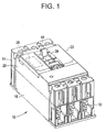
- Molded case circuit breaker 10 is generally interconnected within a protected circuit between multiple phases of a power source (not shown) at line end 14 and a load to be protected (not shown) at load end 12.
- Molded case circuit breaker 10 includes a base 18, a mid cover 20 and a top cover 22 having a toggle handle 44 (operating handle) extending through an opening 24.
- Toggle handle 44 is interconnected with a circuit breaker operating mechanism 38 ( Figure 2) and allows for external operation of cassettes 32, 34 and 36.
- a switch 26 may be positioned within the mid cover 20 as shown in phantom, and interfaces with circuit breaker operating mechanism 38.
- the circuit breaker in FIG. 1 shows a typical three phase configuration, however, the present invention is not limited to this configuration but may be applied to other configurations, such as the typical one, two or four phase circuit breakers.
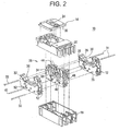
- FIG. 2 an exploded view of molded case circuit breaker 10 is provided.
- a series of circuit breaker cassettes 32, 34, 36 are generally well known and may be, for example, of the rotary type. Examples of rotary contact structures that may be operated by operating mechanism 38 are described in more detail in U.S. Patent Numbers 6,114,641 and 6,396,369, both entitled “Rotary Contact Assembly For High-Ampere Rated Circuit Breakers", and U.S. Patent Number 6,175,288, entitled “Supplemental Trip Unit For Rotary Circuit Interrupters”.
- Circuit breaker cassettes 32, 34, 36 are seated approximately upstanding within base 18, and the cassette 34 includes operating mechanism 38 positioned thereon.
- the individual phases of current are divided into three phases, wherein each phase passes through one of the circuit breaker cassettes 32, 34, 36.
- Each of cassettes 32, 34, 36 includes one or more contact pairs therein for passage of current when the contacts are closed and for preventing passage of current when the contact pairs are opened. It is contemplated that the number of phases, or specific type of cassette utilized, can vary according to factors including, but not limited to, the type of load circuit being protected and the type of line input being provided to the circuit breaker 10.
- each cassette 32, 34, 36 is commonly operated by a first cross bar (cross pin) 40 that interfaces with the internal mechanisms of cassettes 32, 34, 36 such that when one of cassettes 32, 34, 36 are opened or closed, the other cassettes 32, 34, 36 will operate cooperatively.
- first cross bar cross pin
- cross pin cross pin
- Only one cross bar may be used to interface with the internal mechanisms of cassettes 32, 34, 36 such that when one of cassettes 32, 34, 36 are opened or closed, the other cassettes 32, 34, 36 will operate cooperatively.
- Positioning rods 33 and protrusions 35 in cassettes 32, 36 are also employed to position the cassettes 32, 34, 36 adjacent to each other.
- Positioning rods 31 are also used to position mechanism 38 to locate cross bar 40 to align with rotary contact assembly 56 within cassettes 32, 34, 36.
- Operating mechanism 38 is positioned and configured atop cassette 34, which is generally disposed intermediate to cassettes 32 and 36. Operating mechanism 38 operates substantially as described herein and as described in U.S. Patent Application Number 6,218,919, entitled “Circuit Breaker Latch Mechanism with Decreased Trip Time”. It should also be noted that employment of other operating mechanisms is contemplated, as well.
- the cassettes 32, 34, 36 are typically formed of high strength plastic material and each include opposing sidewalls.
- Rotary contact assembly 56 includes a load side contact strap 58 and line side contact strap 62 for connection with a power source and a protected circuit (not shown), respectively.
- Load side contact strap 58 includes a stationary contact 64 and line side contact strap 62 includes a stationary contact 66.
- Rotary contact assembly 56 further includes a movable contact arm 68 having a set of contacts 72 and 74 that mate with stationary contacts 64 and 66, respectively.
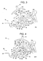
- toggle handle 44 In the "on” position ( Figure 3) of operating mechanism 38, wherein toggle handle 44 is oriented to the left as depicted in Figure 4 (e.g., via a manual or mechanical force), contacts 72 and 74 are mated with stationary contacts 64 and 66, thereby allowing current to flow through contact arm 68.
- toggle handle 44 In the "welded" position ( Figure 5) of operating mechanism 38, toggle handle 44 is attempted to be oriented between the "on” position and the "off” position (typically by either the release of mechanism springs within operating mechanism 38 or manipulation of handle 44 to the "off” position, described in greater detail herein).
- Contact arm 68 is mounted on a rotor structure 76 that houses one or more sets of contact springs (not shown). Contact arm 68 and rotor structure 76 pivot about a common center 78. Cross pin 40 interfaces through an opening 82 within rotor structure 76 generally to cause contact arm 68 to be moved from the "on", “off” and “tripped” position.
- operating mechanism 38 As viewed in Figure 3, operating mechanism 38 is in the closed or "on" position after being reset. Operating mechanism 38 has operating mechanism side frames 86 configured and positioned to straddle sidewalls 46, 48 of cassette 34 ( Figure 2).
- Toggle handle 44 is rigidly interconnected with a drive member or handle yoke 88.
- Handle yoke 88 includes opposing side portions (only one shown) 89.
- Each side portion 89 includes a U-shaped portion 92 at the bottom portion of each side portion 89.
- U-shaped portions 92 are rotatably positioned on a pair of bearing portions 94 protruding outwardly from side frames 86.
- Operating mechanism 38 has a pair of cranks 208 operably connected to a cradle 210. Examples of rotary contact structures having such a cradle that may be operated by operating mechanism 38 are described in more detail in U.S. Patent Application Serial Numbers 09/795,017 (GE Docket Number 41 PR-7850). Each crank 208 pivots about a center 78. Crank 208 has an opening corresponding with opening 82 within rotor structure 76 where a cross pin 40 ( Figure 2) passes through into arcuate passage 52 of cassettes 32, 34 and 36 ( Figure 2).
- cradle 210 is disposed adjacent to corresponding side frames 86 and pivots with respect to a cradle pivot pin 201 disposed through a corresponding opening (not shown) disposed in cradle 210.
- Cradle 210 includes a top edge surface including a cradle latch surface 164 disposed at one end thereof.
- Upper link pivot pin 200 is pivotally connected to the cradle 210 and to an upper link 211 that is pivotally connected to a lower link 212 at an opposite end via a rivet or toggle pin 214.
- An opposite end of lower link 212 in turn is pivotally coupled to crank 208 via a pin 218.
- a primary latch 126 is positioned within side frame 86.
- a secondary latch 138 is pivotally positioned within side frames 86.
- Secondary latch 138 extends from operating mechanism 38 as to allow an interface with, for example, a shunt trip (not shown), or a thermal magnetic trip unit (not shown) to release the engagement between primary latch 126 and secondary latch 138 thereby causing operating mechanism 38 to move to the "tripped" position (in Figure 6), described below.
- Secondary latch 138 includes a latch surface generally shown at 139 that aligns with a corresponding primary latch surface to release primary latch 126.
- secondary latch 138 has been displaced (e.g., by a thermal magnetic trip unit not shown) when secondary latch 138 pivots clockwise about a trip lever pin 140, and the interface between primary latch 126 and secondary latch 138 is released.
- the primary latch 126 is disengaged from cradle latch surface 164 (e.g., by rotating clockwise), and cradle 210 is rotated counter-clockwise about the cradle pivot pin 201 (shown in Figure 6).
- the movement of cradle 210 transmits a force to crank 208 via pin 200 corresponding to upper link 211 connected to lower link 212 with corresponding rivet 214 (as best seen with reference to Figure 5 and shown with phantom lines in Figures 3, 4, and 6), the lower link 212 causing crank 208 to rotate counter clockwise about center 78 and drive cross pin 40 to an upper portion of the arcuate passage 52 configured in the cassette.
- the forces transmitted through cross pin 40 to rotary contact assembly 56 via opening 52 cause movable contacts 72, 74 to separate from stationary contacts 64, 66 (see Figures 4 and 6), unless the movable contacts 72, 74 become welded to stationary contacts 64, 66 (see Figure 5).
- toggle pin 214 connects the toggle linkage 211, 212 with the mechanism spring 216.
- the force generated by the movement of the handle 44 will cause the toggle linkage 211, 212 to extend or collapse, which in turn results in the circuit breaker turning ON or OFF depending on the movement of the handle 44.
- the upper link 211 of the toggle linkage attaches to cradle 210 at pin 200.
- the lower link 212 attaches to crank 208 via pin 218.
- the crank 208 pivots on pin 78 attached to the side frames 86 and connects with a multi-pole rotary contact system 56 via pin 40.
- the rotary contact system operates in substantially the same manner as that described in U.S. patent application titled "Circuit Breaker Mechanism for a Rotary Contact Assembly" Ser. No. 09/196,706 filed on Nov. 20, 1998 which is incorporated herein by reference.
- the crank 208 includes a blocking lever 220 extending therefrom. Under certain operations, the blocking lever 220 interacts with a handle yoke projection 222 (as best seen with reference to Figure 5). The importance of the interaction between the lever projection 220 and the handle yoke projection 222 will be made clearer herein.
- the contacts 64, 66, 72, or 74 may become welded together. This welded condition prevents the mechanism 38 from separating the contacts 64, 66, 72, 74 as described above to disconnect the protected circuit.
- Certain quasi-regulatory agencies such as the International Electrotechnical Commission (IEC) require that the mechanism handle 44 be prevented from moving to the OFF position while the contacts 64, 66, 72, 74 are welded.
- the present invention configures blocking lever 220 extending from crank 208 to interfere with the handle yoke projection 222 extending from handle yoke 88 to prevent the handle 44 from being placed in the OFF position and if the handle 44 is moved, it will automatically return to the ON position when the handle 44 is released.
- the crank 208 When the contacts 64, 66, 72, 74 are welded, the crank 208 will stay in the closed position shown in Figure 5. If the user attempts to reset the breaker, the handle yoke 88 rotates until the yoke projection 222 contacts the mating surface of the blocking lever 220. Unlike the above situation, where the bias on the blocking lever 220 allowed the blocking lever 220 to rotate out of the path of the handle yoke projection 222, the blocking lever is motionless as it is extends from crank 208 which in turn is operably connected to the rotor arm assembly 56 having welded contacts 64, 66, 72, 74. Thus, the blocking lever 220 is prevented from rotating clockwise.
- a method and mechanical means is provided to prevent a user from moving the handle to the OFF or RESET position and possibly padlocking the handle in this position in the event that a contact becomes welded.
- the above-described method and mechanical means provides a cost effective means to employ handle blocking in a circuit breaker. More specifically, the above-described method and mechanical means for handle blocking is accomplished by modifying one component of the operating mechanism and one of the components of the rotary arm assembly for engagement therebetween in the event of welded contacts, thereby preventing movement of the handle to the OFF or RESET positions.
Landscapes
- Breakers (AREA)
Abstract
Description
Claims (10)
- A circuit breaker (10) comprising:a handle yoke (88) having a projection (222) extending therefrom, said handle yoke (88) being movable between an on position and an off position;a contact arm (68) supporting at least one contact (72, 74), said contact arm (68) being movable between a closed position and an open position; anda crank (208) operably coupled to said handle yoke (88) and said contact arm (68) to move said contact arm (68) from the closed position to the open position when said handle yoke (88) is moved from the on position to the off position, said crank (208) having a blocking lever (220) extending therefrom, said blocking lever (220) interacting with said projection (222) of said handle yoke (88) to prevent said handle yoke (88) from being moved to the off position when said contact arm (68) is fixed in the closed position.
- The circuit breaker (10) of claim 1, wherein:said projection (222) further comprises a first surface; andsaid blocking lever (220) further comprises a second surface cooperating with said first surface such that rotation of said blocking lever (220) when said contact arm (68) moves between the closed and open positions, without said blocking lever (220) interacting with said projection (222) of said handle yoke (88).
- The circuit breaker (10) of claim 2, wherein when said contact arm (68) is prevented from moving between closed and open positions, said second surface of said blocking lever (220) interacts with said first surface of said projection (222) of said handle (44) preventing movement of said handle yoke (88) to the off position.
- The circuit breaker (10) of claim 1, wherein said blocking lever (220) is integrally formed with said crank (208).
- The circuit breaker (10) of claim 1 wherein said at least one contact (72, 74) comprises a contact (72, 74) located at one end of said contact arm (68).
- The circuit breaker (10) of claim 1 wherein said at least one contact (72, 74) comprises a pair of contacts (72, 74), each of said contacts (72, 74) located at an opposing end of said contact arm (68).
- The circuit breaker (10) of claim 1 further comprising:a cradle (210);a toggle linkage having an upper link (211) and a lower link (212), said upper link (211) being pivotally attached to said cradle (210) at one end and to a toggle pivot at an opposite end, said lower link (212) being pivotally attached to said toggle pivot at one end and to said crank (208) at an opposite end; anda spring (216) connected between said toggle pivot and said handle yoke (88) to bias said crank (208) in a direction for moving said contact arm (68) to an open position when said handle yoke (88) is moved from an off to on position.
- The circuit breaker (10) of claim 7 wherein:said crank (208) and said contact arm (68) rotate on a common axis (78) andsaid crank (208) is coupled to said lower link (212) at a first pin (218) and said crank (208) is coupled to said contact arm (68) by a second pin (40), said second pin (40) being offset from said axis (78).
- The circuit breaker (10) of claim 8 wherein said second pin (40) is diametrically opposed to said first pin (218).
- The circuit breaker (10) of claim 8 wherein said blocking lever (220) extends from said crank (208) opposite said first pin (218) with said common axis (78) therebetween.
Applications Claiming Priority (2)
| Application Number | Priority Date | Filing Date | Title |
|---|---|---|---|
| US605124 | 2003-09-10 | ||
| US10/605,124 US6985059B2 (en) | 2003-09-10 | 2003-09-10 | Circuit breaker handle block |
Publications (3)
| Publication Number | Publication Date |
|---|---|
| EP1515351A2 true EP1515351A2 (en) | 2005-03-16 |
| EP1515351A3 EP1515351A3 (en) | 2007-05-02 |
| EP1515351B1 EP1515351B1 (en) | 2014-07-02 |
Family
ID=34135447
Family Applications (1)
| Application Number | Title | Priority Date | Filing Date |
|---|---|---|---|
| EP04255493.1A Expired - Lifetime EP1515351B1 (en) | 2003-09-10 | 2004-09-10 | Circuit breaker handle block |
Country Status (2)
| Country | Link |
|---|---|
| US (1) | US6985059B2 (en) |
| EP (1) | EP1515351B1 (en) |
Cited By (1)
| Publication number | Priority date | Publication date | Assignee | Title |
|---|---|---|---|---|
| DE102012203042A1 (en) * | 2012-02-28 | 2013-08-29 | Siemens Aktiengesellschaft | switching device |
Families Citing this family (11)
| Publication number | Priority date | Publication date | Assignee | Title |
|---|---|---|---|---|
| US7199319B1 (en) * | 2005-10-19 | 2007-04-03 | Eaton Corporation | Handle assembly having an integral slider therefor and electrical switching apparatus employing the same |
| KR200419048Y1 (en) | 2006-03-17 | 2006-06-16 | 엘에스산전 주식회사 | Circuit breaker |
| ATE531059T1 (en) * | 2006-10-31 | 2011-11-15 | Linak As | MOTOR ACTUATOR FOR A SWITCHGEAR FOR POWER NETWORK SYSTEMS |
| US20080172120A1 (en) * | 2007-01-12 | 2008-07-17 | Calvin Fenn | Endoprosthesis delivery systems and related methods |
| EP2023365B1 (en) * | 2007-08-10 | 2015-09-16 | LS Industrial Systems Co., Ltd | Molded case circuit breaker with contact on mechanism |
| DE102009048671A1 (en) * | 2009-09-30 | 2011-03-31 | Siemens Aktiengesellschaft | Arrangement with at least two separate Schaltpolgehäusen and with a connecting device for connecting the Schaltpolgehäuse and multi-pole electrical switching device with such an arrangement |
| KR101326987B1 (en) * | 2011-12-16 | 2013-11-13 | 현대중공업 주식회사 | Tripping device and a circuit braker having the same |
| EP2826050B1 (en) * | 2012-03-12 | 2017-04-26 | Siemens Aktiengesellschaft | Circuit breaker trip blocking apparatus, systems and methods of operation |
| EP3048632B1 (en) * | 2015-01-20 | 2017-08-16 | Siemens Aktiengesellschaft | Method for operating a circuit breaker and circuit breaker |
| KR101749981B1 (en) | 2016-02-12 | 2017-06-22 | 엘에스산전 주식회사 | Multi-Pole Molded Case Circuit Breaker |
| US9859083B1 (en) * | 2016-08-02 | 2018-01-02 | Siemens Aktiengesellschaft | Linkage-based off-stop apparatus and methods for circuit breakers |
Family Cites Families (14)
| Publication number | Priority date | Publication date | Assignee | Title |
|---|---|---|---|---|
| US5200724A (en) | 1989-03-30 | 1993-04-06 | Westinghouse Electric Corp. | Electrical circuit breaker operating handle block |
| US4951019A (en) * | 1989-03-30 | 1990-08-21 | Westinghouse Electric Corp. | Electrical circuit breaker operating handle block |
| US5184717A (en) * | 1991-05-29 | 1993-02-09 | Westinghouse Electric Corp. | Circuit breaker with welded contacts |
| US5296664A (en) * | 1992-11-16 | 1994-03-22 | Westinghouse Electric Corp. | Circuit breaker with positive off protection |
| DE9401785U1 (en) * | 1994-02-03 | 1995-07-20 | Klöckner-Moeller GmbH, 53115 Bonn | Key switch with a locking mechanism |
| US5874699A (en) * | 1997-09-18 | 1999-02-23 | Eaton Corporation | Molded case circuit breaker and moving conductor assembly therefor |
| US6114641A (en) | 1998-05-29 | 2000-09-05 | General Electric Company | Rotary contact assembly for high ampere-rated circuit breakers |
| US6087913A (en) | 1998-11-20 | 2000-07-11 | General Electric Company | Circuit breaker mechanism for a rotary contact system |
| US6166344A (en) * | 1999-03-23 | 2000-12-26 | General Electric Company | Circuit breaker handle block |
| US6175288B1 (en) | 1999-08-27 | 2001-01-16 | General Electric Company | Supplemental trip unit for rotary circuit interrupters |
| US6396369B1 (en) | 1999-08-27 | 2002-05-28 | General Electric Company | Rotary contact assembly for high ampere-rated circuit breakers |
| US6222143B1 (en) * | 2000-02-18 | 2001-04-24 | Siemens Energy & Automation, Inc. | Positive off toggle mechanism |
| US6218919B1 (en) | 2000-03-15 | 2001-04-17 | General Electric Company | Circuit breaker latch mechanism with decreased trip time |
| DE10129498C1 (en) * | 2001-06-19 | 2003-03-06 | Moeller Gmbh | Multi-pole electrical switching device with switch lock |
-
2003
- 2003-09-10 US US10/605,124 patent/US6985059B2/en not_active Expired - Lifetime
-
2004
- 2004-09-10 EP EP04255493.1A patent/EP1515351B1/en not_active Expired - Lifetime
Cited By (5)
| Publication number | Priority date | Publication date | Assignee | Title |
|---|---|---|---|---|
| DE102012203042A1 (en) * | 2012-02-28 | 2013-08-29 | Siemens Aktiengesellschaft | switching device |
| CN103295808A (en) * | 2012-02-28 | 2013-09-11 | 西门子公司 | Switching apparatus |
| US8993912B2 (en) | 2012-02-28 | 2015-03-31 | Siemens Aktiengesellschaft | Switching apparatus |
| CN103295808B (en) * | 2012-02-28 | 2016-12-28 | 西门子公司 | Switching device |
| DE102012203042B4 (en) | 2012-02-28 | 2024-01-25 | Siemens Aktiengesellschaft | Switching device and electrical switching device |
Also Published As
| Publication number | Publication date |
|---|---|
| EP1515351A3 (en) | 2007-05-02 |
| US20050051414A1 (en) | 2005-03-10 |
| US6985059B2 (en) | 2006-01-10 |
| EP1515351B1 (en) | 2014-07-02 |
Similar Documents
| Publication | Publication Date | Title |
|---|---|---|
| EP1039499B1 (en) | Circuit breaker handle block | |
| CA2242066C (en) | Rotary contact assembly for high ampere-rated circuit breakers | |
| EP1000431B1 (en) | Rotary contact assembly for high ampere-rated circuit breakers | |
| EP1183703B1 (en) | High energy closing mechanism for circuit breakers | |
| EP1208576B1 (en) | Trip override for a rotary breaker | |
| EP1515351B1 (en) | Circuit breaker handle block | |
| US6700467B2 (en) | Circuit interrupter operating mechanism | |
| EP1358663B1 (en) | Compact high speed motor operator for a circuit breaker | |
| US6084489A (en) | Circuit breaker rotary contact assembly locking system | |
| US6590482B2 (en) | Circuit breaker mechanism tripping cam | |
| US6778048B1 (en) | Circuit breaker interface mechanism for bell alarm switch | |
| US20020158732A1 (en) | Electronic trip unit interlock for circuit breakers | |
| US6380829B1 (en) | Motor operator interlock and method for circuit breakers | |
| US6806800B1 (en) | Assembly for mounting a motor operator on a circuit breaker | |
| JP3814671B2 (en) | Circuit breaker | |
| US6903635B2 (en) | Circuit breaker interface mechanism for auxiliary switch accessory | |
| EP1194941B1 (en) | Return spring for a circuit interrupter operating mechanism | |
| US6476337B2 (en) | Auxiliary switch actuation arrangement | |
| JPS5911170B2 (en) | Multipolar circuit breaker | |
| CA2042278C (en) | Circuit breaker positive trip indication spring | |
| EP1160818B1 (en) | Circuit breaker | |
| JP2738773B2 (en) | Circuit breaker | |
| US5023582A (en) | Molded case circuit breaker compact latch asssembly | |
| KR200382138Y1 (en) | A Mould Cased Circuit Breaker | |
| JPH0311052B2 (en) |
Legal Events
| Date | Code | Title | Description |
|---|---|---|---|
| PUAI | Public reference made under article 153(3) epc to a published international application that has entered the european phase |
Free format text: ORIGINAL CODE: 0009012 |
|
| AK | Designated contracting states |
Kind code of ref document: A2 Designated state(s): AT BE BG CH CY CZ DE DK EE ES FI FR GB GR HU IE IT LI LU MC NL PL PT RO SE SI SK TR |
|
| AX | Request for extension of the european patent |
Extension state: AL HR LT LV MK |
|
| RIN1 | Information on inventor provided before grant (corrected) |
Inventor name: LAFFERTY, PAUL DOUGLAS Inventor name: BRIGNONI, LUIS Inventor name: SUBRAMANIAN, ANANTHRAMJOHN F. WELCH TECH. CENTRE Inventor name: MACHA, NARENDER Inventor name: CIARCIA, RONALD |
|
| PUAL | Search report despatched |
Free format text: ORIGINAL CODE: 0009013 |
|
| AK | Designated contracting states |
Kind code of ref document: A3 Designated state(s): AT BE BG CH CY CZ DE DK EE ES FI FR GB GR HU IE IT LI LU MC NL PL PT RO SE SI SK TR |
|
| AX | Request for extension of the european patent |
Extension state: AL HR LT LV MK |
|
| RIN1 | Information on inventor provided before grant (corrected) |
Inventor name: CIARCIA, RONALD Inventor name: BRIGNONI, LUIS Inventor name: LAFFERTY, PAUL DOUGLAS Inventor name: SUBRAMANIAN, ANANTHRAMJOHN F. WELCH TECH. CENTRE Inventor name: MACHA, NARENDER |
|
| 17P | Request for examination filed |
Effective date: 20071102 |
|
| AKX | Designation fees paid |
Designated state(s): AT BE BG CH CY CZ DE DK EE ES FI FR GB GR HU IE IT LI LU MC NL PL PT RO SE SI SK TR |
|
| 17Q | First examination report despatched |
Effective date: 20100308 |
|
| GRAP | Despatch of communication of intention to grant a patent |
Free format text: ORIGINAL CODE: EPIDOSNIGR1 |
|
| INTG | Intention to grant announced |
Effective date: 20140228 |
|
| GRAS | Grant fee paid |
Free format text: ORIGINAL CODE: EPIDOSNIGR3 |
|
| GRAA | (expected) grant |
Free format text: ORIGINAL CODE: 0009210 |
|
| AK | Designated contracting states |
Kind code of ref document: B1 Designated state(s): AT BE BG CH CY CZ DE DK EE ES FI FR GB GR HU IE IT LI LU MC NL PL PT RO SE SI SK TR |
|
| REG | Reference to a national code |
Ref country code: GB Ref legal event code: FG4D |
|
| REG | Reference to a national code |
Ref country code: CH Ref legal event code: EP |
|
| REG | Reference to a national code |
Ref country code: IE Ref legal event code: FG4D |
|
| REG | Reference to a national code |
Ref country code: DE Ref legal event code: R096 Ref document number: 602004045424 Country of ref document: DE Effective date: 20140821 |
|
| REG | Reference to a national code |
Ref country code: NL Ref legal event code: VDEP Effective date: 20140702 |
|
| PGFP | Annual fee paid to national office [announced via postgrant information from national office to epo] |
Ref country code: FR Payment date: 20140917 Year of fee payment: 11 |
|
| REG | Reference to a national code |
Ref country code: AT Ref legal event code: REF Ref document number: 700041 Country of ref document: AT Kind code of ref document: T Effective date: 20141215 |
|
| PG25 | Lapsed in a contracting state [announced via postgrant information from national office to epo] |
Ref country code: FI Free format text: LAPSE BECAUSE OF FAILURE TO SUBMIT A TRANSLATION OF THE DESCRIPTION OR TO PAY THE FEE WITHIN THE PRESCRIBED TIME-LIMIT Effective date: 20140702 Ref country code: GR Free format text: LAPSE BECAUSE OF FAILURE TO SUBMIT A TRANSLATION OF THE DESCRIPTION OR TO PAY THE FEE WITHIN THE PRESCRIBED TIME-LIMIT Effective date: 20141003 Ref country code: SE Free format text: LAPSE BECAUSE OF FAILURE TO SUBMIT A TRANSLATION OF THE DESCRIPTION OR TO PAY THE FEE WITHIN THE PRESCRIBED TIME-LIMIT Effective date: 20140702 Ref country code: CZ Free format text: LAPSE BECAUSE OF FAILURE TO SUBMIT A TRANSLATION OF THE DESCRIPTION OR TO PAY THE FEE WITHIN THE PRESCRIBED TIME-LIMIT Effective date: 20140702 Ref country code: PT Free format text: LAPSE BECAUSE OF FAILURE TO SUBMIT A TRANSLATION OF THE DESCRIPTION OR TO PAY THE FEE WITHIN THE PRESCRIBED TIME-LIMIT Effective date: 20141103 Ref country code: BG Free format text: LAPSE BECAUSE OF FAILURE TO SUBMIT A TRANSLATION OF THE DESCRIPTION OR TO PAY THE FEE WITHIN THE PRESCRIBED TIME-LIMIT Effective date: 20141002 |
|
| PG25 | Lapsed in a contracting state [announced via postgrant information from national office to epo] |
Ref country code: NL Free format text: LAPSE BECAUSE OF FAILURE TO SUBMIT A TRANSLATION OF THE DESCRIPTION OR TO PAY THE FEE WITHIN THE PRESCRIBED TIME-LIMIT Effective date: 20140702 Ref country code: CY Free format text: LAPSE BECAUSE OF FAILURE TO SUBMIT A TRANSLATION OF THE DESCRIPTION OR TO PAY THE FEE WITHIN THE PRESCRIBED TIME-LIMIT Effective date: 20140702 Ref country code: PL Free format text: LAPSE BECAUSE OF FAILURE TO SUBMIT A TRANSLATION OF THE DESCRIPTION OR TO PAY THE FEE WITHIN THE PRESCRIBED TIME-LIMIT Effective date: 20140702 |
|
| REG | Reference to a national code |
Ref country code: AT Ref legal event code: MK05 Ref document number: 700041 Country of ref document: AT Kind code of ref document: T Effective date: 20140702 |
|
| REG | Reference to a national code |
Ref country code: DE Ref legal event code: R097 Ref document number: 602004045424 Country of ref document: DE |
|
| PG25 | Lapsed in a contracting state [announced via postgrant information from national office to epo] |
Ref country code: IT Free format text: LAPSE BECAUSE OF FAILURE TO SUBMIT A TRANSLATION OF THE DESCRIPTION OR TO PAY THE FEE WITHIN THE PRESCRIBED TIME-LIMIT Effective date: 20140702 Ref country code: LU Free format text: LAPSE BECAUSE OF FAILURE TO SUBMIT A TRANSLATION OF THE DESCRIPTION OR TO PAY THE FEE WITHIN THE PRESCRIBED TIME-LIMIT Effective date: 20140910 Ref country code: RO Free format text: LAPSE BECAUSE OF FAILURE TO SUBMIT A TRANSLATION OF THE DESCRIPTION OR TO PAY THE FEE WITHIN THE PRESCRIBED TIME-LIMIT Effective date: 20140702 Ref country code: EE Free format text: LAPSE BECAUSE OF FAILURE TO SUBMIT A TRANSLATION OF THE DESCRIPTION OR TO PAY THE FEE WITHIN THE PRESCRIBED TIME-LIMIT Effective date: 20140702 Ref country code: SK Free format text: LAPSE BECAUSE OF FAILURE TO SUBMIT A TRANSLATION OF THE DESCRIPTION OR TO PAY THE FEE WITHIN THE PRESCRIBED TIME-LIMIT Effective date: 20140702 Ref country code: DK Free format text: LAPSE BECAUSE OF FAILURE TO SUBMIT A TRANSLATION OF THE DESCRIPTION OR TO PAY THE FEE WITHIN THE PRESCRIBED TIME-LIMIT Effective date: 20140702 Ref country code: MC Free format text: LAPSE BECAUSE OF FAILURE TO SUBMIT A TRANSLATION OF THE DESCRIPTION OR TO PAY THE FEE WITHIN THE PRESCRIBED TIME-LIMIT Effective date: 20140702 |
|
| REG | Reference to a national code |
Ref country code: CH Ref legal event code: PL |
|
| PLBE | No opposition filed within time limit |
Free format text: ORIGINAL CODE: 0009261 |
|
| STAA | Information on the status of an ep patent application or granted ep patent |
Free format text: STATUS: NO OPPOSITION FILED WITHIN TIME LIMIT |
|
| PG25 | Lapsed in a contracting state [announced via postgrant information from national office to epo] |
Ref country code: AT Free format text: LAPSE BECAUSE OF FAILURE TO SUBMIT A TRANSLATION OF THE DESCRIPTION OR TO PAY THE FEE WITHIN THE PRESCRIBED TIME-LIMIT Effective date: 20140702 |
|
| 26N | No opposition filed |
Effective date: 20150407 |
|
| REG | Reference to a national code |
Ref country code: IE Ref legal event code: MM4A |
|
| GBPC | Gb: european patent ceased through non-payment of renewal fee |
Effective date: 20141002 |
|
| PG25 | Lapsed in a contracting state [announced via postgrant information from national office to epo] |
Ref country code: BE Free format text: LAPSE BECAUSE OF NON-PAYMENT OF DUE FEES Effective date: 20140930 |
|
| PG25 | Lapsed in a contracting state [announced via postgrant information from national office to epo] |
Ref country code: CH Free format text: LAPSE BECAUSE OF NON-PAYMENT OF DUE FEES Effective date: 20140930 Ref country code: GB Free format text: LAPSE BECAUSE OF NON-PAYMENT OF DUE FEES Effective date: 20141002 Ref country code: LI Free format text: LAPSE BECAUSE OF NON-PAYMENT OF DUE FEES Effective date: 20140930 |
|
| PG25 | Lapsed in a contracting state [announced via postgrant information from national office to epo] |
Ref country code: IE Free format text: LAPSE BECAUSE OF NON-PAYMENT OF DUE FEES Effective date: 20140910 |
|
| PG25 | Lapsed in a contracting state [announced via postgrant information from national office to epo] |
Ref country code: SI Free format text: LAPSE BECAUSE OF FAILURE TO SUBMIT A TRANSLATION OF THE DESCRIPTION OR TO PAY THE FEE WITHIN THE PRESCRIBED TIME-LIMIT Effective date: 20140702 |
|
| REG | Reference to a national code |
Ref country code: FR Ref legal event code: ST Effective date: 20160531 |
|
| PG25 | Lapsed in a contracting state [announced via postgrant information from national office to epo] |
Ref country code: BE Free format text: LAPSE BECAUSE OF FAILURE TO SUBMIT A TRANSLATION OF THE DESCRIPTION OR TO PAY THE FEE WITHIN THE PRESCRIBED TIME-LIMIT Effective date: 20140702 Ref country code: TR Free format text: LAPSE BECAUSE OF FAILURE TO SUBMIT A TRANSLATION OF THE DESCRIPTION OR TO PAY THE FEE WITHIN THE PRESCRIBED TIME-LIMIT Effective date: 20140702 Ref country code: HU Free format text: LAPSE BECAUSE OF FAILURE TO SUBMIT A TRANSLATION OF THE DESCRIPTION OR TO PAY THE FEE WITHIN THE PRESCRIBED TIME-LIMIT; INVALID AB INITIO Effective date: 20040910 |
|
| PG25 | Lapsed in a contracting state [announced via postgrant information from national office to epo] |
Ref country code: FR Free format text: LAPSE BECAUSE OF NON-PAYMENT OF DUE FEES Effective date: 20150930 |
|
| PG25 | Lapsed in a contracting state [announced via postgrant information from national office to epo] |
Ref country code: ES Free format text: LAPSE BECAUSE OF NON-PAYMENT OF DUE FEES Effective date: 20140702 |
|
| PGFP | Annual fee paid to national office [announced via postgrant information from national office to epo] |
Ref country code: DE Payment date: 20181129 Year of fee payment: 15 |
|
| REG | Reference to a national code |
Ref country code: DE Ref legal event code: R119 Ref document number: 602004045424 Country of ref document: DE |
|
| PG25 | Lapsed in a contracting state [announced via postgrant information from national office to epo] |
Ref country code: DE Free format text: LAPSE BECAUSE OF NON-PAYMENT OF DUE FEES Effective date: 20200401 |