EP1515300A1 - Display color adjustment - Google Patents
Display color adjustment Download PDFInfo
- Publication number
- EP1515300A1 EP1515300A1 EP03368087A EP03368087A EP1515300A1 EP 1515300 A1 EP1515300 A1 EP 1515300A1 EP 03368087 A EP03368087 A EP 03368087A EP 03368087 A EP03368087 A EP 03368087A EP 1515300 A1 EP1515300 A1 EP 1515300A1
- Authority
- EP
- European Patent Office
- Prior art keywords
- color
- display
- adjust
- bits
- adjustment
- Prior art date
- Legal status (The legal status is an assumption and is not a legal conclusion. Google has not performed a legal analysis and makes no representation as to the accuracy of the status listed.)
- Withdrawn
Links
- 239000003086 colorant Substances 0.000 claims abstract description 47
- 238000000034 method Methods 0.000 claims abstract description 27
- 102000003668 Destrin Human genes 0.000 claims abstract 2
- 108090000082 Destrin Proteins 0.000 claims abstract 2
- 230000008859 change Effects 0.000 claims description 15
- 230000007423 decrease Effects 0.000 claims description 6
- 238000012546 transfer Methods 0.000 claims description 4
- 239000011159 matrix material Substances 0.000 description 8
- RRLHMJHRFMHVNM-BQVXCWBNSA-N [(2s,3r,6r)-6-[5-[5-hydroxy-3-(4-hydroxyphenyl)-4-oxochromen-7-yl]oxypentoxy]-2-methyl-3,6-dihydro-2h-pyran-3-yl] acetate Chemical compound C1=C[C@@H](OC(C)=O)[C@H](C)O[C@H]1OCCCCCOC1=CC(O)=C2C(=O)C(C=3C=CC(O)=CC=3)=COC2=C1 RRLHMJHRFMHVNM-BQVXCWBNSA-N 0.000 description 3
- 238000006243 chemical reaction Methods 0.000 description 3
- 238000010586 diagram Methods 0.000 description 2
- 238000012545 processing Methods 0.000 description 2
- 239000010409 thin film Substances 0.000 description 2
- 238000012512 characterization method Methods 0.000 description 1
- 238000012937 correction Methods 0.000 description 1
- 230000003247 decreasing effect Effects 0.000 description 1
- 230000006870 function Effects 0.000 description 1
- 239000000463 material Substances 0.000 description 1
- 230000004048 modification Effects 0.000 description 1
- 238000012986 modification Methods 0.000 description 1
- 230000009467 reduction Effects 0.000 description 1
Images


Classifications
-
- G—PHYSICS
- G09—EDUCATION; CRYPTOGRAPHY; DISPLAY; ADVERTISING; SEALS
- G09G—ARRANGEMENTS OR CIRCUITS FOR CONTROL OF INDICATING DEVICES USING STATIC MEANS TO PRESENT VARIABLE INFORMATION
- G09G3/00—Control arrangements or circuits, of interest only in connection with visual indicators other than cathode-ray tubes
- G09G3/20—Control arrangements or circuits, of interest only in connection with visual indicators other than cathode-ray tubes for presentation of an assembly of a number of characters, e.g. a page, by composing the assembly by combination of individual elements arranged in a matrix no fixed position being assigned to or needed to be assigned to the individual characters or partial characters
- G09G3/2092—Details of a display terminals using a flat panel, the details relating to the control arrangement of the display terminal and to the interfaces thereto
-
- G—PHYSICS
- G09—EDUCATION; CRYPTOGRAPHY; DISPLAY; ADVERTISING; SEALS
- G09G—ARRANGEMENTS OR CIRCUITS FOR CONTROL OF INDICATING DEVICES USING STATIC MEANS TO PRESENT VARIABLE INFORMATION
- G09G5/00—Control arrangements or circuits for visual indicators common to cathode-ray tube indicators and other visual indicators
- G09G5/02—Control arrangements or circuits for visual indicators common to cathode-ray tube indicators and other visual indicators characterised by the way in which colour is displayed
-
- G—PHYSICS
- G09—EDUCATION; CRYPTOGRAPHY; DISPLAY; ADVERTISING; SEALS
- G09G—ARRANGEMENTS OR CIRCUITS FOR CONTROL OF INDICATING DEVICES USING STATIC MEANS TO PRESENT VARIABLE INFORMATION
- G09G2320/00—Control of display operating conditions
- G09G2320/02—Improving the quality of display appearance
-
- G—PHYSICS
- G09—EDUCATION; CRYPTOGRAPHY; DISPLAY; ADVERTISING; SEALS
- G09G—ARRANGEMENTS OR CIRCUITS FOR CONTROL OF INDICATING DEVICES USING STATIC MEANS TO PRESENT VARIABLE INFORMATION
- G09G2320/00—Control of display operating conditions
- G09G2320/02—Improving the quality of display appearance
- G09G2320/0271—Adjustment of the gradation levels within the range of the gradation scale, e.g. by redistribution or clipping
- G09G2320/0276—Adjustment of the gradation levels within the range of the gradation scale, e.g. by redistribution or clipping for the purpose of adaptation to the characteristics of a display device, i.e. gamma correction
-
- G—PHYSICS
- G09—EDUCATION; CRYPTOGRAPHY; DISPLAY; ADVERTISING; SEALS
- G09G—ARRANGEMENTS OR CIRCUITS FOR CONTROL OF INDICATING DEVICES USING STATIC MEANS TO PRESENT VARIABLE INFORMATION
- G09G2320/00—Control of display operating conditions
- G09G2320/02—Improving the quality of display appearance
- G09G2320/0285—Improving the quality of display appearance using tables for spatial correction of display data
-
- G—PHYSICS
- G09—EDUCATION; CRYPTOGRAPHY; DISPLAY; ADVERTISING; SEALS
- G09G—ARRANGEMENTS OR CIRCUITS FOR CONTROL OF INDICATING DEVICES USING STATIC MEANS TO PRESENT VARIABLE INFORMATION
- G09G2360/00—Aspects of the architecture of display systems
- G09G2360/18—Use of a frame buffer in a display terminal, inclusive of the display panel
Definitions
- This invention relates generally to display systems, and more particularly to a system and a method to adjust colors to be displayed before writing it into a display RAM.
- the colors of digital images have to be normally adjusted to accommodate to the display system used to display said digital images. Without any adjustment a viewer of digital images will not be satisfied with the colors shown. All display systems such as e.g. color super twist nematic (CSTN), thin film transistor (TFT), organic light emitting diode (OLED), or double layer supertwist nematic (DSTN) displays have their specific flaws in displaying colors. Therefore the colors of digital images have to be adjusted to satisfy the expectations of the viewers of said images.
- CSTN color super twist nematic
- TFT thin film transistor
- OLED organic light emitting diode
- DSTN double layer supertwist nematic
- U. S. Patent 6,262,817 (to Sato et al.) describes a color image system for adjusting colors of inputted images including a color adjusting unit and color display unit.
- the color display unit simultaneously displays the original image, the adjusted image, and color information for both the original image and adjusted image.
- a color adjustment matrix is created by the color-adjusting unit based upon color directions inputted to the color display unit with respect to the color information of the original color image.
- the color adjustment matrix is used to directly adjust the original image without converting the image to a second color space.
- a color-adjusting unit produces a color adjustment matrix by adding color adjustment direction of the luminance, chroma, and hue, directed by the image display unit used, for the original matrix. After the color adjustment matrix being produced, the adjusted pixel can be produced by calculating the original pixel and the color adjustment matrix.
- U. S. Patent 6,388,648 discloses an LCD projection unit employing a luminance and color balance system employing an LCD array characterization lookup table storing multiple sets of luminance and gamma correction values that are user selectable to control luminance and color balance.
- the lookup table values are determined by measuring the transfer function of the LCD array in the projection unit for each of a set of red ("R"), green ("G"), and blue (“B") input data values, converting the resulting S-curve responses to corresponding sets of gamma responses and scaling the gamma responses to generate multiple R, G, and B families of luminance and gamma corrected values.
- Color balance is adjusted by selecting the particular R, G, and B families of luminance and gamma corrected values that cause the LCD projection unit to match a predetermined ratio of R, G, and B luminance values.
- Luminance is adjusted by selecting sets of families of R, G, and B, luminance values that maintain the color balance ratio while causing the LCD to transmit the desired overall luminance.
- the primary colors are adjusted by a method of color mixing implemented by a mathematical matrix algorithm that generates color modification coefficients for a color space conversion circuit.
- the primary color matching algorithm involves measuring the intrinsic colors coordinates of the primaries, determining a set of predetermined target coordinates, and performing matrix operations to calculate the coefficients used in the color space conversion circuit to convert the measured to the target coordinates, thereby matching the primary colors.
- the above-described color balance and luminance matching system adjusts the white and gray balance to result in a well-matched multiscreen display system.
- U. S. Patent 4,409,614 discloses a method wherein color scanning signals generated by scanning the original image are first converted into three primary color signals having actual color values in a predetermined color coordinate system corresponding substantially identically to theoretical color values of the original. It is only after this conversion that the primary signals or signals derived from these signals are converted to another color rendition system, or the gradation is altered, or the color rendition of individual colors in the overall image or in discrete areas is altered, or any other non-linear processing takes place.
- a principal object of the present invention is to linearly scale the colors of display data.
- a further object of the present invention is to achieve a cost effective solution for the scaling of the colors of display data.
- Another further object of the invention is to achieve a very fast processing of the adjustment of the colors of display data.
- Said system comprises a color screen used as a display using primary colors of a color space, a system processor sending downloading display data to a display driver circuit, and a display driver circuit.
- Said display driver circuit comprises a processor interface logic providing the interface between said system processor and said display driver circuit, a display adjust circuit adjusting the display data received from said system processor via said processor interface logic and writing said modified display data into a display RAM, one or more color adjust registers, a display RAM for storing the adjusted display data, and a screen driver controlling said screen and sending said adjusted display data to said screen.
- Said method comprises, first, providing a display screen, a system processor, and a display driver circuit comprising a processor interface logic, a display adjust circuit, one or more color adjust registers, a display RAM and a screen driver circuit.
- the steps of said method are to define adjustment data for each primary color used by said display screen to adjust said colors according to the properties of said screen, to store said adjustment data for each primary color in one or more registers providing one or more bits for each primary color, to define a word structure to operate the unadjusted display data and to store the adjusted display data in a display RAM wherein for each primary color a defined number of bits is assigned, and to implement an algorithm to adjust each of the primary colors, used by said screen, in said display adjust circuit using a hardware description language.
- the preferred embodiments disclose a system and a method to linearly scale display data before it is written into a display RAM.
- the embodiments of the present invention are applicable to any electronic display types, such as e.g. color super twist nematic (CSTN), thin film transistor (TFT), organic light emitting (OLED), or double layer supertwist nematic (DSTN) displays.
- CSTN color super twist nematic
- TFT thin film transistor
- OLED organic light emitting
- DSTN double layer supertwist nematic
- Fig. 1 shows a block diagram of a preferred embodiment of the present invention.
- the display system shows a display driver IC 1 , being key to the present invention.
- the system comprises a display 2 and a system processor 3 .
- said display 2 could be any type of display.
- Said display driver IC 1 is characterized, compared to prior art, by having a display adjust circuitry 6 which is receiving unadjusted display data from a processor interface logic 7 , adjusting said unadjusted display data using color adjust registers 8 for red, green, and blue, and writing the adjusted display data into a display RAM 5 , containing display data to be displayed on a screen display 2 .
- said system comprises a screen driver circuitry 4 , driving said screen display.
- the displayed colors can be adjusted by a simple integer multiplication of the color data value before writing into the display RAM 5 .
- a 65K color display has a 16-bit word split into a red, green and blue component.
- color displays using other color spaces besides RGB, e.g. CMY, could be used as well.
- the table below shows the word structure used in an embodiment of the present invention. Five bits are provided for red, six bits are provided for green and five bits are provided for blue in the 16-bit structure selected in said preferred embodiment. Using the word structure shown of the table below 32 different values of red, 64 different values of green and 32 different values of blue could be shown in case of unadjusted display data. This would result in having a palette of 32 ⁇ 64 ⁇ 32, this means 65536 different colors.
- 5-bit RED 6-bit GREEN 5-bit BLUE R4 R3 R2 R1 R0 G5 G4 G3 G2 G1 G0 B4 B3 B2 B1 B0
- Each color value is individually adjusted with its own setting, which allows maximum flexibility in display adjustment.
- the system processor 3 sets the red, green and blue color adjust register settings for the particular display (e.g. LCD, TFT, OLED).
- the display data is downloaded from the system processor 3 , the display color adjust circuitry 6 adjusts said display data before it is written into the display RAM 5 .
- the display data in a preferred embodiment is linearly scaled by a programmable amount.
- the multiplication factor is chosen to give a simple logic implementation.
- RED represented in 5 bits, depending upon the multiplication factor n, the related scaling factor, the mathematical equation used, the related percentage of change of RED, and the related number of colors that can be displayed. It is obvious, that the color BLUE, represented in 5 bits as well, has exact the same characteristics in regard of adjustment as RED shown in the table below. Therefore BLUE is not shown in a separate table.
- the table below shoes how the color RED could be decreased or increased depending upon the multiplication factor n and the positive or negative algebraic sign of the mathematical equation used It should be understood that the mathematical operations used can be performed extremely fast by simple operations of internal registers.
- the right-hand column shows how the number of different colors, which can be totally displayed, decreases upon the amount of increase/or decrease of RED. This reduction of the number of colors is caused by the mathematical operations (shift of registers) during the adjustment.
- the color BLUE has the identical values as RED shown in the table below.
- Scaling factor Mathematic equation Wherein n % change No.
- the table below shows the values of colors, being represented by 6 bits.
- GREEN is represented by 6 bits in a preferred embodiment of the invention.
- the table below shows the same columns as the table above. It is obvious that by using 6 bits, compared to 5 bits in the previous table, the adjustment can be performed in additional two steps (one step more each to increase or decrease the color value) and the numbers of different colors, which can be displayed is significantly higher.
- a palette of 65 536 different colors can be displayed using unadjusted color values.
- a typical adjustment comprises 0 % change of RED, +6 % change of GREEN, and 0% change of BLUE.
- 32 different values of RED 61 different values of GREEN and 32 different values of BLUE can be displayed. This would result in having a palette of 32 ⁇ 61 ⁇ 32, this means 62 464 different colors can be displayed.
- a rather severe adjustment could result in -12 % change of RED and BLUE and +6 % change of GREEN. This would result in having a palette of 29 ⁇ 61 ⁇ 29, this means 51301 different colors could still be displayed.
- the table below shows how the color adjust registers are used in a preferred embodiment of the present invention to store the color adjust information.
- two registers having 8 bits (B0 to B7) each are being used.
- register 1 the three bits B0 to B2 are used to store the red color adjustment data (RCA 2:0).
- the data for the blue color adjustment (BCA 2:0) are stored in the three bits B4 to B6 of register 1.
- the data for the green color adjustment (GCA 3:0) are stored in four bits B0 to B3 of register 2.
- the next table shows how in a preferred embodiment the three bits for the red color adjustment RCA (2:0) are used:
- the percentage values of the table below show the amount of increase/decrease of the color value of RED.
- 011 +25% (2-bit shift and add)
- 010 +12.5% (3-bit shift and add)
- 001 +6.3% (4-bit shift and add)
- 000 no change (default value)
- 101 -6.3% (4-bit shift and subtract)
- 110 -12.5% (3-bit shift and subtract)
- 111 -25% (2-bit shift and subtract)
- Green color adjustment GCA 3:0
- the bit arrangement for green color adjustment in a preferred embodiment of the present invention is as follows:
- RTL register transfer level code
- HDL Hardware Description Language
- Fig. 2 shows a related method to scale display data in a display driver circuit before it is written into a display RAM.
- the first step 21 of said method is to define adjustment data for each primary color used by said display screen to adjust said colors according to the properties of said screen.
- the following step 22 is to store said adjustment data for each primary color in one or more registers providing one or more bits for each primary color.
- Step 23 describes the definition of a word structure to operate the unadjusted display data and to store the adjusted data in a display RAM wherein for each primary color a defined number of bits is assigned.
- the next step 24 shows the implementation of an algorithm to adjust each of the primary colors, used by said screen, in said display adjust circuit using a hardware description language.
- step 25 the display data are downloaded from the system processor into the display adjust circuit, followed by step 26 in which the display data, adjusted in the display adjust circuit according to the algorithm implemented earlier and according to the adjustment data defined and stored earlier, are written into the display RAM.
- step 27 the adjusted display data are forwarded from the display RAM to the display screen by the screen driver circuit.
Landscapes
- Engineering & Computer Science (AREA)
- Physics & Mathematics (AREA)
- Computer Hardware Design (AREA)
- General Physics & Mathematics (AREA)
- Theoretical Computer Science (AREA)
- Control Of Indicators Other Than Cathode Ray Tubes (AREA)
- Electroluminescent Light Sources (AREA)
- Liquid Crystal Display Device Control (AREA)
- Controls And Circuits For Display Device (AREA)
- Control Of El Displays (AREA)
- Liquid Crystal (AREA)
Abstract
Description
- This invention relates generally to display systems, and more particularly to a system and a method to adjust colors to be displayed before writing it into a display RAM.
- The colors of digital images have to be normally adjusted to accommodate to the display system used to display said digital images. Without any adjustment a viewer of digital images will not be satisfied with the colors shown. All display systems such as e.g. color super twist nematic (CSTN), thin film transistor (TFT), organic light emitting diode (OLED), or double layer supertwist nematic (DSTN) displays have their specific flaws in displaying colors. Therefore the colors of digital images have to be adjusted to satisfy the expectations of the viewers of said images.
- There is a multitude of methods known to perform said color adjustment.
- U. S. Patent 6,262,817 (to Sato et al.) describes a color image system for adjusting colors of inputted images including a color adjusting unit and color display unit. The color display unit simultaneously displays the original image, the adjusted image, and color information for both the original image and adjusted image. A color adjustment matrix is created by the color-adjusting unit based upon color directions inputted to the color display unit with respect to the color information of the original color image. The color adjustment matrix is used to directly adjust the original image without converting the image to a second color space. A color-adjusting unit produces a color adjustment matrix by adding color adjustment direction of the luminance, chroma, and hue, directed by the image display unit used, for the original matrix. After the color adjustment matrix being produced, the adjusted pixel can be produced by calculating the original pixel and the color adjustment matrix.
- U. S. Patent 6,388,648 (to Clifton et al.) discloses an LCD projection unit employing a luminance and color balance system employing an LCD array characterization lookup table storing multiple sets of luminance and gamma correction values that are user selectable to control luminance and color balance. The lookup table values are determined by measuring the transfer function of the LCD array in the projection unit for each of a set of red ("R"), green ("G"), and blue ("B") input data values, converting the resulting S-curve responses to corresponding sets of gamma responses and scaling the gamma responses to generate multiple R, G, and B families of luminance and gamma corrected values. Color balance is adjusted by selecting the particular R, G, and B families of luminance and gamma corrected values that cause the LCD projection unit to match a predetermined ratio of R, G, and B luminance values. Luminance is adjusted by selecting sets of families of R, G, and B, luminance values that maintain the color balance ratio while causing the LCD to transmit the desired overall luminance. The primary colors are adjusted by a method of color mixing implemented by a mathematical matrix algorithm that generates color modification coefficients for a color space conversion circuit. The primary color matching algorithm involves measuring the intrinsic colors coordinates of the primaries, determining a set of predetermined target coordinates, and performing matrix operations to calculate the coefficients used in the color space conversion circuit to convert the measured to the target coordinates, thereby matching the primary colors. When the primary colors are matched, the above-described color balance and luminance matching system adjusts the white and gray balance to result in a well-matched multiscreen display system.
- U. S. Patent 4,409,614 (to Eichler et al.) discloses a method wherein color scanning signals generated by scanning the original image are first converted into three primary color signals having actual color values in a predetermined color coordinate system corresponding substantially identically to theoretical color values of the original. It is only after this conversion that the primary signals or signals derived from these signals are converted to another color rendition system, or the gradation is altered, or the color rendition of individual colors in the overall image or in discrete areas is altered, or any other non-linear processing takes place.
- A principal object of the present invention is to linearly scale the colors of display data.
- A further object of the present invention is to achieve a cost effective solution for the scaling of the colors of display data.
- Another further object of the invention is to achieve a very fast processing of the adjustment of the colors of display data.
- In accordance with the objects of this invention a system to adjust colors in any kind of electronic display has been achieved. Said system comprises a color screen used as a display using primary colors of a color space, a system processor sending downloading display data to a display driver circuit, and a display driver circuit. Said display driver circuit comprises a processor interface logic providing the interface between said system processor and said display driver circuit, a display adjust circuit adjusting the display data received from said system processor via said processor interface logic and writing said modified display data into a display RAM, one or more color adjust registers, a display RAM for storing the adjusted display data, and a screen driver controlling said screen and sending said adjusted display data to said screen.
- In accordance with the objects of the invention a method to adjust colors in any kind of electronic display has been invented. Said method comprises, first, providing a display screen, a system processor, and a display driver circuit comprising a processor interface logic, a display adjust circuit, one or more color adjust registers, a display RAM and a screen driver circuit. The steps of said method are to define adjustment data for each primary color used by said display screen to adjust said colors according to the properties of said screen, to store said adjustment data for each primary color in one or more registers providing one or more bits for each primary color, to define a word structure to operate the unadjusted display data and to store the adjusted display data in a display RAM wherein for each primary color a defined number of bits is assigned, and to implement an algorithm to adjust each of the primary colors, used by said screen, in said display adjust circuit using a hardware description language. These steps are followed by to download display data from system processor into display adjust circuit, to adjust display data in display adjust circuit according to algorithm implemented earlier and according adjustment data defined and stored earlier and write adjusted display data into display RAM, and to forward adjusted display data from the display RAM to the display screen by the screen driver circuit.
- In the accompanying drawings forming a material part of this description, there is shown:
- Fig. 1 illustrates in a block diagram the basic components of the system invented.
- Fig. 2 shows a flowchart of the method invented.
-
- The preferred embodiments disclose a system and a method to linearly scale display data before it is written into a display RAM. The embodiments of the present invention are applicable to any electronic display types, such as e.g. color super twist nematic (CSTN), thin film transistor (TFT), organic light emitting (OLED), or double layer supertwist nematic (DSTN) displays. Compared to prior art solutions the system and method invented provide a fast and very cost effective way to adjust colors of digital images according to color characteristics of the display type used.
- Fig. 1 shows a block diagram of a preferred embodiment of the present invention. The display system shows a
display driver IC 1, being key to the present invention. Furthermore the system comprises adisplay 2 and a system processor 3. As mentioned above, saiddisplay 2 could be any type of display. Saiddisplay driver IC 1 is characterized, compared to prior art, by having a display adjustcircuitry 6 which is receiving unadjusted display data from aprocessor interface logic 7, adjusting said unadjusted display data using color adjustregisters 8 for red, green, and blue, and writing the adjusted display data into a display RAM 5, containing display data to be displayed on ascreen display 2. Furthermore said system comprises ascreen driver circuitry 4, driving said screen display. - For those skilled in art it is obvious that the display driver circuit described above lends itself to an implementation in an ASIC circuit.
- The displayed colors can be adjusted by a simple integer multiplication of the color data value before writing into the display RAM 5. In a preferred embodiment a 65K color display has a 16-bit word split into a red, green and blue component. In other embodiments color displays using other color spaces besides RGB, e.g. CMY, could be used as well.
- The table below shows the word structure used in an embodiment of the present invention. Five bits are provided for red, six bits are provided for green and five bits are provided for blue in the 16-bit structure selected in said preferred embodiment. Using the word structure shown of the table below 32 different values of red, 64 different values of green and 32 different values of blue could be shown in case of unadjusted display data. This would result in having a palette of 32 × 64 × 32, this means 65536 different colors.
5-bit RED 6-bit GREEN 5-bit BLUE R4 R3 R2 R1 R0 G5 G4 G3 G2 G1 G0 B4 B3 B2 B1 B0 - Each color value is individually adjusted with its own setting, which allows maximum flexibility in display adjustment. The system processor 3 sets the red, green and blue color adjust register settings for the particular display (e.g. LCD, TFT, OLED). The display data is downloaded from the system processor 3, the display color adjust
circuitry 6 adjusts said display data before it is written into the display RAM 5. - The display data in a preferred embodiment is linearly scaled by a programmable amount. The multiplication factor is chosen to give a simple logic implementation.
- The table below shows for RED, represented in 5 bits, depending upon the multiplication factor n, the related scaling factor, the mathematical equation used, the related percentage of change of RED, and the related number of colors that can be displayed. It is obvious, that the color BLUE, represented in 5 bits as well, has exact the same characteristics in regard of adjustment as RED shown in the table below. Therefore BLUE is not shown in a separate table.
- The table below shoes how the color RED could be decreased or increased depending upon the multiplication factor n and the positive or negative algebraic sign of the mathematical equation used It should be understood that the mathematical operations used can be performed extremely fast by simple operations of internal registers.
The right-hand column shows how the number of different colors, which can be totally displayed, decreases upon the amount of increase/or decrease of RED. This reduction of the number of colors is caused by the mathematical operations (shift of registers) during the adjustment. Again, the color BLUE has the identical values as RED shown in the table below.Scaling factor Mathematic equation Wherein n= % change No. of colors RED x 3/4 RED - RED/2n 2 -25% 25 RED x 7/8 RED - RED/2n 3 -12.5% 29 RED x 15/16 RED - RED/2n 4 -6.3% 31 RED x 1 No change 0 32 RED x 17/16 RED + RED/2n 4 +6.3% 31 RED x 9/8 RED + RED/2n 3 +12.5% 29 RED x 5/4 RED + RED/2n 2 +25% 26 - If the result of the mathematic equation RED + RED/2n is greater than 31, the result is limited to 31 due to the 5-bit limit.
- The table below shows the values of colors, being represented by 6 bits. As explained earlier, GREEN is represented by 6 bits in a preferred embodiment of the invention. The table below shows the same columns as the table above. It is obvious that by using 6 bits, compared to 5 bits in the previous table, the adjustment can be performed in additional two steps (one step more each to increase or decrease the color value) and the numbers of different colors, which can be displayed is significantly higher.
Scaling factor Mathematic equation Wherein n= % change No. of colors GREEN x 3/4 GREEN - GREEN/2n 2 -25 % 49 GREEN x 7/8 GREEN - GREEN/2n 3 -12.5 % 57 GREEN x 15/16 GREEN - GREEN/2n 4 -6.3 % 61 GREEN x 31/32 GREEN - GREEN/2n 5 -3.1 % 63 GREEN x 1 No change 0 % 64 GREEN x 33/32 GREEN + GREEN/2n 5 +3.1 % 63 GREEN x 17/16 GREEN + GREEN/2n 4 + 6.3 % 61 GREEN x 9/8 GREEN + GREEN/2n 3 + 12.5 % 57 GREEN x 5/4 GREEN + GREEN/2n 2 + 25 % 52 - As mentioned earlier, in a preferred embodiment of the present invention, representing RED and BLUE with 5 bits each and representing GREEN with 6 bits, a palette of 65 536 different colors can be displayed using unadjusted color values. A typical adjustment comprises 0 % change of RED, +6 % change of GREEN, and 0% change of BLUE. Using said typical adjustment 32 different values of RED, 61 different values of GREEN and 32 different values of BLUE can be displayed. This would result in having a palette of 32 × 61 × 32, this means 62 464 different colors can be displayed. A rather severe adjustment could result in -12 % change of RED and BLUE and +6 % change of GREEN. This would result in having a palette of 29 × 61 × 29, this means 51301 different colors could still be displayed.
- The table below shows how the color adjust registers are used in a preferred embodiment of the present invention to store the color adjust information. In a preferred embodiment two registers having 8 bits (B0 to B7) each are being used. In
register 1 the three bits B0 to B2 are used to store the red color adjustment data (RCA 2:0). The data for the blue color adjustment (BCA 2:0) are stored in the three bits B4 to B6 ofregister 1. The data for the green color adjustment (GCA 3:0) are stored in four bits B0 to B3 ofregister 2.B7 B6 B5 B4 B3 B2 B1 B0 register 1 BCA(2:0) RCA(2:0) register 2GCA (3:0) - The next table shows how in a preferred embodiment the three bits for the red color adjustment RCA (2:0) are used: The percentage values of the table below show the amount of increase/decrease of the color value of RED.
011 = +25% (2-bit shift and add)
010 = +12.5% (3-bit shift and add)
001 = +6.3% (4-bit shift and add)
000 = no change (default value)
101 = -6.3% (4-bit shift and subtract)
110 = -12.5% (3-bit shift and subtract)
111 = -25% (2-bit shift and subtract) - The same arrangement of bits is used for the blue color adjustment BCA (2:0) having three bits of adjustment data as well. As shown in the register table above Green color adjustment GCA (3:0) is performed using four bits adjustment data. For example the bit arrangement for green color adjustment in a preferred embodiment of the present invention is as follows:
- 0100 = +25% (2-bit shift and add)
- 0011 = +12.5% (3-bit shift and add)
- 0010 = +6.3% (4-bit shift and add)
- 0001 = +3.1% (5-bit shift and add)
- 0000 = no change (default value)
- 1001 = -3.1% (5-bit shift and subtract)
- 1010 = -6.3% (4-bit shift and subtract)
- 1011 = -12.5% (3-bit shift and subtract)
- 1100 = -25% (2-bit shift and subtract).
-
- For the implementation of the algorithms described above in the Display Adjust
Circuit 6 register transfer level code (RTL) language has been used in a preferred embodiment. While RTL was very effective other Hardware Description Languages (HDL) could have been used as well. An example of said RTL code used for red color adjustment is shown here: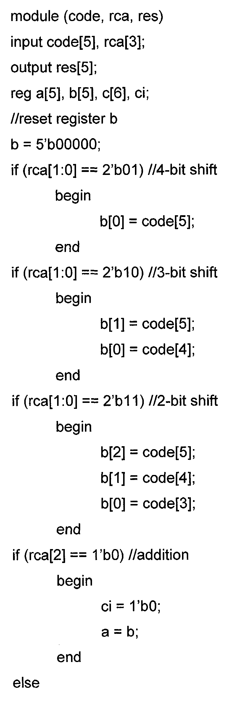 For those skilled in art the example shown above demonstrates how simple and fast color adjustment is performed in said preferred embodiment.
- Fig. 2 shows a related method to scale display data in a display driver circuit before it is written into a display RAM. The
first step 21 of said method is to define adjustment data for each primary color used by said display screen to adjust said colors according to the properties of said screen. The followingstep 22 is to store said adjustment data for each primary color in one or more registers providing one or more bits for each primary color.Step 23 describes the definition of a word structure to operate the unadjusted display data and to store the adjusted data in a display RAM wherein for each primary color a defined number of bits is assigned. Thenext step 24 shows the implementation of an algorithm to adjust each of the primary colors, used by said screen, in said display adjust circuit using a hardware description language. Now instep 25 the display data are downloaded from the system processor into the display adjust circuit, followed bystep 26 in which the display data, adjusted in the display adjust circuit according to the algorithm implemented earlier and according to the adjustment data defined and stored earlier, are written into the display RAM. In thelast step 27 the adjusted display data are forwarded from the display RAM to the display screen by the screen driver circuit.
Claims (31)
- A system to adjust colors in any kind of electronic display comprising:a color screen used as a display using primary colors of a color space;a system processor sending downloading display data to a display driver circuit; anda display driver circuit comprising:a processor interface logic providing the interface between said system processor and said display driver circuit;a display adjust circuit adjusting the display data received from said system processor via said processor interface logic and writing said modified display data into a display RAM;one or more color adjust registers;a display RAM for storing the adjusted display data, anda screen driver controlling said screen and sending said adjusted display data to said screen.
- The system of claim 1 wherein said color space is RGB or CMY.
- The system of claim 1 wherein said screen is a LCD display.
- The system of claim 3 wherein said LCD display is a CSTN display or a DSTN display.
- The system of claim 1 wherein said screen is a TFT display or an OLED display.
- The system of claim 1 wherein said display adjust circuit is using two color adjust registers to store the adjustment data defining the amount of adjustments.
- The system of claim 6 wherein said color adjustment registers are storing the adjustment data for each of all primary colors of the color space selected.
- The system of claim 7 wherein said color adjustment registers are comprising three bits to store the adjustment information for each of two primary colors and four bits for a third primary color.
- The system of claim 8 wherein said color adjustment registers are comprising three bits to store the adjustment information for each of red color and blue color and four bits for green color.
- The system of claim 1 wherein said display data are stored in said display RAM using a 16-bit word.
- The system of claim 10 wherein said 16-bit word comprises five bits each for two primary colors and six bits for a third primary color.
- The system of claim 11 wherein said 16-bit word comprises five bits for each red and blue 5 and 6 bits for green.
- The system of claim 1 wherein the color display data is linearly scaled by programmable amount.
- The system of claim 13 wherein the display data are adjusted for each color according equations which are implemented in said display adjust circuit using a hardware description language.
- The system of claim 14 wherein the display data are adjusted for each color according equations which are implemented in said display adjust circuit using register transfer level (RTL) language.
- The system of claim 13 wherein each primary color of the color display data is linearly scaled by programmable amount and wherein said programmable amount is defined in case of a required decrease of a primary color according to the equation
- The system of claim 13 wherein each primary color of the color display data is linearly scaled by programmable amount and wherein said programmable amount is defined in case of a required increase of a primary color according to the equation
- The system of claim 1 wherein said display driver circuit is implemented as an IC or as an ASIC.
- A method to adjust colors in any kind of electronic display comprising:providing a display screen, a system processor, and a display driver circuit comprising a processor interface logic, a display adjust circuit, one or more color adjust registers, a display RAM and a screen driver circuit;define adjustment data for each primary color used by said display screen to adjust said colors according to the properties of said screen;store said adjustment data for each primary color in one or more registers providing one or more bits for each primary color;define a word structure to operate the unadjusted display data and to store the adjusted display data in a display RAM wherein for each primary color a defined number of bits is assigned;implement an algorithm to adjust each of the primary colors, used by said screen, in said display adjust circuit using a hardware description language;download display data from system processor into display adjust circuit;adjust display data in display adjust circuit according to algorithm implemented earlier and according adjustment data defined and stored earlier and write adjusted display data into display RAM; andforward adjusted display data from the display RAM to the display screen by the screen driver circuit.
- The method of claim 19 wherein said primary colors belong to RGB color space or to CMY color space
- The method of claim 19 wherein said word structure comprises a 16-bit word.
- The method of claim 21 wherein said 16-bit word comprises five bits each for two primary colors and six bits for a third primary color.
- The method of claim 22 wherein said 16-bit word comprises five bits for each red and blue 5 and 6 bits for green.
- The method of claim 19 wherein said hardware description language is register transfer level (RTL) language.
- The method of claim 19 wherein said algorithm to decrease a primary color value is
- The method of claim 19 wherein said algorithm to increase a primary color value is
- The method of claim 19 wherein said color adjustment registers are comprising three bits to store the adjustment data for each of two primary colors and four bits for a third primary color.
- The method of claim 27 wherein said color adjustment registers are comprising three bits to store the adjustment data for each of blue and red and four bits for green.
- The method of claim 28 wherein said adjustment data for the color red are the following bit combinations:011 = +25% (2-bit shift and add),010 = +12.5% (3-bit shift and add),001 = +6.3% (4-bit shift and add),000 = no change (default value),101 = -6.3% (4-bit shift and subtract),110 = -12.5% (3-bit shift and subtract),111 = -25% (2-bit shift and subtract)
- The method of claim 28 wherein said adjustment parameters for the color blue are the following bit combinations:011 = +25% (2-bit shift and add),010 = +12.5% (3-bit shift and add),001 = +6.3% (4-bit shift and add),000 = no change (default value),101 = -6.3% (4-bit shift and subtract),110 = -12.5% (3-bit shift and subtract),111 = -25% (2-bit shift and subtract)
- The method of claim 27 wherein said adjustment parameters for the color green are the following bit combinations:0100 = +25% (2-bit shift and add)0011 = +12.5% (3-bit shift and add)0010 = +6.3% (4-bit shift and add)0001 = +3.1% (5-bit shift and add)0000 = no change (default value)1001 = -3.1% (5-bit shift and subtract)1010 = -6.3% (4-bit shift and subtract)1011 = -12.5% (3-bit shift and subtract)1100 = -25% (2-bit shift and subtract).
Priority Applications (6)
| Application Number | Priority Date | Filing Date | Title |
|---|---|---|---|
| EP03368087A EP1515300A1 (en) | 2003-09-09 | 2003-09-09 | Display color adjustment |
| US10/667,842 US7518581B2 (en) | 2003-09-09 | 2003-09-22 | Color adjustment of display screens |
| CNB2004100687068A CN100437743C (en) | 2003-09-09 | 2004-09-02 | Display color adjust |
| JP2004256714A JP2005084686A (en) | 2003-09-09 | 2004-09-03 | Display color adjustment |
| KR1020040071654A KR101042517B1 (en) | 2003-09-09 | 2004-09-08 | Display color adjustment |
| JP2011289778A JP2012118539A (en) | 2003-09-09 | 2011-12-28 | Display color adjustment |
Applications Claiming Priority (1)
| Application Number | Priority Date | Filing Date | Title |
|---|---|---|---|
| EP03368087A EP1515300A1 (en) | 2003-09-09 | 2003-09-09 | Display color adjustment |
Publications (1)
| Publication Number | Publication Date |
|---|---|
| EP1515300A1 true EP1515300A1 (en) | 2005-03-16 |
Family
ID=34130386
Family Applications (1)
| Application Number | Title | Priority Date | Filing Date |
|---|---|---|---|
| EP03368087A Withdrawn EP1515300A1 (en) | 2003-09-09 | 2003-09-09 | Display color adjustment |
Country Status (3)
| Country | Link |
|---|---|
| US (1) | US7518581B2 (en) |
| EP (1) | EP1515300A1 (en) |
| JP (1) | JP2012118539A (en) |
Families Citing this family (6)
| Publication number | Priority date | Publication date | Assignee | Title |
|---|---|---|---|---|
| KR100615676B1 (en) * | 2005-01-11 | 2006-08-25 | 삼성전자주식회사 | Content playback device and method for displaying WI screen |
| US8538625B1 (en) * | 2007-06-11 | 2013-09-17 | Phahol Lowchareonkul | Display system for use in a vehicle |
| CN103137097B (en) * | 2011-11-24 | 2015-04-01 | 宁波Gqy视讯股份有限公司 | Split joint screen red, green, blue (RGB) brightness adjusting method |
| CN107888758B (en) * | 2017-09-28 | 2020-06-16 | 努比亚技术有限公司 | Screen color adjusting method, mobile terminal and computer readable storage medium |
| CN113345386B (en) * | 2020-03-02 | 2022-10-04 | 苏州佳世达电通有限公司 | Display device and color adjustment method |
| US12499513B2 (en) * | 2023-08-11 | 2025-12-16 | Rockwell Collins, Inc. | EFVS integrated interface for image display control |
Citations (4)
| Publication number | Priority date | Publication date | Assignee | Title |
|---|---|---|---|---|
| US5774112A (en) * | 1994-10-25 | 1998-06-30 | International Business Machines Corporation | Method and apparatus for tone correction of a digital color image with preservation of the chromaticity of the image |
| US20010003543A1 (en) * | 1999-12-09 | 2001-06-14 | Shuichi Kagawa | Image display device |
| EP1227468A2 (en) * | 2001-01-30 | 2002-07-31 | Eastman Kodak Company | Method of integrating digital control and display devices on a common substrate |
| EP1265219A1 (en) * | 2000-08-28 | 2002-12-11 | Seiko Epson Corporation | Environment adaptive image display system, image processing method and information storing medium |
Family Cites Families (16)
| Publication number | Priority date | Publication date | Assignee | Title |
|---|---|---|---|---|
| DE2844158C3 (en) * | 1978-10-10 | 1981-10-15 | Burda Verwaltungs Kg Schutterwald, 7600 Offenburg | Process for the reproduction of original documents which are scanned for their color content according to a three-range process |
| EP0151846B1 (en) * | 1984-02-15 | 1987-10-14 | International Business Machines Corporation | Colour display apparatus and method of coding a colour image |
| JP2876853B2 (en) * | 1991-10-24 | 1999-03-31 | 松下電器産業株式会社 | Color converter |
| DE4418782C2 (en) * | 1993-05-21 | 1997-01-09 | Mitsubishi Electric Corp | System and method for adjusting a color image |
| US5488390A (en) * | 1993-07-29 | 1996-01-30 | Cirrus Logic, Inc. | Apparatus, systems and methods for displaying a cursor on a display screen |
| US5608548A (en) * | 1994-12-23 | 1997-03-04 | Hewlett-Packard Company | Automatic color adjustment in a document processing environment |
| US6388648B1 (en) * | 1996-11-05 | 2002-05-14 | Clarity Visual Systems, Inc. | Color gamut and luminance matching techniques for image display systems |
| US6199031B1 (en) * | 1998-08-31 | 2001-03-06 | Vlsi Technology, Inc. | HDL simulation interface for testing and verifying an ASIC model |
| JP3399853B2 (en) * | 1998-09-30 | 2003-04-21 | 三菱電機株式会社 | Display panel display control circuit |
| JP3565328B2 (en) * | 2000-06-13 | 2004-09-15 | シャープ株式会社 | Display device and defective dot compensation method thereof |
| JP2001060082A (en) * | 1999-08-24 | 2001-03-06 | Matsushita Electric Ind Co Ltd | Color reproduction terminal device and network color reproduction system |
| US6801213B2 (en) * | 2000-04-14 | 2004-10-05 | Brillian Corporation | System and method for superframe dithering in a liquid crystal display |
| JP3971892B2 (en) * | 2000-09-08 | 2007-09-05 | 株式会社日立製作所 | Liquid crystal display |
| KR100421500B1 (en) * | 2001-06-09 | 2004-03-12 | 엘지.필립스 엘시디 주식회사 | Method and Apparatus For Corecting Color Liquid Crystal Display |
| KR100859514B1 (en) * | 2002-05-30 | 2008-09-22 | 삼성전자주식회사 | Liquid crystal display and its driving device |
| TW563377B (en) * | 2002-06-25 | 2003-11-21 | Weltrend Semiconductor Inc | Independent adjusting method of individual color of display screen |
-
2003
- 2003-09-09 EP EP03368087A patent/EP1515300A1/en not_active Withdrawn
- 2003-09-22 US US10/667,842 patent/US7518581B2/en active Active
-
2011
- 2011-12-28 JP JP2011289778A patent/JP2012118539A/en active Pending
Patent Citations (4)
| Publication number | Priority date | Publication date | Assignee | Title |
|---|---|---|---|---|
| US5774112A (en) * | 1994-10-25 | 1998-06-30 | International Business Machines Corporation | Method and apparatus for tone correction of a digital color image with preservation of the chromaticity of the image |
| US20010003543A1 (en) * | 1999-12-09 | 2001-06-14 | Shuichi Kagawa | Image display device |
| EP1265219A1 (en) * | 2000-08-28 | 2002-12-11 | Seiko Epson Corporation | Environment adaptive image display system, image processing method and information storing medium |
| EP1227468A2 (en) * | 2001-01-30 | 2002-07-31 | Eastman Kodak Company | Method of integrating digital control and display devices on a common substrate |
Also Published As
| Publication number | Publication date |
|---|---|
| US20050052476A1 (en) | 2005-03-10 |
| US7518581B2 (en) | 2009-04-14 |
| JP2012118539A (en) | 2012-06-21 |
Similar Documents
| Publication | Publication Date | Title |
|---|---|---|
| US20230282153A1 (en) | Methods and systems for non-linear compensation in display applications | |
| US7619637B2 (en) | Systems and methods for improved gamut mapping from one image data set to another | |
| US9997135B2 (en) | Method for producing a color image and imaging device employing same | |
| JP4705917B2 (en) | Method and apparatus for converting from a source color space to a target color space | |
| KR100607144B1 (en) | Liquid crystal display device | |
| US7808462B2 (en) | Display apparatus | |
| JP6351034B2 (en) | Display device, display panel driver, image processing device, and display panel driving method | |
| US9251761B2 (en) | Gray-scale correction method for display device, and method of producing display device | |
| CN105280146B (en) | Control signal generating circuit, video display devices and control signal creating method | |
| JP4363720B2 (en) | A device for creating color palettes | |
| KR101788681B1 (en) | Color correction to compensate for displays' luminance and chrominance transfer characteristics | |
| JP2001083940A (en) | Color image processing method, color image processing device, liquid crystal display device | |
| WO2006108083A2 (en) | Systems and methods for implementing low cost gamut mapping algorithms | |
| US8111301B2 (en) | Method of performing auto white balance in YCbCr color space | |
| US20080007565A1 (en) | Color correction circuit, driving device, and display device | |
| US7663678B2 (en) | Gamma correction, image processing method and program, gamma correction circuit, image processing apparatus, and display apparatus | |
| JP2001042833A (en) | Color display | |
| US20060055835A1 (en) | Image processing apparatus and image processing method | |
| JP2008026339A (en) | Display device | |
| JP2012118539A (en) | Display color adjustment | |
| JP6815099B2 (en) | Color adjustment circuit, display driver and display device | |
| KR101042517B1 (en) | Display color adjustment | |
| JP2006258850A (en) | Gamma correction circuit | |
| CN113920927B (en) | Display method, display panel and electronic equipment | |
| CN100472602C (en) | Gamma correction method and circuit, image processing device and display device |
Legal Events
| Date | Code | Title | Description |
|---|---|---|---|
| PUAI | Public reference made under article 153(3) epc to a published international application that has entered the european phase |
Free format text: ORIGINAL CODE: 0009012 |
|
| AK | Designated contracting states |
Kind code of ref document: A1 Designated state(s): AT BE BG CH CY CZ DE DK EE ES FI FR GB GR HU IE IT LI LU MC NL PT RO SE SI SK TR |
|
| AX | Request for extension of the european patent |
Extension state: AL LT LV MK |
|
| 17P | Request for examination filed |
Effective date: 20050916 |
|
| AKX | Designation fees paid |
Designated state(s): AT BE BG CH CY CZ DE DK EE ES FI FR GB GR HU IE IT LI LU MC NL PT RO SE SI SK TR |
|
| STAA | Information on the status of an ep patent application or granted ep patent |
Free format text: STATUS: THE APPLICATION IS DEEMED TO BE WITHDRAWN |
|
| 18D | Application deemed to be withdrawn |
Effective date: 20070331 |