EP1515042A2 - Valving for multi-stage vacuum pumps - Google Patents
Valving for multi-stage vacuum pumps Download PDFInfo
- Publication number
- EP1515042A2 EP1515042A2 EP04255438A EP04255438A EP1515042A2 EP 1515042 A2 EP1515042 A2 EP 1515042A2 EP 04255438 A EP04255438 A EP 04255438A EP 04255438 A EP04255438 A EP 04255438A EP 1515042 A2 EP1515042 A2 EP 1515042A2
- Authority
- EP
- European Patent Office
- Prior art keywords
- stage
- pumping chamber
- pump according
- piston
- spool valve
- Prior art date
- Legal status (The legal status is an assumption and is not a legal conclusion. Google has not performed a legal analysis and makes no representation as to the accuracy of the status listed.)
- Withdrawn
Links
Images

Classifications
-
- F—MECHANICAL ENGINEERING; LIGHTING; HEATING; WEAPONS; BLASTING
- F04—POSITIVE - DISPLACEMENT MACHINES FOR LIQUIDS; PUMPS FOR LIQUIDS OR ELASTIC FLUIDS
- F04B—POSITIVE-DISPLACEMENT MACHINES FOR LIQUIDS; PUMPS
- F04B37/00—Pumps having pertinent characteristics not provided for in, or of interest apart from, groups F04B25/00 - F04B35/00
- F04B37/10—Pumps having pertinent characteristics not provided for in, or of interest apart from, groups F04B25/00 - F04B35/00 for special use
- F04B37/14—Pumps having pertinent characteristics not provided for in, or of interest apart from, groups F04B25/00 - F04B35/00 for special use to obtain high vacuum
-
- F—MECHANICAL ENGINEERING; LIGHTING; HEATING; WEAPONS; BLASTING
- F04—POSITIVE - DISPLACEMENT MACHINES FOR LIQUIDS; PUMPS FOR LIQUIDS OR ELASTIC FLUIDS
- F04B—POSITIVE-DISPLACEMENT MACHINES FOR LIQUIDS; PUMPS
- F04B25/00—Multi-stage pumps
- F04B25/02—Multi-stage pumps of stepped piston type
-
- F—MECHANICAL ENGINEERING; LIGHTING; HEATING; WEAPONS; BLASTING
- F04—POSITIVE - DISPLACEMENT MACHINES FOR LIQUIDS; PUMPS FOR LIQUIDS OR ELASTIC FLUIDS
- F04B—POSITIVE-DISPLACEMENT MACHINES FOR LIQUIDS; PUMPS
- F04B39/00—Component parts, details, or accessories, of pumps or pumping systems specially adapted for elastic fluids, not otherwise provided for in, or of interest apart from, groups F04B25/00 - F04B37/00
- F04B39/08—Actuation of distribution members
Definitions
- the invention relates to valving for multi-stage vacuum pumps and particularly, but not exclusively, to valving for multi-stage dry vacuum pumps.
- Piston pumps are ideal for dry vacuum pumps as they are relatively easy to seal with contacting PTFE seals.
- the stages in these pumps are typically valved with reed valves or similar non-return valves. This limits the performance of such pumps to a few mbar as lower pressure forces are insufficient to actuate the reeds.
- Some pumps have used a striker to physically knock the reed valve open.
- An alternative approach has been to have ports in the cylinder walls that are opened and closed as the cylinder reciprocates. However, none of these approaches is ideal.
- a multi-stage reciprocating piston vacuum pump having at least a first stage, a second stage and a third stage, the pump comprising spool valve means arranged to control flow of a pumped fluid from the first stage to the second stage, and from the second stage to the third stage.
- a multi-stage reciprocating piston vacuum pump having at least a first stage, a second stage and a third stage, the pump comprising spool valve means arranged to control flow of a pumped fluid from the first stage to the second stage, and wherein flow from the second stage to the third stage is controlled by pressure actuated valve means actuated by the pressure of the pumped fluid.
- a multi-stage vacuum pump comprising a first piston in a first cylinder defining a first stage pumping chamber, a second piston in a second cylinder defining a second stage pumping chamber and a spool valve for controlling flow from the first stage pumping chamber to the second stage pumping chamber, wherein either the first cylinder and the first piston, or the second cylinder and the second piston, are stepped so as to define a third stage pumping chamber, the spool valve being arranged to control flow from the second stage pumping chamber to the third stage pumping chamber.
- a multi-stage vacuum pump comprising a first piston in a first cylinder defining a first stage pumping chamber, a second piston in a second cylinder defining a second stage pumping chamber, a spool valve for controlling flow from the first stage pumping chamber to the second stage pumping chamber, a third stage pumping chamber downstream of the second stage pumping chamber, wherein flow between the second stage pumping chamber and the third stage pumping chamber is controlled by a pressure actuated valve actuated by the pressure of the pumped fluid.
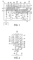
- a four-stage dry vacuum pump 10 comprises a casing 12 that houses a cylinder block 13.
- the cylinder block 13 defines two side-by-side stepped cylinder bores 14, 16.
- Respective stepped pistons 18, 20 are housed in the cylinder bores 14, 16 and are connected by respective connecting rods 22 to a crankshaft 24.
- the crankshaft 24 is driven by an electric motor 26, which may be housed within the casing 12 or bolted to the exterior thereof as is conventional in the art.
- the casing has an inlet port 28 and an exhaust port 30.
- the exhaust port 30 is closed by a non-return valve 32, which may be of any suitable design, such as a conventional reed valve.
- the pump may be provided with any suitable connection devices to permit the inlet and outlet ports 28, 30 to be connected to apparatus upstream and downstream of the pump as is required for the use to which the pump is intended.
- the cylinder bores 14, 16 and pistons 18, 20 are stepped so as to define four pumping chambers 34, 36, 38, 40 that are valved in such a way as to provide four pumping stages.
- the cylinder bore 14 includes an upper cylinder portion defined by a top wall 42 of the cylinder block 13 and an upper cylindrical side wall 44 that extends downwardly from the top wall and a lower cylinder portion defined by a lower cylindrical side wall 46 and a lateral wall 48 that extends perpendicular to the side walls 44, 46 and interconnects the lower end of the side wall 44 and the upper end of the side wall 46.
- the piston 18 has an upper portion 50 sized to be slideably received in the upper cylinder portion and a larger diameter lower portion 52 sized to be a sliding fit in the lower cylinder portion.
- Respective seals are provided between the upper piston portion 50 of the piston and the upper cylinder side wall 44 and the lower piston portion 52 and the lower side wall 46. These seals may be of any suitable conventional design and may, for example, be PTFE seals.
- the cylinder bore 16 includes an upper cylinder portion defined by a top wall 56 of the cylinder block 13 and an upper cylindrical side wall 58 that extends downwardly from the top wall and a lower cylinder portion defined by a lower cylindrical side wall 60 and a lateral wall 62 that extends perpendicular to the side walls 58, 60 and interconnects the lower end of the side wall 58 and upper end of the side wall 60.
- the piston 20 has an upper portion 64 sized to be slideably received in the upper cylinder portion and a larger diameter lower portion 66 sized to be a sliding fit in the lower cylinder portion.
- Respective seals are provided between the upper portion 64 of the piston 20 and the upper cylindrical sidewall 58 and the lower piston portion 66 and the lower side wall 60. In the same way as with the cylinder bore 14 and piston 18, these seals may be of any suitable conventional design and may, for example, be PTFE seals.
- the pumping chamber 34 is defined between the crown 68 of the piston 18 and the top wall 42 and upper cylindrical side wall 44 of the upper cylinder portion of the cylinder bore 14.
- a side entry port 70 defined in the upper cylindrical side wall 44 connects the pumping chamber 34 with a valve bore 72 extending between and parallel to the cylinder bores 14, 16.
- the upper end of the valve bore 72 defines the pump inlet port 28.
- the pumping chamber 36 is defined between the crown 74 of the piston 20 and the top wall 56 and upper cylindrical wall 58 of the cylinder bore 16.
- a side entry port 76 defined in the upper cylindrical wall 58 adjacent the top wall 56 connects the pumping chamber 36 with the valve bore 72.
- the pumping chamber 38 is defined between an upwardly facing annular wall 77 of the lower piston portion 52, the lateral wall 48, the lower cylindrical wall 46 and the circumferentially extending sidewall of the upper piston portion 50.
- a side entry port 78 defined in the lower cylindrical side wall 46 adjacent the lateral wall 48 connects the pumping chamber 38 with the valve bore 72.
- the pumping chamber 40 is defined between an upwardly facing annular wall 80 of the lower piston portion 66 of the piston 20, the lateral wall 62, the lower cylindrical side wall 60 of the cylinder bore 16 and the circumferentially extending sidewall of the upper piston portion 64.
- a side entry port 82 defined in the lower cylindrical side wall 60 connects the pumping chamber 40 with the valve bore 72.
- the valve bore 72 houses a spool 88 comprising a valve rod 90 and three disc-like islands 92, 94, 96.
- the valve rod 90 extends axially in the valve bore 72 and is connected by a connecting rod 98 to the crankshaft 24.
- the islands 92, 94, 96 are sized so as to be a close sliding fit in the valve bore 72 and are spaced apart along the length of the valve rod.
- the spool 88 is connected with the crankshaft 24 in such a way that it reciprocates 90° out of phase with the two pistons 18, 20 and this, in combination with the arrangement of the side entry ports 70, 76, 78, 82 and islands 92, 94, 96, ensures that the gas received at the pump inlet 28 passes sequentially from the pumping chamber 34 (first stage) to the pumping chamber 36 (second stage), from the pumping chamber 36 to the pumping chamber 38 (third stage), and from the pumping chamber 38 to the pumping chamber 40 (fourth stage), thus providing a four-stage pumping process.
- the pumped gas in the final stage pumping chamber 40 is released through the exhaust port 30 via the non-return valve 32.
- the spool 88 is positively driven by the crank shaft 24 and is therefore less susceptible to sticking and leakage than conventional interstage valving that is actuated by the gas pressure. Providing a positive drive also means that the pump can operate at lower pressures since gas pressure is not required to actuate the valve. Furthermore, valve losses between the stages can be minimised, since it can be ensured that the valve ports are fully opened and the timing of the valve opening can be optimised.
- pistons and cylinders could comprise more than one step so as to provide three or more pumping stages per cylinder/piston combination.
- a stepped piston could be provided next to a non-stepped piston to provide a three stage pump.
- first and second stage pumping chambers 34, 36 disposed above the third and fourth stage pumping chambers 38, 40 provides the advantage that their seals are isolated from atmospheric pressure by the seals of the third and fourth stage pumping chambers. This reduces the likelihood of leakage and improves pump efficiency.
- spool 88 is shown being driven from the crankshaft 24 via a direct connection in the form of connecting rod 98
- alternative driving means for the spool could be provided.
- the spool valve could be driven against a biasing spring arrangement by a cam actuated by a take-off drive from the crankshaft.
- Another alternative would be to use a scotch yolk mechanism. This provides certain advantages over a simple connecting rod or a cam mechanism. Specifically, a scotch yolk mechanism provides a true simple harmonic action, reduced out of balance forces and negligible radial force, and should increase the life of the spool seals.
- an arrangement as shown in the drawings is simple and efficient and for that reason is presently preferred.
- the exhaust port 30 is closed by a conventional reed valve. It will be understood that as an alternative, an exhaust port arrangement may be provided that permits the exhaust to be controlled by the spool 88.
- the design embodied in the pump 10 provides the possibility of a low cost 2m 3 /hr pump capable of backing small turbo pumps, although it is not limited to such use. It offers an improved and more reliable alternative to the diaphragm pump, which at present is the standard pump used for backing turbo pumps.
- a range of pumps based on pump 10 having capacities between 0.5 and 5m 3 /hr is presently contemplated.
Landscapes
- Engineering & Computer Science (AREA)
- Mechanical Engineering (AREA)
- General Engineering & Computer Science (AREA)
- Compressors, Vaccum Pumps And Other Relevant Systems (AREA)
- Applications Or Details Of Rotary Compressors (AREA)
Abstract
Description
Claims (23)
- A multi-stage reciprocating piston vacuum pump having at least a first stage, a second stage and a third stage, the pump comprising spool valve means arranged to control flow of a pumped fluid from the first stage to the second stage, and from the second stage to the third stage.
- A pump according to Claim 1, wherein the first stage comprises a first stage pumping chamber defined by a first piston in a first cylinder, and the second stage comprises a second stage pumping chamber defined by a second piston in a second cylinder, the spool valve means being arranged to control flow of a pumped fluid from the first stage pumping chamber to the second stage pumping chamber.
- A pump according to Claim 2, wherein one of the first and second cylinders and the piston therein are stepped so as to define a third stage pumping chamber of the third stage, the spool valve being arranged to control flow from the second stage pumping chamber to the third stage pumping chamber.
- A pump according to Claim 2, wherein the first and second cylinders and the pistons therein are each stepped so as to define a third stage pumping chamber of the third stage and a fourth stage pumping chamber of a fourth stage, the spool valve being arranged to control flow sequentially from the first stage pumping chamber to the fourth stage pumping chamber.
- A pump according to Claim 4, wherein the first piston and first cylinder define the third stage pumping chamber and the second piston and second cylinder define the fourth stage pumping chamber.
- A pump according to Claim 5, wherein the first stage pumping chamber is disposed between a top wall of the first cylinder and a crown of the first piston and the second stage pumping chamber is disposed between a top wall of the second cylinder and a crown of the second piston such that the third stage pumping chamber is disposed below the first stage pumping chamber and the fourth stage pumping chamber is disposed below the second stage pumping chamber.
- A pump according to any of Claims 2 to 6, wherein the spool valve is disposed between the first and second cylinders.
- A pump according to Claim 7, wherein the spool valve comprises a passage extending between the first and second cylinders in a lengthways direction thereof and a rod carrying a plurality of islands arranged to reciprocate in the passage, each pumping chamber having a port leading to the passage.
- A pump according to Claim 8, wherein the first and second cylinders and the passage are axially parallel.
- A pump according to Claim 8 or 9, wherein the first and second pistons are driven from a crankshaft and the spool valve rod is connected with the crankshaft so as to be driven by it.
- A pump according to Claim 8, 9 or 10, wherein the spool valve rod reciprocates out of phase with the first and second pistons.
- A pump according to any of the preceding claims, wherein the spool valve defines an exhaust port of the pump and controls flow through the exhaust port.
- A multi-stage reciprocating piston vacuum pump having at least a first stage, a second stage and a third stage, the pump comprising spool valve means arranged to control flow of a pumped fluid from the first stage to the second stage, and wherein flow from the second stage to the third stage is controlled by pressure actuated valve means actuated by the pressure of the pumped fluid.
- A pump according to Claim 13, wherein the pressure actuated valve is a reed or flap valve.
- A pump according to Claim 13 or 14, wherein the first stage comprises a first stage pumping chamber defined by a first piston in a first cylinder, the second stage comprises a second stage pumping chamber defined by a second piston in a second cylinder.
- A pump according to Claim 15, wherein either the first cylinder and the first piston or the second cylinder and the second piston are stepped so as to define a third stage pumping chamber of the third stage and wherein the flow between the second stage pumping chamber and the third stage pumping chamber is controlled by the pressure actuated valve.
- A pump according to Claim 16, comprising a fourth stage pumping chamber downstream of the second stage pumping chamber, wherein flow between the third stage pumping chamber and the fourth stage pumping chamber is controlled by a further pressure actuated valve.
- A pump according to any of Claims 15 to 17, wherein the spool valve is disposed between the first and second cylinders.
- A pump according to Claim 18, wherein the spool valve comprises a passage extending between the first and second cylinders in a lengthways direction thereof and a rod carrying a plurality of islands arranged to reciprocate in the passage, each pumping chamber having a port leading to the passage.
- A pump according to Claim 19, wherein the first and second cylinders and the passage are axially parallel.
- A pump according to Claim 19 or 20, wherein the first and second pistons are driven from a crankshaft and the spool valve rod is connected with the crankshaft so as to be driven by it.
- A pump according to Claim 19, 20 or 21, wherein the spool valve rod reciprocates out of phase with the first and second pistons.
- A pump according to any of Claims 13 to 22, wherein the spool valve defines an exhaust port of the pump and controls flow through the exhaust port.
Applications Claiming Priority (2)
| Application Number | Priority Date | Filing Date | Title |
|---|---|---|---|
| GB0321576 | 2003-09-15 | ||
| GBGB0321576.1A GB0321576D0 (en) | 2003-09-15 | 2003-09-15 | Valving for multi-stage vacuum pumps |
Publications (2)
| Publication Number | Publication Date |
|---|---|
| EP1515042A2 true EP1515042A2 (en) | 2005-03-16 |
| EP1515042A3 EP1515042A3 (en) | 2005-09-28 |
Family
ID=29227109
Family Applications (1)
| Application Number | Title | Priority Date | Filing Date |
|---|---|---|---|
| EP04255438A Withdrawn EP1515042A3 (en) | 2003-09-15 | 2004-09-08 | Valving for multi-stage vacuum pumps |
Country Status (3)
| Country | Link |
|---|---|
| US (1) | US7318706B2 (en) |
| EP (1) | EP1515042A3 (en) |
| GB (1) | GB0321576D0 (en) |
Cited By (1)
| Publication number | Priority date | Publication date | Assignee | Title |
|---|---|---|---|---|
| ITMI20112392A1 (en) * | 2011-12-27 | 2013-06-28 | Nuovo Pignone Spa | EQUIPMENT AND METHODS FOR IMPLEMENTING VALVES |
Families Citing this family (1)
| Publication number | Priority date | Publication date | Assignee | Title |
|---|---|---|---|---|
| NO20220232A1 (en) * | 2022-02-22 | 2023-08-23 | Heaten As | Improved compressor |
Family Cites Families (13)
| Publication number | Priority date | Publication date | Assignee | Title |
|---|---|---|---|---|
| US772266A (en) * | 1904-01-27 | 1904-10-11 | Stephen Evans Alley | Air-compressor. |
| US1057135A (en) * | 1911-01-17 | 1913-03-25 | William S Fairhurst | Air-compressor. |
| US3098480A (en) * | 1960-11-29 | 1963-07-23 | William D Worthington | System for fluid transfusion |
| US3386384A (en) * | 1966-06-27 | 1968-06-04 | Cicero C Brown | Multiple power consuming devices |
| DE2161560A1 (en) | 1971-12-11 | 1973-06-14 | Langen & Co | PISTON PUMP |
| US3791780A (en) * | 1972-05-11 | 1974-02-12 | Robinair Mfg Corp | Vacuum pump |
| US4102608A (en) * | 1975-12-24 | 1978-07-25 | Commonwealth Scientific And Industrial Research Organization | Reciprocatory piston and cylinder machines |
| US4370103A (en) * | 1980-04-28 | 1983-01-25 | Arrowhead Research | Piston pump with discharge valve, inlet valve and misalignment compensating means in a pump head |
| AU564301B2 (en) * | 1981-08-13 | 1987-08-06 | Commonwealth Scientific And Industrial Research Organisation | Reciprocatory piston and cylinder machine |
| GB2162590B (en) | 1984-07-10 | 1988-02-10 | Dale | Hydraulically driven pumps |
| US4784579A (en) | 1986-12-19 | 1988-11-15 | Allied-Signal Inc. | Hydraulic-pneumatic power transfer unit |
| JPH02102385A (en) * | 1988-10-08 | 1990-04-13 | Toyo Eng Corp | exhaust system |
| US5540562A (en) * | 1994-04-28 | 1996-07-30 | Ashirus Technologies, Inc. | Single-piston, multi-mode fluid displacement pump |
-
2003
- 2003-09-15 GB GBGB0321576.1A patent/GB0321576D0/en not_active Ceased
-
2004
- 2004-08-18 US US10/920,674 patent/US7318706B2/en not_active Expired - Fee Related
- 2004-09-08 EP EP04255438A patent/EP1515042A3/en not_active Withdrawn
Cited By (3)
| Publication number | Priority date | Publication date | Assignee | Title |
|---|---|---|---|---|
| ITMI20112392A1 (en) * | 2011-12-27 | 2013-06-28 | Nuovo Pignone Spa | EQUIPMENT AND METHODS FOR IMPLEMENTING VALVES |
| WO2013098104A1 (en) * | 2011-12-27 | 2013-07-04 | Nuovo Pignone S.P.A | Apparatuses and methods for actuating valves |
| CN104011380A (en) * | 2011-12-27 | 2014-08-27 | 诺沃皮尼奥内有限公司 | Apparatus and method for actuating a valve |
Also Published As
| Publication number | Publication date |
|---|---|
| US20050058552A1 (en) | 2005-03-17 |
| US7318706B2 (en) | 2008-01-15 |
| EP1515042A3 (en) | 2005-09-28 |
| GB0321576D0 (en) | 2003-10-15 |
Similar Documents
| Publication | Publication Date | Title |
|---|---|---|
| EP0280264B1 (en) | Multi-stage vacuum pump | |
| KR101476494B1 (en) | Fluid Working Machines and Methods | |
| US20110116957A2 (en) | Reciprocating pump | |
| US7399168B1 (en) | Air driven diaphragm pump | |
| EP1750514B1 (en) | Double-acting, high-pressure cryogenic pump | |
| US20090047159A1 (en) | Multi-stage gas compressing apparatus | |
| EP0623749B1 (en) | Rotary gas compressor | |
| US7318706B2 (en) | Valving for multi-stage vacuum pumps | |
| US7670119B2 (en) | Multistage vacuum pump and a pumping installation including such a pump | |
| US20070116588A1 (en) | Piston compressor for compressing gaseous media in at least two working chambers | |
| US7226276B2 (en) | Multi-stage reciprocating vacuum pump and method of operating the same | |
| WO2014152982A1 (en) | Internal combustion engine | |
| US20250146483A1 (en) | Reciprocating compressor with non-self-actuated suction valve | |
| US9957958B2 (en) | Reciprocating integral linear engine compressor | |
| JP2003139056A (en) | Evacuation device | |
| RU2618362C2 (en) | Bellows pump | |
| US744547A (en) | Pumping-engine. | |
| US12421852B1 (en) | Three-cycle (stroke) rotary radial vane piston internal combustion engine | |
| KR20120102904A (en) | Gas compressor | |
| WO2013171453A1 (en) | Diaphragm pump | |
| US20250180001A1 (en) | Compressor with suction valves in piston and crankcase | |
| AU2026203427A1 (en) | Reciprocating compressor with non-self-actuated suction valve | |
| SU1451349A1 (en) | Two-stage vacuum pump | |
| SU1618906A1 (en) | High-vacuum unit | |
| CN117108476A (en) | Variable-frequency gas compressor |
Legal Events
| Date | Code | Title | Description |
|---|---|---|---|
| PUAI | Public reference made under article 153(3) epc to a published international application that has entered the european phase |
Free format text: ORIGINAL CODE: 0009012 |
|
| AK | Designated contracting states |
Kind code of ref document: A2 Designated state(s): AT BE BG CH CY CZ DE DK EE ES FI FR GB GR HU IE IT LI LU MC NL PL PT RO SE SI SK TR |
|
| AX | Request for extension of the european patent |
Extension state: AL HR LT LV MK |
|
| PUAL | Search report despatched |
Free format text: ORIGINAL CODE: 0009013 |
|
| AK | Designated contracting states |
Kind code of ref document: A3 Designated state(s): AT BE BG CH CY CZ DE DK EE ES FI FR GB GR HU IE IT LI LU MC NL PL PT RO SE SI SK TR |
|
| AX | Request for extension of the european patent |
Extension state: AL HR LT LV MK |
|
| RIC1 | Information provided on ipc code assigned before grant |
Ipc: 7F 04D 17/16 B Ipc: 7F 04D 19/04 B Ipc: 7F 04B 25/02 B Ipc: 7F 04B 53/12 B Ipc: 7F 04B 37/14 A |
|
| AKX | Designation fees paid | ||
| REG | Reference to a national code |
Ref country code: DE Ref legal event code: 8566 |
|
| STAA | Information on the status of an ep patent application or granted ep patent |
Free format text: STATUS: THE APPLICATION IS DEEMED TO BE WITHDRAWN |
|
| 18D | Application deemed to be withdrawn |
Effective date: 20060329 |