EP1514778A1 - Système de butée pour le positionnement latéral relatif d'éléments de carrosserie automobile - Google Patents
Système de butée pour le positionnement latéral relatif d'éléments de carrosserie automobile Download PDFInfo
- Publication number
- EP1514778A1 EP1514778A1 EP04300552A EP04300552A EP1514778A1 EP 1514778 A1 EP1514778 A1 EP 1514778A1 EP 04300552 A EP04300552 A EP 04300552A EP 04300552 A EP04300552 A EP 04300552A EP 1514778 A1 EP1514778 A1 EP 1514778A1
- Authority
- EP
- European Patent Office
- Prior art keywords
- reinforcement
- stop
- abutment
- bodywork
- elements
- Prior art date
- Legal status (The legal status is an assumption and is not a legal conclusion. Google has not performed a legal analysis and makes no representation as to the accuracy of the status listed.)
- Granted
Links
- 230000002787 reinforcement Effects 0.000 claims abstract description 37
- 238000005520 cutting process Methods 0.000 description 3
- 238000000034 method Methods 0.000 description 3
- 210000000452 mid-foot Anatomy 0.000 description 2
- 230000004075 alteration Effects 0.000 description 1
- 230000000694 effects Effects 0.000 description 1
- 239000011521 glass Substances 0.000 description 1
- 230000001771 impaired effect Effects 0.000 description 1
- 238000005304 joining Methods 0.000 description 1
- 238000004519 manufacturing process Methods 0.000 description 1
- 238000010008 shearing Methods 0.000 description 1
Images
Classifications
-
- B—PERFORMING OPERATIONS; TRANSPORTING
- B62—LAND VEHICLES FOR TRAVELLING OTHERWISE THAN ON RAILS
- B62D—MOTOR VEHICLES; TRAILERS
- B62D25/00—Superstructure or monocoque structure sub-units; Parts or details thereof not otherwise provided for
- B62D25/06—Fixed roofs
Definitions
- the invention relates to the field of elements structural or bodywork of a motor vehicle, and more particularly the relative positioning of components of the bodywork between them, such as that the body side, the body lining and the reinforcement placed between these two, at the level of the junction of the roof and a door jamb.
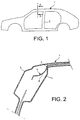
- the invention is reports in particular, but not necessarily, to the junction of the roof 1 and the body side, at the passenger compartment, preferably in front and the rear of the amount 2 separating the two doors side.
- the mixed line, in bold, cutting the roof 1 at this level makes it possible to locate an A-A section necessary to define Figure 2.
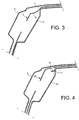
- the latter is a cut according to the line A-A of Figure 1 and allows to visualize three main elements constituting the bodywork at this level, namely a body side 3, placed at outside, a cashier liner 4 placed at inside, and a box reinforcement 5 placed between the two.
- An abutment 6 is provided for allow the positioning of the reinforcement 5, according to the axis cross-section of the vehicle, compared to the liner of 4.
- This stop 6 is generally constituted of a stamped part of curved shape.
- the base 7 of this stop 6, joining with the part of the reinforcement 5 at roof level 1 therefore has a surface acting as a stop to position the reinforcement 5 with respect to the body liner 4, as shown in Figure 3.
- the base 7 of the abutment 6 consisting of a rounded part has a disadvantage concerning the accuracy of the lateral positioning of the reinforcement 5 on the lining of 4. Indeed, depending on the height of positioning the reinforcement 5 with respect to the lining 4, the relative lateral position of these two items may vary. Moreover, if the depth stamping, during the manufacture of the stop 6 is not big enough, the base 7 of the latter is not will not be positioned on the reinforcement 5 at the right place. As a result, the reinforcement 5 will not be positioned laterally correctly in relation to the 4. The stamped part constituting the stop 6 therefore needs a sufficient depth large and therefore of a length also great. This alters the mechanical characteristics of the reinforcement 5 level of the stop 6, which is positioned on the edge reinforcement.
- the object of the invention is to remedy disadvantages mentioned above by presenting a type different lateral positioning stop of these different body parts relative to each other to others.
- the main object of the invention is a stop system for lateral positioning relating to automobile bodywork, preferably at the junction of the roof and the frame of doors, between a bodywork reinforcement and another body part, the system comprising at least a point deformation of a first element intended to come into contact with a second element, the reinforcement of bodywork constituting one of these two elements.
- the partial deformation consists of a double puncture formed by two slits longitudinal parallels, between which the part cut is deformed so as to be inside the cockpit when the first element on which it is formed is put in place.
- the first element is the reinforcement used between the body liner and the body side, the second element being the body lining.
- a preferred embodiment of the first implementation provides that the cash side possesses also a stop for its relative positioning to the assembly consisting of the reinforcement and the lining of crate, this stop being also obtained by a double flat deformation formed by two slits longitudinal parallels between which the part cut is deformed towards the interior of the passenger compartment, when the cash side is set up on the assembly constituted by the reinforcement and the lining of checkout.
- the first element is the crate side bearing the stop, the second being the box reinforcement placed between the crate side and the crate liner.
- the stopper 10 is arranged according to the invention with respect to the stop 6 of FIG. effect, the reinforcement 15 placed between the body side 3 and the body liner 4 has been partially stamped with shearing, or other equivalent process, that is to say a double parallel cutting according to two slots, so that one party having two parallel sides either swept inward from the cockpit once the reinforcement is put in place, with a shear on both sides of the stamp.
- the abutment 10 is therefore a stamping double burst.
- the inner side 11 of the abutment 10 is in contact with the outer wall of the body liner 4 filling thus the stop function, in order to ensure the lateral positioning of the reinforcement 15 with respect to the body lining 4.
- This stop 10 obtained by stamping with two side cuts, only a few centimeters of length and therefore does not need to be trained on a great length.
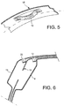
- Figure 5 shows, in perspective, the abutment 10 on the reinforcement 15.
- a stop 10 is less bulky because more punctual than the stop 6 described in Figure 3.
- a major advantage is that the abutment edge formed by the side 11 of the abutment 10 is not impaired because it is obtained by cutting. Its surface is clear, without asperity.
- FIG. 6 shows that the same stop 20 can be formed and used on the crate side 3 for position the latter in relation to the whole constituted by the reinforcement 15 on the body liner 4 by means of its stop 10.
- the two stops 10 and 20 can be in the same plane, which is not possible in the case of the two transverse stampings according to the prior art, as represented by the Figures 2 and 3.
- a method of obtaining this type stop is obtained in one operation vertical stamping. Any other method of obtaining can be used as soon as the 11th side of the stops 10 and 20 has a clean edge and without alteration.
- the front side of the box is mounted on the midfoot structure formed of two reinforcements, a reinforcement accessible from inside the vehicle, and an intermediate reinforcement between this first reinforcement and the cashier side.
Landscapes
- Engineering & Computer Science (AREA)
- Chemical & Material Sciences (AREA)
- Combustion & Propulsion (AREA)
- Transportation (AREA)
- Mechanical Engineering (AREA)
- Body Structure For Vehicles (AREA)
- Automobile Manufacture Line, Endless Track Vehicle, Trailer (AREA)
- Braking Systems And Boosters (AREA)
- Braking Arrangements (AREA)
Abstract
Description
- figure 1, un côté de caisse d'une automobile sur lequel on a localisé l'invention ;
- figure 2, une coupe selon la ligne A-A de la figure 1 d'un élément de carrosserie de l'art antérieur ;
- figure 3, une coupe selon la ligne A-A de
la figure 1 d'un autre élément de carrosserie selon
l'art antérieur ;
ces trois figures étant déjà décrites ; - figure 4, une coupe d'une première réalisation du système selon l'invention ;
- figure 5, une vue partielle cavalière d'une réalisation de l'invention ; et
- figure 6, une coupe d'une deuxième réalisation de l'invention.
Claims (6)
- Système de butée pour le positionnement latéral relatif d'éléments de carrosserie automobile entre un renfort de carrosserie (15) et un autre élément de la carrosserie, le système comprenant au moins une butée (10, 20) obtenue par déformation ponctuelle sur un premier élément de la carrosserie destiné à venir en contact avec un deuxième élément de carrosserie, le renfort de carrosserie (15) constituant l'un de ces deux éléments de carrosserie, caractérisé en ce que la au moins une butée (10, 20) obtenue par déformation partielle est un double crevé formé par deux fentes parallèles longitudinales entre lesquelles la partie découpée est déformée de manière à se trouver vers l'intérieur de l'habitacle, lorsque le premier élément est mis en place.
- Système selon la revendication 1, caractérisé en ce qu'il concerne la jonction du toit (1) et du cadre de portières (2).
- Système selon la revendication 1, caractérisé en ce que le premier élément est le renfort (15) utilisé entre une doublure de caisse (4) et le côté de caisse (3, 13), le deuxième élément étant la doublure de caisse (4).
- Système selon la revendication 3, caractérisé en ce que le côté de caisse (13) possède également une butée (20) constituée par une déformation en double crevé, formée par deux fentes parallèles longitudinales entre lesquelles la partie découpée est déformée vers l'intérieur de l'habitacle, lorsqu'elle est positionnée contre l'ensemble constitué du renfort (15) et de la doublure de caisse (4).
- Système selon la revendication 1, caractérisé en ce que le premier élément est le côté de caisse (13) portant la butée (20), le deuxième élément étant le renfort de carrosserie (15) placé entre le côté de caisse (3) et la doublure de caisse (4).
- Système selon la revendication 1, caractérisé en ce que la au moins une butée (10, 20) est obtenue par emboutissage.
Applications Claiming Priority (2)
| Application Number | Priority Date | Filing Date | Title |
|---|---|---|---|
| FR0350528A FR2859695B1 (fr) | 2003-09-12 | 2003-09-12 | Systeme de butee pour le positionnemnt lateral relatif d'elements de carrosserie automobile |
| FR0350528 | 2003-09-12 |
Publications (2)
| Publication Number | Publication Date |
|---|---|
| EP1514778A1 true EP1514778A1 (fr) | 2005-03-16 |
| EP1514778B1 EP1514778B1 (fr) | 2008-07-02 |
Family
ID=34130857
Family Applications (1)
| Application Number | Title | Priority Date | Filing Date |
|---|---|---|---|
| EP04300552A Expired - Lifetime EP1514778B1 (fr) | 2003-09-12 | 2004-08-23 | Système de butée pour le positionnement latéral relatif d'éléments de carrosserie automobile |
Country Status (5)
| Country | Link |
|---|---|
| EP (1) | EP1514778B1 (fr) |
| AT (1) | ATE399701T1 (fr) |
| DE (1) | DE602004014690D1 (fr) |
| ES (1) | ES2305696T3 (fr) |
| FR (1) | FR2859695B1 (fr) |
Citations (2)
| Publication number | Priority date | Publication date | Assignee | Title |
|---|---|---|---|---|
| DE3150027A1 (de) * | 1980-06-25 | 1983-06-23 | Volkswagenwerk Ag, 3180 Wolfsburg | "anordnung mit einem dach und seitenteil einer karosserie verbindenden flansch und einer auf ihm befestigten dicht- und abdeckleiste" |
| DE19714631A1 (de) * | 1996-04-20 | 1997-10-30 | Volkswagen Ag | Selbsttragende Kraftfahrzeugkarosserie |
-
2003
- 2003-09-12 FR FR0350528A patent/FR2859695B1/fr not_active Expired - Fee Related
-
2004
- 2004-08-23 AT AT04300552T patent/ATE399701T1/de not_active IP Right Cessation
- 2004-08-23 EP EP04300552A patent/EP1514778B1/fr not_active Expired - Lifetime
- 2004-08-23 DE DE602004014690T patent/DE602004014690D1/de not_active Expired - Lifetime
- 2004-08-23 ES ES04300552T patent/ES2305696T3/es not_active Expired - Lifetime
Patent Citations (2)
| Publication number | Priority date | Publication date | Assignee | Title |
|---|---|---|---|---|
| DE3150027A1 (de) * | 1980-06-25 | 1983-06-23 | Volkswagenwerk Ag, 3180 Wolfsburg | "anordnung mit einem dach und seitenteil einer karosserie verbindenden flansch und einer auf ihm befestigten dicht- und abdeckleiste" |
| DE19714631A1 (de) * | 1996-04-20 | 1997-10-30 | Volkswagen Ag | Selbsttragende Kraftfahrzeugkarosserie |
Also Published As
| Publication number | Publication date |
|---|---|
| FR2859695B1 (fr) | 2005-11-11 |
| DE602004014690D1 (de) | 2008-08-14 |
| ATE399701T1 (de) | 2008-07-15 |
| FR2859695A1 (fr) | 2005-03-18 |
| EP1514778B1 (fr) | 2008-07-02 |
| ES2305696T3 (es) | 2008-11-01 |
Similar Documents
| Publication | Publication Date | Title |
|---|---|---|
| EP0720935B1 (fr) | Dispositif pour le positionnement précis d'un pare-chocs sur une aile d'un véhicule | |
| FR3041905A1 (fr) | Dispositif vitre affleurant pour porte de vehicule, porte, vehicule automobile, procede de fabrication et dispositif d'etancheite correspondants. | |
| WO2014027150A1 (fr) | Structure de porte de véhicule automobile munie d'un renfort, renfort, porte équipée de la structure de porte et véhicule associés | |
| EP1514778B1 (fr) | Système de butée pour le positionnement latéral relatif d'éléments de carrosserie automobile | |
| FR2881995A1 (fr) | Ensemble de vitrages encapsules pour un vehicule automobile, procede de pose d'un tel ensemble de vitrages encapsules et vehicule automobile comportant un tel ensemble de vitrages encapsules | |
| EP2812230B1 (fr) | Structure de montage d'un poste de conduite d'un vehicule | |
| EP1819543B1 (fr) | Raidisseur de panneau de porte | |
| EP1846192A1 (fr) | Procede d'assemblage d'un pavillon de vehicule automobile et moyens associes | |
| EP3489118B1 (fr) | Dispositif d ajustement en position d'un becquet rapporté de véhicule automobile | |
| FR2800698A1 (fr) | Pied avant de vehicule automobile realise en une unique piece | |
| EP3877239B1 (fr) | Agencement avec une structure latérale de véhicule et procédé de réalisation d'un tel agencement | |
| FR2800697A1 (fr) | Poutre de vehicule automobile integrant un montant de baie et un brancard de pavillon | |
| EP3055192B1 (fr) | Dispositif de fixation d'une traverse de poste de conduite d'un vehicule automobile | |
| EP4077104B1 (fr) | Tablette structurelle pour véhicule automobile | |
| FR3141408A1 (fr) | Système d’habillage d’un volet de véhicule automobile et procédé d’assemblage associé. | |
| EP1844985B1 (fr) | Dispositif de retenue et d'articulation de tablette arrière pour véhicule automobile | |
| EP4091849A1 (fr) | Caisse pour véhicule utilitaire comprenant une porte coulissante équipée d'un moyen de rétention | |
| EP3831629A1 (fr) | Dispositif d'étanchéité bi-injecté avec crochet | |
| FR2661972A1 (fr) | Armature pour profile utilisable, en particulier, dans l'industrie automobile. | |
| FR3083756A1 (fr) | Guide d'air pour vehicule automobile realise d'une piece en materiau polymere expanse et comportant au moins une zone frangible | |
| FR2749525A1 (fr) | Outillage pour former des signes dans une plaque signaletique du type double | |
| FR3160378A1 (fr) | ensemble de plancher pour véhicule automobile | |
| FR3081796A1 (fr) | Entretoise de fixation d’une poignee de maintient et vehicule automobile comportant une telle entretoise | |
| FR3091228A1 (fr) | système d'essuyage pour véhicule automobile | |
| FR2940932A1 (fr) | Dispositif d'indexage d'une vitre arriere sur le volet arriere d'un vehicule automobile et vehicule comportant une vitre arriere montee sur le volet arriere au moyen d'un tel dispositif d'indexage |
Legal Events
| Date | Code | Title | Description |
|---|---|---|---|
| PUAI | Public reference made under article 153(3) epc to a published international application that has entered the european phase |
Free format text: ORIGINAL CODE: 0009012 |
|
| AK | Designated contracting states |
Kind code of ref document: A1 Designated state(s): AT BE BG CH CY CZ DE DK EE ES FI FR GB GR HU IE IT LI LU MC NL PL PT RO SE SI SK TR |
|
| AX | Request for extension of the european patent |
Extension state: AL HR LT LV MK |
|
| 17P | Request for examination filed |
Effective date: 20050726 |
|
| AKX | Designation fees paid |
Designated state(s): AT BE BG CH CY CZ DE DK EE ES FI FR GB GR HU IE IT LI LU MC NL PL PT RO SE SI SK TR |
|
| GRAP | Despatch of communication of intention to grant a patent |
Free format text: ORIGINAL CODE: EPIDOSNIGR1 |
|
| GRAS | Grant fee paid |
Free format text: ORIGINAL CODE: EPIDOSNIGR3 |
|
| GRAA | (expected) grant |
Free format text: ORIGINAL CODE: 0009210 |
|
| AK | Designated contracting states |
Kind code of ref document: B1 Designated state(s): AT BE BG CH CY CZ DE DK EE ES FI FR GB GR HU IE IT LI LU MC NL PL PT RO SE SI SK TR |
|
| REG | Reference to a national code |
Ref country code: GB Ref legal event code: FG4D Free format text: NOT ENGLISH |
|
| REG | Reference to a national code |
Ref country code: CH Ref legal event code: EP |
|
| REF | Corresponds to: |
Ref document number: 602004014690 Country of ref document: DE Date of ref document: 20080814 Kind code of ref document: P |
|
| REG | Reference to a national code |
Ref country code: IE Ref legal event code: FG4D Free format text: LANGUAGE OF EP DOCUMENT: FRENCH |
|
| PG25 | Lapsed in a contracting state [announced via postgrant information from national office to epo] |
Ref country code: SI Free format text: LAPSE BECAUSE OF FAILURE TO SUBMIT A TRANSLATION OF THE DESCRIPTION OR TO PAY THE FEE WITHIN THE PRESCRIBED TIME-LIMIT Effective date: 20080702 |
|
| REG | Reference to a national code |
Ref country code: ES Ref legal event code: FG2A Ref document number: 2305696 Country of ref document: ES Kind code of ref document: T3 |
|
| PG25 | Lapsed in a contracting state [announced via postgrant information from national office to epo] |
Ref country code: NL Free format text: LAPSE BECAUSE OF FAILURE TO SUBMIT A TRANSLATION OF THE DESCRIPTION OR TO PAY THE FEE WITHIN THE PRESCRIBED TIME-LIMIT Effective date: 20080702 |
|
| NLV1 | Nl: lapsed or annulled due to failure to fulfill the requirements of art. 29p and 29m of the patents act | ||
| PG25 | Lapsed in a contracting state [announced via postgrant information from national office to epo] |
Ref country code: PT Free format text: LAPSE BECAUSE OF FAILURE TO SUBMIT A TRANSLATION OF THE DESCRIPTION OR TO PAY THE FEE WITHIN THE PRESCRIBED TIME-LIMIT Effective date: 20081202 |
|
| REG | Reference to a national code |
Ref country code: IE Ref legal event code: FD4D |
|
| PG25 | Lapsed in a contracting state [announced via postgrant information from national office to epo] |
Ref country code: FI Free format text: LAPSE BECAUSE OF FAILURE TO SUBMIT A TRANSLATION OF THE DESCRIPTION OR TO PAY THE FEE WITHIN THE PRESCRIBED TIME-LIMIT Effective date: 20080702 Ref country code: BG Free format text: LAPSE BECAUSE OF FAILURE TO SUBMIT A TRANSLATION OF THE DESCRIPTION OR TO PAY THE FEE WITHIN THE PRESCRIBED TIME-LIMIT Effective date: 20081002 Ref country code: AT Free format text: LAPSE BECAUSE OF FAILURE TO SUBMIT A TRANSLATION OF THE DESCRIPTION OR TO PAY THE FEE WITHIN THE PRESCRIBED TIME-LIMIT Effective date: 20080702 |
|
| PG25 | Lapsed in a contracting state [announced via postgrant information from national office to epo] |
Ref country code: MC Free format text: LAPSE BECAUSE OF NON-PAYMENT OF DUE FEES Effective date: 20080831 |
|
| REG | Reference to a national code |
Ref country code: CH Ref legal event code: PL |
|
| PG25 | Lapsed in a contracting state [announced via postgrant information from national office to epo] |
Ref country code: IE Free format text: LAPSE BECAUSE OF FAILURE TO SUBMIT A TRANSLATION OF THE DESCRIPTION OR TO PAY THE FEE WITHIN THE PRESCRIBED TIME-LIMIT Effective date: 20080702 Ref country code: EE Free format text: LAPSE BECAUSE OF FAILURE TO SUBMIT A TRANSLATION OF THE DESCRIPTION OR TO PAY THE FEE WITHIN THE PRESCRIBED TIME-LIMIT Effective date: 20080702 Ref country code: DK Free format text: LAPSE BECAUSE OF FAILURE TO SUBMIT A TRANSLATION OF THE DESCRIPTION OR TO PAY THE FEE WITHIN THE PRESCRIBED TIME-LIMIT Effective date: 20080702 |
|
| PLBE | No opposition filed within time limit |
Free format text: ORIGINAL CODE: 0009261 |
|
| STAA | Information on the status of an ep patent application or granted ep patent |
Free format text: STATUS: NO OPPOSITION FILED WITHIN TIME LIMIT |
|
| PG25 | Lapsed in a contracting state [announced via postgrant information from national office to epo] |
Ref country code: CZ Free format text: LAPSE BECAUSE OF FAILURE TO SUBMIT A TRANSLATION OF THE DESCRIPTION OR TO PAY THE FEE WITHIN THE PRESCRIBED TIME-LIMIT Effective date: 20080702 Ref country code: RO Free format text: LAPSE BECAUSE OF FAILURE TO SUBMIT A TRANSLATION OF THE DESCRIPTION OR TO PAY THE FEE WITHIN THE PRESCRIBED TIME-LIMIT Effective date: 20080702 Ref country code: SK Free format text: LAPSE BECAUSE OF FAILURE TO SUBMIT A TRANSLATION OF THE DESCRIPTION OR TO PAY THE FEE WITHIN THE PRESCRIBED TIME-LIMIT Effective date: 20080702 |
|
| 26N | No opposition filed |
Effective date: 20090403 |
|
| PG25 | Lapsed in a contracting state [announced via postgrant information from national office to epo] |
Ref country code: CH Free format text: LAPSE BECAUSE OF NON-PAYMENT OF DUE FEES Effective date: 20080831 Ref country code: LI Free format text: LAPSE BECAUSE OF NON-PAYMENT OF DUE FEES Effective date: 20080831 |
|
| REG | Reference to a national code |
Ref country code: FR Ref legal event code: ST Effective date: 20090630 |
|
| PG25 | Lapsed in a contracting state [announced via postgrant information from national office to epo] |
Ref country code: BE Free format text: LAPSE BECAUSE OF NON-PAYMENT OF DUE FEES Effective date: 20080831 |
|
| PG25 | Lapsed in a contracting state [announced via postgrant information from national office to epo] |
Ref country code: FR Free format text: LAPSE BECAUSE OF NON-PAYMENT OF DUE FEES Effective date: 20080901 |
|
| PG25 | Lapsed in a contracting state [announced via postgrant information from national office to epo] |
Ref country code: SE Free format text: LAPSE BECAUSE OF FAILURE TO SUBMIT A TRANSLATION OF THE DESCRIPTION OR TO PAY THE FEE WITHIN THE PRESCRIBED TIME-LIMIT Effective date: 20081002 |
|
| PG25 | Lapsed in a contracting state [announced via postgrant information from national office to epo] |
Ref country code: PL Free format text: LAPSE BECAUSE OF FAILURE TO SUBMIT A TRANSLATION OF THE DESCRIPTION OR TO PAY THE FEE WITHIN THE PRESCRIBED TIME-LIMIT Effective date: 20080702 |
|
| PG25 | Lapsed in a contracting state [announced via postgrant information from national office to epo] |
Ref country code: LU Free format text: LAPSE BECAUSE OF NON-PAYMENT OF DUE FEES Effective date: 20080823 Ref country code: HU Free format text: LAPSE BECAUSE OF FAILURE TO SUBMIT A TRANSLATION OF THE DESCRIPTION OR TO PAY THE FEE WITHIN THE PRESCRIBED TIME-LIMIT Effective date: 20090103 Ref country code: CY Free format text: LAPSE BECAUSE OF FAILURE TO SUBMIT A TRANSLATION OF THE DESCRIPTION OR TO PAY THE FEE WITHIN THE PRESCRIBED TIME-LIMIT Effective date: 20080702 |
|
| PG25 | Lapsed in a contracting state [announced via postgrant information from national office to epo] |
Ref country code: GR Free format text: LAPSE BECAUSE OF FAILURE TO SUBMIT A TRANSLATION OF THE DESCRIPTION OR TO PAY THE FEE WITHIN THE PRESCRIBED TIME-LIMIT Effective date: 20081003 |
|
| PGFP | Annual fee paid to national office [announced via postgrant information from national office to epo] |
Ref country code: GB Payment date: 20160819 Year of fee payment: 13 Ref country code: DE Payment date: 20160822 Year of fee payment: 13 Ref country code: IT Payment date: 20160825 Year of fee payment: 13 |
|
| PGFP | Annual fee paid to national office [announced via postgrant information from national office to epo] |
Ref country code: TR Payment date: 20160721 Year of fee payment: 13 Ref country code: ES Payment date: 20160810 Year of fee payment: 13 |
|
| REG | Reference to a national code |
Ref country code: DE Ref legal event code: R119 Ref document number: 602004014690 Country of ref document: DE |
|
| GBPC | Gb: european patent ceased through non-payment of renewal fee |
Effective date: 20170823 |
|
| PG25 | Lapsed in a contracting state [announced via postgrant information from national office to epo] |
Ref country code: DE Free format text: LAPSE BECAUSE OF NON-PAYMENT OF DUE FEES Effective date: 20180301 Ref country code: GB Free format text: LAPSE BECAUSE OF NON-PAYMENT OF DUE FEES Effective date: 20170823 |
|
| PG25 | Lapsed in a contracting state [announced via postgrant information from national office to epo] |
Ref country code: IT Free format text: LAPSE BECAUSE OF NON-PAYMENT OF DUE FEES Effective date: 20170823 |
|
| REG | Reference to a national code |
Ref country code: ES Ref legal event code: FD2A Effective date: 20181029 |
|
| PG25 | Lapsed in a contracting state [announced via postgrant information from national office to epo] |
Ref country code: ES Free format text: LAPSE BECAUSE OF NON-PAYMENT OF DUE FEES Effective date: 20170824 |
|
| PG25 | Lapsed in a contracting state [announced via postgrant information from national office to epo] |
Ref country code: TR Free format text: LAPSE BECAUSE OF NON-PAYMENT OF DUE FEES Effective date: 20170823 |