Background of the Invention
The present invention relates to a moving
member fixing apparatus which moves a moving member,
fixed to and released from a stationary member, in a
released state with respect to the stationary member.
As the most typical example of a moving member
fixing apparatus of this type, a printing switching
apparatus for a sheet-fed offset rotary printing press
with a convertible press mechanism is available which
can perform both single-sided printing and double-sided
printing with one printing press. Such a printing
switching apparatus has a drive connecting/disconnecting
means for connecting and disconnecting drive connection
from an auxiliary motor to a moving cam, and a
fixing/releasing means for fixing and releasing the
moving cam to and from a stationary cam. In this
structure, to adjust the opening/closing timing of the
gripper of an impression cylinder, the moving cam in
contact with a cam follower that opens and closes the
gripper is moved toward the surface of the impression
cylinder, to adjust the phase of the moving cam.
A conventional moving member fixing apparatus
has a moving cam fixing air cylinder serving as a
fixing/releasing means for fixing and releasing a moving
cam to and from a stationary cam, an auxiliary motor
which moves the moving cam to adjust the phase with
respect to the stationary cam, and a gear connecting air
cylinder serving as a drive connecting/disconnecting
means for transmitting and disconnecting the drive of
the auxiliary motor to the moving cam. In this
structure, the drive of the auxiliary motor can be
transmitted to the moving cam through the gear
connecting air cylinder. Then, the moving cam fixing
air cylinder releases the moving cam from the stationary
cam, and the auxiliary motor is driven, so that the
moving cam is switched to a phase for double-sided
printing (see Japanese Patent Laid-Open No. 2000-52535).
The conventional moving member fixing
apparatus requires two air cylinders, i.e., the moving
cam fixing air cylinder serving as the fixing/releasing
means for fixing and releasing the moving cam to and
from the stationary cam, and the gear connecting air
cylinder which transmits or disconnects the drive of the
auxiliary motor to the moving cam. Accordingly, not
only the number of components increases, but also the
apparatus becomes large in size and the structure is
complicated.
Summary of the Invention
It is an object of the present invention to
provide a moving member fixing apparatus in which the
number of components is decreased, so that the apparatus
is downsized and the structure is simplified.
In order to achieve the above object,
according to the present invention, there is provided a
moving member fixing apparatus comprising a stationary
member, a moving member movable with respect to the
stationary member, driving means, drive-connected to the
moving member, for moving the moving member with respect
to the stationary member, drive connecting/disconnecting
means for connecting/disconnecting drive connection from
the driving means to the moving member, fixing/releasing
means for fixing and releasing the moving member with
respect to the stationary member, and an actuator which
drives the drive connecting/disconnecting means and
fixing/releasing means.
Brief Description of the Drawings
Fig. 1 is a cutaway front view showing a
moving member fixing apparatus according to the first
embodiment of the present invention;
Fig. 2 is a view seen from a direction of an
arrow II of Fig. 1;
Fig. 3 is a sectional view taken along the
line III - III of Fig. 2;
Fig. 4 is a sectional view seen from the line
of arrows IV - IV of Fig. 2;
Fig. 5 is a view seen from a direction of an
arrow V of Fig. 1;
Fig. 6 is a cutaway front view showing a
moving member fixing apparatus according to the second
embodiment of the present invention; and
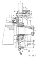
Fig. 7 is a cutaway front view showing a
moving member fixing apparatus according to the third
embodiment of the present invention.
Description of the Preferred Embodiments
A moving member fixing apparatus according to
the first embodiment of the present invention will be
described with reference to Figs. 1 to 5.
Referring to Fig. 1, an end shaft 4 of an
impression cylinder 1 is rotatably, axially supported by
a bearing 3 fixed to a frame 2 of a printing press. A
cylinder gear (first driving gear) 5 driven to rotate by
a printing press motor 9 is fixed to the distal end of
the end shaft 4. A cam follower 7 pivotally supported
by a cam lever 6 is fixed to the end of the impression
cylinder 1. The cam follower 7 is biased by the
torsional moment of a torsion bar 8 having one end fixed
to the other end (not shown) side of the impression
cylinder 1, in directions to engage with a stationary
cam 10 serving as a stationary member (to be described
later) and a moving cam 12 serving as a moving member.
When the cam follower 7 engages with the cam
10 or 12, the gripper (not shown) of the impression
cylinder 1 is opened and closed. The cam follower 7
engages with the stationary cam 10 when transferring a
sheet with a cylinder upstream in a sheet convey
direction of the impression cylinder 1, to open and
close the gripper. The cam follower 7 engages with the
moving cam 12 when transferring a sheet with a cylinder
downstream in the sheet convey direction of the
impression cylinder 1, to open and close the gripper.
The stationary cam 10 is fixed to the frame 2
through a ring member 11. The moving cam 12 is fixed to
a large-diameter gear (second driving gear) 13 rotatably
supported by the ring member 11. When a
fixing/releasing device 25 (to be described later)
brings the opposing surfaces of the stationary cam 10
and moving cam 12 into contact with each other, the
moving cam 12 is fixed to the stationary cam 10, and
rotation of the large-diameter gear 13 is regulated.
When the fixing/releasing device 25 releases the moving
cam 12 from the stationary cam 10, phase change
(movement) of the moving cam 12 and stationary cam 10
through the large-diameter gear 13 with respect to the
circumferential direction of the impression cylinder 1
is enabled.
A drive connecting/disconnecting mechanism 15
which connects/disconnects the drive between the
cylinder gear 5 (printing press motor 9) and
large-diameter gear 13 will be described.
As shown in Fig. 2, the drive
connecting/disconnecting mechanism 15 includes a first
lever 42 (to be described later) which is driven to
swing by an air (fluid pressure) cylinder 30 serving as
an actuator, a second lever 44 (to be described later)
which is connected to the first lever 42 and pivots, a
shaft 16 which is driven by the pivot motion of the
second lever 44 and moves in the axial direction, and a
gear (first connection gear) 20 which is fixed to the
shaft 16 and meshes in a connected state with the
cylinder gear 5. When a second wheel 54 engages with an
engaging member 21 and presses it, the shaft 16 moves in
a direction to come close to the cylinder gear 5, and
the cylinder gear 5 and gear 20 mesh with each other.
When the second wheel 54 engages with a stopper 22 and
presses it, the shaft 16 moves in a direction to
separate from the cylinder gear 5, and the cylinder gear
5 and gear 20 disengage from each other.
The shaft 16 is supported between the frame 2
and a support plate 18 fixed to the frame 2 through
studs 17, to be rotatable and movable in the axial
direction. A gear (second connection gear) 19 having a
large facewidth so as to mesh with the large-diameter
gear 13 constantly is fixed to one end of the shaft 16
which projects inside the frame 2. The gear 20 which
meshes with or disengages from the cylinder gear 5 is
fixed through the engaging member 21 to the other end of
the shaft 16 which projects outside the frame 2. A
stopper 22 is fixed to the shaft 16 at a predetermined
space from the engaging member 21.
The fixing/releasing device 25 which fixes and
releases the moving cam 12 with respect to the
stationary cam 10 will be described.
As shown in Figs. 1 and 5, the
fixing/releasing device 25 includes a press member 26
which presses the moving cam 12 against the stationary
cam 10, a lever 27 which engages with the press member
26, a coned disc spring 28 serving as a biasing means
for biasing the lever 27 in a direction to press the
press member 26, and the first lever 42 which releases
the press operation of the lever 27 for the press member
26 against the biasing force of the coned disc spring 28.
The first lever 42 is one of elements that form the
drive connecting/disconnecting mechanism 15, as
described above, and is driven by the air cylinder 30.
The press member 26 is slidably supported in a
through hole 31 (Fig. 1) formed in the frame 2, such
that one end of the press member 26 projects outside the
frame 2 from the through hole 31. As shown in Fig. 5, a
pair of support plates 32 are fixed to the frame 2 so as
to oppose each other at a gap. A shaft 33 horizontally
extends between the pair of support plates 32. The
lever 27 is supported to be pivotal clockwise and
counterclockwise in Fig. 1 about the shaft 33 as the
pivot center. The press member 26 is in contact with
one end of the lever 27.
As shown in Fig. 1, a blind hole 36 in which a
press element 37 fits slidably is formed at the center
of a recess 35 of the frame 2. The press element 37
threadably engages with a tapped hole 27a formed in one
end of the lever 27, and has a flange 38 at its end
exposed from the blind hole 36. A screw 39 which
threadably engages with a tapped hole 27a formed in the
other end of the lever 27 integrally projects from the
center of the flange 38. In this state, the press
element 37 is fixed to the lever 27. The coned disc
spring 28 is elastically mounted between the flange 38
of the press element 37 and the bottom of the recess 35.
The spring force of the coned disc spring 28 biases the
lever 27 counterclockwise through the press element 37
about the shaft 33 as the pivot center.
When the lever 27 pivots, the press member 26
engaging with the other end of the e lever 27 moves in a
direction of an arrow A. As the press member 26 moves
in the direction of the arrow A, it presses the
large-diameter gear 13 in the direction of the arrow A.
The moving cam 12 fixed to the large-diameter gear 13
comes into tight contact with the stationary cam 10, so
that the moving cam 12 is fixed to the stationary cam 10.
A length L2 from the shaft 33 to that portion of the
lever 27 which threadably engages with the screw 39 is
set to be larger than a length Li between the shaft 33
and that portion of the lever 27 which engages with the
press member 26.
As shown in Fig. 2, an air cylinder 30 is
pivotally mounted on the upper end of a bracket 41
standing vertically from the frame 2. The first lever
42 having the sectional shape shown in Fig. 3 is
pivotally supported at the side end of the bracket 41
through a pin 43, and the second lever 44 is pivotally
supported at the center of the bracket 41 through a pin
45. The proximal end of the first lever 42 is pivotally
mounted on an actuating rod 47 of the air cylinder 30
through a pin 48. The first lever 42 has two swing ends,
i.e., first and second swing ends 49 and 50. The
tensile force of a tensile coil spring 51 suspending
between the first lever 42 and bracket 41 biases the
first lever 42 clockwise about the pin 43 as the pivot
center.
A first wheel 52 serving as the first engaging
portion is pivotally supported by the first swing end 49.
The first wheel 52 presses the lever 27 when the
actuating rod 47 of the air cylinder 30 moves forward
and the first lever 42 pivots counterclockwise about the
pin 43 as the pivot center against the tensile force of
the tensile coil spring 51. As the first wheel 52
presses the lever 27, the lever 27 pivots clockwise
(Fig. 1) about the shaft 33 as the pivot center against
the spring force of the coned disc spring 28. Hence,
the moving cam 12 fixed to the stationary cam 10 by the
press member 26 is released.
One end of the second lever 44 is pivotally
mounted on the second swing end 50 of the first lever 42
through a pin 53. As shown in Fig. 4, the second wheel
54 serving as the second engaging portion is pivotally
supported by the other end of the second lever 44
through a pin 55. The second wheel 54 is interposed
between the engaging member 21 of the drive
connecting/disconnecting mechanism 15 and the stopper 22.
When the actuating rod 47 of the air cylinder 30 is
retreated, the second wheel 54 moves the shaft 16 in the
direction of the arrow A through the stopper 22, as
indicated by a solid line in Fig. 2. Hence, the gear 20
and cylinder gear 5 meshing with each other are released,
as shown in Fig. 1.
When the actuating rod 47 of the air cylinder
30 moves forward and the first lever 42 pivots
counterclockwise in Fig. 2 about the pin 43 as the pivot
center, the second lever 44 pivots counterclockwise in
Fig. 2 about the pin 45 as the pivot center. Hence, the
second wheel 54 moves the shaft 16 in the direction of
the arrow B through the engaging member 21, and the gear
20 meshes with the cylinder gear 5, as indicated by an
alternate long and two short dashed line in Fig. 1.
When the actuating rod 47 of the air cylinder
30 moves forward, first, the gear 20 meshes with the
cylinder gear 5 by the drive connecting/disconnecting
mechanism 15. After that, the fixing/releasing device
25 releases the moving cam 12 from the stationary cam 10.
When the actuating rod 47 of the air cylinder 30 moves
backward, first, the fixing/releasing device 25 fixes
the moving cam 12 to the stationary cam 10. After that,
the drive connecting/disconnecting mechanism 15 releases
the gear 20 and cylinder gear 5 from each other.
In the moving member fixing apparatus having
the above structure, the moving operation of the moving
member with respect to the stationary member will be
described.
When the actuating rod 47 of the air cylinder
30 is retreated, as shown in Fig. 1, the moving cam 12
is fixed to the stationary cam 10, and the gear 20 is
released from the cylinder gear 5. In this state, when
the actuating rod 47 of the air cylinder 30 moves
forward, the first lever 42 pivots counterclockwise in
Fig. 2 about the pin 43 as the pivot center against the
tensile force of the tensile coil spring 51. As the
first lever 42 pivots, the second lever 44 pivots
counterclockwise in Fig. 2 about the pin 45 as the pivot
center. Hence, the second wheel 54 engages with the
engaging member 21 and the shaft 16 moves in the
direction of the arrow B. The gear 20 and cylinder gear
5 mesh with each other, as indicated by an alternate
long and two short dashed line in Fig. 1.
When the actuating rod 47 of the air cylinder
30 further moves forward and the first lever 42 pivots
counterclockwise about the pin 43 as the pivot center,
the first wheel 52 presses the lever 27. As the first
wheel 52 presses the lever 27, in Fig. 1, the lever 27
pivots clockwise about the shaft 33 as the pivot center
against the spring force of the coned disc spring 28,
and the moving cam 12 fixed to the stationary cam 10 by
the press member 26 is released.
As described above, the moving cam 12 fixed to
the stationary cam 10 is released after the gear 20 and
cylinder gear 5 mesh with each other (drive connection
is connected) . Therefore, the moving cam 12 will not
become rotatable temporarily, and a positional shift in
the rotational direction of the moving cam 12 can be
regulated.
Subsequently, the cylinder gear 5 meshing with
the gear 20 is pivoted by the printing press motor 9 for
a predetermined amount, so the large-diameter gear 13
pivots for a predetermined amount through the gear 20,
shaft 16, and gear 19. At this time, the moving cam 12
also moves integrally for a predetermined amount, and
phase adjustment for the stationary cam 10 is performed.
Then, when the actuating rod 47 of the air cylinder 30
moves backward, the lever 42 pivots clockwise in Fig. 2
about the pin 43 as the pivot center to locate at the
position indicated by a solid line in Fig. 2, to release
the lever 27 from the first wheel 52.
The released lever 27 is pivoted
counterclockwise in Fig. 1 about the shaft 33 as the
pivot center by the spring force of the coned disc
spring 28. One end of the lever 27 moves the press
member 26 in the direction of the arrow A, so that the
press member 26 presses the moving cam 12 against the
stationary cam 10. Hence, the moving cam 12 is fixed to
the stationary cam 10. Subsequently, when the actuating
rod 47 of the air cylinder 30 moves backward, the second
lever 44 pivots clockwise in Fig. 2 about the pin 45 as
the pivot center. As the second lever 44 pivots, the
second wheel 54 moves in the direction of the arrow A in
Fig. 1, to release the gear 20 and cylinder gear 5 from
each other.
As described above, after the moving cam 12 is
fixed to the stationary cam 10, the gear 20 and cylinder
gear 5 are released (drive connection is disconnected)
from each other. Once the phase of the moving cam 12
with respect to the stationary cam 10 is adjusted, the
moving cam 12 will not shift. Thus, accurate phase
adjustment can be performed.
According to this embodiment, fixing/releasing
of the moving cam 12 with respect to the stationary cam
10 and connection/disconnection of drive to move the
moving cam 12 with respect to the stationary cam 10 are
performed with one air cylinder 30. Thus, the number of
components is decreased, so that the apparatus can be
downsized and the structure can be simplified.
The length L2 from the shaft 33 to that
portion of the lever 27 which threadably engages with
the screw 39 is set larger than the length Li from the
shaft 33 to that portion of the lever 27 which engages
with the press member 26, so that the principle of lever
can be employed. With the leverage, the spring force of
the coned disc spring 28 is amplified to press the press
member 26. Thus, the spring force of the coned disc
spring 28 can be decreased. The driving force of the
air cylinder 30 itself which pivots the lever 27 against
the spring force of the coned disc spring 28 can also be
decreased. Consequently, as the air cylinder 30, one
having a small outer size can be used, and the space in
the apparatus where the air cylinder 30 is to be
installed can be decreased.
When the drive connecting/disconnecting
mechanism 15 performs disconnection, the cylinder gear 5
and gear 20 can be released from each other. Thus,
early wear of the gears 5 and 20 can be prevented.
A moving member fixing apparatus according to
the second embodiment of the present invention will be
described with reference to Fig. 6.
In the second embodiment, even when a shaft 16
moves in directions of arrows A and B, a gear 20 keeps
meshing with a cylinder gear 5. A gear 19 meshes with a
large-diameter gear 13 when the shaft 16 moves in the
direction of the arrow B, and releases from the
large-diameter gear 13 when the shaft 16 moves in the
direction of the arrow A. With this arrangement, as the
shaft 16 is moved in the direction of the arrow B and
the cylinder gear 5 is driven to rotate by a printing
press motor 9, the phase of a moving cam 12 with respect
to a stationary cam 10 is adjusted.
A moving member fixing apparatus according to
the third embodiment of the present invention will be
described with reference to Fig. 7.
In the third embodiment, when a shaft 16 moves
in a direction of an arrow B, a gear 19 meshes with a
large-diameter gear 13, and a gear 20 meshes with a
cylinder gear 5. In this state, when a printing press
motor 9 is driven to rotate the cylinder gear 5, the
phase of a moving cam 12 with respect to a stationary
cam 10 is adjusted. When the shaft 16 moves in a
direction of an arrow A, the gear 19 is released from
the large-diameter gear 13, and the gear 20 is released
from the cylinder gear 5.
In the respective embodiments described above,
a printing switching apparatus for a sheet-fed offset
rotary printing press with a convertible press mechanism
is described. The present invention can also be applied
to phase adjustment for a cam in a folding machine and
coater switching device for a coater apparatus. The
moving cam 12 is fixed to the stationary cam 10.
Alternatively, in an apparatus that does not require a
stationary cam, a frame can be used as a target to be
fixed.
The stationary cam 10 and moving cam 12 are
used as the stationary member and moving member,
respectively. Alternatively, in a stationary gear and
moving gear provided to a convertible cylinder, the
moving gear may be fixed to and released from the
stationary gear. The second lever 44 is supported by
the second swing end 50 of the first lever 42 through
the pin 53. Alternatively, no second swing end 50 need
be provided, and the second lever 44 may be supported by
any portion of the first lever 42 through the pin 53.
The second wheel 54 supported by the second
lever 44 is interposed between the engaging member 21
supported by the shaft 16 and the stopper 22. However,
the present invention is not limited to this. More
specifically, the second wheel 54 may be supported by
the shaft 16. An engaging member to clamp the second
wheel 54 may be provided to the second lever 44. The
second wheel 54 may be clamped by the engaging member,
so that the shaft 16 may be moved.
The first wheel 52 is provided to the first
lever 42. Alternatively, the first wheel 52 may be
supported by the lever 27. No first wheel 52 need be
provided, and the lever 27 may be swung by the first
lever 42 directly.
The two gears 19 and 20 are used between the
cylinder gear 5 and large-diameter gear 13.
Alternatively, only one common gear may be used. In
this case, in the connected state, the cylinder gear 5
and large-diameter gear 13 mesh with the common gear
simultaneously. In the disconnected state, at least one
of the cylinder gear 5 and large-diameter gear 13
meshing with the common gear is released. The gears 19
and 20 are fixed to the shaft 16. Alternatively, the
gears 19 and 20 may be slidably supported by the shaft.
In this case, the gears 19 and 20 may move in the axial
direction of the shaft while they are drive-connected to
each other.
When the rod 47 of the air cylinder 30
stretches, the lever 42 swings to the position (Fig. 2)
indicated by an alternate long and two short dashed line.
Alternatively, the air cylinder may be set in the
opposite direction, so that the lever'42 swings in the
same manner when the rod 47 retracts.
According to the present invention, only one
air cylinder is employed to decrease the number of
components, so that the apparatus can be downsized and
the structure can be simplified. As the positional
displacement of the moving member with respect to the
stationary member can be regulated, the moving member
can be positioned accurately.