EP1514566A1 - Syringe including a retaining element with an integral annular rib - Google Patents
Syringe including a retaining element with an integral annular rib Download PDFInfo
- Publication number
- EP1514566A1 EP1514566A1 EP03102725A EP03102725A EP1514566A1 EP 1514566 A1 EP1514566 A1 EP 1514566A1 EP 03102725 A EP03102725 A EP 03102725A EP 03102725 A EP03102725 A EP 03102725A EP 1514566 A1 EP1514566 A1 EP 1514566A1
- Authority
- EP
- European Patent Office
- Prior art keywords
- barrel
- retaining
- tongue
- retaining element
- needle
- Prior art date
- Legal status (The legal status is an assumption and is not a legal conclusion. Google has not performed a legal analysis and makes no representation as to the accuracy of the status listed.)
- Granted
Links
- 230000001360 synchronised effect Effects 0.000 claims description 3
- 239000000463 material Substances 0.000 description 2
- 239000000853 adhesive Substances 0.000 description 1
- 230000001070 adhesive effect Effects 0.000 description 1
- 238000004519 manufacturing process Methods 0.000 description 1
- 238000000034 method Methods 0.000 description 1
Images





Classifications
-
- A—HUMAN NECESSITIES
- A61—MEDICAL OR VETERINARY SCIENCE; HYGIENE
- A61M—DEVICES FOR INTRODUCING MEDIA INTO, OR ONTO, THE BODY; DEVICES FOR TRANSDUCING BODY MEDIA OR FOR TAKING MEDIA FROM THE BODY; DEVICES FOR PRODUCING OR ENDING SLEEP OR STUPOR
- A61M5/00—Devices for bringing media into the body in a subcutaneous, intra-vascular or intramuscular way; Accessories therefor, e.g. filling or cleaning devices, arm-rests
- A61M5/178—Syringes
- A61M5/31—Details
- A61M5/32—Needles; Details of needles pertaining to their connection with syringe or hub; Accessories for bringing the needle into, or holding the needle on, the body; Devices for protection of needles
- A61M5/3205—Apparatus for removing or disposing of used needles or syringes, e.g. containers; Means for protection against accidental injuries from used needles
- A61M5/321—Means for protection against accidental injuries by used needles
- A61M5/322—Retractable needles, i.e. disconnected from and withdrawn into the syringe barrel by the piston
-
- A—HUMAN NECESSITIES
- A61—MEDICAL OR VETERINARY SCIENCE; HYGIENE
- A61M—DEVICES FOR INTRODUCING MEDIA INTO, OR ONTO, THE BODY; DEVICES FOR TRANSDUCING BODY MEDIA OR FOR TAKING MEDIA FROM THE BODY; DEVICES FOR PRODUCING OR ENDING SLEEP OR STUPOR
- A61M5/00—Devices for bringing media into the body in a subcutaneous, intra-vascular or intramuscular way; Accessories therefor, e.g. filling or cleaning devices, arm-rests
- A61M5/178—Syringes
- A61M5/31—Details
- A61M5/32—Needles; Details of needles pertaining to their connection with syringe or hub; Accessories for bringing the needle into, or holding the needle on, the body; Devices for protection of needles
- A61M5/3205—Apparatus for removing or disposing of used needles or syringes, e.g. containers; Means for protection against accidental injuries from used needles
- A61M5/321—Means for protection against accidental injuries by used needles
- A61M5/322—Retractable needles, i.e. disconnected from and withdrawn into the syringe barrel by the piston
- A61M5/3221—Constructional features thereof, e.g. to improve manipulation or functioning
- A61M2005/3223—Means impeding or disabling repositioning of used needles at the syringe nozzle
-
- A—HUMAN NECESSITIES
- A61—MEDICAL OR VETERINARY SCIENCE; HYGIENE
- A61M—DEVICES FOR INTRODUCING MEDIA INTO, OR ONTO, THE BODY; DEVICES FOR TRANSDUCING BODY MEDIA OR FOR TAKING MEDIA FROM THE BODY; DEVICES FOR PRODUCING OR ENDING SLEEP OR STUPOR
- A61M5/00—Devices for bringing media into the body in a subcutaneous, intra-vascular or intramuscular way; Accessories therefor, e.g. filling or cleaning devices, arm-rests
- A61M5/178—Syringes
- A61M5/31—Details
- A61M5/32—Needles; Details of needles pertaining to their connection with syringe or hub; Accessories for bringing the needle into, or holding the needle on, the body; Devices for protection of needles
- A61M5/3205—Apparatus for removing or disposing of used needles or syringes, e.g. containers; Means for protection against accidental injuries from used needles
- A61M5/321—Means for protection against accidental injuries by used needles
- A61M5/322—Retractable needles, i.e. disconnected from and withdrawn into the syringe barrel by the piston
- A61M5/3221—Constructional features thereof, e.g. to improve manipulation or functioning
- A61M2005/3223—Means impeding or disabling repositioning of used needles at the syringe nozzle
- A61M2005/3224—Means to disalign the needle tip and syringe nozzle
-
- A—HUMAN NECESSITIES
- A61—MEDICAL OR VETERINARY SCIENCE; HYGIENE
- A61M—DEVICES FOR INTRODUCING MEDIA INTO, OR ONTO, THE BODY; DEVICES FOR TRANSDUCING BODY MEDIA OR FOR TAKING MEDIA FROM THE BODY; DEVICES FOR PRODUCING OR ENDING SLEEP OR STUPOR
- A61M5/00—Devices for bringing media into the body in a subcutaneous, intra-vascular or intramuscular way; Accessories therefor, e.g. filling or cleaning devices, arm-rests
- A61M5/50—Devices for bringing media into the body in a subcutaneous, intra-vascular or intramuscular way; Accessories therefor, e.g. filling or cleaning devices, arm-rests having means for preventing re-use, or for indicating if defective, used, tampered with or unsterile
- A61M5/5066—Means for preventing re-use by disconnection of piston and piston-rod
- A61M2005/5073—Means for preventing re-use by disconnection of piston and piston-rod by breaking or rupturing the connection parts
-
- A—HUMAN NECESSITIES
- A61—MEDICAL OR VETERINARY SCIENCE; HYGIENE
- A61M—DEVICES FOR INTRODUCING MEDIA INTO, OR ONTO, THE BODY; DEVICES FOR TRANSDUCING BODY MEDIA OR FOR TAKING MEDIA FROM THE BODY; DEVICES FOR PRODUCING OR ENDING SLEEP OR STUPOR
- A61M5/00—Devices for bringing media into the body in a subcutaneous, intra-vascular or intramuscular way; Accessories therefor, e.g. filling or cleaning devices, arm-rests
- A61M5/178—Syringes
- A61M5/31—Details
- A61M5/315—Pistons; Piston-rods; Guiding, blocking or restricting the movement of the rod or piston; Appliances on the rod for facilitating dosing ; Dosing mechanisms
- A61M5/31511—Piston or piston-rod constructions, e.g. connection of piston with piston-rod
-
- A—HUMAN NECESSITIES
- A61—MEDICAL OR VETERINARY SCIENCE; HYGIENE
- A61M—DEVICES FOR INTRODUCING MEDIA INTO, OR ONTO, THE BODY; DEVICES FOR TRANSDUCING BODY MEDIA OR FOR TAKING MEDIA FROM THE BODY; DEVICES FOR PRODUCING OR ENDING SLEEP OR STUPOR
- A61M5/00—Devices for bringing media into the body in a subcutaneous, intra-vascular or intramuscular way; Accessories therefor, e.g. filling or cleaning devices, arm-rests
- A61M5/178—Syringes
- A61M5/31—Details
- A61M5/32—Needles; Details of needles pertaining to their connection with syringe or hub; Accessories for bringing the needle into, or holding the needle on, the body; Devices for protection of needles
- A61M5/34—Constructions for connecting the needle, e.g. to syringe nozzle or needle hub
- A61M5/347—Constructions for connecting the needle, e.g. to syringe nozzle or needle hub rotatable, e.g. bayonet or screw
-
- A—HUMAN NECESSITIES
- A61—MEDICAL OR VETERINARY SCIENCE; HYGIENE
- A61M—DEVICES FOR INTRODUCING MEDIA INTO, OR ONTO, THE BODY; DEVICES FOR TRANSDUCING BODY MEDIA OR FOR TAKING MEDIA FROM THE BODY; DEVICES FOR PRODUCING OR ENDING SLEEP OR STUPOR
- A61M5/00—Devices for bringing media into the body in a subcutaneous, intra-vascular or intramuscular way; Accessories therefor, e.g. filling or cleaning devices, arm-rests
- A61M5/178—Syringes
- A61M5/31—Details
- A61M5/32—Needles; Details of needles pertaining to their connection with syringe or hub; Accessories for bringing the needle into, or holding the needle on, the body; Devices for protection of needles
- A61M5/34—Constructions for connecting the needle, e.g. to syringe nozzle or needle hub
- A61M5/348—Constructions for connecting the needle, e.g. to syringe nozzle or needle hub snap lock, i.e. upon axial displacement of needle assembly
Definitions
- This invention relates to a syringe, and more particularly to a syringe that includes a retaining element, which is formed with an integral annular rib, the annular rib serving as an O-ring.
- a conventional syringe includes a syringe barrel 1, a retaining seat 2, a needle unit 3 connected threadably to the retaining seat 2, and a plunger 4.
- the barrel 1 has an interior chamber 101, a front end opening 102, and a shoulder 103.
- the retaining seat 2 is tubular, and includes an outward flange 201 extending radially and outwardly from a rear end of a cylindrical portion 202, an O-ring 203 sleeved on the cylindrical portion 202, and an inward flange 204 extending radially and inwardly from the cylindrical portion 202 and disposed immediately in front of the outward flange 201.
- the cylindrical portion 202 has an internally threaded front end 205.
- the needle unit 3 includes an externally threaded needle seat 301 engaging threadably the front end 205 of the cylindrical portion 202 of the retaining seat 2, and a needle body 302.
- the plunger 4 is movable within the barrel 1 between a front limit position and a rear limit position, and has an actuation rod portion 401, a piston 402 disposed movably and sealingly within the interior chamber 101 in the barrel 1, and a mushroom-shaped tongue 403 extending forwardly from the piston 402.
- the tongue 403 engages a hole defined by the inward flange 204 of the retaining seat 2 so as to permit synchronous movement of the retaining seat 2, the needle unit 3, and the plunger 4 when the plunger 4 moves back to the rear limit position, thereby retracting the needle body 32 into the barrel 1.
- the tongue 403 has a head that is formed with a slot 404 so as to permit the head to move into the needle seat 301 through the hole defined by the inward flange 103 and so as to prevent removal of the head from the needle seat 301 through the hole defined by the inward flange 103.
- the needle unit 3 can be brought into the barrel 1 by moving the plunger 4 from the front limit position to the rear limit position so as to prevent the needle body 32 from hurting the user.
- the aforesaid conventional syringe suffers from the following disadvantages:
- the object of this invention is to provide a syringe with a retaining seat unit, which includes an annular rib that is formed integrally with a retaining element and that serves as an O-ring so as to overcome the aforesaid disadvantages associated with the prior art.
- a syringe includes a syringe barrel, a retaining seat unit, a needle unit, and a plunger.
- the retaining seat unit has a rigid tubular main body that is disposed within the barrel, and a tubular retaining element that is fixed within the main body and that has an annular outer surface, which is formed with an integral rib.
- the retaining seat unit has a maximum outer diameter at the annular rib so that the annular rib serves as an O-ring.
- the first preferred embodiment of a syringe according to this invention is shown to include a syringe barrel 10, a retaining seat unit 20 disposed in the barrel 10 , a needle unit 30 connected fixedly to the retaining seat unit 20, and a plunger 40 disposed movably within the barrel 10.
- the barrel 10 has a central axis (L), a barrel body 11 with an interior chamber 111, a frontwardly converging front end portion 12 with a uniform-diameter front end opening 121 formed therethrough, a shoulder 13 formed between the front end opening 121 and the interior chamber 111, and an annular groove 13 formed in an inner surface of a front end of the barrel body 11.
- the barrel body 11 has a rear end that is formed with an integral inward flange 15 which extends radially and inwardly therefrom and which defines a rear clamping hole 16.
- the retaining seat unit 20 is disposed in a front end of the barrel 10, and includes a unitary, rigid tubular main body 23 made of a plastic material and disposed within the barrel 10, and a unitary, tubular retaining element 24 made of rubber and fixed within the main body 23.
- the main body 23 has a rear end that is formed with an integral outward flange 231, a front cylindrical portion 232, and four projections 236 (see Fig. 4) extending rearwardly from the outward flange 231.
- the outward flange 231 of the main body 23 abuts against the shoulder 13 of the barrel 10.
- the retaining element 24 has a rear end that is formed with an outward flange 241 and a rear inward flange 242, and a front end, which is disposed within the main body 23, which extends into the front end opening 121 in the barrel 10, and which is formed with a front inward flange 243.
- the inward flanges 243, 242 define respectively front and rear clamping holes (243H, 242H), which are coaxial with the barrel 10.
- the retaining element 24 is molded on the main body 23 so that the outward flange 241 of the retaining element 24 is secured to the projections 236 of the main body 23.
- annular rib (23R) is formed on an annular outer surface of the outward flange 241 of the retaining element 24, and has an outer diameter (D) that is greater than the outer diameter (d) of the outward flanges 231, 241 of the main body 23 and the retaining element 24, as shown in Fig. 3. That is to say, the retaining seat unit 20 has a maximum outer diameter at the annular rib (23R).
- the annular rib (23R) engages the annular groove 14 in the barrel 10 so as to anchor the retaining seat unit 20 within the barrel 10, and serves as an O-ring so as to establish a liquid-tight seal between the barrel 10 and the retaining seat unit 20.
- the needle unit 30 includes a needle seat 31, a needle body 32 inserted into and fixed within the needle seat 31 by an adhesive material (H) , and a cover body 33 sleeved on the needle seat 31 and the needle body 32.
- the needle seat 31 has a mushroom-shaped tongue 311 at a rear end, and an outward flange 312 abutting against a rear end of the cover body 33.
- the tongue 311 has a uniform-diameter front tongue portion (311F) extending through the front clamping hole (243H), and a large-diameter rear tongue portion (311R) connected to a rear end of the front tongue portion (311F) and having a maximum diameter greater than the diameter of the front tongue portion (311F).
- the rear tongue portion 311R abuts against a rear end of the front inward flange 243 of the retaining seat unit 24 so as to retain the needle seat 31 on the retaining seat unit 20.
- the rear tongue portion (311R) of the tongue 311 of the needle seat 31 has a frusto-conical rear end (311T), and the front clamping hole (243H) in the retaining element 24 has a frusto-conical front end (243T) so as to guide the tongue 311 of the needle seat 31 to engage the front clamping hole (243H) in the retaining element 24.
- the plunger 40 is disposed within the barrel 10, is located behind the retaining seat unit 20, and includes an actuation rod portion 41, a piston 42, a mushroom-shaped tongue 43, a circular abutment plate 44, and a neck portion 45 having two ends connected respectively and integrally with the actuation rod portion 41 and the abutment plate 44.
- the actuation rod portion 41 proj ects rearwardly from the barrel 10.
- the piston 42 is disposed movably and sealingly within the barrel 10, and is connected fixedly to and is disposed in front of the abutment plate 44.
- the tongue 43 is connected fixedly to and extends forwardly from the piston 42.
- the tongue 43 has a conical front head portion (43F) and a uniform-diameter rear neck portion (43R) that is connected to a rear end of the front head portion (43F).
- the front head portion (43F) has a maximum diameter greater than the diameter of the rear neck portion (43R), and a rear end surface that is perpendicular to the central axis (L) of the barrel 10.
- the rear clamping hole (242H) in the retaining element 242 has a frusto-conical rear end (242T) so as to guide the tongue 43 to engage the rear clamping hole (242H).
- the neck portion 45 has a diameter smaller than those of the abutment plate 44 and the actuation rod portion 41.
- the inward flange 15 of the barrel 10 has an inclined rear end 151 (see Fig. 3) so that the piston 42 and the abutment plate 44 of the plunger 40 can be forced to move into the barrel 10.
- the plunger 40 can be moved within the barrel 10 to a front limit position shown in Fig. 6, where the rear neck portion (43R) of the tongue 43 extends through the rear clamping hole (242H) and where the front head portion (43F) of the tongue 43 abuts against a front end of the inward flange 242 of the retaining element 24 so as to retain the retaining seat unit 20 on the tongue 43, thereby permitting synchronous movement of the plunger 40 and the retaining seat unit 20 when the plunger 40 moves rearward within the barrel 10 so as to retract the needle body 32 into the barrel 10. Subsequently, the plunger 40 is moved within the barrel 10 to a rear limit position shown in Fig.
- Fig. 8 shows the second preferred embodiment of a syringe according to this invention.
- the central axis (L') of the rear clamping hole (242H) is inclined relative to that of the barrel 10.
- the rear inward flange 242 of the retaining element 24 has a front end surface (242F) that is perpendicular to the central axis (L') of the rear clamping hole (242H).
- Fig. 10 shows the third preferred embodiment of a syringe according to this invention.
- the needle seat 31 is formed integrally with the main body 23 of the retaining seat unit 20.
- the first preferred embodiment can be modified to have the structural changes of the second and third preferred embodiments, as shown in the embodiment of Fig. 11.
Landscapes
- Health & Medical Sciences (AREA)
- Engineering & Computer Science (AREA)
- Heart & Thoracic Surgery (AREA)
- Vascular Medicine (AREA)
- Anesthesiology (AREA)
- Biomedical Technology (AREA)
- Environmental & Geological Engineering (AREA)
- Hematology (AREA)
- Life Sciences & Earth Sciences (AREA)
- Animal Behavior & Ethology (AREA)
- General Health & Medical Sciences (AREA)
- Public Health (AREA)
- Veterinary Medicine (AREA)
- Infusion, Injection, And Reservoir Apparatuses (AREA)
Abstract
Description
- This invention relates to a syringe, and more particularly to a syringe that includes a retaining element, which is formed with an integral annular rib, the annular rib serving as an O-ring.
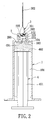
- Referring to Figs. 1 and 2, a conventional syringe includes a
syringe barrel 1, aretaining seat 2, aneedle unit 3 connected threadably to the retainingseat 2, and aplunger 4. Thebarrel 1 has aninterior chamber 101, a front end opening 102, and ashoulder 103. Theretaining seat 2 is tubular, and includes anoutward flange 201 extending radially and outwardly from a rear end of acylindrical portion 202, an O-ring 203 sleeved on thecylindrical portion 202, and aninward flange 204 extending radially and inwardly from thecylindrical portion 202 and disposed immediately in front of theoutward flange 201. Thecylindrical portion 202 has an internally threadedfront end 205. Theneedle unit 3 includes an externally threadedneedle seat 301 engaging threadably thefront end 205 of thecylindrical portion 202 of theretaining seat 2, and aneedle body 302. Theplunger 4 is movable within thebarrel 1 between a front limit position and a rear limit position, and has anactuation rod portion 401, apiston 402 disposed movably and sealingly within theinterior chamber 101 in thebarrel 1, and a mushroom-shaped tongue 403 extending forwardly from thepiston 402. When theplunger 4 is moved to the front limit position, thetongue 403 engages a hole defined by theinward flange 204 of the retainingseat 2 so as to permit synchronous movement of the retainingseat 2, theneedle unit 3, and theplunger 4 when theplunger 4 moves back to the rear limit position, thereby retracting theneedle body 32 into thebarrel 1. Thetongue 403 has a head that is formed with aslot 404 so as to permit the head to move into theneedle seat 301 through the hole defined by theinward flange 103 and so as to prevent removal of the head from theneedle seat 301 through the hole defined by theinward flange 103. As such, after use, theneedle unit 3 can be brought into thebarrel 1 by moving theplunger 4 from the front limit position to the rear limit position so as to prevent theneedle body 32 from hurting the user. The aforesaid conventional syringe suffers from the following disadvantages: - 1. The retaining
seat 2 and the O-ring 203 are two separate members, which are manufactured by using two different machines, thereby increasing the manufacturing costs. - 2. Because the size of the O-
ring 203 is relatively small, it is difficult to sleeve the O-ring 203 manually around the retainingseat 2 so that the O-ring 203 is normally mounted on retainingseat 2 in an automated manner. However, the O-ring 203 may escape from its predetermined position during mechanical assembly in view of its elasticity. In the event that the escaped O-ring 203 moves into a space between two moving parts of a machine, the mounting operation may be interrupted for servicing of the machine. - 3. During assembly, it is necessary to rotate the retaining
seat 2 and theneedle unit 3 relative to each other, thereby resulting in a troublesome process. -
- Therefore, the object of this invention is to provide a syringe with a retaining seat unit, which includes an annular rib that is formed integrally with a retaining element and that serves as an O-ring so as to overcome the aforesaid disadvantages associated with the prior art.
- According to this invention, a syringe includes a syringe barrel, a retaining seat unit, a needle unit, and a plunger. The retaining seat unit has a rigid tubular main body that is disposed within the barrel, and a tubular retaining element that is fixed within the main body and that has an annular outer surface, which is formed with an integral rib. The retaining seat unit has a maximum outer diameter at the annular rib so that the annular rib serves as an O-ring.
- These and other features and advantages of this invention will become apparent in the following detailed description of the preferred embodiments of this invention, with reference to the accompanying drawings, in which:
- Fig. 1 is an exploded perspective view of a conventional syringe;
- Fig. 2 is a longitudinal sectional view of the conventional syringe;
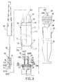
- Fig. 3 is an exploded sectional view of the first preferred embodiment of a syringe according to this invention;
- Fig. 4 is a sectional view of a retaining seat unit of the first preferred embodiment, taken along Line 4-4 in Fig. 3;
- Fig. 5 is a longitudinal sectional view of the first preferred embodiment;
- Fig. 6 is a longitudinal sectional view of the first preferred embodiment, illustrating a front limit position of a plunger;
- Fig. 7 is a longitudinal sectional view of the first preferred embodiment, illustrating a rear limit position of the plunger, which is broken at a neck portion;
- Fig. 8 is a fragmentary longitudinal sectional view of the second preferred embodiment of a syringe according to this invention;
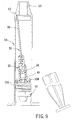
- Fig. 9 is a longitudinal sectional view of the second preferred embodiment, illustrating how a needle body is retracted into a syringe barrel;
- Fig. 10 is a fragmentary longitudinal sectional view of the third preferred embodiment of a syringe according to this invention; and
- Fig. 11 is a fragmentary longitudinal sectional view of the fourth preferred embodiment of a syringe according to this invention.
-
- Before the present invention is described in greater detail in connection with the preferred embodiments, it should be noted that similar elements and structures are designated by like reference numerals throughout the entire disclosure.
- Referring to Figs. 3, 4, and 5, the first preferred embodiment of a syringe according to this invention is shown to include a
syringe barrel 10, a retainingseat unit 20 disposed in thebarrel 10 , aneedle unit 30 connected fixedly to the retainingseat unit 20, and aplunger 40 disposed movably within thebarrel 10. - The
barrel 10 has a central axis (L), abarrel body 11 with aninterior chamber 111, a frontwardly convergingfront end portion 12 with a uniform-diameter front end opening 121 formed therethrough, ashoulder 13 formed between thefront end opening 121 and theinterior chamber 111, and anannular groove 13 formed in an inner surface of a front end of thebarrel body 11. Thebarrel body 11 has a rear end that is formed with an integralinward flange 15 which extends radially and inwardly therefrom and which defines arear clamping hole 16. - The retaining
seat unit 20 is disposed in a front end of thebarrel 10, and includes a unitary, rigid tubularmain body 23 made of a plastic material and disposed within thebarrel 10, and a unitary, tubular retainingelement 24 made of rubber and fixed within themain body 23. Themain body 23 has a rear end that is formed with an integraloutward flange 231, a frontcylindrical portion 232, and four projections 236 (see Fig. 4) extending rearwardly from theoutward flange 231. Theoutward flange 231 of themain body 23 abuts against theshoulder 13 of thebarrel 10. The retainingelement 24 has a rear end that is formed with anoutward flange 241 and a rearinward flange 242, and a front end, which is disposed within themain body 23, which extends into the front end opening 121 in thebarrel 10, and which is formed with a frontinward flange 243. Theinward flanges barrel 10. The retainingelement 24 is molded on themain body 23 so that theoutward flange 241 of the retainingelement 24 is secured to theprojections 236 of themain body 23. As such, theoutward flange 241 of the retainingelement 24 abuts against and is connected fixedly to theoutward flange 231 of themain body 23. An annular rib (23R) is formed on an annular outer surface of theoutward flange 241 of the retainingelement 24, and has an outer diameter (D) that is greater than the outer diameter (d) of theoutward flanges main body 23 and the retainingelement 24, as shown in Fig. 3. That is to say, the retainingseat unit 20 has a maximum outer diameter at the annular rib (23R). The annular rib (23R) engages theannular groove 14 in thebarrel 10 so as to anchor the retainingseat unit 20 within thebarrel 10, and serves as an O-ring so as to establish a liquid-tight seal between thebarrel 10 and the retainingseat unit 20. - The
needle unit 30 includes aneedle seat 31, aneedle body 32 inserted into and fixed within theneedle seat 31 by an adhesive material (H) , and acover body 33 sleeved on theneedle seat 31 and theneedle body 32. Theneedle seat 31 has a mushroom-shapedtongue 311 at a rear end, and anoutward flange 312 abutting against a rear end of thecover body 33. Thetongue 311 has a uniform-diameter front tongue portion (311F) extending through the front clamping hole (243H), and a large-diameter rear tongue portion (311R) connected to a rear end of the front tongue portion (311F) and having a maximum diameter greater than the diameter of the front tongue portion (311F). Therear tongue portion 311R abuts against a rear end of the frontinward flange 243 of the retainingseat unit 24 so as to retain theneedle seat 31 on the retainingseat unit 20. The rear tongue portion (311R) of thetongue 311 of theneedle seat 31 has a frusto-conical rear end (311T), and the front clamping hole (243H) in the retainingelement 24 has a frusto-conical front end (243T) so as to guide thetongue 311 of theneedle seat 31 to engage the front clamping hole (243H) in the retainingelement 24. - The
plunger 40 is disposed within thebarrel 10, is located behind the retainingseat unit 20, and includes anactuation rod portion 41, apiston 42, a mushroom-shapedtongue 43, acircular abutment plate 44, and aneck portion 45 having two ends connected respectively and integrally with theactuation rod portion 41 and theabutment plate 44. Theactuation rod portion 41 proj ects rearwardly from thebarrel 10. Thepiston 42 is disposed movably and sealingly within thebarrel 10, and is connected fixedly to and is disposed in front of theabutment plate 44. Thetongue 43 is connected fixedly to and extends forwardly from thepiston 42. Thetongue 43 has a conical front head portion (43F) and a uniform-diameter rear neck portion (43R) that is connected to a rear end of the front head portion (43F). The front head portion (43F) has a maximum diameter greater than the diameter of the rear neck portion (43R), and a rear end surface that is perpendicular to the central axis (L) of thebarrel 10. The rear clamping hole (242H) in the retainingelement 242 has a frusto-conical rear end (242T) so as to guide thetongue 43 to engage the rear clamping hole (242H). Theneck portion 45 has a diameter smaller than those of theabutment plate 44 and theactuation rod portion 41. - The
inward flange 15 of thebarrel 10 has an inclined rear end 151 (see Fig. 3) so that thepiston 42 and theabutment plate 44 of theplunger 40 can be forced to move into thebarrel 10. - After use, the
plunger 40 can be moved within thebarrel 10 to a front limit position shown in Fig. 6, where the rear neck portion (43R) of thetongue 43 extends through the rear clamping hole (242H) and where the front head portion (43F) of thetongue 43 abuts against a front end of theinward flange 242 of theretaining element 24 so as to retain the retainingseat unit 20 on thetongue 43, thereby permitting synchronous movement of theplunger 40 and the retainingseat unit 20 when theplunger 40 moves rearward within thebarrel 10 so as to retract theneedle body 32 into thebarrel 10. Subsequently, theplunger 40 is moved within thebarrel 10 to a rear limit position shown in Fig. 7, where theabutment plate 44 abuts against a front end of theinward flange 15, where theneedle body 32 is retracted into thebarrel 10, and where a force can be applied to theactuation rod portion 41 in a transverse direction (F) relative to theplunger 40 so as to break theplunger 40 at theneck portion 45. - Some of the advantages of the syringe of this invention can be summarized as follows:
- 1. Because the annular rib (23R) is formed integrally with
the retaining
element 24, it is not necessary to provide an O-ring around the retainingseat unit 20. As such, the drawbacks associated with the presence of the O-ring in the conventional syringe are eliminated. - 2. The
needle unit 3 0 can be mounted easily on the retainingseat unit 20. -
- Fig. 8 shows the second preferred embodiment of a syringe according to this invention. Unlike the first preferred embodiment, the central axis (L') of the rear clamping hole (242H) is inclined relative to that of the
barrel 10. The rearinward flange 242 of the retainingelement 24 has a front end surface (242F) that is perpendicular to the central axis (L') of the rear clamping hole (242H). Referring to Fig. 9, when theneck portion 45 of theplunger 40 is broken, theneedle body 32 turns to an inclined position, where theneedle body 32 is inclined relative to the central axis of thebarrel 10. As such, theneedle body 32 is prevented from moving back into the front end opening 121 in thebarrel 10. - Fig. 10 shows the third preferred embodiment of a syringe according to this invention. Unlike the first preferred embodiment, the
needle seat 31 is formed integrally with themain body 23 of the retainingseat unit 20. - The first preferred embodiment can be modified to have the structural changes of the second and third preferred embodiments, as shown in the embodiment of Fig. 11.
Claims (11)
- A syringe including a syringe barrel (10) , a retaining seat unit (20) disposed in a front end of the barrel (10), a needle unit (30) connected fixedly to the retaining seat unit (20) , and a plunger (40) disposed movably within the barrel (10) and behind the retaining seat unit (20), characterized in that the retaining seat unit (20) includes:fixed within the main body (23) , the retaining element (24) having an annular outer surface that is formed with an annular rib (23R) , an assembly of the main body (23) and the retaining element (24) having a maximum outer diameter at the annular rib (23R) so that the annular rib (23R) can contact an inner surface of the barrel (10), thereby establishing a liquid-tight seal between the barrel (10) and the assembly of the main body (23) and the retaining element (24).a rigid tubular main body (23) disposed in the front end of the barrel (10); anda tubular retaining element (24)
- The syringe as claimed in Claim 1, further characterized in that the inner surface of the barrel (10) is formed with an annular groove (14), the annular rib (23R) of the retaining element (23) engaging the annular groove (14) so as to anchor the retaining seat unit (20) within the barrel (10).
- The syringe as claimed in Claim 1, characterized by:the barrel (10) having a front end opening (121);the retaining element (24) having a front end that extends into the opening (121) in the barrel (10) and that is formed with an integral front inward flange (243) which extends radially and inwardly therefrom and which defines a front clamping hole (243H); andthe needle unit (30) including a needle seat (31) and a needle body (32) connected fixedly to the needle seat (31), the needle seat (31) being formed with an integral mushroom-shaped tongue (311) which has a uniform-diameter front tongue portion (311F) extending through the front clamping hole (243H) in the retaining seat unit (20), and a rear tongue portion (311R) connected to a rear end of the front tongue portion (311F) and having a maximum diameter greater than the diameter of the front tongue portion (311F), the rear tongue portion (311R) abutting against a rear end of the front inward flange (243) of the retaining seat unit (24) so as to retain the needle seat (31) on the retaining seat unit (20).
- The syringe as claimed in Claim 3, further characterized in that the rear tongue portion (311R) of the tongue (311) of the needle seat (31) has a frusto-conical rear end (311T), and the front clamping hole (243H) in the retaining element (24) has a frusto-conical front end (243T) so as to guide the tongue (311) of the needle seat (31) to engage the front clamping hole (243H) in the retaining element (24).
- The syringe as claimed in Claim 1, further characterized in that the needle unit (30) includes a needle seat (31) formed integrally with a front end of the main body (23) of the retaining seat unit (3) , and a needle body (32) connected fixedly to the needle seat (31).
- The syringe as claimed in Claim 1, further characterized in that the main body (23) of the retaining seat unit (20) has a rear end that is formed with an outward flange (231) extending radially and outwardly therefrom, and the retaining element (24) of the retaining seat unit (20) has a rear end that is formed with an outward flange (241) which abuts against and which is secured to the outward flange (231) of the main body (23) , the annular rib (23R) being formed on the outward flange (241) of the retaining element (24).
- The syringe as claimed in Claim 6, further characterized in that the outward flange (231) of the main body (23) is formed with a plurality of projections (236) extending rearwardly therefrom, the outward flange (241) of the retaining element (24) being molded on the projections (236) so as to connect the retaining element (24) fixedly to the main body (23).
- The syringe as claimed in Claim 1, further characterized in that the retaining element (24) of the retaining seat unit (20) has a rear end that is formed with an integral inward flange (242) that defines a rear clamping hole (242H) , the plunger (40) having a front end that is formed with an integral mushroom-shaped tongue (43) which has a front head portion (43F) and a uniform-diameter rear neck portion (43R) that is connected to a rear end of the front head portion (43F) , the front head portion (43F) having a maximum diameter greater than the diameter of the rearneckportion (43R), the plunger (40) being movable within the barrel (10) between a rear limit position and a front limit posit ion, where the rear neck portion (43R) of the tongue (43) extends through the rear clamping hole (242H) and where the front head portion (43F) of the tongue (43) abuts against a front end of the inward flange (242) of the retaining element (24) so as to retain the retaining seat unit (20) on the tongue (43), thereby permitting synchronous movement of the plunger (40) and the retaining seat unit (20) when the plunger (40) moves rearward within the barrel (10) so as to retract the needle body (32) into the barrel (10).
- The syringe as claimed in Claim 8, further characterized in that the front head portion (43F) of the tongue (43) of the plunger (40) is conical, and the rear clamping hole (242H) in the retaining element (242) has a frusto-conical rear end (242T) so as to guide the tongue (43) to engage the rear clamping hole (242H).
- The syringe as claimed in Claim 8, further characterized in that the barrel (10) has a rear end that is formed with an integral inward flange (15) that defines a rear end opening (16) of the barrel (10), the plunger (40) further having:an actuation rod portion (41) projecting rearwardly from the barrel (10);a piston (42) disposed between and connected fixedly to the tongue (43) and the actuation rod portion (41) and disposed movably and sealingly within the barrel (10);an abutment plate (44) disposed between and connected fixedly to the piston (42) and the actuation rod portion (41), the abutment plate (44) abutting against a front end of the inward flange (15) of the barrel (10) when the plunger (40) is disposed at the rear limit position; anda neck portion (45) having two ends connected respectively and fixedly to the abutment plate (44) and the actuation rod portion (41), and a diameter smaller than those of the abutment plate (44) and the actuation rod portion (41), the neck portion (45) extending through the rear end opening (16) in the barrel (10) when the plunger (40) is disposed at the rear limit position so as to permit the plunger (40) to be broken at the neck portion (45) by applying a force to the actuation rod portion (41) in a transverse direction relative to the plunger (40).
- The syringe as claimed in Claim 10, further characterized in that the rear clamping hole (242H) in the retaining element (23) has a central axis (L') that is inclined relative to a central axis (L) of the barrel (10) so that the needle body (32) turns within the barrel (10) toaninclinedposition, where the needle body (32) is inclined relative to the central axis (L) of the barrel (10), when the neck portion (45) of the plunger (40) is broken.
Priority Applications (11)
| Application Number | Priority Date | Filing Date | Title |
|---|---|---|---|
| EP03102725A EP1514566B1 (en) | 2003-09-09 | 2003-09-09 | Syringe including a retaining element with an integral annular rib |
| DE60322700T DE60322700D1 (en) | 2003-09-09 | 2003-09-09 | Syringe with an integral annular rib holding member |
| AT03102725T ATE403457T1 (en) | 2003-09-09 | 2003-09-09 | SYRINGE HAVING A HOLDING ELEMENT HAVING AN INTEGRAL ANNUAL RIB |
| RU2006106780/14A RU2329067C2 (en) | 2003-09-09 | 2004-09-09 | Safe syringe |
| KR1020067006787A KR20060128854A (en) | 2003-09-09 | 2004-09-09 | Safety syringe |
| AU2004281092A AU2004281092A1 (en) | 2003-09-09 | 2004-09-09 | Safety syringe |
| MXPA06002688A MXPA06002688A (en) | 2003-09-09 | 2004-09-09 | Safety syringe. |
| JP2006525607A JP2007504868A (en) | 2003-09-09 | 2004-09-09 | Safety syringe |
| BRPI0413773-6A BRPI0413773A (en) | 2003-09-09 | 2004-09-09 | syringe with safety device |
| PCT/CN2004/001033 WO2005037351A1 (en) | 2003-09-09 | 2004-09-09 | Safety syringe |
| ZA200601965A ZA200601965B (en) | 2003-09-09 | 2006-03-08 | Safety syringe |
Applications Claiming Priority (1)
| Application Number | Priority Date | Filing Date | Title |
|---|---|---|---|
| EP03102725A EP1514566B1 (en) | 2003-09-09 | 2003-09-09 | Syringe including a retaining element with an integral annular rib |
Publications (2)
| Publication Number | Publication Date |
|---|---|
| EP1514566A1 true EP1514566A1 (en) | 2005-03-16 |
| EP1514566B1 EP1514566B1 (en) | 2008-08-06 |
Family
ID=34130318
Family Applications (1)
| Application Number | Title | Priority Date | Filing Date |
|---|---|---|---|
| EP03102725A Expired - Lifetime EP1514566B1 (en) | 2003-09-09 | 2003-09-09 | Syringe including a retaining element with an integral annular rib |
Country Status (4)
| Country | Link |
|---|---|
| EP (1) | EP1514566B1 (en) |
| AT (1) | ATE403457T1 (en) |
| DE (1) | DE60322700D1 (en) |
| ZA (1) | ZA200601965B (en) |
Cited By (13)
| Publication number | Priority date | Publication date | Assignee | Title |
|---|---|---|---|---|
| EP1716881A1 (en) * | 2005-11-29 | 2006-11-02 | Xiang Guang International Co., Ltd. | Safety syringe |
| EP1754499A1 (en) * | 2005-08-19 | 2007-02-21 | Wei-Shui Wu | Safety hypodermic syringe with retractable needle carrier |
| EP1772163A1 (en) * | 2006-02-20 | 2007-04-11 | HSU, Chih-Kuang | Safety syringe |
| WO2007047403A1 (en) * | 2005-10-13 | 2007-04-26 | Becton, Dickinson And Company | Disposable needle and hub assembly |
| JP2007117775A (en) * | 2005-07-08 | 2007-05-17 | Xiang Guang Internatl Co Ltd | Safety syringe |
| GB2434538A (en) * | 2006-01-20 | 2007-08-01 | Fen-Fang Chang | A safety syringe |
| WO2007112470A1 (en) | 2006-04-06 | 2007-10-11 | Pharma Consult Ges.M.B.H & Co Nfg Kg | Injection syringe |
| WO2009097634A1 (en) * | 2008-02-07 | 2009-08-13 | Brigitte Pickhard | Injection syringe |
| EP2086616A4 (en) * | 2006-11-28 | 2012-09-26 | Morgan Meditech Inc | Retractable syringe |
| WO2013008094A3 (en) * | 2011-06-03 | 2013-08-01 | Jan Kavalirek | Syringe needle catching device and safety syringe with this device |
| RU2520818C2 (en) * | 2009-04-14 | 2014-06-27 | Бомтек Электроникс Ко., Лтд. | Needle unit and sprayer for subcutaneous liquid injection using same |
| WO2015070524A1 (en) * | 2013-10-18 | 2015-05-21 | 王祖扬 | Pulled-back replaceable-needle safe self-destroying syringe |
| AU2014218378B2 (en) * | 2009-12-22 | 2015-12-03 | Unitract Syringe Pty Ltd | Retractable syringe with improved delivery efficiency and locking system |
Families Citing this family (2)
| Publication number | Priority date | Publication date | Assignee | Title |
|---|---|---|---|---|
| CN102271730B (en) | 2008-11-26 | 2014-08-27 | 贝克顿·迪金森公司 | Single-use self-disabling syringes |
| AU2010336003B2 (en) | 2009-12-22 | 2014-07-03 | Unitract Syringe Pty Ltd | Retractable syringe with improved delivery efficiency and locking system |
Citations (4)
| Publication number | Priority date | Publication date | Assignee | Title |
|---|---|---|---|---|
| US5968019A (en) * | 1998-07-14 | 1999-10-19 | Tun Huang International Development And Investment Co., Ltd. | Safety syringe |
| US6402721B1 (en) * | 2000-06-30 | 2002-06-11 | Cheng-Chi Lo | Safety hypodermic syringe with detachable plunger |
| US6423033B1 (en) * | 2001-03-02 | 2002-07-23 | Jin-Chou Tsai | Safety hypodermic syringe |
| US20030060775A1 (en) * | 2001-09-27 | 2003-03-27 | Mei-Ching Shyu | Disposable safety syringe |
-
2003
- 2003-09-09 DE DE60322700T patent/DE60322700D1/en not_active Expired - Lifetime
- 2003-09-09 AT AT03102725T patent/ATE403457T1/en not_active IP Right Cessation
- 2003-09-09 EP EP03102725A patent/EP1514566B1/en not_active Expired - Lifetime
-
2006
- 2006-03-08 ZA ZA200601965A patent/ZA200601965B/en unknown
Patent Citations (4)
| Publication number | Priority date | Publication date | Assignee | Title |
|---|---|---|---|---|
| US5968019A (en) * | 1998-07-14 | 1999-10-19 | Tun Huang International Development And Investment Co., Ltd. | Safety syringe |
| US6402721B1 (en) * | 2000-06-30 | 2002-06-11 | Cheng-Chi Lo | Safety hypodermic syringe with detachable plunger |
| US6423033B1 (en) * | 2001-03-02 | 2002-07-23 | Jin-Chou Tsai | Safety hypodermic syringe |
| US20030060775A1 (en) * | 2001-09-27 | 2003-03-27 | Mei-Ching Shyu | Disposable safety syringe |
Cited By (20)
| Publication number | Priority date | Publication date | Assignee | Title |
|---|---|---|---|---|
| JP2007117775A (en) * | 2005-07-08 | 2007-05-17 | Xiang Guang Internatl Co Ltd | Safety syringe |
| EP1754499A1 (en) * | 2005-08-19 | 2007-02-21 | Wei-Shui Wu | Safety hypodermic syringe with retractable needle carrier |
| WO2007047403A1 (en) * | 2005-10-13 | 2007-04-26 | Becton, Dickinson And Company | Disposable needle and hub assembly |
| EP1716881A1 (en) * | 2005-11-29 | 2006-11-02 | Xiang Guang International Co., Ltd. | Safety syringe |
| GB2434538B (en) * | 2006-01-20 | 2010-12-29 | Fen-Fang Chang | Safety syringe |
| GB2434538A (en) * | 2006-01-20 | 2007-08-01 | Fen-Fang Chang | A safety syringe |
| EP1772163A1 (en) * | 2006-02-20 | 2007-04-11 | HSU, Chih-Kuang | Safety syringe |
| US8105293B2 (en) | 2006-04-06 | 2012-01-31 | Pharma Consult Ges.M.B.H & Co Nfg Kg | Injection syringe |
| WO2007112470A1 (en) | 2006-04-06 | 2007-10-11 | Pharma Consult Ges.M.B.H & Co Nfg Kg | Injection syringe |
| EP2086616A4 (en) * | 2006-11-28 | 2012-09-26 | Morgan Meditech Inc | Retractable syringe |
| WO2009097634A1 (en) * | 2008-02-07 | 2009-08-13 | Brigitte Pickhard | Injection syringe |
| US20110046561A1 (en) * | 2008-02-07 | 2011-02-24 | Brigitte Pickhard | Injection syringe |
| RU2465021C2 (en) * | 2008-02-07 | 2012-10-27 | Фарма Консалт Гез.М.Б.Х. Унд Ко Нфг Кг | Injection syringe |
| CN101939038B (en) * | 2008-02-07 | 2013-03-06 | 制药咨询有限及两合继承公司 | syringe |
| AU2009212083B2 (en) * | 2008-02-07 | 2013-07-11 | Pharma Consult Ges.M.B.H. | Injection syringe |
| US8728042B2 (en) | 2008-02-07 | 2014-05-20 | Pharma Consult Ges.M.B.H. | Injection syringe |
| RU2520818C2 (en) * | 2009-04-14 | 2014-06-27 | Бомтек Электроникс Ко., Лтд. | Needle unit and sprayer for subcutaneous liquid injection using same |
| AU2014218378B2 (en) * | 2009-12-22 | 2015-12-03 | Unitract Syringe Pty Ltd | Retractable syringe with improved delivery efficiency and locking system |
| WO2013008094A3 (en) * | 2011-06-03 | 2013-08-01 | Jan Kavalirek | Syringe needle catching device and safety syringe with this device |
| WO2015070524A1 (en) * | 2013-10-18 | 2015-05-21 | 王祖扬 | Pulled-back replaceable-needle safe self-destroying syringe |
Also Published As
| Publication number | Publication date |
|---|---|
| ATE403457T1 (en) | 2008-08-15 |
| ZA200601965B (en) | 2007-12-27 |
| DE60322700D1 (en) | 2008-09-18 |
| EP1514566B1 (en) | 2008-08-06 |
Similar Documents
| Publication | Publication Date | Title |
|---|---|---|
| EP1514566B1 (en) | Syringe including a retaining element with an integral annular rib | |
| US8181489B2 (en) | Knitting tool | |
| US20160311091A1 (en) | Tool coupler | |
| US20050203458A1 (en) | Safe retractable type syringe | |
| CN109310074B (en) | Fishing reel seat, fishing rod and lower component of fishing reel seat | |
| US6402721B1 (en) | Safety hypodermic syringe with detachable plunger | |
| US6745652B2 (en) | Tool combining rod | |
| CN114098919A (en) | Implant injector | |
| EP0210280A1 (en) | Eversharp pencil | |
| US20080009795A1 (en) | Plunger of a syringe | |
| US20060229554A1 (en) | Mechanism for tilting retractable needle | |
| US20200361230A1 (en) | Writing instrument and method for manufacturing writing instrument | |
| US5519927A (en) | Rivet setting tool | |
| CN212905658U (en) | Focusing barrel | |
| US4204299A (en) | Replaceable tip for desoldering tools | |
| JP4642281B2 (en) | mechanical pencil | |
| US3450482A (en) | Pencil lead holder with fixed length feed | |
| US20190375230A1 (en) | Mechanical pencil | |
| US20030206780A1 (en) | Spindle assembly for a machine tool | |
| CA1255629A (en) | Mechanical pencil | |
| JP2020104414A (en) | Lead feeding device | |
| CN112622186A (en) | A ejecting structure and injection mould for injection mold | |
| JP6816900B2 (en) | Manufacturing method of lead for mechanical pencil | |
| JP7702510B2 (en) | Ballpoint pen | |
| KR101764326B1 (en) | Manually retractable type safety syringe |
Legal Events
| Date | Code | Title | Description |
|---|---|---|---|
| PUAI | Public reference made under article 153(3) epc to a published international application that has entered the european phase |
Free format text: ORIGINAL CODE: 0009012 |
|
| 17P | Request for examination filed |
Effective date: 20040615 |
|
| AK | Designated contracting states |
Kind code of ref document: A1 Designated state(s): AT BE BG CH CY CZ DE DK EE ES FI FR GB GR HU IE IT LI LU MC NL PT RO SE SI SK TR |
|
| AX | Request for extension of the european patent |
Extension state: AL LT LV MK |
|
| AKX | Designation fees paid |
Designated state(s): AT BE BG CH CY CZ DE DK EE ES FI FR GB GR HU IE IT LI LU MC NL PT RO SE SI SK TR |
|
| 17Q | First examination report despatched |
Effective date: 20061027 |
|
| 17Q | First examination report despatched |
Effective date: 20061027 |
|
| GRAP | Despatch of communication of intention to grant a patent |
Free format text: ORIGINAL CODE: EPIDOSNIGR1 |
|
| GRAS | Grant fee paid |
Free format text: ORIGINAL CODE: EPIDOSNIGR3 |
|
| GRAA | (expected) grant |
Free format text: ORIGINAL CODE: 0009210 |
|
| AK | Designated contracting states |
Kind code of ref document: B1 Designated state(s): AT BE BG CH CY CZ DE DK EE ES FI FR GB GR HU IE IT LI LU MC NL PT RO SE SI SK TR |
|
| REG | Reference to a national code |
Ref country code: GB Ref legal event code: FG4D |
|
| REG | Reference to a national code |
Ref country code: CH Ref legal event code: EP |
|
| REG | Reference to a national code |
Ref country code: IE Ref legal event code: FG4D |
|
| REF | Corresponds to: |
Ref document number: 60322700 Country of ref document: DE Date of ref document: 20080918 Kind code of ref document: P |
|
| PG25 | Lapsed in a contracting state [announced via postgrant information from national office to epo] |
Ref country code: NL Free format text: LAPSE BECAUSE OF FAILURE TO SUBMIT A TRANSLATION OF THE DESCRIPTION OR TO PAY THE FEE WITHIN THE PRESCRIBED TIME-LIMIT Effective date: 20080806 Ref country code: ES Free format text: LAPSE BECAUSE OF FAILURE TO SUBMIT A TRANSLATION OF THE DESCRIPTION OR TO PAY THE FEE WITHIN THE PRESCRIBED TIME-LIMIT Effective date: 20081117 |
|
| PG25 | Lapsed in a contracting state [announced via postgrant information from national office to epo] |
Ref country code: FI Free format text: LAPSE BECAUSE OF FAILURE TO SUBMIT A TRANSLATION OF THE DESCRIPTION OR TO PAY THE FEE WITHIN THE PRESCRIBED TIME-LIMIT Effective date: 20080806 Ref country code: AT Free format text: LAPSE BECAUSE OF FAILURE TO SUBMIT A TRANSLATION OF THE DESCRIPTION OR TO PAY THE FEE WITHIN THE PRESCRIBED TIME-LIMIT Effective date: 20080806 Ref country code: SI Free format text: LAPSE BECAUSE OF FAILURE TO SUBMIT A TRANSLATION OF THE DESCRIPTION OR TO PAY THE FEE WITHIN THE PRESCRIBED TIME-LIMIT Effective date: 20080806 |
|
| PG25 | Lapsed in a contracting state [announced via postgrant information from national office to epo] |
Ref country code: BE Free format text: LAPSE BECAUSE OF FAILURE TO SUBMIT A TRANSLATION OF THE DESCRIPTION OR TO PAY THE FEE WITHIN THE PRESCRIBED TIME-LIMIT Effective date: 20080806 |
|
| PG25 | Lapsed in a contracting state [announced via postgrant information from national office to epo] |
Ref country code: DK Free format text: LAPSE BECAUSE OF FAILURE TO SUBMIT A TRANSLATION OF THE DESCRIPTION OR TO PAY THE FEE WITHIN THE PRESCRIBED TIME-LIMIT Effective date: 20080806 Ref country code: BG Free format text: LAPSE BECAUSE OF FAILURE TO SUBMIT A TRANSLATION OF THE DESCRIPTION OR TO PAY THE FEE WITHIN THE PRESCRIBED TIME-LIMIT Effective date: 20081106 Ref country code: MC Free format text: LAPSE BECAUSE OF NON-PAYMENT OF DUE FEES Effective date: 20080930 |
|
| REG | Reference to a national code |
Ref country code: CH Ref legal event code: PL |
|
| PG25 | Lapsed in a contracting state [announced via postgrant information from national office to epo] |
Ref country code: SK Free format text: LAPSE BECAUSE OF FAILURE TO SUBMIT A TRANSLATION OF THE DESCRIPTION OR TO PAY THE FEE WITHIN THE PRESCRIBED TIME-LIMIT Effective date: 20080806 Ref country code: PT Free format text: LAPSE BECAUSE OF FAILURE TO SUBMIT A TRANSLATION OF THE DESCRIPTION OR TO PAY THE FEE WITHIN THE PRESCRIBED TIME-LIMIT Effective date: 20090106 Ref country code: CZ Free format text: LAPSE BECAUSE OF FAILURE TO SUBMIT A TRANSLATION OF THE DESCRIPTION OR TO PAY THE FEE WITHIN THE PRESCRIBED TIME-LIMIT Effective date: 20080806 Ref country code: RO Free format text: LAPSE BECAUSE OF FAILURE TO SUBMIT A TRANSLATION OF THE DESCRIPTION OR TO PAY THE FEE WITHIN THE PRESCRIBED TIME-LIMIT Effective date: 20080806 |
|
| PLBE | No opposition filed within time limit |
Free format text: ORIGINAL CODE: 0009261 |
|
| STAA | Information on the status of an ep patent application or granted ep patent |
Free format text: STATUS: NO OPPOSITION FILED WITHIN TIME LIMIT |
|
| 26N | No opposition filed |
Effective date: 20090507 |
|
| PG25 | Lapsed in a contracting state [announced via postgrant information from national office to epo] |
Ref country code: IE Free format text: LAPSE BECAUSE OF NON-PAYMENT OF DUE FEES Effective date: 20080909 Ref country code: EE Free format text: LAPSE BECAUSE OF FAILURE TO SUBMIT A TRANSLATION OF THE DESCRIPTION OR TO PAY THE FEE WITHIN THE PRESCRIBED TIME-LIMIT Effective date: 20080806 |
|
| PG25 | Lapsed in a contracting state [announced via postgrant information from national office to epo] |
Ref country code: IT Free format text: LAPSE BECAUSE OF FAILURE TO SUBMIT A TRANSLATION OF THE DESCRIPTION OR TO PAY THE FEE WITHIN THE PRESCRIBED TIME-LIMIT Effective date: 20080806 |
|
| PG25 | Lapsed in a contracting state [announced via postgrant information from national office to epo] |
Ref country code: LI Free format text: LAPSE BECAUSE OF NON-PAYMENT OF DUE FEES Effective date: 20080930 Ref country code: CH Free format text: LAPSE BECAUSE OF NON-PAYMENT OF DUE FEES Effective date: 20080930 |
|
| PGFP | Annual fee paid to national office [announced via postgrant information from national office to epo] |
Ref country code: GB Payment date: 20090929 Year of fee payment: 7 |
|
| PG25 | Lapsed in a contracting state [announced via postgrant information from national office to epo] |
Ref country code: SE Free format text: LAPSE BECAUSE OF FAILURE TO SUBMIT A TRANSLATION OF THE DESCRIPTION OR TO PAY THE FEE WITHIN THE PRESCRIBED TIME-LIMIT Effective date: 20081106 |
|
| PGFP | Annual fee paid to national office [announced via postgrant information from national office to epo] |
Ref country code: DE Payment date: 20091125 Year of fee payment: 7 |
|
| PGFP | Annual fee paid to national office [announced via postgrant information from national office to epo] |
Ref country code: FR Payment date: 20091015 Year of fee payment: 7 |
|
| PG25 | Lapsed in a contracting state [announced via postgrant information from national office to epo] |
Ref country code: CY Free format text: LAPSE BECAUSE OF FAILURE TO SUBMIT A TRANSLATION OF THE DESCRIPTION OR TO PAY THE FEE WITHIN THE PRESCRIBED TIME-LIMIT Effective date: 20080806 Ref country code: LU Free format text: LAPSE BECAUSE OF NON-PAYMENT OF DUE FEES Effective date: 20080909 Ref country code: HU Free format text: LAPSE BECAUSE OF FAILURE TO SUBMIT A TRANSLATION OF THE DESCRIPTION OR TO PAY THE FEE WITHIN THE PRESCRIBED TIME-LIMIT Effective date: 20090207 |
|
| PG25 | Lapsed in a contracting state [announced via postgrant information from national office to epo] |
Ref country code: TR Free format text: LAPSE BECAUSE OF FAILURE TO SUBMIT A TRANSLATION OF THE DESCRIPTION OR TO PAY THE FEE WITHIN THE PRESCRIBED TIME-LIMIT Effective date: 20080806 |
|
| PG25 | Lapsed in a contracting state [announced via postgrant information from national office to epo] |
Ref country code: GR Free format text: LAPSE BECAUSE OF FAILURE TO SUBMIT A TRANSLATION OF THE DESCRIPTION OR TO PAY THE FEE WITHIN THE PRESCRIBED TIME-LIMIT Effective date: 20081107 |
|
| GBPC | Gb: european patent ceased through non-payment of renewal fee |
Effective date: 20100909 |
|
| REG | Reference to a national code |
Ref country code: FR Ref legal event code: ST Effective date: 20110531 |
|
| REG | Reference to a national code |
Ref country code: DE Ref legal event code: R119 Ref document number: 60322700 Country of ref document: DE Effective date: 20110401 |
|
| PG25 | Lapsed in a contracting state [announced via postgrant information from national office to epo] |
Ref country code: DE Free format text: LAPSE BECAUSE OF NON-PAYMENT OF DUE FEES Effective date: 20110401 Ref country code: FR Free format text: LAPSE BECAUSE OF NON-PAYMENT OF DUE FEES Effective date: 20100930 |
|
| PG25 | Lapsed in a contracting state [announced via postgrant information from national office to epo] |
Ref country code: GB Free format text: LAPSE BECAUSE OF NON-PAYMENT OF DUE FEES Effective date: 20100909 |