EP1514057B1 - Centrale a charbon - Google Patents
Centrale a charbon Download PDFInfo
- Publication number
- EP1514057B1 EP1514057B1 EP02795252A EP02795252A EP1514057B1 EP 1514057 B1 EP1514057 B1 EP 1514057B1 EP 02795252 A EP02795252 A EP 02795252A EP 02795252 A EP02795252 A EP 02795252A EP 1514057 B1 EP1514057 B1 EP 1514057B1
- Authority
- EP
- European Patent Office
- Prior art keywords
- sieve
- flue gas
- gas channel
- section
- coal
- Prior art date
- Legal status (The legal status is an assumption and is not a legal conclusion. Google has not performed a legal analysis and makes no representation as to the accuracy of the status listed.)
- Expired - Lifetime
Links
Images

Classifications
-
- B—PERFORMING OPERATIONS; TRANSPORTING
- B01—PHYSICAL OR CHEMICAL PROCESSES OR APPARATUS IN GENERAL
- B01D—SEPARATION
- B01D46/00—Filters or filtering processes specially modified for separating dispersed particles from gases or vapours
- B01D46/0052—Filters or filtering processes specially modified for separating dispersed particles from gases or vapours with filtering elements moving during filtering operation
- B01D46/0053—Filters or filtering processes specially modified for separating dispersed particles from gases or vapours with filtering elements moving during filtering operation with vibrating filtering elements
-
- B—PERFORMING OPERATIONS; TRANSPORTING
- B01—PHYSICAL OR CHEMICAL PROCESSES OR APPARATUS IN GENERAL
- B01D—SEPARATION
- B01D46/00—Filters or filtering processes specially modified for separating dispersed particles from gases or vapours
- B01D46/10—Particle separators, e.g. dust precipitators, using filter plates, sheets or pads having plane surfaces
- B01D46/12—Particle separators, e.g. dust precipitators, using filter plates, sheets or pads having plane surfaces in multiple arrangements
- B01D46/121—V-type arrangements
-
- B—PERFORMING OPERATIONS; TRANSPORTING
- B01—PHYSICAL OR CHEMICAL PROCESSES OR APPARATUS IN GENERAL
- B01D—SEPARATION
- B01D46/00—Filters or filtering processes specially modified for separating dispersed particles from gases or vapours
- B01D46/66—Regeneration of the filtering material or filter elements inside the filter
- B01D46/74—Regeneration of the filtering material or filter elements inside the filter by forces created by movement of the filter element
- B01D46/76—Regeneration of the filtering material or filter elements inside the filter by forces created by movement of the filter element involving vibrations
-
- B—PERFORMING OPERATIONS; TRANSPORTING
- B01—PHYSICAL OR CHEMICAL PROCESSES OR APPARATUS IN GENERAL
- B01D—SEPARATION
- B01D53/00—Separation of gases or vapours; Recovering vapours of volatile solvents from gases; Chemical or biological purification of waste gases, e.g. engine exhaust gases, smoke, fumes, flue gases, aerosols
- B01D53/34—Chemical or biological purification of waste gases
- B01D53/74—General processes for purification of waste gases; Apparatus or devices specially adapted therefor
- B01D53/86—Catalytic processes
- B01D53/8621—Removing nitrogen compounds
- B01D53/8625—Nitrogen oxides
- B01D53/8631—Processes characterised by a specific device
-
- F—MECHANICAL ENGINEERING; LIGHTING; HEATING; WEAPONS; BLASTING
- F23—COMBUSTION APPARATUS; COMBUSTION PROCESSES
- F23J—REMOVAL OR TREATMENT OF COMBUSTION PRODUCTS OR COMBUSTION RESIDUES; FLUES
- F23J15/00—Arrangements of devices for treating smoke or fumes
- F23J15/02—Arrangements of devices for treating smoke or fumes of purifiers, e.g. for removing noxious material
-
- B—PERFORMING OPERATIONS; TRANSPORTING
- B01—PHYSICAL OR CHEMICAL PROCESSES OR APPARATUS IN GENERAL
- B01D—SEPARATION
- B01D2267/00—Multiple filter elements specially adapted for separating dispersed particles from gases or vapours
- B01D2267/40—Different types of filters
-
- F—MECHANICAL ENGINEERING; LIGHTING; HEATING; WEAPONS; BLASTING
- F23—COMBUSTION APPARATUS; COMBUSTION PROCESSES
- F23J—REMOVAL OR TREATMENT OF COMBUSTION PRODUCTS OR COMBUSTION RESIDUES; FLUES
- F23J2217/00—Intercepting solids
- F23J2217/10—Intercepting solids by filters
Definitions
- the invention relates to a coal power plant with a boiler which can be heated by a dry firing, and with a connected to the boiler flue gas channel leading to a denitrification catalyst.
- the invention further relates to a Grobascheabscheider with a flue gas duct section.
- the ashes are produced as dry dust, some of which are drawn down from the firebox, but are also entrained in part by the flue gas flow.
- the denitration catalyst consists of narrow channel packs and the entrained dust tends to deposit on the catalyst surfaces. As a result, the channel walls increasingly lose their catalytic effect. It is therefore necessary to purify the catalysts, often with the use of sootblowers or else by the use of ultrasound. It has been found that there is still a tendency for the catalyst channels to become clogged in such a way that the clogs can not be removed by conventional means.
- EP 0 764 455 A describes a soot filter for separating carbonaceous particles from exhaust gas streams of diesel internal combustion engines.
- the invention has for its object to protect the denitrification catalyst in a simple and effective manner against such blockages that can no longer be eliminated by conventional means.
- the coal power plant according to the invention is characterized by the features in claim 1 and in claim 5.
- Advantageous embodiments of the coal power plant according to the invention are given in the dependent claims 2-4 and 6.
- the stated object is also achieved by a Grobascheabscheider according to claim 10.
- Advantageous embodiments of the coarse ash precipitator are given in the subclaims 11-13.
- the invention is based on the finding that, depending on the type of coal and the temperature distribution within the combustion chamber, local excesses of the ash softening point may occur. This causes the originally dry, powdery ash particles stick together or even sinter together. The result is coarse ash particles that enter into the catalyst channels, but can get caught there and build up the blockages together.
- the adhesion within the catalyst channels is sufficient to exclude a cleaning by normal means. Theoretically one could pierce the individual channels, but practically not, considering that the catalyst channels each have a cross-section of the order of 50mm 2 , while the cross-section of the exhaust passage is of the order of 45m 2 .
- the channels are about 1m long and the flue gas channel contains 3 to 4 such catalyst levels.
- the Grobascheabscheider invention prevents ash particles of such size, which could cause a clogging of the catalyst channels, even come to the catalysts.
- the sieve has a corresponding mesh size. Moreover, it extends substantially over the entire cross section of the flue gas duct.
- the screen is kept in motion by the flue gas stream.
- the flue gas flow is constantly subject to slight pulsations sufficient to cause the desired movements or vibrations of the screen.
- violent changes in the flue gas flow namely when the load of the power plant is moved.
- the movements of the sieve cause the coarse ash particles, if they should adhere to the sieve surface, be shaken off. It is particularly advantageous to define the rest position of the screen by a stop, which breaks off the return movement of the screen now and then abruptly. The impact generated thereby can also jump off such particles that have relatively firmly entangled in the sieve.
- the sieve can be arranged perpendicular to the flow direction of the exhaust gas flow or inclined thereto.
- As restoring force the force of a spring can be used. It will be more advantageous as a rule to use gravity as a restoring force. Also, you can anchor the sieve elastic in the flue gas duct, the restoring force is generated in the articulated mounting of the screen.
- the linkage of the sieve inside the flue gas duct can be done below, laterally or above.
- the portion of the flue gas duct, in which the coarse ash separator is arranged extends substantially horizontally and when the screen of the coarse ash precipitator is suspended in an articulated manner. This is a very simple and effective construction, with gravity providing the restoring force.
- the resting position of the screen defining stop based on the articulated suspension of the screen, be offset downstream. This means that the screen occupies a certain angle in its rest position and that it already returns to a vertical position when swinging back meets the stop. The cleaning effect by tapping the screen is so intense.
- the features of claim 5 characterize a solution to the problem, which can be used independently of the solution discussed so far, but is preferably used together with the previously discussed solution.
- the essentially parallel folds of the screen cause a drastic enlargement of the screen surface and thus offer the possibility of forming the screen openings relatively small.
- the critical size of coarse ash particles starts at about 5mm.
- This pure sieve effect causes the wrinkling even greater self-cleaning of the screen.
- the exhaust gas flow experiences a certain deflection and turbulence, which also supports the self-cleaning effect.
- the folds of the screen are directed upstream and that the screen itself has an orientation which allows the particles to fall out of the screen folds. Whether the screen is flowed vertically or obliquely and whether it is located in a horizontal, a vertical or an inclined flue gas channel, does not matter.
- the folds of the sieve can be arched. It is more advantageous, however, that the folds of the screen are formed by flat, angularly mutually facing surface sections. This precludes a substantially perpendicular impingement of the particles on certain Sieb perennial Kunststoffe.
- the surface sections of the screen be arranged downstream Support braids abut. This prevents the sieve from buckling.
- the dimensions of the screen openings are 5mm x 5mm, with the wire of the screen having a diameter of 1mm.
- the support braid preferably has a mesh size of 33mm x 33mm, and that at a wire thickness of about 3mm. It has been found that with these dimensions, an increase in the pressure loss through the support braid is minimal and on the other hand, the screen is kept very reliable.
- a particularly simple construction results from the fact that the surface portions of the screen and the associated support braids are drawn on frames which are fixed to a support frame. In case of wear or other damage, the frames can be replaced individually.
- the portion of the flue gas duct which contains the Grobascheabscheider, connects to an ash hopper and that the Grobascheabscheider is arranged at the transition from the ash hopper to the section of the flue gas duct. This causes all ash particles falling from the screen of the coarse ash separator to pass directly into the ash hopper and into the regular disposal path for the ash.
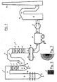
- the coal power plant according to FIG. 1 has a boiler 1 with a combustion chamber 2 for a dry firing, wherein an ash hopper 3 adjoins the combustion chamber 2.
- the boiler 1 further includes heat exchanger 4, to the housing, another ash hopper 5 connects.
- the boiler 1 is connected via a flue gas duct 6 with a denitrification catalyst 7.
- the latter has a plurality of catalyst stages 8, which are each composed of modules 9 (see Figure 2).
- the dimensions of the channels formed by the modules 9 are 7.1 mm ⁇ 7.1 mm ⁇ 1000 mm.
- the denitrification catalyst 7 is adjoined by a regenerative air preheater 10, whose internals can be seen from the half-view of FIG. This is followed by an electrostatic precipitator 11, an induced draft fan 12 and a REA scrubber 13, from which the purified flue gases pass into a chimney 14.
- the flue gas duct 6 adjoins the ash hopper 5 with a horizontal section 15.
- Grobascheabscheider 16 is provided which comprises a swinging suspended screen 17 and a rest position of the screen 17 defining stop 18.
- the flue gas stream displaces the screen 17 of the coarse ash precipitator 16 in oscillating motions, due to pulsations in the constant exhaust gas flow and due to changing throughputs in the event of load changes.
- the oscillating movements cause glued or sintered coarse ash particles, which are stuck on the sieve 17, fall from this and get into the ash funnel 5.
- This effect is supported by the fact that the sieve 17 strikes the stop 18 every now and then, which leads to the centrifuging of the particles.
- the channels of the catalyst stages 8 are protected against the entry of coarse ash particles (> 5 mm), which otherwise can settle in the channels and block them.
- the air preheater 10 is protected.
- the horizontal section according to FIG. 4 shows that the sieve 17 consists of plane surface sections 19 standing at an angle to one another. These form folds 20, which are directed against the flow direction. The coarse ash particles thus meet obliquely on the surface portions 19 and are derived parallel to these. This reduces the tendency for the ash particles to get caught in the screen openings. Moreover, the fold-shaped design of the screen 17 increases its passage area, so that you can work without increasing the pressure loss with relatively small screen openings.
- Figure 5 shows that the surface portions 19 of the screen 17 are drawn on frame 21, which are fixed to a support frame 22 and can be individually replaced. As can be seen from the rear view of Figure 5, the support frame 22 is located on the downstream side of the screen 17th
- the sieve 17 is suspended in section 15 of the flue gas duct 6.
- Hanging elements 23, which are shown in FIG. 5, serve for this purpose.
- the sieve may be flat when the suspension is pendulum or may be rigidly arranged in the smoke duct in the case of a fold-like design, although the described combination of these features is particularly advantageous.
- pendulum suspension any other mounting options come into question, even those in which the restoring force is not supplied by gravity, but by the force of a spring or an elastic linkage.
- load weights is equally possible.
- the stop defining the rest position can cause a pre-deflection of the screen.
- FIGS. 5 and 6 is particularly advantageous, it can also be modified.
Claims (13)
- Centrale à charbon avec- une cuve (1), pouvant être chauffée par un chauffage à sec,- un canal de gaz de fumée (6) relié à la cuve (1) qui mène à un catalyseur de dénitrification (7), et- un séparateur des cendres grossières (16) qui est disposé en amont du catalyseur (7) dans une section (15) du canal de gaz de fumée (6) et présente un tamis (17) qui s'étend sensiblement sur toute la section transversale du canal de gaz de fumée (6), caractérisée en ce que
le tamis (17) du séparateur des cendres grossières (16) peut être dévié par le flux des gaz de fumée contre l'effet d'une force de rappel d'une position de repos. - Centrale à charbon selon la revendication 1, caractérisée en ce que la position de repos du tamis (17) est définie par une butée (18).
- Centrale à charbon selon la revendication 1 ou 2, caractérisée en ce que la section (15) du canal de gaz de fumée (6), dans laquelle est disposé le séparateur des cendres grossières (16), s'étend sensiblement horizontalement, et en ce que le tamis (17) du séparateur de cendres grossières (16) est accroché d'une manière articulée.
- Centrale à charbon selon la revendication 3, caractérisée en ce que la butée (18) définissant la position de repos du tamis (17), par rapport à la suspension articulée du tamis (17), est décalée vers l'aval.
- Centrale à charbon avec- une cuve (1), pouvant être chauffée par un chauffage à sec,- un canal de gaz de fumée (6) relié à la cuve (1) qui mène à un catalyseur de dénitrification (7), et- un séparateur de cendres grossières (16) qui est disposé en amont du catalyseur (7) dans une section (15) du canal de gaz de fumée (6) et présente un tamis (17) qui s'étend sensiblement sur toute la section transversale du canal de gaz de fumée (6), caractérisé en ce que
le tamis (17) du séparateur des cendres grossières (16) forme des plis (20) orientés vers l'amont, s'étendant sensiblement parallèlement les uns aux autres. - Centrale à charbon selon la revendication 5, caractérisée en ce que les plis (20) du tamis (17) sont formés par des sections de face planes (19) s'étendant angulairement les unes aux autres.
- Centrale à charbon selon la revendication 6, caractérisée en ce que les sections de face (19) du tamis (17) s'appliquent à des treillis de support (24) disposés en aval.
- Centrale à charbon selon la revendication 7, caractérisée en ce que les sections de face (19) du tamis (17) et les treillis de support associés (24) sont montés sur des cadres (21) qui sont fixés à un bâti de support (22).
- Centrale à charbon selon l'une des revendications 1 à 8, caractérisée en ce que la section (15) du canal de gaz de fumée (6), qui contient le séparateur des cendres grossières (16), fait suite à une trémie de cendres (5), et en ce que le séparateur de cendres grossières (16) est disposé à la transition de la trémie de cendres (5) à la section (15) du canal de gaz de fumée (6).
- Séparateur des cendres grossières (16)
avec une section de canal de gaz de fumée (15),
et un tamis (17), qui est disposé dans la section (15) du canal des gaz de fumée, où le tamis (17) s'étend sensiblement sur toute la section transversale de la section (15) du canal de gaz de fumée et présente des plis (20) s'étendant sensiblement parallèlement les uns aux autres, et où le tamis (17) est disposé de telle sorte dans la section (15) du canal des gaz de fumée que des particules de cendres entraînées par les gaz de fumée heurtent en biais la face de tamisage formée par les plis (20) et tombent des plis (20). - Séparateur des cendres grossières (16) selon la revendication 10, caractérisé en ce que les plis (20) du tamis (17) sont formés par des sections de face plane (19) s'étendant angulairement les unes aux autres.
- Séparateur des cendres grossières selon la revendication 11, caractérisé en ce que les sections de face (19) du tamis (17) s'appliquent à des treillis de support (24) disposés en aval.
- Séparateur des cendres grossières selon la revendication 12, caractérisé en ce que les sections de face (19) du tamis (17) et les treillis de support associés (24) sont montés sur des cadres (21), qui sont fixés à un bâti de support (22).
Applications Claiming Priority (3)
| Application Number | Priority Date | Filing Date | Title |
|---|---|---|---|
| DE10227639A DE10227639B4 (de) | 2002-06-20 | 2002-06-20 | Kohlekraftwerk |
| DE10227639 | 2002-06-20 | ||
| PCT/EP2002/014633 WO2004001290A1 (fr) | 2002-06-20 | 2002-12-20 | Centrale a charbon |
Publications (2)
| Publication Number | Publication Date |
|---|---|
| EP1514057A1 EP1514057A1 (fr) | 2005-03-16 |
| EP1514057B1 true EP1514057B1 (fr) | 2007-11-28 |
Family
ID=29761317
Family Applications (1)
| Application Number | Title | Priority Date | Filing Date |
|---|---|---|---|
| EP02795252A Expired - Lifetime EP1514057B1 (fr) | 2002-06-20 | 2002-12-20 | Centrale a charbon |
Country Status (5)
| Country | Link |
|---|---|
| US (1) | US6994036B2 (fr) |
| EP (1) | EP1514057B1 (fr) |
| DE (2) | DE10227639B4 (fr) |
| PT (1) | PT1514057E (fr) |
| WO (1) | WO2004001290A1 (fr) |
Families Citing this family (31)
| Publication number | Priority date | Publication date | Assignee | Title |
|---|---|---|---|---|
| SE527104C2 (sv) * | 2004-05-21 | 2005-12-20 | Alstom Technology Ltd | Sätt och anordning för avskiljning av stoftpartiklar |
| PT1690588E (pt) * | 2005-02-14 | 2010-05-31 | Evonik Energy Services Gmbh | Disposição para separação de cinzas grosseiras a partir de um escoamento de gases de combustão |
| DE102006021670A1 (de) * | 2006-05-10 | 2007-11-15 | Lentjes Gmbh | Grobascheabscheider |
| US8052766B2 (en) * | 2006-08-16 | 2011-11-08 | Alstom Technology Ltd | Device and method for cleaning selective catalytic reduction protective devices |
| AT10369U1 (de) * | 2008-01-16 | 2009-02-15 | Kirchdorfer Zementwerk Hofmann | Rauchgasreinigungsanlage |
| US8475573B2 (en) * | 2009-08-25 | 2013-07-02 | Babcock & Wilcox Power Generation Group, Inc. | System and method for protection of SCR catalyst |
| US8425850B1 (en) | 2010-12-08 | 2013-04-23 | American Electric Power Company, Inc. | Large particle ash mitigation system |
| JP5854777B2 (ja) * | 2011-11-16 | 2016-02-09 | 三菱日立パワーシステムズ株式会社 | 排ガス処理装置 |
| JP5762255B2 (ja) * | 2011-11-16 | 2015-08-12 | 三菱日立パワーシステムズ株式会社 | 排ガス処理装置 |
| JP5762325B2 (ja) * | 2012-01-30 | 2015-08-12 | 三菱日立パワーシステムズ株式会社 | 排ガス処理装置 |
| JP5854863B2 (ja) * | 2012-01-30 | 2016-02-09 | 三菱日立パワーシステムズ株式会社 | 排ガス処理装置 |
| US8936662B2 (en) * | 2012-10-02 | 2015-01-20 | Integrated Global Services, Inc. | Apparatus and methods for large particle ash separation from flue gas using screens having semi-elliptical cylinder surfaces |
| CN103234211B (zh) * | 2013-04-19 | 2015-11-04 | 中工国际工程股份有限公司 | 自带一级陶瓷多管旋风除尘的生物质锅炉 |
| JP6005015B2 (ja) | 2013-09-04 | 2016-10-12 | 三菱日立パワーシステムズ株式会社 | ダクト壁面構造 |
| CN103807864B (zh) * | 2013-11-30 | 2016-06-22 | 信宜市伟昌纸品厂有限公司 | 环保锅炉 |
| JP5972857B2 (ja) | 2013-12-25 | 2016-08-17 | 三菱重工業株式会社 | 排気ダクト及びボイラ |
| FI20145240L (fi) | 2014-03-17 | 2015-09-18 | Valmet Technologies Oy | Polttokattila |
| CN104390473A (zh) * | 2014-10-20 | 2015-03-04 | 何本科 | 一种冶炼炉 |
| JP6385266B2 (ja) * | 2014-12-12 | 2018-09-05 | 三菱日立パワーシステムズ株式会社 | 排気ダクト及びボイラ |
| CN104874250A (zh) * | 2015-02-03 | 2015-09-02 | 李新光 | 消烟除尘脱硫净化过滤系统 |
| CN104864378A (zh) * | 2015-05-28 | 2015-08-26 | 苏州斯洛莱自动化设备有限公司 | 一种高效环保立式锅炉 |
| CN104832905A (zh) * | 2015-05-28 | 2015-08-12 | 苏州斯洛莱自动化设备有限公司 | 一种塔形煤粉环保锅炉 |
| CN104930489B (zh) * | 2015-07-16 | 2017-01-11 | 山东圣威新能源有限公司 | 一种立式蒸汽锅炉 |
| CN105258104A (zh) * | 2015-09-17 | 2016-01-20 | 哈尔滨市金京锅炉有限公司 | 一种立式节能锅炉 |
| CN106225495A (zh) * | 2016-08-28 | 2016-12-14 | 桂林新艺制冷设备有限责任公司 | 一种冶炼炉 |
| CN106352710A (zh) * | 2016-08-28 | 2017-01-25 | 桂林新艺制冷设备有限责任公司 | 一种除尘冶炼炉 |
| EP3417927A1 (fr) | 2017-06-23 | 2018-12-26 | Yara International ASA | Système rcs destiné à éliminer les cendres dans un flux de gaz de combustion généré dans un système de combustion |
| RU2743913C2 (ru) * | 2019-06-11 | 2021-03-01 | Борис Петрович Толкачев | Жалюзийный щелевой золоуловитель |
| JP7391651B2 (ja) | 2019-12-13 | 2023-12-05 | 三菱重工業株式会社 | 脱硝装置及びボイラシステム並びに脱硝装置の設置方法 |
| CN111672306A (zh) * | 2020-06-22 | 2020-09-18 | 济南鸿泰华丰机械有限公司 | 一种环保节能脱硫装置 |
| CN113058345A (zh) * | 2021-04-20 | 2021-07-02 | 安徽中电环保材料股份有限公司 | 一种推焦干熄焦除尘器及其防静电细纤维除尘滤袋 |
Family Cites Families (9)
| Publication number | Priority date | Publication date | Assignee | Title |
|---|---|---|---|---|
| DE838676C (de) * | 1949-06-21 | 1952-05-12 | Waagner Biro Ag | Filteranlage fuer Gase |
| FR1387107A (fr) * | 1963-11-12 | 1965-01-29 | Appareil épurateur de fumée et de gaz | |
| DE1985666U (de) * | 1968-02-12 | 1968-05-22 | Peter Bender | Russfaenger mit vergroesserter heizflaeche. |
| CA929036A (en) * | 1971-02-01 | 1973-06-26 | P. Knight Thomas | Garbage disposal plant |
| US5318755A (en) * | 1992-11-30 | 1994-06-07 | A. Ahlstrom Corporation | Method and apparatus for cleaning flue gases |
| DE4436207A1 (de) * | 1994-01-06 | 1995-07-13 | Ver Energiewerke Ag | Anordnung zum Schutz eines Katalysators im Rauchgaszug einer Feuerungsanlage, insbesondere eines kohlenstaubgefeuerten Dampfkessels oder einer Müllverbrennungsanlage |
| JPH08117559A (ja) * | 1994-10-25 | 1996-05-14 | Mitsubishi Heavy Ind Ltd | 石炭焚ボイラの脱硝装置 |
| US5785936A (en) * | 1994-12-02 | 1998-07-28 | Northeastern University | Simultaneous control of SO2, NOx, HCl, and particulates by in-furnace high-temperature sorbent injection and particulate removal |
| EP0764455B1 (fr) | 1995-09-25 | 2002-11-20 | Sintokogio, Ltd. | Filtre pour l'élimination de particules de suie des gaz d'échappement et dispositif l'utilisant |
-
2002
- 2002-06-20 DE DE10227639A patent/DE10227639B4/de not_active Expired - Lifetime
- 2002-12-20 EP EP02795252A patent/EP1514057B1/fr not_active Expired - Lifetime
- 2002-12-20 DE DE50211301T patent/DE50211301D1/de not_active Expired - Lifetime
- 2002-12-20 US US10/500,513 patent/US6994036B2/en not_active Expired - Lifetime
- 2002-12-20 PT PT02795252T patent/PT1514057E/pt unknown
- 2002-12-20 WO PCT/EP2002/014633 patent/WO2004001290A1/fr active Search and Examination
Also Published As
| Publication number | Publication date |
|---|---|
| DE10227639A1 (de) | 2004-01-22 |
| US20050061261A1 (en) | 2005-03-24 |
| WO2004001290A1 (fr) | 2003-12-31 |
| PT1514057E (pt) | 2008-02-12 |
| DE10227639B4 (de) | 2006-06-22 |
| US6994036B2 (en) | 2006-02-07 |
| EP1514057A1 (fr) | 2005-03-16 |
| DE50211301D1 (de) | 2008-01-10 |
Similar Documents
| Publication | Publication Date | Title |
|---|---|---|
| EP1514057B1 (fr) | Centrale a charbon | |
| EP1690588B1 (fr) | Dispositif pour séparer de cendres grossières d'un courant de gaz de fumée | |
| EP1855056B1 (fr) | Conduit de de gaz de combustion avec séparateur de cendres grossières | |
| EP0505881B1 (fr) | Procédé et dispositif de régénération des catalyseurs De-NOx épuisés | |
| CN107970772A (zh) | 一种scr烟气脱硝装置 | |
| JPH0295415A (ja) | 排ガス脱硝装置 | |
| WO2014006027A1 (fr) | Procédé d'épuration de gaz de fumées et installation de filtration correspondante | |
| DE102009044117A1 (de) | Horizontal angeströmter, verschmutzungsresistenter Tropfenabscheider mit rohrförmigen Prallkörpern und Lamellen | |
| WO1986001739A1 (fr) | Systeme pour la separation de gouttes de liquide d'un ecoulement gazeux dans une conduite verticale | |
| WO2011018322A1 (fr) | Procédé et dispositif de réduction d'oxydes d'azote de gaz de combustion contenant des poussières au moyen d'un catalyseur à réduction catalytique sélective | |
| EP1064081B1 (fr) | Corps de pot catalytique | |
| WO2001094023A1 (fr) | Depoussiereur electrostatique | |
| WO2010015009A1 (fr) | Procédé et dispositif de nettoyage et de dépoussiérage de gaz d’échappement résultant de processus de combustion | |
| CN207929005U (zh) | 一种scr烟气脱硝装置 | |
| WO2007042312A1 (fr) | Separateur de gouttes efficace | |
| EP0826409B1 (fr) | Procédé de réduction de la concentration d'oxydes d'azote dans des gaz effluents contenant des poussières | |
| DE19547735B4 (de) | Staubsammler | |
| EP2399660A2 (fr) | Séparateur inertiel de particules | |
| EP0549951B1 (fr) | Cheminée | |
| DE10311406B4 (de) | Filteranordnung | |
| DE202010002473U1 (de) | Anlage zum Entsticken von Rauchgas mit einer Abblasvorrichtung | |
| DE2753302A1 (de) | Vorrichtung zum entstauben von gasen | |
| DE3102403A1 (de) | Fluidreinigungssystem | |
| DE102009037476A1 (de) | SCR-Katalysator mit Druckluftanlage | |
| DE102016124706A1 (de) | Wirbelschichtströmungsreaktor |
Legal Events
| Date | Code | Title | Description |
|---|---|---|---|
| PUAI | Public reference made under article 153(3) epc to a published international application that has entered the european phase |
Free format text: ORIGINAL CODE: 0009012 |
|
| 17P | Request for examination filed |
Effective date: 20041222 |
|
| AK | Designated contracting states |
Kind code of ref document: A1 Designated state(s): AT BE BG CH CY CZ DE DK EE ES FI FR GB GR IE IT LI LU MC NL PT SE SI SK TR |
|
| 17Q | First examination report despatched |
Effective date: 20070220 |
|
| GRAP | Despatch of communication of intention to grant a patent |
Free format text: ORIGINAL CODE: EPIDOSNIGR1 |
|
| GRAS | Grant fee paid |
Free format text: ORIGINAL CODE: EPIDOSNIGR3 |
|
| GRAA | (expected) grant |
Free format text: ORIGINAL CODE: 0009210 |
|
| AK | Designated contracting states |
Kind code of ref document: B1 Designated state(s): AT BE BG CH CY CZ DE DK EE ES FI FR GB GR IE IT LI LU MC NL PT SE SI SK TR |
|
| REG | Reference to a national code |
Ref country code: GB Ref legal event code: FG4D Free format text: NOT ENGLISH |
|
| REG | Reference to a national code |
Ref country code: IE Ref legal event code: FG4D Free format text: LANGUAGE OF EP DOCUMENT: GERMAN |
|
| REG | Reference to a national code |
Ref country code: CH Ref legal event code: EP |
|
| REF | Corresponds to: |
Ref document number: 50211301 Country of ref document: DE Date of ref document: 20080110 Kind code of ref document: P |
|
| REG | Reference to a national code |
Ref country code: PT Ref legal event code: SC4A Free format text: AVAILABILITY OF NATIONAL TRANSLATION Effective date: 20080130 |
|
| GBT | Gb: translation of ep patent filed (gb section 77(6)(a)/1977) |
Effective date: 20080124 |
|
| REG | Reference to a national code |
Ref country code: PT Ref legal event code: PD4A Owner name: EVONIK ENERGY SERVICES GMBH, DE Effective date: 20080414 Ref country code: PT Ref legal event code: PD4A Owner name: EVONIK ENCOTEC GMBH, DE Effective date: 20080414 |
|
| PG25 | Lapsed in a contracting state [announced via postgrant information from national office to epo] |
Ref country code: SE Free format text: LAPSE BECAUSE OF FAILURE TO SUBMIT A TRANSLATION OF THE DESCRIPTION OR TO PAY THE FEE WITHIN THE PRESCRIBED TIME-LIMIT Effective date: 20080228 Ref country code: ES Free format text: LAPSE BECAUSE OF FAILURE TO SUBMIT A TRANSLATION OF THE DESCRIPTION OR TO PAY THE FEE WITHIN THE PRESCRIBED TIME-LIMIT Effective date: 20080311 |
|
| PG25 | Lapsed in a contracting state [announced via postgrant information from national office to epo] |
Ref country code: SI Free format text: LAPSE BECAUSE OF FAILURE TO SUBMIT A TRANSLATION OF THE DESCRIPTION OR TO PAY THE FEE WITHIN THE PRESCRIBED TIME-LIMIT Effective date: 20071128 Ref country code: BG Free format text: LAPSE BECAUSE OF FAILURE TO SUBMIT A TRANSLATION OF THE DESCRIPTION OR TO PAY THE FEE WITHIN THE PRESCRIBED TIME-LIMIT Effective date: 20080228 Ref country code: FI Free format text: LAPSE BECAUSE OF FAILURE TO SUBMIT A TRANSLATION OF THE DESCRIPTION OR TO PAY THE FEE WITHIN THE PRESCRIBED TIME-LIMIT Effective date: 20071128 |
|
| BERE | Be: lapsed |
Owner name: STEAG ENCOTEC G.M.B.H. Effective date: 20071231 |
|
| PG25 | Lapsed in a contracting state [announced via postgrant information from national office to epo] |
Ref country code: MC Free format text: LAPSE BECAUSE OF NON-PAYMENT OF DUE FEES Effective date: 20071231 Ref country code: DK Free format text: LAPSE BECAUSE OF FAILURE TO SUBMIT A TRANSLATION OF THE DESCRIPTION OR TO PAY THE FEE WITHIN THE PRESCRIBED TIME-LIMIT Effective date: 20071128 Ref country code: CZ Free format text: LAPSE BECAUSE OF FAILURE TO SUBMIT A TRANSLATION OF THE DESCRIPTION OR TO PAY THE FEE WITHIN THE PRESCRIBED TIME-LIMIT Effective date: 20071128 |
|
| REG | Reference to a national code |
Ref country code: CH Ref legal event code: PL |
|
| PG25 | Lapsed in a contracting state [announced via postgrant information from national office to epo] |
Ref country code: SK Free format text: LAPSE BECAUSE OF FAILURE TO SUBMIT A TRANSLATION OF THE DESCRIPTION OR TO PAY THE FEE WITHIN THE PRESCRIBED TIME-LIMIT Effective date: 20071128 |
|
| EN | Fr: translation not filed | ||
| PG25 | Lapsed in a contracting state [announced via postgrant information from national office to epo] |
Ref country code: BE Free format text: LAPSE BECAUSE OF NON-PAYMENT OF DUE FEES Effective date: 20071231 |
|
| NLT1 | Nl: modifications of names registered in virtue of documents presented to the patent office pursuant to art. 16 a, paragraph 1 |
Owner name: EVONIK ENCOTEC GMBH Owner name: EVONIK ENERGY SERVICES GMBH |
|
| PLBE | No opposition filed within time limit |
Free format text: ORIGINAL CODE: 0009261 |
|
| STAA | Information on the status of an ep patent application or granted ep patent |
Free format text: STATUS: NO OPPOSITION FILED WITHIN TIME LIMIT |
|
| PG25 | Lapsed in a contracting state [announced via postgrant information from national office to epo] |
Ref country code: FR Free format text: LAPSE BECAUSE OF FAILURE TO SUBMIT A TRANSLATION OF THE DESCRIPTION OR TO PAY THE FEE WITHIN THE PRESCRIBED TIME-LIMIT Effective date: 20080912 Ref country code: CH Free format text: LAPSE BECAUSE OF NON-PAYMENT OF DUE FEES Effective date: 20071231 Ref country code: LI Free format text: LAPSE BECAUSE OF NON-PAYMENT OF DUE FEES Effective date: 20071231 |
|
| 26N | No opposition filed |
Effective date: 20080829 |
|
| PG25 | Lapsed in a contracting state [announced via postgrant information from national office to epo] |
Ref country code: EE Free format text: LAPSE BECAUSE OF FAILURE TO SUBMIT A TRANSLATION OF THE DESCRIPTION OR TO PAY THE FEE WITHIN THE PRESCRIBED TIME-LIMIT Effective date: 20071128 Ref country code: GR Free format text: LAPSE BECAUSE OF FAILURE TO SUBMIT A TRANSLATION OF THE DESCRIPTION OR TO PAY THE FEE WITHIN THE PRESCRIBED TIME-LIMIT Effective date: 20080229 |
|
| PG25 | Lapsed in a contracting state [announced via postgrant information from national office to epo] |
Ref country code: CY Free format text: LAPSE BECAUSE OF FAILURE TO SUBMIT A TRANSLATION OF THE DESCRIPTION OR TO PAY THE FEE WITHIN THE PRESCRIBED TIME-LIMIT Effective date: 20071128 |
|
| PG25 | Lapsed in a contracting state [announced via postgrant information from national office to epo] |
Ref country code: LU Free format text: LAPSE BECAUSE OF NON-PAYMENT OF DUE FEES Effective date: 20071220 |
|
| PG25 | Lapsed in a contracting state [announced via postgrant information from national office to epo] |
Ref country code: IT Free format text: LAPSE BECAUSE OF NON-PAYMENT OF DUE FEES Effective date: 20071231 |
|
| REG | Reference to a national code |
Ref country code: NL Ref legal event code: TD Effective date: 20111214 |
|
| REG | Reference to a national code |
Ref country code: DE Ref legal event code: R081 Ref document number: 50211301 Country of ref document: DE Owner name: STEAG ENERGY SERVICES GMBH, DE Free format text: FORMER OWNER: EVONIK ENERGY SERVICES GMBH, 45128 ESSEN, DE Effective date: 20120217 |
|
| REG | Reference to a national code |
Ref country code: AT Ref legal event code: HC Ref document number: 379750 Country of ref document: AT Kind code of ref document: T Owner name: STEAG ENERGY SERVICES GMBH, DE Effective date: 20120427 |
|
| PGFP | Annual fee paid to national office [announced via postgrant information from national office to epo] |
Ref country code: DE Payment date: 20211210 Year of fee payment: 20 Ref country code: AT Payment date: 20211222 Year of fee payment: 20 Ref country code: PT Payment date: 20211209 Year of fee payment: 20 Ref country code: IE Payment date: 20211222 Year of fee payment: 20 Ref country code: GB Payment date: 20211221 Year of fee payment: 20 |
|
| PGFP | Annual fee paid to national office [announced via postgrant information from national office to epo] |
Ref country code: NL Payment date: 20211221 Year of fee payment: 20 |
|
| PGFP | Annual fee paid to national office [announced via postgrant information from national office to epo] |
Ref country code: TR Payment date: 20211216 Year of fee payment: 20 |
|
| REG | Reference to a national code |
Ref country code: DE Ref legal event code: R071 Ref document number: 50211301 Country of ref document: DE |
|
| REG | Reference to a national code |
Ref country code: NL Ref legal event code: MK Effective date: 20221219 |
|
| REG | Reference to a national code |
Ref country code: GB Ref legal event code: PE20 Expiry date: 20221219 |
|
| PG25 | Lapsed in a contracting state [announced via postgrant information from national office to epo] |
Ref country code: GB Free format text: LAPSE BECAUSE OF EXPIRATION OF PROTECTION Effective date: 20221219 |
|
| REG | Reference to a national code |
Ref country code: IE Ref legal event code: MK9A |
|
| REG | Reference to a national code |
Ref country code: AT Ref legal event code: MK07 Ref document number: 379750 Country of ref document: AT Kind code of ref document: T Effective date: 20221220 |
|
| PG25 | Lapsed in a contracting state [announced via postgrant information from national office to epo] |
Ref country code: IE Free format text: LAPSE BECAUSE OF EXPIRATION OF PROTECTION Effective date: 20221220 |