EP1513388A2 - Television tuner including distribution connectors - Google Patents
Television tuner including distribution connectors Download PDFInfo
- Publication number
- EP1513388A2 EP1513388A2 EP04020661A EP04020661A EP1513388A2 EP 1513388 A2 EP1513388 A2 EP 1513388A2 EP 04020661 A EP04020661 A EP 04020661A EP 04020661 A EP04020661 A EP 04020661A EP 1513388 A2 EP1513388 A2 EP 1513388A2
- Authority
- EP
- European Patent Office
- Prior art keywords
- side plate
- connector
- television
- distributor
- wide
- Prior art date
- Legal status (The legal status is an assumption and is not a legal conclusion. Google has not performed a legal analysis and makes no representation as to the accuracy of the status listed.)
- Withdrawn
Links
- 239000002184 metal Substances 0.000 claims abstract description 13
- 238000002955 isolation Methods 0.000 description 4
- 230000037431 insertion Effects 0.000 description 1
- 238000003780 insertion Methods 0.000 description 1
- 230000010355 oscillation Effects 0.000 description 1
- 238000011144 upstream manufacturing Methods 0.000 description 1
Images

Classifications
-
- H—ELECTRICITY
- H05—ELECTRIC TECHNIQUES NOT OTHERWISE PROVIDED FOR
- H05K—PRINTED CIRCUITS; CASINGS OR CONSTRUCTIONAL DETAILS OF ELECTRIC APPARATUS; MANUFACTURE OF ASSEMBLAGES OF ELECTRICAL COMPONENTS
- H05K9/00—Screening of apparatus or components against electric or magnetic fields
- H05K9/0007—Casings
- H05K9/006—Casings specially adapted for signal processing applications, e.g. CATV, tuner, antennas amplifier
Definitions
- the distribution unit may further include a second wide-band amplifier provided between the distributor and the tuner unit.
- the second wide-band amplifier may be arranged in a position next to the distributor and near the shield plate.
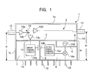
- a circuit board (not shown) for configuring the first shield plate 2, the second shield plate 5, and the third shield plate 6 so as to stand and for arranging various circuits in the first compartment area 3 and the second compartment area 4 (including the first compartment 7, the second compartment, and the third compartment 9) is accommodated in the metal frame body 1.
- a first connector (for example, an F-type coaxial connector) 10 to which a television signal is input is mounted in a position on the third side plate 1c adjacent to the first compartment area 3.
- a second connector (for example, a coaxial pin plug) 11 for outputting a television signal is mounted on the fourth side plate 1d.
- the mounting height H of the first connector 10 (the distance from the second side plate 1b to the central axis of the first connector 10) is equal to the mounting height H of the second connector 11 (the distance from the second side plate 1b to the central axis of the second connector 11).
- a plurality of terminals 12 is mounted in a row with approximately regular intervals on the second side plate 1b.
- the high-frequency amplifier 14b is arranged in a position of the second shield plate 5 (on a rear face of the circuit board).
- the interstage tuning circuit 14c includes a tuning circuit section for the UHF band and a tuning circuit section for the VHF band.
- the interstage tuning circuit 14c is arranged in half the second compartment 8 near the second shield plate 5.
- the oscillator 14d is arranged in the third compartment 9.
- the mixer circuit 14e is arranged in half the second compartment 8 near the fourth side plate 1d.
- the television signal input from the first connector 10 to the first wide-band amplifier 13a is amplified and then distributed into two television signals by the distributor 13b.
- One of the distributed television signals is input to the input-tuning circuit 14a in the first compartment 7 via the second wide-band amplifier 13c.
- the one of the distributed television signals is input to the mixer circuit 14e via the high-frequency amplifier 14b and the interstage tuning circuit 14c, and is finally converted into an intermediate-frequency signal in the mixer circuit 14e by being combined with an oscillation signal.
- the converted intermediate-frequency signal is output from the terminals 12.
- the other of the television signals distributed from the distributor 13b is output from the second connector 11 via the third wide-band amplifier 13d and input to an external television tuner.
- Fig. 2 shows an example of use of a television tuner 41 according to the present invention.
- the television tuner 41 is mounted on a mother board 40.
- the terminals 12 are inserted into through-holes in the mother board 40.
- An external television tuner 42 includes a connector (for example, a pin jack) to which a television signal is input.
- the mounting height of the connector 43 of the external television tuner 42 is equal to the mounting height of the second connector 11 of the television tuner 41 according to the present invention.
- the external television tuner 42 is mounted on the mother board 40 such that the connector 43 faces the fourth side plate 1d of the television tuner 41, and terminals 44 are inserted in the mother board 40.
- the connector 43 of the external television tuner 42 is connected to the second connector 11 of the television tuner 41.
- the television tuner 41 and the external television tuner 42 are mounted together on the mother board 40 with the second connector 11 and the connector 43 connected to each other.
- two television tuners can be easily connected to each other without using special means, such as a cable or the like, to connect the television tuners.
Landscapes
- Engineering & Computer Science (AREA)
- Signal Processing (AREA)
- Microelectronics & Electronic Packaging (AREA)
- Structure Of Receivers (AREA)
- Input Circuits Of Receivers And Coupling Of Receivers And Audio Equipment (AREA)
Abstract
Description
Claims (5)
- A television tuner comprising a distribution unit at least including a distributor for distributing an input television signal into two television signals; a tuner unit for frequency-converting one of the distributed television signals and for outputting an intermediate-frequency signal; and a rectangular metal frame body having a first side plate, a second side plate, a third side plate, and a fourth side plate, the metal frame body containing therein the distribution unit and the tuner unit, wherein:a shield plate divides the metal frame body into a first compartment area near the first side plate and a second compartment area near the second side plate, which faces the first side plate;the distributor is arranged in the first compartment area;the tuner unit is arranged in the second compartment area;terminals to be connected to a mother board are mounted on the second side plate;a first connector to which said input television signal is input is mounted in a position on the third side plate adjacent to the first compartment area;a second connector for outputting the other of the distributed television signals distributed by the distributor is mounted in a position on the fourth side plate adjacent to the first compartment area; anda distance from the second side plate to a central axis of the first connector is equal to a distance from the second side plate to a central axis of the second connector.
- The television tuner according to Claim 1, wherein:the distribution unit further includes a first wide-band amplifier provided between the first connector and the distributor;the first wide-band amplifier is arranged in a position within the first compartment area near the first connector; andthe distributor is arranged in a position next to the first wide-band amplifier and near the fourth side plate.
- The television tuner according to Claim 1 or 2, wherein:the distribution unit further includes a second wide-band amplifier provided between the distributor and the tuner unit; andthe second wide-band amplifier is arranged in a position next to the distributor and near the shield plate.
- The television tuner according to Claim 1, 2 or 3, wherein:the distribution unit further includes a third wide-band amplifier provided between the distributor and the second connector: andthe third wide-band amplifier is arranged in a position next to the distributor and near the fourth side plate.
- The television tuner according to any of Claims 1 to 4, wherein the second connector is a pin plug.
Applications Claiming Priority (2)
| Application Number | Priority Date | Filing Date | Title |
|---|---|---|---|
| JP2003270952U JP3100213U (en) | 2003-09-03 | 2003-09-03 | Television tuner |
| JP2003270952 | 2003-09-03 |
Publications (2)
| Publication Number | Publication Date |
|---|---|
| EP1513388A2 true EP1513388A2 (en) | 2005-03-09 |
| EP1513388A3 EP1513388A3 (en) | 2008-12-24 |
Family
ID=34209049
Family Applications (1)
| Application Number | Title | Priority Date | Filing Date |
|---|---|---|---|
| EP04020661A Withdrawn EP1513388A3 (en) | 2003-09-03 | 2004-08-31 | Television tuner including distribution connectors |
Country Status (3)
| Country | Link |
|---|---|
| US (1) | US7289167B2 (en) |
| EP (1) | EP1513388A3 (en) |
| JP (1) | JP3100213U (en) |
Families Citing this family (15)
| Publication number | Priority date | Publication date | Assignee | Title |
|---|---|---|---|---|
| JP3096172U (en) * | 2003-02-27 | 2003-09-05 | アルプス電気株式会社 | Television tuner |
| JP4148214B2 (en) * | 2004-11-09 | 2008-09-10 | 船井電機株式会社 | LCD television equipment |
| JP2006211530A (en) * | 2005-01-31 | 2006-08-10 | Sharp Corp | Integrated tuner for satellite and terrestrial broadcast reception |
| JP2007036649A (en) * | 2005-07-27 | 2007-02-08 | Orion Denki Kk | Television broadcast receiver |
| JP4063841B2 (en) * | 2005-09-09 | 2008-03-19 | シャープ株式会社 | Receiving device, receiving system |
| JP4350084B2 (en) * | 2005-11-07 | 2009-10-21 | シャープ株式会社 | Receiver and receiver system |
| JP2007251446A (en) * | 2006-03-15 | 2007-09-27 | Sharp Corp | Receiving device, receiving system |
| JP2007251702A (en) * | 2006-03-17 | 2007-09-27 | Sharp Corp | Receiving device, receiving system |
| JP4338710B2 (en) * | 2006-03-27 | 2009-10-07 | シャープ株式会社 | Receiver and receiver system |
| JP2008294553A (en) * | 2007-05-22 | 2008-12-04 | Univ Of Electro-Communications | Small digital TV tuner unit |
| JP2010200129A (en) * | 2009-02-26 | 2010-09-09 | Hitachi Media Electoronics Co Ltd | Tuner |
| JP4856258B2 (en) * | 2010-03-31 | 2012-01-18 | 株式会社東芝 | Tuner module and receiver |
| KR101320191B1 (en) * | 2010-12-30 | 2013-10-23 | 삼성전기주식회사 | Complex tuner module |
| JP5905319B2 (en) * | 2012-04-10 | 2016-04-20 | シャープ株式会社 | Receiving machine |
| US20170171593A1 (en) * | 2015-12-14 | 2017-06-15 | Le Holdings (Beijing) Co., Ltd. | Tuner unit module, tuner and electronic device |
Family Cites Families (14)
| Publication number | Priority date | Publication date | Assignee | Title |
|---|---|---|---|---|
| DE2932015C2 (en) * | 1978-08-07 | 1983-12-29 | Mitsumi Electric Co., Ltd., Tokyo | Shielding device for high frequency circuits |
| US4352209A (en) * | 1981-03-23 | 1982-09-28 | John Ma | Up-down frequency converter for cable T.V. |
| US5050238A (en) * | 1988-07-12 | 1991-09-17 | Sanyo Electric Co., Ltd. | Shielded front end receiver circuit with IF amplifier on an IC |
| JPH0396172A (en) | 1989-09-08 | 1991-04-22 | Tokyo Electric Co Ltd | Picture processing unit |
| US5369552A (en) * | 1992-07-14 | 1994-11-29 | Ncr Corporation | Multi-chip module with multiple compartments |
| JP2663823B2 (en) * | 1993-01-29 | 1997-10-15 | 松下電器産業株式会社 | High frequency device |
| JP3533033B2 (en) * | 1996-04-10 | 2004-05-31 | 松下電器産業株式会社 | High frequency device |
| JP3380685B2 (en) | 1996-07-12 | 2003-02-24 | アルプス電気株式会社 | High frequency electronic equipment |
| JP3753518B2 (en) * | 1997-10-24 | 2006-03-08 | シャープ株式会社 | Tuner for cable modem |
| US6160571A (en) * | 1998-05-04 | 2000-12-12 | Isg Broadband, Inc. | Compact cable tuner/transceiver |
| US6215656B1 (en) * | 1999-06-18 | 2001-04-10 | Dell Usa, L.P. | Method and apparatus for factory or user configurable external connectors |
| JP2003174278A (en) * | 2001-12-06 | 2003-06-20 | Alps Electric Co Ltd | Tuner unit |
| DE60233106D1 (en) * | 2001-12-19 | 2009-09-10 | Alps Electric Co Ltd | TV tuner unit |
| KR101015689B1 (en) * | 2002-07-25 | 2011-02-22 | 소니 주식회사 | Receiver and television receiver |
-
2003
- 2003-09-03 JP JP2003270952U patent/JP3100213U/en not_active Expired - Lifetime
-
2004
- 2004-08-31 EP EP04020661A patent/EP1513388A3/en not_active Withdrawn
- 2004-09-02 US US10/932,972 patent/US7289167B2/en not_active Expired - Fee Related
Also Published As
| Publication number | Publication date |
|---|---|
| US7289167B2 (en) | 2007-10-30 |
| US20050073612A1 (en) | 2005-04-07 |
| EP1513388A3 (en) | 2008-12-24 |
| JP3100213U (en) | 2004-05-13 |
Similar Documents
| Publication | Publication Date | Title |
|---|---|---|
| US7289167B2 (en) | Television tuner including distribution connectors | |
| JP2663823B2 (en) | High frequency device | |
| JP3100214U (en) | Television tuner | |
| US20010016949A1 (en) | Channel module apparatus for cable set-top box | |
| JP3533033B2 (en) | High frequency device | |
| EP1326439B1 (en) | Television tuner unit | |
| US7174140B2 (en) | RF system integrated with RF switch and RF modulation | |
| US7184102B2 (en) | Television tuner having input and output signals sufficiently isolated from each other | |
| KR100234947B1 (en) | Multi-tap high frequency modulator | |
| EP1978735A2 (en) | Television broadcast receiving apparatus | |
| US20040169776A1 (en) | Television tuner unit having a small motherboard-mounted surface area | |
| JPH09200068A (en) | Television signal changeover output circuit | |
| JP3083281U (en) | Electronic tuner | |
| JP2565808Y2 (en) | Satellite receiver | |
| JPH0347348Y2 (en) | ||
| JPS61101133A (en) | Low noise receiver | |
| JP3503001B2 (en) | booster | |
| KR940004393Y1 (en) | Satellite broadcasting apparatus | |
| US20080295136A1 (en) | High frequency receiving apparatus | |
| JPS63267024A (en) | Antenna booster mixer | |
| JP2004215150A (en) | Tuner for CATV | |
| KR101474131B1 (en) | Tripple tuner module | |
| JP2001053570A (en) | Plug-type equalizer | |
| JP2007124248A (en) | Television tuner | |
| KR101171530B1 (en) | High complex digital broadcasting receiving system |
Legal Events
| Date | Code | Title | Description |
|---|---|---|---|
| PUAI | Public reference made under article 153(3) epc to a published international application that has entered the european phase |
Free format text: ORIGINAL CODE: 0009012 |
|
| AK | Designated contracting states |
Kind code of ref document: A2 Designated state(s): AT BE BG CH CY CZ DE DK EE ES FI FR GB GR HU IE IT LI LU MC NL PL PT RO SE SI SK TR |
|
| AX | Request for extension of the european patent |
Extension state: AL HR LT LV MK |
|
| PUAL | Search report despatched |
Free format text: ORIGINAL CODE: 0009013 |
|
| AK | Designated contracting states |
Kind code of ref document: A3 Designated state(s): AT BE BG CH CY CZ DE DK EE ES FI FR GB GR HU IE IT LI LU MC NL PL PT RO SE SI SK TR |
|
| AX | Request for extension of the european patent |
Extension state: AL HR LT LV MK |
|
| 17P | Request for examination filed |
Effective date: 20090213 |
|
| AKX | Designation fees paid |
Designated state(s): DE FR GB |
|
| STAA | Information on the status of an ep patent application or granted ep patent |
Free format text: STATUS: THE APPLICATION HAS BEEN WITHDRAWN |
|
| 18W | Application withdrawn |
Effective date: 20090820 |