EP1513378A2 - Method and apparatus of coordinating operational feedback in a plasma cutter - Google Patents
Method and apparatus of coordinating operational feedback in a plasma cutter Download PDFInfo
- Publication number
- EP1513378A2 EP1513378A2 EP04016676A EP04016676A EP1513378A2 EP 1513378 A2 EP1513378 A2 EP 1513378A2 EP 04016676 A EP04016676 A EP 04016676A EP 04016676 A EP04016676 A EP 04016676A EP 1513378 A2 EP1513378 A2 EP 1513378A2
- Authority
- EP
- European Patent Office
- Prior art keywords
- plasma
- power source
- plasma cutting
- feedback
- torch
- Prior art date
- Legal status (The legal status is an assumption and is not a legal conclusion. Google has not performed a legal analysis and makes no representation as to the accuracy of the status listed.)
- Withdrawn
Links
Images

Classifications
-
- B—PERFORMING OPERATIONS; TRANSPORTING
- B23—MACHINE TOOLS; METAL-WORKING NOT OTHERWISE PROVIDED FOR
- B23K—SOLDERING OR UNSOLDERING; WELDING; CLADDING OR PLATING BY SOLDERING OR WELDING; CUTTING BY APPLYING HEAT LOCALLY, e.g. FLAME CUTTING; WORKING BY LASER BEAM
- B23K10/00—Welding or cutting by means of a plasma
- B23K10/006—Control circuits therefor
-
- H—ELECTRICITY
- H05—ELECTRIC TECHNIQUES NOT OTHERWISE PROVIDED FOR
- H05H—PLASMA TECHNIQUE; PRODUCTION OF ACCELERATED ELECTRICALLY-CHARGED PARTICLES OR OF NEUTRONS; PRODUCTION OR ACCELERATION OF NEUTRAL MOLECULAR OR ATOMIC BEAMS
- H05H1/00—Generating plasma; Handling plasma
- H05H1/24—Generating plasma
- H05H1/26—Plasma torches
- H05H1/32—Plasma torches using an arc
- H05H1/34—Details, e.g. electrodes, nozzles
- H05H1/36—Circuit arrangements
Definitions
- the present invention relates generally to plasma cutting systems and, more particularly, to a method and apparatus for coordinating operational feedback in a plasma cutter. Specifically, the present invention provides a system and method of serializing feedback from a plasma-cutting torch to a plasma-cutting power source.
- Plasma cutting is a process in which an electric arc is used to cut a workpiece.
- Plasma cutters typically include a power source, an air supply, and a torch.
- the torch or plasma torch is used to create and maintain the arc and plasma that perform the cutting.
- the plasma cutting power source receives an input voltage from a transmission power line or generator and provides an output voltage to a pair of output terminals, one of which is connected to an electrode and the other of which is connected to the workpiece.
- the air supply is used with most plasma cutters to help start the arc, provide the plasma gas to the torch, and cool the torch.
- a movable or fixed electrode serves as a cathode and a fixed nozzle serves an anode.
- the air supply moves the electrode and as the electrode moves away from the nozzle, it opens the nozzle, and a plasma jet is created.
- the plasma jet causes the arc to transfer to the work piece, and thus initiates the cutting process.
- a high frequency starter is used to initiate the cutting process.
- the power source is supplied with operational feedback from the torch and a processor, disposed in the power source, interprets the data and controls the operation of the plasma cutter.
- the processor of the power source is provided with feedback about the position of the torch trigger and whether all necessary torch components are securely in place at the torch. From the feedback, the processor determines whether to initiate cutting, pause cutting, discontinue cutting, or augment the operation of the plasma cutter during cutting.
- This feedback is typically provided via dedicated communications lines. Therefore, for each form of feedback that is sent from the torch to the power source, an individual communications line is connected between the power supply and cutting torch.
- This parallel feedback system presents numerous drawbacks.
- plasma cutting is a high voltage process and therefore the user must be mindful that precautionary measures must be taken to avoid improper operation. As such, it is necessary to determine whether specific conditions are present prior to the initiation of cutting. For example, before the power source responds to a request for operational power at the torch, the processor of the power source typically determines whether a retaining cup, fastened at the torch tip and securing the electrode, is in place. This ensures that the torch is in operating condition prior to cutting.
- the number of feedbacks is limited by the parallel feedback system. Specifically, since the feedback must be sent from the torch to the power source, the feedback must travel over a control cord connecting the torch and power source.
- plasma cutters are regularly subjected to harsh operating conditions associated with the operating environment in which they are placed and the nature of plasma cutting.
- plasma cutters are commonly operated within large manufacturing environments or at an in-field site.
- the plasma torch it is not uncommon for the plasma torch to be regularly disconnected from the power source for cleaning and maintenance. This repeated disconnection and reconnection can be particularly damaging to the electrical connections of the parallel feedback system. In either case, if the parallel feedback system fails, the plasma cutter must be removed from service and repaired or otherwise serviced.
- the present invention is directed to a system and method of coordinating operational feedback in a plasma cutter that overcomes the aforementioned drawbacks.
- the present invention provides a system and method of serializing feedback from a plasma-cutting torch to a plasma-cutting power source.
- the invention includes a plasma cutting power source, a plasma torch in communication with the plasma cutting power source, and a serialization circuit disposed within the plasma torch to control transmission of multiple feedback signals from the plasma torch to the plasma cutting power source.
- the serialization circuit receives the multiple feedback signals and places the feedback in a queue, such that the multiple feedback signals are sent from the queue to a processing unit in the power source via a single communications link.
- a plasma cutting system including a plasma cutting power source, a plasma torch operationally connected to the plasma cutting power source, and a serialization circuit disposed within the plasma torch.
- the serialization circuit is configured to control transmission of multiple feedback signals from the plasma torch to the plasma cutting power source.
- a method for providing feedback from a plasma torch to a remote power source including receiving feedback from a plurality of sensors disposed in the plasma torch. The method also includes arranging the feedback in a queue and sending the feedback to a remote power source in an order the feedback is arranged in the queue.
- a plasma torch assembly including a torch body enclosing a plasma-cutting electrode and a plurality of sensors.
- the plurality of sensors is configured to provide feedback regarding at least operational conditions of a plasma torch.
- a serializer is disposed within the torch body to receive feedback from the plurality of sensors and configured to transmit the feedback to a remote processing unit via a single communications link.
- the present invention is directed to an operational feedback system of a plasma cutter.
- the serial communications feedback system allows the power source, where operational control is managed, to be supplied with diversified feedback regarding the plasma cutting process while reducing manufacturing costs and the potential for a communications breakdown due to operational wear.
- the plasma cutting system 10 is a high voltage system with maximum open circuit output voltages ranging from approximately 230 Volts Direct Current (VDC) to over 300 VDC.
- the plasma cutting system 10 includes a power source 12 to condition raw power and regulate/control the cutting process.
- the power source includes a processor that, as will be described, receives operational feedback and controls the plasma cutting system 10 accordingly.
- Power source 12 includes a lifting means, such as a handle 14 which effectuates transportation from one site to another.
- Connected to the power source 12 is a torch 16 via cord 18.
- the torch 16 is defined at least by a torch body or housing 17 enclosing a plasma-cutting electrode 19.
- the cord 18 provides the torch 16 with power and serves as a communications link between the torch 16 and power source 12.
- the cord 18 contains two conductive paths. One conductive communications link or conductive path is dedicated to the transfer of power to energize the plasma-cutting electrode 19 and the other conductive path is dedicated to the transfer of feedback to the power source 12.
- the cord 18 contains one conductive path between the torch 16 and power source 12 to transfer both operational feedback and power. Specifically, a single conductive path is contained within the cord 18 that simultaneously transfers power and feedback from the plasma torch regarding the plasma cutting process.
- a work clamp 20 which is designed to hold a workpiece (not shown) to be cut.
- a cable 22 designed to provide a return path for the cutting current from the torch through the workpiece and the work clamp 20.
- Extending from a rear portion of power source 12 is power cable 24 having plug 26 for connecting the power source 12 to a portable power supply 28 or a transmission power receptacle (not shown).
- Power source 12 further includes an ON/OFF switch 30.
- torch 16 is placed in close proximity to a workpiece connected to clamp 20.
- a user may then activate a trigger lock (not shown), in response to which a feedback signal is sent from a trigger sensor disposed within the torch 16 and connected to the trigger lock in the torch 16.
- the signal is received by a serializing circuit disposed within the torch 16 and placed in a queue.
- the trigger lock signal is sent to the power source 12, via the cord 18, where a processing unit, disposed in the power source 12, processes the feedback.
- the user may then press the trigger switch (not shown).
- the trigger switch Upon pressing the trigger switch, another feedback signal is sent from the trigger sensor disposed within the torch 16.
- the trigger switch feedback is again sent to the serializing circuit within trigger 16 where it is placed in a queue and, after passing through the queue, the signal is sent to the processing unit of the power source 12.
- the power source processing unit causes power to be sent to the torch 16 to initiate a pilot arc. Shortly thereafter, a cutting arc is generated and the user may then slowly move the torch across the workpiece to cut the workpiece. The user may adjust the torch speed to reduce spark splatter and provide a more-penetrating cut.
- Additional sensors are included within the torch 16 to send additional feedback, specific to plasma cutting, back to the processing unit of power source 12.
- sensors to monitor air pressure, tip and electrode type, safety trigger, and consumable life are included.
- Other additional sensors to provide feedback regarding a plurality of plasma cutting operations may also be included.
- sensors may be constructed and disposed within the torch 16 to send feedback regarding power source activation, cup position, shorted component, torch temperature, trigger position, operation amperage, current transfer, and voltage drop, as well as any other operational conditions capable of being monitored.
- the serialization circuit allows signals from multiple sensors to be sent from the torch 16 to the power source 12 because, since the communications are serialized, only one communications link is necessary. That is, from each sensor, a feedback signal is generated and sent to the serializing circuit where the feedback signals are placed in a queue before being transferred along the cord 18 to the processing unit in the power source 12. Therefore, even though multiple feedback signals are sent from the torch 16 to the power source 12, the cord 18 may be smaller than traditional cords housing parallel communications links.
- the communications link also facilitates the transfer of power from the power source 12 to the torch 16. Accordingly, the communications link serves dual purposes and a single conductive means is included within the cord 18 to transmit the feedback to the power source and the power to the torch 16.
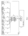
- a plurality of feedback sensors is disposed within plasma torch 16 including a consumable sensor 36, an electrode sensor 38, a cup sensor 40, a trigger sensor 42, an air pressure sensor 44, a temperature sensor 46, an amperage sensor 48, and a voltage sensor 50.
- a consumable sensor 36 including a consumable sensor 36, an electrode sensor 38, a cup sensor 40, a trigger sensor 42, an air pressure sensor 44, a temperature sensor 46, an amperage sensor 48, and a voltage sensor 50.
- Each sensor 35-50 is connected to transmit feedback sensory information through a serializing circuit 51, which is also disposed within the plasma torch 16.
- the serializing circuit 51 receives feedback from the sensors 38-50 across signal paths 52-66 and holds the feedback in a queue in the order that the feedback is received thereby allowing the feedback to pass in serial form to power source 12 for processing and/or application. It is contemplated that the serializing circuit may consist of analog components, digital components, or a combination thereof As such, the feedback signals may be communicated as analog signals or discrete digital signals. After passing through the queue, the feedback is sent from the plasma torch 16 to the power source 12 where a processing unit 74 receives and interprets the feedback.
- an interrupt loop 68 for the serializing circuit includes an interrupt 70.
- the interrupt 70 allows feedback that is vital to the operation of the plasma torch 16, such as problematic operational feedback, to bypass the queue of the serializing circuit 51 and be sent directly to the power source 12. As such, feedback that is vital to the operation of the plasma torch 16 is not delayed by the serialization circuit 51.
- the interrupt 70 monitors the feedback across signal paths 52-66 for data associated with a potentially problematic operating condition and if feedback indicating the problematic condition is detected, the feedback is redirected to interrupt loop 68 to bypass the serializing circuit and transmitted to the processing unit of the power source 12.
- the processing unit 74 is provided with necessary feedback to augment the operation of the plasma cutter immediately before a problematic operating condition is permitted to persist.
- the indication of an unsafe condition needing immediate action may vary and be associated with one or more of the types of feedback received.
- one or more feedback signals are monitored and if the feedback includes a value of operation that is outside an acceptable range of values, the interrupt 70 automatically redirects the operational feedback to the power source 12 bypassing the serializing circuit 51.
- the interrupt 70 automatically redirects the operational feedback to the power source 12 bypassing the serializing circuit 51.
- a plasma cutting system includes a plasma cutting power source, a plasma torch operationally connect to the plasma cutting power source, and a serialization circuit disposed within the plasma torch to control transmission of multiple feedback signals from the plasma torch to the plasma cutting power source.
- a method for providing feedback from a plasma torch to a remote power source includes receiving feedback from a plurality of sensors disposed in the plasma torch. The method also includes arranging the feedback in a queue and sending the feedback to a remote power source in an order the feedback is arranged in the queue.
- a plasma torch assembly includes a torch body enclosing a plasma-cutting electrode and a plurality of sensors.
- the plurality of sensors is configured to provide feedback regarding at least operational conditions of a plasma torch.
- a serializer is disposed within the torch body to receive feedback from the plurality of sensors and configured to transmit the feedback to a remote processing unit via a single communications link.
Landscapes
- Engineering & Computer Science (AREA)
- Physics & Mathematics (AREA)
- Plasma & Fusion (AREA)
- Mechanical Engineering (AREA)
- Spectroscopy & Molecular Physics (AREA)
- Arc Welding In General (AREA)
- Plasma Technology (AREA)
Abstract
Description
Claims (10)
- A plasma cutting system (10) comprising:a plasma cutting power source (12);a plasma torch (16) operationally connected to the plasma cutting power source (12); anda serialization circuit (51) disposed within the plasma torch (16) to control transmission of multiple feedback signals from the plasma torch (16) to the plasma cutting power source (12).
- The plasma cutting system (10) of claim 1 further comprising a plurality of sensors (35) configured to provide feedback signals to the plasma cutting power source (12).
- The plasma cutting system (10) of claim 2 wherein the serialization circuit (51) is configured to serialize feedback from the plurality of sensors (35) to the plasma cutting power source (12).
- The plasma cutting system (10) of claim 2 wherein the plurality of sensors (35) includes at least two of a power source activation indicator, an electrode type indicator, a tip type indicator, a cup position indicator, a consumable indicator, a shorted component indicator, an air pressure indicator, a temperature indicator, a trigger position indicator, a trigger safety indicatory, an operation amperage indicator, a current transfer indictor, and a voltage drop indicator.
- The plasma cutting system (10) of claim 1 further comprising a single communications link for transmission of multiple feedback signals to the plasma cutting power source (12).
- The plasma cutting system (10) of claim 5 wherein the single communications link is configured to translate power from the plasma cutting power source (12) to the plasma torch (16).
- The plasma cutting system (10) of claim 1 further comprising an interrupt (70) to transmit potentially problematic operating condition feedback to the power source (12) bypassing the serialization circuit (51).
- The plasma cutting system (10) of claim 7 wherein the potentially problematic operating condition feedback includes one of an over-temperature signal, a trigger release signal, and a consumable condition signal.
- The plasma cutting system (10) of claim 1 wherein the serialization circuit (51) includes at least one of an analog serializing circuit and a digital serializing circuit.
- The plasma cutting system (10) of claim 1 wherein the plasma torch (16) is configured to operate with a maximum open circuit output voltage of greater than 220 volts DC.
Applications Claiming Priority (2)
| Application Number | Priority Date | Filing Date | Title |
|---|---|---|---|
| US605038 | 1990-10-29 | ||
| US10/605,038 US7034244B2 (en) | 2003-09-03 | 2003-09-03 | Method and apparatus of coordinating operational feedback in a plasma cutter |
Publications (2)
| Publication Number | Publication Date |
|---|---|
| EP1513378A2 true EP1513378A2 (en) | 2005-03-09 |
| EP1513378A3 EP1513378A3 (en) | 2007-07-04 |
Family
ID=34135446
Family Applications (1)
| Application Number | Title | Priority Date | Filing Date |
|---|---|---|---|
| EP04016676A Withdrawn EP1513378A3 (en) | 2003-09-03 | 2004-07-15 | Method and apparatus of coordinating operational feedback in a plasma cutter |
Country Status (3)
| Country | Link |
|---|---|
| US (2) | US7034244B2 (en) |
| EP (1) | EP1513378A3 (en) |
| CA (1) | CA2475316A1 (en) |
Families Citing this family (35)
| Publication number | Priority date | Publication date | Assignee | Title |
|---|---|---|---|---|
| US7375303B2 (en) * | 2004-11-16 | 2008-05-20 | Hypertherm, Inc. | Plasma arc torch having an electrode with internal passages |
| US7807937B2 (en) * | 2005-01-03 | 2010-10-05 | Illinois Tool Works Inc. | Method and system of conserving plasma torch consumable |
| US7709765B2 (en) * | 2005-12-28 | 2010-05-04 | Hypertherm, Inc. | Networking architecture for thermal processing system |
| US7781699B2 (en) * | 2006-03-30 | 2010-08-24 | Illinois Tool Works Inc. | Plasma torch with post flow control |
| US9931708B2 (en) * | 2006-07-27 | 2018-04-03 | Illinois Tool Works Inc. | Automatic consumable and torch length detection via pressure decay |
| US20090212027A1 (en) * | 2008-02-21 | 2009-08-27 | Hypertherm, Inc. | Binary Signal Detection |
| WO2009155261A1 (en) | 2008-06-18 | 2009-12-23 | Phd, Inc. | Strip off pin clamp |
| US8963845B2 (en) | 2010-05-05 | 2015-02-24 | Google Technology Holdings LLC | Mobile device with temperature sensing capability and method of operating same |
| US9103732B2 (en) | 2010-05-25 | 2015-08-11 | Google Technology Holdings LLC | User computer device with temperature sensing capabilities and method of operating same |
| US8751056B2 (en) | 2010-05-25 | 2014-06-10 | Motorola Mobility Llc | User computer device with temperature sensing capabilities and method of operating same |
| US10455682B2 (en) | 2012-04-04 | 2019-10-22 | Hypertherm, Inc. | Optimization and control of material processing using a thermal processing torch |
| EP2594119B1 (en) | 2010-07-16 | 2016-03-23 | Hypertherm, Inc | Failure event detection in a plasma arc torch |
| US10486260B2 (en) | 2012-04-04 | 2019-11-26 | Hypertherm, Inc. | Systems, methods, and devices for transmitting information to thermal processing systems |
| US9063591B2 (en) | 2011-11-30 | 2015-06-23 | Google Technology Holdings LLC | Active styluses for interacting with a mobile device |
| US8963885B2 (en) | 2011-11-30 | 2015-02-24 | Google Technology Holdings LLC | Mobile device for interacting with an active stylus |
| US9672460B2 (en) | 2012-04-04 | 2017-06-06 | Hypertherm, Inc. | Configuring signal devices in thermal processing systems |
| US11783138B2 (en) | 2012-04-04 | 2023-10-10 | Hypertherm, Inc. | Configuring signal devices in thermal processing systems |
| US9737954B2 (en) | 2012-04-04 | 2017-08-22 | Hypertherm, Inc. | Automatically sensing consumable components in thermal processing systems |
| US20150332071A1 (en) | 2012-04-04 | 2015-11-19 | Hypertherm, Inc. | Configuring Signal Devices in Thermal Processing Systems |
| US10274364B2 (en) | 2013-01-14 | 2019-04-30 | Virginia Tech Intellectual Properties, Inc. | Analysis of component having engineered internal space for fluid flow |
| US9643273B2 (en) | 2013-10-14 | 2017-05-09 | Hypertherm, Inc. | Systems and methods for configuring a cutting or welding delivery device |
| US12275082B2 (en) | 2013-11-13 | 2025-04-15 | Hypertherm, Inc. | Consumable cartridge for a plasma arc cutting system |
| US9993934B2 (en) | 2014-03-07 | 2018-06-12 | Hyperthem, Inc. | Liquid pressurization pump and systems with data storage |
| US12521905B2 (en) | 2014-03-07 | 2026-01-13 | Hypertherm, Inc. | Liquid pressurization pump and systems with data storage |
| US10786924B2 (en) | 2014-03-07 | 2020-09-29 | Hypertherm, Inc. | Waterjet cutting head temperature sensor |
| US20150269603A1 (en) | 2014-03-19 | 2015-09-24 | Hypertherm, Inc. | Methods for Developing Customer Loyalty Programs and Related Systems and Devices |
| US10729454B2 (en) | 2014-09-10 | 2020-08-04 | Teleflex Life Sciences Limited | Guidewire capture |
| US10724999B2 (en) | 2015-06-04 | 2020-07-28 | Rolls-Royce Corporation | Thermal spray diagnostics |
| US10241091B2 (en) | 2015-06-04 | 2019-03-26 | Rolls-Royce Corporation | Diagnosis of thermal spray gun ignition |
| EP3336536B1 (en) | 2016-12-06 | 2019-10-23 | Rolls-Royce Corporation | System control based on acoustic signals |
| KR102518327B1 (en) | 2017-02-09 | 2023-04-04 | 하이퍼썸, 인크. | Swivel Rings and Contact Elements for Plasma Arc Torch Cartridges |
| US10625359B2 (en) | 2018-04-06 | 2020-04-21 | The Esab Group Inc. | Automatic identification of components for welding and cutting torches |
| US11267069B2 (en) | 2018-04-06 | 2022-03-08 | The Esab Group Inc. | Recognition of components for welding and cutting torches |
| EP3586973B1 (en) | 2018-06-18 | 2024-02-14 | Rolls-Royce Corporation | System control based on acoustic and image signals |
| US11213910B2 (en) | 2019-09-19 | 2022-01-04 | The Esab Group Inc. | Torch indicator apparatus and methods |
Family Cites Families (14)
| Publication number | Priority date | Publication date | Assignee | Title |
|---|---|---|---|---|
| US3521023A (en) * | 1968-07-03 | 1970-07-21 | North American Rockwell | Plasma torch |
| US4328049A (en) * | 1979-03-20 | 1982-05-04 | Caterpillar Tractor Co. | Torch height sensing apparatus |
| US4390954A (en) * | 1981-04-13 | 1983-06-28 | Merrick Engineering, Inc. | Override control apparatus and method for parameter adjustment of digitally based welding process programmers |
| US4861963A (en) * | 1988-09-23 | 1989-08-29 | Emerson Electric Co. | Plasma arc torch disconnect and visible indicia means |
| DE69030253T2 (en) * | 1990-01-04 | 1997-06-26 | Crc Pipeline Int Inc | DISTRIBUTED CONTROL SYSTEM FOR AUTOMATIC WELDING |
| EP0837305A1 (en) * | 1996-10-21 | 1998-04-22 | Sulzer Metco AG | Method and assembly for controlling the coating process in thermal coating apparatus |
| US5866869A (en) | 1997-02-24 | 1999-02-02 | Illinois Tool Works Inc. | Plasma pilot arc control |
| FR2763466B1 (en) * | 1997-05-14 | 1999-08-06 | Aerospatiale | REGULATION AND CONTROL SYSTEM OF A PLASMA TORCH |
| AT406559B (en) | 1998-01-23 | 2000-06-26 | Fronius Schweissmasch | BURNER FOR CUTTING PROCESS |
| US6066835A (en) * | 1998-09-04 | 2000-05-23 | S M C I, Inc. | Welding lead assembly |
| AT406942B (en) | 1999-01-15 | 2000-10-25 | Fronius Schweissmasch | REMOTE CONTROL UNIT FOR A WELDING MACHINE OR A POWER SOURCE |
| US6194682B1 (en) * | 1999-09-28 | 2001-02-27 | Illinois Tool Works Inc. | Plasma cutter with integrated air compressor |
| FR2803978A1 (en) * | 2000-01-17 | 2001-07-20 | Air Liquide | PLASMA TORCH WITH HEAD, ELECTRODE OR TIPE IDENTIFICATION SYSTEM |
| US6359251B1 (en) * | 2000-04-10 | 2002-03-19 | Hypertherm, Inc. | Centralized control architecture for a plasma arc system |
-
2003
- 2003-09-03 US US10/605,038 patent/US7034244B2/en not_active Expired - Lifetime
-
2004
- 2004-07-15 EP EP04016676A patent/EP1513378A3/en not_active Withdrawn
- 2004-07-20 CA CA002475316A patent/CA2475316A1/en not_active Abandoned
-
2005
- 2005-11-08 US US11/164,050 patent/US20060049152A1/en not_active Abandoned
Also Published As
| Publication number | Publication date |
|---|---|
| US20050045599A1 (en) | 2005-03-03 |
| US7034244B2 (en) | 2006-04-25 |
| US20060049152A1 (en) | 2006-03-09 |
| CA2475316A1 (en) | 2005-03-03 |
| EP1513378A3 (en) | 2007-07-04 |
Similar Documents
| Publication | Publication Date | Title |
|---|---|---|
| US7034244B2 (en) | Method and apparatus of coordinating operational feedback in a plasma cutter | |
| US6992262B2 (en) | Method and apparatus for localized control of a plasma cutter | |
| US8395074B2 (en) | Plasma ARC systems with cutting and marking functions | |
| US10144080B2 (en) | Torch for electric arc welding or plasma cutting system | |
| EP2081724B2 (en) | A welding-type system with wireless remote control communication | |
| EP2255932B1 (en) | Robot control system | |
| US20240066619A1 (en) | Methods and apparatus to switch a weld power output | |
| EP1477125B1 (en) | System for activating an electrosurgical instrument | |
| US20160039035A1 (en) | Method and apparatus for wireless remote control communication of a welder | |
| US20030089689A1 (en) | Quick disconnect having a make-break timing sequence | |
| US10420200B2 (en) | Automated gas cutting system with auxiliary torch | |
| US7781699B2 (en) | Plasma torch with post flow control | |
| US7022935B1 (en) | Plasma-cutting torch with integrated high frequency starter | |
| CN100475424C (en) | Spare controller for remote control of welding device and method of use thereof | |
| JP4391869B2 (en) | Plasma torch | |
| CN108372349B (en) | Electric shock protection device and method for plasma cutting machine | |
| US7084367B2 (en) | Temperature indicating consumable | |
| US11470711B2 (en) | Plasma generator with connector-cable detector | |
| EP3110588A1 (en) | Torch for electric arc welding or plasma cutting system | |
| JP2000271749A (en) | Plasma working device | |
| KR200364751Y1 (en) | Radio Frequency Monitoring System | |
| US20050051526A1 (en) | Safety isolation of arc welding equipment | |
| EP4545237A1 (en) | Plasma cutting machine | |
| EP1469968B1 (en) | Safety isolation of arc welding equipment | |
| CN105142844B (en) | Plasma cut cutting torch, plasma cut power supply and plasma cutter |
Legal Events
| Date | Code | Title | Description |
|---|---|---|---|
| PUAI | Public reference made under article 153(3) epc to a published international application that has entered the european phase |
Free format text: ORIGINAL CODE: 0009012 |
|
| 17P | Request for examination filed |
Effective date: 20040715 |
|
| AK | Designated contracting states |
Kind code of ref document: A2 Designated state(s): AT BE BG CH CY CZ DE DK EE ES FI FR GB GR HU IE IT LI LU MC NL PL PT RO SE SI SK TR |
|
| AX | Request for extension of the european patent |
Extension state: AL HR LT LV MK |
|
| PUAL | Search report despatched |
Free format text: ORIGINAL CODE: 0009013 |
|
| AK | Designated contracting states |
Kind code of ref document: A3 Designated state(s): AT BE BG CH CY CZ DE DK EE ES FI FR GB GR HU IE IT LI LU MC NL PL PT RO SE SI SK TR |
|
| AX | Request for extension of the european patent |
Extension state: AL HR LT LV MK |
|
| 17Q | First examination report despatched |
Effective date: 20071023 |
|
| AKX | Designation fees paid |
Designated state(s): DE GB IT |
|
| RTI1 | Title (correction) |
Free format text: APPARATUS OF COORDINATING OPERATIONAL FEEDBACK IN A PLASMA CUTTER |
|
| GRAP | Despatch of communication of intention to grant a patent |
Free format text: ORIGINAL CODE: EPIDOSNIGR1 |
|
| STAA | Information on the status of an ep patent application or granted ep patent |
Free format text: STATUS: THE APPLICATION IS DEEMED TO BE WITHDRAWN |
|
| 18D | Application deemed to be withdrawn |
Effective date: 20100202 |