EP1513139B1 - Method to determine a change in the transmittance of an optical information recording medium - Google Patents
Method to determine a change in the transmittance of an optical information recording medium Download PDFInfo
- Publication number
- EP1513139B1 EP1513139B1 EP04028164A EP04028164A EP1513139B1 EP 1513139 B1 EP1513139 B1 EP 1513139B1 EP 04028164 A EP04028164 A EP 04028164A EP 04028164 A EP04028164 A EP 04028164A EP 1513139 B1 EP1513139 B1 EP 1513139B1
- Authority
- EP
- European Patent Office
- Prior art keywords
- information
- layer
- laser beam
- information layer
- layers
- Prior art date
- Legal status (The legal status is an assumption and is not a legal conclusion. Google has not performed a legal analysis and makes no representation as to the accuracy of the status listed.)
- Expired - Lifetime
Links
Images


Classifications
-
- G—PHYSICS
- G11—INFORMATION STORAGE
- G11B—INFORMATION STORAGE BASED ON RELATIVE MOVEMENT BETWEEN RECORD CARRIER AND TRANSDUCER
- G11B7/00—Recording or reproducing by optical means, e.g. recording using a thermal beam of optical radiation by modifying optical properties or the physical structure, reproducing using an optical beam at lower power by sensing optical properties; Record carriers therefor
- G11B7/24—Record carriers characterised by shape, structure or physical properties, or by the selection of the material
- G11B7/2403—Layers; Shape, structure or physical properties thereof
- G11B7/24035—Recording layers
-
- G—PHYSICS
- G11—INFORMATION STORAGE
- G11B—INFORMATION STORAGE BASED ON RELATIVE MOVEMENT BETWEEN RECORD CARRIER AND TRANSDUCER
- G11B7/00—Recording or reproducing by optical means, e.g. recording using a thermal beam of optical radiation by modifying optical properties or the physical structure, reproducing using an optical beam at lower power by sensing optical properties; Record carriers therefor
- G11B7/24—Record carriers characterised by shape, structure or physical properties, or by the selection of the material
- G11B7/241—Record carriers characterised by shape, structure or physical properties, or by the selection of the material characterised by the selection of the material
- G11B7/242—Record carriers characterised by shape, structure or physical properties, or by the selection of the material characterised by the selection of the material of recording layers
- G11B7/243—Record carriers characterised by shape, structure or physical properties, or by the selection of the material characterised by the selection of the material of recording layers comprising inorganic materials only, e.g. ablative layers
- G11B7/2433—Metals or elements of Groups 13, 14, 15 or 16 of the Periodic Table, e.g. B, Si, Ge, As, Sb, Bi, Se or Te
-
- G—PHYSICS
- G01—MEASURING; TESTING
- G01N—INVESTIGATING OR ANALYSING MATERIALS BY DETERMINING THEIR CHEMICAL OR PHYSICAL PROPERTIES
- G01N21/00—Investigating or analysing materials by the use of optical means, i.e. using sub-millimetre waves, infrared, visible or ultraviolet light
- G01N21/17—Systems in which incident light is modified in accordance with the properties of the material investigated
- G01N21/59—Transmissivity
- G01N21/5907—Densitometers
- G01N21/5911—Densitometers of the scanning type
-
- G—PHYSICS
- G11—INFORMATION STORAGE
- G11B—INFORMATION STORAGE BASED ON RELATIVE MOVEMENT BETWEEN RECORD CARRIER AND TRANSDUCER
- G11B7/00—Recording or reproducing by optical means, e.g. recording using a thermal beam of optical radiation by modifying optical properties or the physical structure, reproducing using an optical beam at lower power by sensing optical properties; Record carriers therefor
- G11B7/004—Recording, reproducing or erasing methods; Read, write or erase circuits therefor
-
- G—PHYSICS
- G11—INFORMATION STORAGE
- G11B—INFORMATION STORAGE BASED ON RELATIVE MOVEMENT BETWEEN RECORD CARRIER AND TRANSDUCER
- G11B7/00—Recording or reproducing by optical means, e.g. recording using a thermal beam of optical radiation by modifying optical properties or the physical structure, reproducing using an optical beam at lower power by sensing optical properties; Record carriers therefor
- G11B7/24—Record carriers characterised by shape, structure or physical properties, or by the selection of the material
- G11B7/2403—Layers; Shape, structure or physical properties thereof
- G11B7/24035—Recording layers
- G11B7/24038—Multiple laminated recording layers
-
- G—PHYSICS
- G11—INFORMATION STORAGE
- G11B—INFORMATION STORAGE BASED ON RELATIVE MOVEMENT BETWEEN RECORD CARRIER AND TRANSDUCER
- G11B11/00—Recording on or reproducing from the same record carrier wherein for these two operations the methods are covered by different main groups of groups G11B3/00 - G11B7/00 or by different subgroups of group G11B9/00; Record carriers therefor
- G11B11/10—Recording on or reproducing from the same record carrier wherein for these two operations the methods are covered by different main groups of groups G11B3/00 - G11B7/00 or by different subgroups of group G11B9/00; Record carriers therefor using recording by magnetic means or other means for magnetisation or demagnetisation of a record carrier, e.g. light induced spin magnetisation; Demagnetisation by thermal or stress means in the presence or not of an orienting magnetic field
- G11B11/105—Recording on or reproducing from the same record carrier wherein for these two operations the methods are covered by different main groups of groups G11B3/00 - G11B7/00 or by different subgroups of group G11B9/00; Record carriers therefor using recording by magnetic means or other means for magnetisation or demagnetisation of a record carrier, e.g. light induced spin magnetisation; Demagnetisation by thermal or stress means in the presence or not of an orienting magnetic field using a beam of light or a magnetic field for recording by change of magnetisation and a beam of light for reproducing, i.e. magneto-optical, e.g. light-induced thermomagnetic recording, spin magnetisation recording, Kerr or Faraday effect reproducing
- G11B11/10582—Record carriers characterised by the selection of the material or by the structure or form
- G11B11/10584—Record carriers characterised by the selection of the material or by the structure or form characterised by the form, e.g. comprising mechanical protection elements
-
- G—PHYSICS
- G11—INFORMATION STORAGE
- G11B—INFORMATION STORAGE BASED ON RELATIVE MOVEMENT BETWEEN RECORD CARRIER AND TRANSDUCER
- G11B7/00—Recording or reproducing by optical means, e.g. recording using a thermal beam of optical radiation by modifying optical properties or the physical structure, reproducing using an optical beam at lower power by sensing optical properties; Record carriers therefor
- G11B2007/0003—Recording, reproducing or erasing systems characterised by the structure or type of the carrier
- G11B2007/0009—Recording, reproducing or erasing systems characterised by the structure or type of the carrier for carriers having data stored in three dimensions, e.g. volume storage
- G11B2007/0013—Recording, reproducing or erasing systems characterised by the structure or type of the carrier for carriers having data stored in three dimensions, e.g. volume storage for carriers having multiple discrete layers
-
- G—PHYSICS
- G11—INFORMATION STORAGE
- G11B—INFORMATION STORAGE BASED ON RELATIVE MOVEMENT BETWEEN RECORD CARRIER AND TRANSDUCER
- G11B7/00—Recording or reproducing by optical means, e.g. recording using a thermal beam of optical radiation by modifying optical properties or the physical structure, reproducing using an optical beam at lower power by sensing optical properties; Record carriers therefor
- G11B7/24—Record carriers characterised by shape, structure or physical properties, or by the selection of the material
- G11B7/241—Record carriers characterised by shape, structure or physical properties, or by the selection of the material characterised by the selection of the material
- G11B7/242—Record carriers characterised by shape, structure or physical properties, or by the selection of the material characterised by the selection of the material of recording layers
- G11B7/243—Record carriers characterised by shape, structure or physical properties, or by the selection of the material characterised by the selection of the material of recording layers comprising inorganic materials only, e.g. ablative layers
- G11B2007/24302—Metals or metalloids
- G11B2007/24312—Metals or metalloids group 14 elements (e.g. Si, Ge, Sn)
-
- G—PHYSICS
- G11—INFORMATION STORAGE
- G11B—INFORMATION STORAGE BASED ON RELATIVE MOVEMENT BETWEEN RECORD CARRIER AND TRANSDUCER
- G11B7/00—Recording or reproducing by optical means, e.g. recording using a thermal beam of optical radiation by modifying optical properties or the physical structure, reproducing using an optical beam at lower power by sensing optical properties; Record carriers therefor
- G11B7/24—Record carriers characterised by shape, structure or physical properties, or by the selection of the material
- G11B7/241—Record carriers characterised by shape, structure or physical properties, or by the selection of the material characterised by the selection of the material
- G11B7/242—Record carriers characterised by shape, structure or physical properties, or by the selection of the material characterised by the selection of the material of recording layers
- G11B7/243—Record carriers characterised by shape, structure or physical properties, or by the selection of the material characterised by the selection of the material of recording layers comprising inorganic materials only, e.g. ablative layers
- G11B2007/24302—Metals or metalloids
- G11B2007/24314—Metals or metalloids group 15 elements (e.g. Sb, Bi)
-
- G—PHYSICS
- G11—INFORMATION STORAGE
- G11B—INFORMATION STORAGE BASED ON RELATIVE MOVEMENT BETWEEN RECORD CARRIER AND TRANSDUCER
- G11B7/00—Recording or reproducing by optical means, e.g. recording using a thermal beam of optical radiation by modifying optical properties or the physical structure, reproducing using an optical beam at lower power by sensing optical properties; Record carriers therefor
- G11B7/24—Record carriers characterised by shape, structure or physical properties, or by the selection of the material
- G11B7/241—Record carriers characterised by shape, structure or physical properties, or by the selection of the material characterised by the selection of the material
- G11B7/242—Record carriers characterised by shape, structure or physical properties, or by the selection of the material characterised by the selection of the material of recording layers
- G11B7/243—Record carriers characterised by shape, structure or physical properties, or by the selection of the material characterised by the selection of the material of recording layers comprising inorganic materials only, e.g. ablative layers
- G11B2007/24302—Metals or metalloids
- G11B2007/24316—Metals or metalloids group 16 elements (i.e. chalcogenides, Se, Te)
-
- G—PHYSICS
- G11—INFORMATION STORAGE
- G11B—INFORMATION STORAGE BASED ON RELATIVE MOVEMENT BETWEEN RECORD CARRIER AND TRANSDUCER
- G11B7/00—Recording or reproducing by optical means, e.g. recording using a thermal beam of optical radiation by modifying optical properties or the physical structure, reproducing using an optical beam at lower power by sensing optical properties; Record carriers therefor
- G11B7/002—Recording, reproducing or erasing systems characterised by the shape or form of the carrier
- G11B7/0037—Recording, reproducing or erasing systems characterised by the shape or form of the carrier with discs
- G11B7/00375—Recording, reproducing or erasing systems characterised by the shape or form of the carrier with discs arrangements for detection of physical defects, e.g. of recording layer
-
- G—PHYSICS
- G11—INFORMATION STORAGE
- G11B—INFORMATION STORAGE BASED ON RELATIVE MOVEMENT BETWEEN RECORD CARRIER AND TRANSDUCER
- G11B7/00—Recording or reproducing by optical means, e.g. recording using a thermal beam of optical radiation by modifying optical properties or the physical structure, reproducing using an optical beam at lower power by sensing optical properties; Record carriers therefor
- G11B7/004—Recording, reproducing or erasing methods; Read, write or erase circuits therefor
- G11B7/0045—Recording
- G11B7/00454—Recording involving phase-change effects
-
- G—PHYSICS
- G11—INFORMATION STORAGE
- G11B—INFORMATION STORAGE BASED ON RELATIVE MOVEMENT BETWEEN RECORD CARRIER AND TRANSDUCER
- G11B7/00—Recording or reproducing by optical means, e.g. recording using a thermal beam of optical radiation by modifying optical properties or the physical structure, reproducing using an optical beam at lower power by sensing optical properties; Record carriers therefor
- G11B7/004—Recording, reproducing or erasing methods; Read, write or erase circuits therefor
- G11B7/005—Reproducing
- G11B7/0052—Reproducing involving reflectivity, absorption or colour changes
-
- G—PHYSICS
- G11—INFORMATION STORAGE
- G11B—INFORMATION STORAGE BASED ON RELATIVE MOVEMENT BETWEEN RECORD CARRIER AND TRANSDUCER
- G11B7/00—Recording or reproducing by optical means, e.g. recording using a thermal beam of optical radiation by modifying optical properties or the physical structure, reproducing using an optical beam at lower power by sensing optical properties; Record carriers therefor
- G11B7/24—Record carriers characterised by shape, structure or physical properties, or by the selection of the material
- G11B7/241—Record carriers characterised by shape, structure or physical properties, or by the selection of the material characterised by the selection of the material
- G11B7/252—Record carriers characterised by shape, structure or physical properties, or by the selection of the material characterised by the selection of the material of layers other than recording layers
- G11B7/258—Record carriers characterised by shape, structure or physical properties, or by the selection of the material characterised by the selection of the material of layers other than recording layers of reflective layers
- G11B7/259—Record carriers characterised by shape, structure or physical properties, or by the selection of the material characterised by the selection of the material of layers other than recording layers of reflective layers based on silver
-
- G—PHYSICS
- G11—INFORMATION STORAGE
- G11B—INFORMATION STORAGE BASED ON RELATIVE MOVEMENT BETWEEN RECORD CARRIER AND TRANSDUCER
- G11B7/00—Recording or reproducing by optical means, e.g. recording using a thermal beam of optical radiation by modifying optical properties or the physical structure, reproducing using an optical beam at lower power by sensing optical properties; Record carriers therefor
- G11B7/24—Record carriers characterised by shape, structure or physical properties, or by the selection of the material
- G11B7/26—Apparatus or processes specially adapted for the manufacture of record carriers
- G11B7/268—Post-production operations, e.g. initialising phase-change recording layers, checking for defects
-
- Y—GENERAL TAGGING OF NEW TECHNOLOGICAL DEVELOPMENTS; GENERAL TAGGING OF CROSS-SECTIONAL TECHNOLOGIES SPANNING OVER SEVERAL SECTIONS OF THE IPC; TECHNICAL SUBJECTS COVERED BY FORMER USPC CROSS-REFERENCE ART COLLECTIONS [XRACs] AND DIGESTS
- Y10—TECHNICAL SUBJECTS COVERED BY FORMER USPC
- Y10T—TECHNICAL SUBJECTS COVERED BY FORMER US CLASSIFICATION
- Y10T428/00—Stock material or miscellaneous articles
- Y10T428/21—Circular sheet or circular blank
Definitions
- the present invention relates to an optical measuring method for determining a change in transmittance in a first information layer of an optical information recording medium having two or more information layers.
- optical disks In recent years, optical disks, optical cards and optical tapes have been proposed and developed as media for optically recording information. Above all, optical disks are attracting note as media capable of recording and reproducing information in large capacity and in high density.
- One of the erasable optical disk types is a phase change type optical disk.
- the recording film for use in the phase change type optical disk takes on either an amorphous state or a crystalline state depending on the conditions of heating or cooling with a laser beam, and the two states are reversible between each other.
- the optical constant of the recording film in different between the amorphous state and the crystalline state.
- one or the other or the two states is selectively formed in the recording film according to information signals, and the resultant optical change (i.e. the change in transmittance or reflectivity) is utilized for recording or reproducing the information signals.
- the information signals are recorded by the following method.
- the molten portion is quickly cooled with the passage of the laser beam to present a record mark of the amorphous state.
- the recording film is irradiated with a converted laser beam of an intensity to raise the temperature of the recording film above its crystallization temperature but not over the melting point (hereinafter referred as bias power)
- bias power the irradiated portion of the recording film turns into the crystalline state.
- the transmittance of that layer differs depending on whether or not any signal is recorded in a recording/reproducing area of an information recording layer. Accordingly there is a problem that, when recording is to be done on a farther information layer, the intensity of the laser beam reaching the farther information layer varies with the ratio between the amorphous area and the crystalline area in the laser spot on the nearer information recording layer, making it impossible to perform accurate recording.
- a further problem is that, when data on the farther information layer are to be reproduced, the change in the transmittance depending on the recording state of the nearer information layer invites deterioration in the quality of reproduced signals.
- Document US-B1-6221455 shows an optical system to record or reproduce information signals for a multi-layered optical disc.
- the laser light radiated from a semiconductor laser is collimated by a collimator lens.
- the collimated light traverses a beam splitter, a quarter wave plate and an objective lens to form a beam spot on the disc surface.
- the reflected light from the disc surface again traverses the objective lens and the quarter wave plate to fall on the beam splitter.
- the light is then reflected by a focussing servo system and received by a photodiode via a light converging lens and a cylindrical lens.
- An object of the present invention is to provide for an optical measuring method to determine a change in transmittance in the first information layer of an optical information recording medium having two information layers.
- the first information layer having a recording layer varying between two optically detectable states.
- a first optical measuring method whereby a laser beam is converged on an optical information recording medium having two information layers, converged irradiation of the laser beam onto any of said information layers causing information signals to be recorded or reproduced, wherein an information layer positioned nearer than the farthest information layer from the incidence side of said laser beam has a recording layer varying between two optically detectable states, and said laser beam reflected by any of said information layers is received by a photodetector to measure changes in transmittance, comprising:
- a second optical measuring method whereby a laser beam is converged on an optical information recording medium having three or more information layers, converged irradiation of the laser beam onto any of said information layers causing information signals to be recorded or reproduced, wherein a plurality of information layers positioned nearer than the farthest information layer from the incidence side of said laser beam have a recording layer varying between two optically detectable states, and said laser beam reflected by any of said information layers is received by a photodetector to measure changes in transmittance
- case (a) is such case that a synthesized transmittance of said plurality of information layers is minimum value within the synthesized transmittances which are derived from combinations of saidvarious states of the respective recording layers
- case (b) is such case that a synthesized transmittance of said plurality of information layers is maximum value within the synthesized transmittances which are derived from combinations of said various states of the respective recording layers, and comprising:
- a third optical measuring method whereby a laser beam is converged on an optical information recording medium having two information layers, converged irradiation of the laser beam onto any of said information layers causing information signals to be recorded or reproduced, wherein an information layer positioned nearer than the farthest information layer from the incidence side of said laser beam has a recording layer varying between two optically detectable states, and said laser beam reflected by any of said information layers is received by a photodetector to measure changes in strength of the laser beam, comprising:
- a fourth optical measuring method whereby a laser beam is converged on an optical information recording medium having three or more information layers, converged irradiation of the laser beam onto any of said information layers causing information signals to be recorded or reproduced, wherein a plurality of information layers positioned nearer than the farthest information layer from the incidence side of said laser beam have a recording layer varying between two optically detectable states, and said laser beam reflected by any of said information layers is received by a photodetector to measure changes in the strength of the laser beam, case (a) is such case that a synthesized transmittance of said plurality of information layers is minimum value within the synthesized transmittances which are derived from combinations of said various states of the respective recording layers, and case (b) is such case that a synthesized transmittance of said plurality of information layers is maximum value within the synthesized transmittances which are derived from combinations of said various states of the respective recording layers, and comprising:
- the amount of the change of the transmittance of the nearer positioned information layer can be easily obtained without measuring the transmission foctor.
- a fifth optical measuring method whereby a laser beam is converged on an optical information recording medium having two information layers, converged irradiation of the laser beam onto any of said information layers causing information signals to be recorded or reproduced, wherein an information layer positioned nearer than the farthest information layer from the incidence side of said laser beam has a recording layer varying between two optically detectable states, and said laser beam reflected by any of said information layers is received by a photodetector to measure changes in transmittance, comprising:
- a sixth optical measuring method whereby a laser beam is converged on an optical information recording medium having three or more information layers, converged Irradiation of the laser beam onto any of said information layers causing information signals to be recorded or reproduced, wherein a plurality of the information layers positioned nearer than the farthest information layer from the incidence side of said laser beam have a recording layers each varying between two optically detectable states, and said laser beam reflected by any of said information layers is received by a photodetector to measure changes in transmittance, and case (a) is such case that a synthesized transmittance of said plurality of information layers is minimum value within the synthesized transmittances which are derived from combinations of said various states of the respective recording layers, and case (b) is such case that a synthesized transmittance of said plurality of information layers is maximum value within the synthesized transmittances which are derived from combinations of said various states of the respective recording layers, and comprising:
- a seventh optical measuring method whereby a laser beam is converged on an optical information recording medium having two information layers, converged irradiation of the laser beam onto any of said information layers causing information signals tobe recorded or reproduced, wherein an information layer positioned nearer than the farthest information layer from the incidence aide of said laser beam has a recording layer varying between two optically detectable states, and said laser beam reflected by any of said information layers is received by a photodetector to measure changes in a modulation amplitude of the laser beam, comprising:
- An eighth optical measuring method whereby a laser beam is converged on an optical information recording medium having three or more information layers, converged irradiation of the laser beam onto any of said information layers causing information signals to be recorded or reproduced, wherein a plurality of the information layers positioned nearer than the farthest information layer from the incidence side of said laser beam have a recording layers each varying between two optically detectable states, and said laser beam reflected by any of said information layers is received by a photodetector to measure changes in a modulation amplitude of the laser beam, and case (a) is such case that a synthesized transmittance of said plurality of information layers is minimum value within the synthesized transmittances which are derived from combinations of said various states of the respective recording layers, and case (b) is such case that a synthesized transmittance of said plurality of information layers is maximum value within the synthesized transmittances which are derived from combinations of said various states of the respective recording layers, and comprising:
- the amount of the change of the transmittance of the nearer positioned information layer can be easily obtained without measuring the transmission foctor.
- the 9-th optical measuring method is based on the seventh or eighth method, wherein the difference A 1 , between a zero level and upper envelope of the modulation amplitude is measured instead of the modulation amplitude A 1 of the laser beam, the difference A 2 , between a zero level and upper envelope of the modulation amplitude is measured instead of the modulation amplitude A 2 of the laser beam, and the change in the upper envelope of the modulation amplitude of the laser beam is detected on the basis of the A 1 , and A 2 , instead of that the change in the modulation amplitude of the laser beam is detected on the basis of the A 1 and A 2 .
- the 10-th optical measuring method is based on the fifth method whereby, when the area in which said laser beam transmits of the recording layer contained in the nearer information layer is in state (b), after recording information signals on the farthest information layer, the modulation amplitude A 2 is measured.
- the 11-th optical measuring method is based on any of the first, third, fifth, seventh or tenth method wherein said state (a) is a crystalline state and said state (b) is an amorphous state.
- the 12-th optical measuring method is based on the 11-th method wherein the recording layer of said nearer positioned information layer - is, when said S b Or A 2 or A 2' is be measured, in a state consisting of many recording marks in an amorphous state and crystalline portions around them
- the 13-th optical measuring method is based on any of the first, third, fifth, seventh or tenth method said state (a) is an amorphous state and said state (b) is a crystalline state.
- the 14-th optical measuring method is based on the 13-th method wherein the recording layer of said nearer positioned information layer is, when said S b or A 2 or A 2' is be measured, in a state consisting of many recording marks in a crystalline state and amorphous portions around them.
- An optical information recording medium having a configuration of: 0 ⁇
- An optical information recording medium having a configuration of: 0 ⁇
- FIG. 1 is an external view and a section of an optical information recording medium.
- FIG. 2 is a section of a first information layer in the first embodiment.
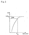
- FIG. 3 is a diagram showing the peak power-dependence of C/N in the first embodiment.
- PIGS. 4(a) and 4(b) are diagrams showing the results of calculation of the average transmittance and the transmittance ratio in the first embodiment.
- FIG. 5 is a section of a first information layer in the second embodiment.
- FIGS. 6(a) and 6(b) are diagrams showing the results of calculation of the average transmittance and the transmittance ratio in the second embodiment.
- FIG. 7 is a diagram showing the waveform of a reproduced signal from the second information recording layer in the first and second modes of implementation.
- FIG. 8 is an external view and a section of another optical information recording medium.
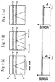
- FIGS. 9(a) -9(c) are schematic diagrams illustrating the procedure of a first optical measuring method.
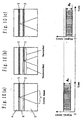
- FIG. 10(a)-10(c) are schematic diagrams illustrating the procedure of a second optical measuring method in accordance with the present invention.
- FIG. 11(a)-11(c) are schematic diagrams illustrating the procedure of a third optical measuring method.
- FIG. 1 and FIG. 2 are schematic diagrams of an optical information recording medium.
- FIG. 2 shows an optical disk having two information recording layers and a state in which it is irradiated with a laser beam.
- the optical disk 1 has a first information layer 2 positioned nearer to the light source and a second information layer 3 positioned farther from it.
- Each information layer is fabricated by forming a groove or a phase pit in a substrate 4 or 5 in advance and forming films of a dielectric layer, a recording layer, a reflecting layer and the like.
- the substrates are adhered with an ultraviolet ray-setting resin or the like to form an intermediate layer 6.
- the intermediate layer 6 having a groove or a phase pit and to combine, after forming each of the layers constituting the first information layer 2, the substrate 5 (also referred to as a cover layer).
- Flat transparent plates of glass, resin or the like is used for the substrates 4 and 5.
- they may be formed by dissolving a resin in a solvent coating, and drying.
- FIG. 2 is a sectional view showing an example of the configuration of the first information layer 2 constituting the nearer information layer in FIG. 1 as viewed from the incidence side of the laser beam.
- oxides such as SiO 2 , SiO, TiO 2 , MgO or GeO 2 , nitrides such as Si 3 N 4 , BN or AlN, sulfides such as ZnS or PbS or their mixtures can be used.
- a material undergoing a phase change between amorphous and crystalline states for instance an SbTe-based, InTe-based, GeTeSn-based, SbSe-based, TeSeSb-based, SnTeSe-based, InSe-based, TeGeSnO- based, TeGeSnAu-based, TeGeSnSb-based, or TeGeSb-based chalcogen compound, can be used.
- a Te-TeO 2 -based, Te-TeO 2 -Au-based, Te-TeO 2 -Pd-based or some other oxide-based material may also be used.
- any of these materials gives rise to a phase change between a crystalline state (corresponding to state (a)) and an amorphous state (corresponding to state (b)).
- the material may as well be an AgZn-based or InSb-based metallic compound giving rise to a phase change between one crystalline state (state (a)) and another crystalline state (state (b)).
- a metallic material such as Au, Ag, Al or Cu or a dielectric multi-layered film having a high reflectivity at a predetermined wavelength can be used.
- Films can be formed from these materials by vacuum vapor deposition or sputtering.
- the second information layer 3 may be in any form if it can detect optical changes of the reflected ray as information with a laser beam.
- it may be a multi-layered film containing a phase-change recording layer or a multi-layered film containing a magneto-optical recording layer or a dye layer. Or it may be in a form of being recorded as a phase pit in the substrate 4.
- a key point is that the transmittances of the first information layer 2 in two states before and after recording (recorded state and unrecorded (erased) state) are equalized by appropriately choosing the film thickness of each layer in the configuration described above, so that the intensity of the laser beam reaching the second information layer at the time of recording or re production can remain equal in any state. Further, the intensity of the laser beam reaching the second information layer should be sufficient for recording and reproduction.
- the following description will refer by way of example to a case in which the unrecorded (erased) part is in a crystalline state and the recorded part is in an amorphous state.
- the transmittance of the first information layer 2 can be figured out by a calculation known as the matrix method from the optical constant and film thickness of the material of each layer constituting the first information layer (the matrix method is described in, for instance, Hiroshi Kubota, Hado Kogaku (Wave Optics), Iwanami Shoten, 1971, Chapter 3).
- Table 1 shows an example of film thickness configuration of the first information layer 2 of a disk produced on a trial basis in this embodiment, its calculated transmittances in the amorphous state (T a ) and in the crystalline state (T c ), reflectivities in the amorphous state (R a ) and the crystalline state (R c ), absorption indices in the amorphous state (A a ) and the crystalline state (A c ), transmittance ratio between the amorphous state and the crystalline state (T c - T a )/T c , and average transmittance (T a + T c )/2.
- Each disk was fabricated in the following manner.
- a polycarbonate plate of 120 mm in diameter and 1.1 mm in thickness was used, and a spiral groove of 0.25 um in width, 0.32 um in pitch and 20 nm in depth was formed in its surface.
- the second information layer 3 was formed over the surface of this substrate 4, and a reflecting layer of AgPdCu (0.32-2.06i in optical constant) in a thickness of 100 nm, a dielectric layer of ZnS-SiO 2 (2.25-0.00i in optical constant) in 15 nm, a recording layer of GeSbTe (1.78-3.51i in the crystalline state and 3.31-2.29i in the amorphous state in optical constant 3.31-2.29 i) in 12 nm and a dielectric layer of ZnS-SiO 2 in 60 nm were formed in succession.
- a reflecting layer of AgPdCu 0.32-2.06i in optical constant
- a dielectric layer of ZnS-SiO 2 (2.25-0.00i in optical constant) in 15 nm
- the recording layer of the second information layer 3 was varied from the amorphous state into the crystalline state to initialize it by irradiation with a' laser beam, followed by the formation of the intermediate layer 6 to which the same groove shape as that in the substrate 4 was transcribed.
- a reflecting layer of AgPdCu was formed in a thickness of t b nm, a second dielectric layer of ZnS-SiO 2 in t 2 nm, a recording layer of GeSbTe in t a nm and a first dielectric layer of ZnS-SiO 2 in t 1 nm in succession.
- the recording layer of the first information layer 2 was initialized by varying it from the amorphous state to the crystalline state by irradiation with a laser beam.
- the substrate 5 consisting of polycarbonate was adhered with ultraviolet ray-setting resin.
- the total thickness of the adhesive portion and the substrate 5 was set to 0.1 mm.
- a recording/reproducing test was carried out using these six different disks. Each disk was turned at a linear speed of 5 m/s, either one of the information layers 2 and 3 of the disk was irradiated with a semiconductor laser beam of 405 nm in wavelength, narrowed down with an obj ective lens of 0.85 in numerical aperture (NA).
- NA numerical aperture
- the modulation code for recording and reproduction (8-16) modulation is used, and the modulated signals are turned into multi-pulse to generate the semiconductor laser.
- the mark length of 3T was set to be 0.20 ⁇ m.
- the optimal bias power was figured out as the bias power Pbo which would give the highest erasion rate by varying the bias power with the peak power kept constant, recording 3T signals and later overwriting 11T signals.
- Random signals were recorded in a half round area from the inner most circumference to the outermost circumference of the first information layer 2.
- the envelop change rate was satisfactory, no more than 5% for disks (1) through (4), but greater than that for disks (5) and (6).
- FIGS. 4 (a) and 4(b) are diagrams in which changes of the average transmittance (T a + T c ) /2 and of the transmittance ratio (T c - T a ) /T c are plotted where, by way of example, the thickness t a of the recording layer is set to 10 nm, the thickness t b of the reflecting layer is set to 10 nm and the film thickness t 1 of the first dielectric layer and the film thickness t 2 of the second dielectric layer are varied.
- the wavelength of the laser beam is set to 405 nm
- the film thicknesses of the upper dielectric and the lower dielectric are indicated in optical length with reference to the wavelength ( ⁇ ) of the laser beam.
- the film thickness of the dielectric layer which gives an average transmittance (T a + T c ) /2 of 40% or more in FIG. 4 (a) and the film thickness of the dielectric layer which gives an absolute value of the transmittance ratio (T c - T a ) /T c of 10% or less in FIG. 4(b) canbe made compatible with each other, the combination of the film thicknesses of these recording layer and reflecting layer will enable the first information layer 2 to be configured so as to make possible satisfactory recording and reproduction of information onto and out of the second information layer 3.
- Table 3 shows, when the film thickness t a of the recording layer is varied from 2 to 32 nm and the film thickness t b of the reflecting layer, from 2 to 36 nm, whether or not a first information layer 2 that has potential to keep the average transmittance (T a + T c ) /2 at or above 40% and the absolute value of the transmittance ratio (T c - T a )/T c at or below 10% can be configured.
- ⁇ marks indicate that the pertinent film thicknesses t a and t b can keep the average transmittance at or above 40% and the absolute value of the transmittance ratio at or below 10%.
- ⁇ marks indicate that, whatever t a and t b may be chosen, there is no possibility to keep the average transmittance at or above 40% and the absolute value of the transmittance ratio at or below 10%. In other words, there is no area whatsoever in which the average transmittance is from 40 to 50% and the transmittance ratio is from -10 to +10% in FIGS. 4(a) and 4(b).
- Table 3 also shows that a configuration Meeting the above-stated requirements of the average transmittance and the transmittance ratio can be obtained with a configuration in which both the recording layer and the reflecting layer are thin.
- the layers which have optical absorption in the first information layer 2 are mainly the recording layer and the reflecting layer. It can further be the that, since the recording layer is nearer than the reflecting layer as viewed from the light source side, the absorption index of the recording layer is greater than the absorption index of the reflecting layer and that increasing the film thickness of the recording layer can influence the transmittance more than increasing the film thickness of the reflecting layer.
- n a + k a ⁇ n c + k c it tends to be easier to obtain a configuration in which T c and T a are substantially equalized by having A a ⁇ A c as the absorption indices of the recording films and R a > R c as the reflectivities.
- the recording layer in the previous described embodiment has a relationship n a +k a >n c +k c it is easier to obtain a configuration in which T c and T a are substantially equalized by having A a > A c as the absorption indices of the recording films and R a ⁇ R c as the reflectivities.
- the optical information recording medium in this embodiment by reducing the absolute value of the transmittance ratio (T c - T a ) /T c to 100 or less and raising the average transmittance (T a + T c ) /2 of the first information layer 2 to 40% or more, sufficient intensity of the laser beam is enabled to reach the second information layer 3, and information can be accurately recorded and reproduced irrespective of whether or not information is recorded on the first information layer 2.
- FIG. 5 is a sectional view showing an example of configuration of the first information layer 2, which constitutes the nearer information layer in FIG. 1 as viewed from the incidence side of the laser beam.
- This mode differs from the first embodiment in that a third dielectric layer 13 is provided over the reflecting layer 12.
- FIG. 6 is a diagram in which changes of the average transmittance (T a + T c ) /2 and of the transmittance ratio (T c - T a )/T c are plotted where the thickness of the recording layer is set to 10 nm, the thickness of the reflecting layer is set to 10 nm, the thickness of the third dielectric layer is set to 10 nm and the film thicknesses of the first dielectric layer and the second dielectric layer are varied. To compare FIG.
- the provision of the third dielectric layer has expanded the area in which the absolute value of the transmittance ratio (T c - T a )/T c is 10% or less. Further, if the thickness of the third dielectric layer is selected properly, it will also be possible to enhance the average transmittance. Thus, this has the role of increasing the freedom of configuration of the first information layer 2.
- Table 4 shows an example of film thickness configuration of the first information layer 2 of a disk produced on a trial basis in this embodiment, its calculated transmittances in the amorphous state (T a ) and in the crystalline state (T c ), reflectivities in the amorphous state (R a ) and the crystalline state (R a ), absorption indices in the amorphous state (A a ) and in the crystalline state (A c ), transmittance ratio between the amorphous state and the crystalline state (T c - T a )/T c , and average transmittance (T a + T c )/2.
- disks differing in transmittance ratio and average transmittance of the first information layer 2 were prepared by varying the thickness t a of the recording layer, the thickness t b of the reflecting layer, the thickness t 1 of the first dielectric layer, the thickness t 2 of the second dielectric layer, and the thickness t 3 of the third dielectric layer.
- the disks were prepared in a similar way to those in the first embodiment, differing from the first embodiment in the following respects.
- the first information layer 2 there were formed in succession a third dielectric layer of ZnS-SiO 2 to t 3 nm, a reflecting layer of AgPdCu to t b nm, a second dielectric layer of ZnS-SiO 2 to t 2 nm, a recording layer of GeSbTe to t a nm, and a first dielectric layer of ZnS-SiO 2 to t 2 nm.
- each disk was turned at a linear speed of 5 m/s, either one of the information layers 2 and 3 of the disk was irradiated with a semiconductor laser beam of 405 nm in wavelength, narrowed down with an objective lens of 0.85 in numerical aperture (NA).
- NA numerical aperture
- the film thickness conditions to enable the average transmittance (T a + T c )/2 to be raised to 40% or above and the absolute value of the transmittance ratio (T c - T a ) /T c to be reduced to 10% or below in the configuration shown in FIG. 5 were checked in detail by calculation.
- Table 6 shows, when the film thickness t a of the recording layer is varied from 2 to 32 nm and the film thickness t b of the reflecting layer, from 2 to 36 nm, whether or not a first information layer 2 that has potential to keep the average transmittance (T a + T c ) /2 at or above 40% and the absolute value of the transmittance ratio (T c - T a ) /T c at or below 10% can be configured.
- Table 7 shows a case in which the film thicknesses of the recording layer and of the reflecting layer were similarly varied and the film thickness t 3 of the third dielectric layer was set to 30 nm; Table 8, a similar case in which the thickness was 50 nm, and Table 9, another case in which the thickness was 70 nm.
- the optical information recording medium in this embodiment as well, if so configured as to reduce the absolute value of the transmittance ratio (T c - T a )/T c to 10% or below and raise the average transmittance (T a + T c )/2 of the first information layer 2 to 40% or above, sufficient intensity of the laser beam will be enabled to reach the second information layer 3, and information can be accurately recorded and reproduced irrespective of whether or not information is recorded on the first information layer 2.
- FIGS. 9 are schematic diagrams illustrating such a first optical measuring method, in which the upper part comprises schematic sections showing how the the upper part comprises schematic sections showing how the laser beam irradiates each information layer and the lower part, a waveform diagram of a reproduced signal obtained from the laser beam reflected by the second information layer.
- irradiation with a laser beam is carried out with focus on the second information layer. It is desirable for the irradiating position in this process to be set in a so-called still state, in which a return to the original position takes place, for instance, at every full turn, because in this way comparison with the result of measurement at the next step is facilitated.
- the reflected intensity is converted into an electric current or a voltage by a photodetector for signal reproduction or the like, and observed as a reproduced waveform of a substantially direct current as shown in the lower part of FIG. 9(a).
- the actual waveform is more or less uneven because its is fluctuated by the reflectivity of the optical disk or the like, it can be considered a D. C. waveform when averaged over time.
- the zero level of the longitudinal axis of this diagram represents the output of the photodetector when the optical disk is removed from the optical path of the laser beam. Therefore, level S a shown in the diagram represents the reflected intensity in a state in which nothing is recorded on the first information layer.
- the recording range is designated to include the whole area which, when a laser beam is focused on the second information layer, the laser beam passes the first information layer. If the wavelength of the laser beam is 405 nm, the NA of the objective lens is 0.85, the thickness of the middle layer is 30 ⁇ m, and the refractive index of the middle layer is 1.60, the diameter of the laser beam in the first information layer will be approximately 37.6 ⁇ m. With this diameter and the eccentricity between the first and second layers taken into consideration, the required recording range may be 200 ⁇ m or so.
- irradiation with the laser beam is carried out with focus on the second information layer through the first information layer on which random signals or monotone signals are recorded as shown in the upper part of FIG. 9(c). It is desirable with a view to greater accuracy of measurement for the irradiating position then to coincide with the track measured at step 1.
- the reflected intensity is observed as a reproduced waveform of a substantially direct current as shown in the lower part of FIG. 9(c).
- Level S b shown in the diagram represents the reflected intensity in a recorded of the first information layer. This diagram shows a case in which the transmittance is lower in the recorded state than in the unrecorded state.
- FIGS. 10 are schematic diagrams showing the procedure of a second optical measuring method, in which the upper part comprises schematic sections showing how the laser beam irradiates each information layer and the lower part, a waveform diagram of a reproduced signal obtained from the laser beam reflected by the second information layer.
- irradiation with a laser beam is carried out with focus on the second information layer, random or monotone signals are recorded on a predetermined track of the second information layer. Then the signals recorded on that track are irradiated with a laser beam of the reproduction level, converted into an electric current or a voltage by a photodetector or the like, and observed as an envelope waveform having a fixed amplitude as shown in the lower part of FIG. 10(a).
- the amplitude A 1 shown in the diagram represents the reproduced signal amplitude in a state in which nothing is recorded on the first information layer.
- the random signals or monotone signals are recorded in a position on the first information layer immediately below the position in which A 1 was measured at step 1 as shown in the upper part of FIG. 10(b).
- the recording range is the same as according the first optical measuring method.
- irradiation with the laser beam is carried out with focus on the second information layer through the first information layer on which random signals or monotone signals are recorded as shown in the upper part of FIG. 10(c).
- the irradiating position then is caused to coincide with the track measured at step 1.
- the reproduced signals are observed as an envelope waveform having a fixed amplitude as shown in the lower part of FIG. 10(c).
- the amplitude A 2 shown in the diagram represents the reproduced signal amplitude in the recorded state of the first information layer.
- This diagram shows a case in which the transmittance is lower in the recorded state than in the unrecorded state of the first information layer.
- the transmittance ratio (T c - T a ) /T c between the unrecorded state and the recorded state of the first information layer can be figured out.
- the tolerance of the transmittance difference that is measured can be suppressed to 2/100, making possible, sufficiently accurate measurement.
- /T c ) between the recorded state and unrecorded state of the first information layer can be obtained in such manner that the differences A 1 , and A 2 . between the zero level and upper envelope of the modulation amplitude are detected and the S, is replaced with A 1 , and S b is replaced with A 2 , in the calculation described in the first optical measuring method description.
- the transmittance ratio can be easily figured out through Equation (1). Since the desirable transmittance ratio of the first information layer is 10% or less, if Equation (1) is used, it will be satisfactory for S a and S b that are obtained by the first optical measuring method to meet the requirement of: 0 ⁇ 1 - S b / S a 1 / 2 ⁇ 0.1 ⁇ ⁇ Or it will be satisfactory for A 1 and A 2 obtained by the second optical measuring method to meet the requirement of: 0 ⁇ 1 - A 2 / A 1 1 / 2 ⁇ 0.1 ⁇ ⁇ .
- the first information layer 2 is configured of four layers as shown in FIG. 2 or five layers as shown in FIG. 5 in the media of the above-described modes of implementation
- a multi-layered configuration having an interface layer between each adjacent pair of these layers can also be used if it is so structure as to satisfy the above-stated conditions regarding the transmittance ratio and/or the average transmittance.
- Some other configurations than those illustrated in FIG. 2 and FIG. 5, such as having no reflecting layer, can be used as well.
- the materials of the individual layers limited to those used in these modes of implementation.
- each optical disk in the above-described modes of implementation has two information layers
- This synthesized transmittance is the product of the transmittances of the information layers. There exist, depending on the combination of the recorded and unrecorded states of different layers, a state in which the synthesized transmittance is at its minimum (this transmittance is represented by T min ) and a state in which it is at its maximum (this transmittance is represented by T max ).
- the configuration can be: 0 ⁇
- T c is the synthesized transmittance when every one of the plurality of information layers is in an unrecorded state.
- the S/N ratio of the reproduction circuit should be enhanced in order to ensure adequate signal quality.
- the medium to be detected can has three or more information layers.
- maximum change of the transmittance for the nearer plurality of the information layers can be detected by detecting the respective reflection amounts of case (a) and case (b).
- the case (a) means that the'synthesized transmittance of the plurality of information layers positioned nearer than the farthest information layer from the incidence side of said laser beam, is minimum.
- the case (b) means that the synthesized transmittance of the plurality of information layers positioned nearer than the farthest information layer from the incidence side of said laser beam, is maximum.
- the transmittance ratio is calculated in the step 4 on the basis of the measured S a (or A 1 ,A 1 ') and S b (or A 2 ,A 2 '). But instead of it, by detecting the changing of such measured values the goodness of the change of the transmittance of the nearer positioned information layer can be easily obtained without measuring the transmission foctor ratio.
- the S a (or A 1 ,A 1' ) and S b (or A 2 ,A 2' ) vary because of the unevenness of the reflectivities etc. of the disk, however the changing of the transmittance of the nearer information layer effect largely against the varying of the parameters.
- modulation system and recording density usable in the above-described modes of implementation are not limited to those described above, but it goes without saying that can be in any appropriate forms for the medium itself or the recording/reproducing apparatus.
- the optical information recording medium can cause sufficient intensity of the laser beam to reach the information layer farther inside, and can accurately record and reproduce onto and out of the farther information layer irrespective of whether or not any information is recorded on the nearer information layer.
- the optical measuring method of the present invention can easily detect the changing of the transmittance of the nearer information layer in such conditions of recorded or unrecorded.
Landscapes
- Chemical & Material Sciences (AREA)
- General Health & Medical Sciences (AREA)
- Life Sciences & Earth Sciences (AREA)
- Health & Medical Sciences (AREA)
- Analytical Chemistry (AREA)
- Biochemistry (AREA)
- Physics & Mathematics (AREA)
- General Physics & Mathematics (AREA)
- Immunology (AREA)
- Pathology (AREA)
- Inorganic Chemistry (AREA)
- Optical Record Carriers And Manufacture Thereof (AREA)
- Optical Recording Or Reproduction (AREA)
- Optical Head (AREA)
Description
- The present invention relates to an optical measuring method for determining a change in transmittance in a first information layer of an optical information recording medium having two or more information layers.
- In recent years, optical disks, optical cards and optical tapes have been proposed and developed as media for optically recording information. Above all, optical disks are attracting note as media capable of recording and reproducing information in large capacity and in high density.
- One of the erasable optical disk types is a phase change type optical disk. The recording film for use in the phase change type optical disk takes on either an amorphous state or a crystalline state depending on the conditions of heating or cooling with a laser beam, and the two states are reversible between each other. The optical constant of the recording film in different between the amorphous state and the crystalline state. In the phase change type optical disk, one or the other or the two states is selectively formed in the recording film according to information signals, and the resultant optical change (i.e. the change in transmittance or reflectivity) is utilized for recording or reproducing the information signals. In order to achieve the two states, the information signals are recorded by the following method.
- When the recording film of the optical disk is irradiated in a pulse form with power for raising the temperature of the recording film above its melting point (hereinafter referred as peak power), the molten portion is quickly cooled with the passage of the laser beam to present a record mark of the amorphous state. Or when the recording film is irradiated with a converted laser beam of an intensity to raise the temperature of the recording film above its crystallization temperature but not over the melting point (hereinafter referred as bias power), the irradiated portion of the recording film turns into the crystalline state.
- In addition, a keen requirement has emerged in recent years for higher density of optical disks. In connection with that, there has been proposed a multi-layered recording medium having two or more layers in the thickness direction of the disk wherein information can be recorded onto or reproduced out of each information layer.
- However, when recording is to be done onto an information layer farther inside from the laser incidence side by the conventional method, there is a fear that the farther inside information layer is affected by the nearer information layer.
- For instance, depending on whether or not any signal is recorded in a recording/reproducing area of an information recording layer, the transmittance of that layer differs. Accordingly there is a problem that, when recording is to be done on a farther information layer, the intensity of the laser beam reaching the farther information layer varies with the ratio between the amorphous area and the crystalline area in the laser spot on the nearer information recording layer, making it impossible to perform accurate recording.
- A further problem is that, when data on the farther information layer are to be reproduced, the change in the transmittance depending on the recording state of the nearer information layer invites deterioration in the quality of reproduced signals.
- Document
US-B1-6221455 shows an optical system to record or reproduce information signals for a multi-layered optical disc. In this optical system, the laser light radiated from a semiconductor laser is collimated by a collimator lens. The collimated light traverses a beam splitter, a quarter wave plate and an objective lens to form a beam spot on the disc surface. The reflected light from the disc surface again traverses the objective lens and the quarter wave plate to fall on the beam splitter. The light is then reflected by a focussing servo system and received by a photodiode via a light converging lens and a cylindrical lens. - An object of the present invention is to provide for an optical measuring method to determine a change in transmittance in the first information layer of an optical information recording medium having two information layers. The first information layer having a recording layer varying between two optically detectable states.
- This is achieved by the features as set forth in the independent claims. Further advantageous embodiments of the present invention are set forth in the dependent claims.
- A first optical measuring method whereby a laser beam is converged on an optical information recording medium having two information layers, converged irradiation of the laser beam onto any of said information layers causing information signals to be recorded or reproduced, wherein
an information layer positioned nearer than the farthest information layer from the incidence side of said laser beam has a recording layer varying between two optically detectable states, and said laser beam reflected by any of said information layers is received by a photodetector to measure changes in transmittance, comprising: - a step of measuring with said photodetector the intensity of said laser beam coming out of said optical information recording medium when the area transmitting said laser beam in the recording layer contained in said nearer positioned information layer is in state (a), the intensity being represented by Sa, wherein
- said laser beam has first been transmitted by said nearer positioned information layer, then been reflected by the farthest information layer, and again been transmitted by said nearer positioned information layer so that the laser beam comes out of said optical information recording medium,
- a step of measuring with said photodetector the intensity of said laser beam coming out of said optical information recording medium when the area transmitting said laser beam in the recording layer contained in said nearer positioned information layer is in state (b), the intensity being represented by Sb, wherein
- said laser beam has first been transmitted by said nearer positioned information layer, then been reflected by the farthest information layer, and again been transmitted by said nearer positioned information layer so that the laser beam comes out of said optical information recording medium, and
- a step of deriving a change in the transmittance of said nearer positioned information layer on the basis of said Sa and Sb.
- A second optical measuring method whereby a laser beam is converged on an optical information recording medium having three or more information layers, converged irradiation of the laser beam onto any of said information layers causing information signals to be recorded or reproduced, wherein
a plurality of information layers positioned nearer than the farthest information layer from the incidence side of said laser beam have a recording layer varying between two optically detectable states, and said laser beam reflected by any of said information layers is received by a photodetector to measure changes in transmittance,
case (a) is such case that a synthesized transmittance of said plurality of information layers is minimum value within the synthesized transmittances which are derived from combinations of saidvarious states of the respective recording layers, and
case (b) is such case that a synthesized transmittance of said plurality of information layers is maximum value within the synthesized transmittances which are derived from combinations of said various states of the respective recording layers, and comprising: - a step of measuring with said photodetector the intensity of said laser beam coming out of said optical Information recording medium when the combination of the states of the recording layers of said nearer plurality of the information layers is in the case (a), the intensity being represented by Sa, wherein said laser beam has first been transmitted by said nearer plurality of the information layers, then been reflected by a predetermined information layer located farther inside than the information layer that has transmitted the beam, and again been transmitted by said nearer plurality of the information layers so that the laser beam comes out of said optical information recording medium,
- a step of measuring with said photodetector the intensity of said laser beam coming out of said optical information recordingmediumwhen the combination of the states of the recording layers of said nearer plurality of the information layers is in the case (b), the intensity being represented by Sb, wherein said laser beam has first been transmitted by said nearer plurality of the information layers, then been reflected by the farthest information layer, and again been transmitted by said nearer plurality of the information layers so that the laser beam comes out of said optical information recording medium, and
- a step of deriving a change in the transmittance of said nearer plurality of the information layers on the basis of said Sa and Sb.
- A third optical measuring method whereby a laser beam is converged on an optical information recording medium having two information layers, converged irradiation of the laser beam onto any of said information layers causing information signals to be recorded or reproduced, wherein
an information layer positioned nearer than the farthest information layer from the incidence side of said laser beam has a recording layer varying between two optically detectable states, and said laser beam reflected by any of said information layers is received by a photodetector to measure changes in strength of the laser beam, comprising: - a step of measuring with said photodetector the intensity of said laser beam coming out of said optical information recording medium when the area transmitting said laser beam in the recording layer contained in said nearer positioned information layer is in state (a), the intensity being represented by Sa, wherein
- said laser beam has first been transmitted by said nearer positioned information layer, then been reflected by the farthest information layer, and again been transmitted by said nearer positioned information layer so that the laser beam comes out of said optical information recording medium,
- a step of measuring with said photodetector the intensity of said laser beam coming out of said optical information recording medium when the area transmitting said laser beam in the recording layer contained in said nearer positioned information layer is in state (b), the intensity being represented by Sb, wherein
- said laser beam has first been transmitted by said nearer positioned information layer, then been reflected by the farthest information layer, and again been tranamittedby said nearer positioned information layer so that the laser beam comes out of said optical information recording medium, and
- a/step of deriving a change in the strength of the laser beam on the basis of said Sa and Sb.
- A fourth optical measuring method whereby a laser beam is converged on an optical information recording medium having three or more information layers, converged irradiation of the laser beam onto any of said information layers causing information signals to be recorded or reproduced, wherein
a plurality of information layers positioned nearer than the farthest information layer from the incidence side of said laser beam have a recording layer varying between two optically detectable states, and said laser beam reflected by any of said information layers is received by a photodetector to measure changes in the strength of the laser beam,
case (a) is such case that a synthesized transmittance of said plurality of information layers is minimum value within the synthesized transmittances which are derived from combinations of said various states of the respective recording layers, and
case (b) is such case that a synthesized transmittance of said plurality of information layers is maximum value within the synthesized transmittances which are derived from combinations of said various states of the respective recording layers, and comprising: - a step of measuring with said photodetector the intensity of said laser beam coming out of said optical information recording medium when the combination of the states of the recording layers of said nearer plurality of the information layers is in the case (a), the intensity being represented by Sa, wherein said laser beam has first been transmitted by said nearer plurality of the information layers, then been reflected by a predetermined information layer located farther inside than the information layer that has transmitted the beam, and again been transmitted by said nearer plurality of the information layers so that the laser beam comes out of said optical information recording medium,
- a step of measuring with said photodetector the intensity of said laser beam coming out of said optical information recording medium when the combination of the states of the recording layers of said nearer plurality of the information layers is in the case (b), the intensity being represented by Sb, wherein said laser beam has first been transmitted by said nearer plurality of the information layers, then been reflected by the farthest information layer, and again been transmitted by said nearer plurality of the information layers so that the laser beam comes out of said optical information recording medium, and
- a step of deriving a change in the strength of the laser beam on the basis of said Sa and Sb.
- By the third and fourth measuring methods the amount of the change of the transmittance of the nearer positioned information layer can be easily obtained without measuring the transmission foctor.
- A fifth optical measuring method whereby a laser beam is converged on an optical information recording medium having two information layers, converged irradiation of the laser beam onto any of said information layers causing information signals to be recorded or reproduced, wherein an information layer positioned nearer than the farthest information layer from the incidence side of said laser beam has a recording layer varying between two optically detectable states, and said laser beam reflected by any of said information layers is received by a photodetector to measure changes in transmittance, comprising:
- a step of measuring with said photodetector a modulation amplitude of said laser beam coming out of said optical information recording medium when the area transmitting said laser beam in the recording layer contained in said nearer positioned information layer is in state (a), the modulation amplitude being represented by A1, wherein the laser beam has first been transmitted by said nearer positioned information layer then been modulated by said information signals recorded on the farthest information layer, and again been transmitted by said nearer positioned information layer so that the laser beam comes out of said optical information recording medium,
- a step of measuring with said photodetector the modulation amplitude of said laser beam coming out of said optical information recording medium when a part of or the whole of the area transmitting said laser beam in the recording layer contained in said nearer positioned information layer is in state (b), the modulation amplitude being represented by A2, wherein the laser beam has first been transmitted by said nearer positioned information layer, then been modulated by said information signals recordedon the farthest information layer, and again been transmitted by said nearer positioned information layer so that the laser beam comes out of said optical information recording medium, and
- a step of deriving a change in the transmittance of said nearer positioned information layer on the basis of said A1 and A2.
- A sixth optical measuring method whereby a laser beam is converged on an optical information recording medium having three or more information layers, converged Irradiation of the laser beam onto any of said information layers causing information signals to be recorded or reproduced, wherein a plurality of the information layers positioned nearer than the farthest information layer from the incidence side of said laser beam have a recording layers each varying between two optically detectable states, and said laser beam reflected by any of said information layers is received by a photodetector to measure changes in transmittance, and
case (a) is such case that a synthesized transmittance of said plurality of information layers is minimum value within the synthesized transmittances which are derived from combinations of said various states of the respective recording layers, and
case (b) is such case that a synthesized transmittance of said plurality of information layers is maximum value within the synthesized transmittances which are derived from combinations of said various states of the respective recording layers, and comprising: - a step of measuring with said photodetector a modulation amplitude of said laser beam coming out of said optical information recording medium when the combination of the states of the recording layers of said nearer plurality of the information layers is in the case (a), the modulationamplitude being represented by A1, wherein the laser beam has first been transmitted by said nearer plurality of the information layers, then been modulated by said information signals recorded on a predetermined information layer located farther inside than the information layer that has transmitted the beam, and again been transmitted by said nearer plurality of the information layers so that the laser beam comes out of said optical information recording medium,
- a step of measuring with said photodetector a modulation amplitude of said laser beam coming out of said optical information recording medium when the combination of the states of the recording layers of said nearer plurality of the information layers is in the case (b), the modulation amplitude being represented by A2, wherein the laser beam has first been transmitted by said nearer plurality of the information layers, then been modulated by said information signals recorded on the farthest information layer, and again been transmitted by said nearer plurality of the information layers so that the laser beam comes out of said optical information recording medium, and
- a step of deriving a change In the transmittance of said nearer positioned information layer on the basis of said A1 and A2.
- A seventh optical measuring method whereby a laser beam is converged on an optical information recording medium having two information layers, converged irradiation of the laser beam onto any of said information layers causing information signals tobe recorded or reproduced, wherein an information layer positioned nearer than the farthest information layer from the incidence aide of said laser beam has a recording layer varying between two optically detectable states, and said laser beam reflected by any of said information layers is received by a photodetector to measure changes in a modulation amplitude of the laser beam, comprising:
- a step of measuring with said photodetector a modulation amplitude of said laser beam coming out of said optical information recording medium when the area transmitting said laser beam in the recording layer contained in said nearer positioned information layer is in state (a), the modulation amplitude being represented by A1, wherein the laser beam has first been transmitted by said nearer positioned information layer, then been modulated by said in formation signals recorded on the farthest information layer, and again been transmitted by said nearer positioned information layer so that the laser beam comes out of said optical information recording medium,
- a step of measuring with saidphotodetector the modulation amplitude of said laser beam coming out of said optical information recording medium when a part of or the whole of the area transmitting said laser beam in the recording layer contained in said nearer positioned information layer is in state (b), the modulation amplitude being represented by A2, wherein the laser beamhas first been transmitted by said nearer positioned information layer, then been modulated by said information signals recorded on the farthest information layer and again been transmitted by said nearer positioned information layer so that the laser beam comes out of said optical information recording medium, and
- a step of deriving a change in the modulation amplitude of the laser beam on the basis of said A1 and A2.
- An eighth optical measuring method whereby a laser beam is converged on an optical information recording medium having three or more information layers, converged irradiation of the laser beam onto any of said information layers causing information signals to be recorded or reproduced, wherein a plurality of the information layers positioned nearer than the farthest information layer from the incidence side of said laser beam have a recording layers each varying between two optically detectable states, and said laser beam reflected by any of said information layers is received by a photodetector to measure changes in a modulation amplitude of the laser beam, and
case (a) is such case that a synthesized transmittance of said plurality of information layers is minimum value within the synthesized transmittances which are derived from combinations of said various states of the respective recording layers, and
case (b) is such case that a synthesized transmittance of said plurality of information layers is maximum value within the synthesized transmittances which are derived from combinations of said various states of the respective recording layers, and comprising: - a step of measuring with said photodetector a modulation amplitude of said laser beam coming out of said optical information recording medium when the combinationof the states of the recording layers of said nearer plurality of the information layers is in the case (a), the modulation amplitude being represented by A1, wherein the laser beam has first been transmitted by said nearer pluralityof the information layers, then been modulated by said information signals recorded on a predetermined information layer located farther inside than the information layer that has transmitted the beam, and again been transmitted by said nearer plurality of the information layers so that the laser beam comes out of said optical information recording medium,
- a step of measuring with said photodetector a modulation amplitude of said laser beam coming out of said optical information recording medium when the combination of the states of the recording layers of said nearer plurality of the information layers is in the case (b), the modulation amplitude being represented by A2, wherein the laser beam has first been transmitted by said nearer plurality of the information layers, then been modulated by said information signals recorded on the farthest information layer, and again been transmitted by said nearer plurality of the information layers so that the laser beam comes out of said optical information recording medium, and
- a step of deriving a change in the modulation amplitude of the laser beam on the basis of said A1 and A2
- By the seventh and eighth measuring methods the amount of the change of the transmittance of the nearer positioned information layer can be easily obtained without measuring the transmission foctor.
- The 9-th optical measuring method is based on the seventh or eighth method, wherein
the difference A1, between a zero level and upper envelope of the modulation amplitude is measured instead of the modulation amplitude A1 of the laser beam,
the difference A2, between a zero level and upper envelope of the modulation amplitude is measured instead of the modulation amplitude A2 of the laser beam, and
the change in the upper envelope of the modulation amplitude of the laser beam is detected on the basis of the A1, and A2, instead of that the change in the modulation amplitude of the laser beam is detected on the basis of the A1 and A2. - The 10-th optical measuring method is based on the fifth method whereby, when the area in which said laser beam transmits of the recording layer contained in the nearer information layer is in state (b), after recording information signals on the farthest information layer, the modulation amplitude A2 is measured.
- The 11-th optical measuring method is based on any of the first, third, fifth, seventh or tenth method wherein said state (a) is a crystalline state and said state (b) is an amorphous state.
- The 12-th optical measuring method is based on the 11-th method wherein the recording layer of said nearer positioned information layer - is, when said Sb Or A2 or A2' is be measured, in a state consisting of many recording marks in an amorphous state and crystalline portions around them
- The 13-th optical measuring method is based on any of the first, third, fifth, seventh or tenth method said state (a) is an amorphous state and said state (b) is a crystalline state.
- The 14-th optical measuring method is based on the 13-th method wherein the recording layer of said nearer positioned information layer is, when said Sb or A2 or A2' is be measured, in a state consisting of many recording marks in a crystalline state and amorphous portions around them.
- An optical information recording medium having a configuration of:

where α is the ratio of the area of said recording mark portion to the area where said laser beam is transmitted when said Sb used in the optical measuring method described in the first method is measured. - An optical information recording medium having a configuration of:

where α is the ratio of the area of said recording mark portion to the area where said laser beam is transmitted when said A2 used in the optical measuring method described in the fifth method is measured. - FIG. 1 is an external view and a section of an optical information recording medium.
- FIG. 2 is a section of a first information layer in the first embodiment.
- FIG. 3 is a diagram showing the peak power-dependence of C/N in the first embodiment.
- PIGS. 4(a) and 4(b) are diagrams showing the results of calculation of the average transmittance and the transmittance ratio in the first embodiment.
- FIG. 5 is a section of a first information layer in the second embodiment.
- FIGS. 6(a) and 6(b) are diagrams showing the results of calculation of the average transmittance and the transmittance ratio in the second embodiment.
- FIG. 7 is a diagram showing the waveform of a reproduced signal from the second information recording layer in the first and second modes of implementation.
- FIG. 8 is an external view and a section of another optical information recording medium.
- FIGS. 9(a) -9(c) are schematic diagrams illustrating the procedure of a first optical measuring method.
- FIG. 10(a)-10(c) are schematic diagrams illustrating the procedure of a second optical measuring method in accordance with the present invention.
- FIG. 11(a)-11(c) are schematic diagrams illustrating the procedure of a third optical measuring method.
-
- 1
- Optical disk
- 2
- First information layer
- 3
- Second information layer
- 4, 5
- substrates
- 6
- Middle layer
- 7
- Objective lens
- 8
- Laser beam
- 9
- First dielectric layer
- 10
- Second dielectric layer
- 11
- Recording layer
- 12
- Reflecting layer
- 13
- Third dielectric layer
- Embodiments will be described in more specific terms below with reference to the drawings.
- FIG. 1 and FIG. 2 are schematic diagrams of an optical information recording medium.
- A section of an
optical disk 1 in FIG. 1 is shown in FIG. 2. FIG. 2 shows an optical disk having two information recording layers and a state in which it is irradiated with a laser beam. Theoptical disk 1 has afirst information layer 2 positioned nearer to the light source and asecond information layer 3 positioned farther from it. Each information layer is fabricated by forming a groove or a phase pit in asubstrate intermediate layer 6. - Alternatively, it is also acceptable to form, after forming each of the layers constituting the
second information layer 3 in thesubstrate 4 in which a groove or a phase pit is already formed, theintermediate layer 6 having a groove or a phase pit and to combine, after forming each of the layers constituting thefirst information layer 2, the substrate 5 (also referred to as a cover layer). - Flat transparent plates of glass, resin or the like is used for the
substrates - FIG. 2 is a sectional view showing an example of the configuration of the
first information layer 2 constituting the nearer information layer in FIG. 1 as viewed from the incidence side of the laser beam. - For a first
dielectric layer 9 and asecond dielectric layer 10 over thesubstrate 5, oxides such as SiO2, SiO, TiO2, MgO or GeO2, nitrides such as Si3N4, BN or AlN, sulfides such as ZnS or PbS or their mixtures can be used. - As a recording film material of a
recording layer 11, a material undergoing a phase change between amorphous and crystalline states, for instance an SbTe-based, InTe-based, GeTeSn-based, SbSe-based, TeSeSb-based, SnTeSe-based, InSe-based, TeGeSnO- based, TeGeSnAu-based, TeGeSnSb-based, or TeGeSb-based chalcogen compound, can be used. A Te-TeO2-based, Te-TeO2-Au-based, Te-TeO2-Pd-based or some other oxide-based material may also be used. Any of these materials gives rise to a phase change between a crystalline state (corresponding to state (a)) and an amorphous state (corresponding to state (b)). The material may as well be an AgZn-based or InSb-based metallic compound giving rise to a phase change between one crystalline state (state (a)) and another crystalline state (state (b)). - As a reflecting
layer 12, a metallic material such as Au, Ag, Al or Cu or a dielectric multi-layered film having a high reflectivity at a predetermined wavelength can be used. - Films can be formed from these materials by vacuum vapor deposition or sputtering.
- To add, the
second information layer 3 may be in any form if it can detect optical changes of the reflected ray as information with a laser beam. Similarly to thefirst information layer 2, it may be a multi-layered film containing a phase-change recording layer or a multi-layered film containing a magneto-optical recording layer or a dye layer. Or it may be in a form of being recorded as a phase pit in thesubstrate 4. - A key point is that the transmittances of the
first information layer 2 in two states before and after recording (recorded state and unrecorded (erased) state) are equalized by appropriately choosing the film thickness of each layer in the configuration described above, so that the intensity of the laser beam reaching the second information layer at the time of recording or re production can remain equal in any state. Further, the intensity of the laser beam reaching the second information layer should be sufficient for recording and reproduction. Incidentally, the following description will refer by way of example to a case in which the unrecorded (erased) part is in a crystalline state and the recorded part is in an amorphous state. - The transmittance of the
first information layer 2 can be figured out by a calculation known as the matrix method from the optical constant and film thickness of the material of each layer constituting the first information layer (the matrix method is described in, for instance, Hiroshi Kubota, Hado Kogaku (Wave Optics), Iwanami Shoten, 1971, Chapter 3). - Table 1 shows an example of film thickness configuration of the
first information layer 2 of a disk produced on a trial basis in this embodiment, its calculated transmittances in the amorphous state (Ta) and in the crystalline state (Tc), reflectivities in the amorphous state (Ra) and the crystalline state (Rc), absorption indices in the amorphous state (Aa) and the crystalline state (Ac), transmittance ratio between the amorphous state and the crystalline state (Tc - Ta)/Tc, and average transmittance (Ta + Tc)/2.[Table 1] Disk ta [nm] tb [nm] t1 [nm] t2 [nm] Rc [%] Ra [%] Tc [%] Ta [%] Ac [%] Aa [%] Transmittance ratio [%] Average transmittance [%] (1) 6 6 45 12 6 0 48 47 42 49 2 47 (2) 10 12 40 45 3 9 46 41 42 41 10 44 (3) 8 20 40 68 25 18 40 41 18 23 -5 41 (4) 14 10 22 40 15 23 32 28 - - 13 30 (5) 14 30 68 12 34 9 5 7 - - -41 6 (6) 12 26 62 60 19 31 29 23 - - 21 26 - In this embodiment, to equalize the intensities of the laser beam reaching the second information layer at the time of recording or reproduction between the amorphous state and the crystalline state, the smaller the absolute value of the transmittance ratio (Tc - Ta)/Tc, the more desirable. It is also desirable to maximize the average transmittance (Ta + Tc)/2 to secure a sufficient level of the intensity of the laser beam reaching the second information layer for recording and reproduction. In this embodiment, as shown in Table 1, six kinds of disks differing in transmittance ratio and average transmittance of the
first information layer 2 were prepared by varying the thickness ta of the recording layer, the thickness tb of the reflecting layer, the thickness t1 of the first dielectric layer and the thickness t2 of the second dielectric layer. - Each disk was fabricated in the following manner. As the
substrate 4, a polycarbonate plate of 120 mm in diameter and 1.1 mm in thickness was used, and a spiral groove of 0.25 um in width, 0.32 um in pitch and 20 nm in depth was formed in its surface. Thesecond information layer 3 was formed over the surface of thissubstrate 4, and a reflecting layer of AgPdCu (0.32-2.06i in optical constant) in a thickness of 100 nm, a dielectric layer of ZnS-SiO2 (2.25-0.00i in optical constant) in 15 nm, a recording layer of GeSbTe (1.78-3.51i in the crystalline state and 3.31-2.29i in the amorphous state in optical constant 3.31-2.29 i) in 12 nm and a dielectric layer of ZnS-SiO2 in 60 nm were formed in succession. - Next, the recording layer of the
second information layer 3 was varied from the amorphous state into the crystalline state to initialize it by irradiation with a' laser beam, followed by the formation of theintermediate layer 6 to which the same groove shape as that in thesubstrate 4 was transcribed. - Further, as the
first information layer 2, a reflecting layer of AgPdCu was formed in a thickness of tb nm, a second dielectric layer of ZnS-SiO2 in t2 nm, a recording layer of GeSbTe in ta nm and a first dielectric layer of ZnS-SiO2 in t1 nm in succession. After the formation of these films, the recording layer of thefirst information layer 2 was initialized by varying it from the amorphous state to the crystalline state by irradiation with a laser beam. - Finally, the
substrate 5 consisting of polycarbonate was adhered with ultraviolet ray-setting resin. The total thickness of the adhesive portion and thesubstrate 5 was set to 0.1 mm. - A recording/reproducing test was carried out using these six different disks. Each disk was turned at a linear speed of 5 m/s, either one of the information layers 2 and 3 of the disk was irradiated with a semiconductor laser beam of 405 nm in wavelength, narrowed down with an obj ective lens of 0.85 in numerical aperture (NA).
- As the modulation code for recording and reproduction, (8-16) modulation is used, and the modulated signals are turned into multi-pulse to generate the semiconductor laser. The mark length of 3T was set to be 0.20 µm.
- Next will be described the method of setting the recording power with reference to FIG. 3. In a state in no recording is done on the
first information layer 2, 3T periodic signals were recorded onto thesecond information layer 3 by varying the peak power, and the C/N of the reproduced signals was measured after the recording. The peak power-dependence of the C/N was plotted as shown in FIG. 3 and, with the peak power of (saturated C/N - 3 dB) being represented by Ppth, the optimal peak power Pps used for information recording was calculated, which was defined to be:
- The optimal bias power was figured out as the bias power Pbo which would give the highest erasion rate by varying the bias power with the peak power kept constant, recording 3T signals and later overwriting 11T signals.
- Next will be described the influence of the first information layer, positioned nearer the light source, on the farther positioned second information layer.
- Random signals were recorded in a half round area from the inner most circumference to the outermost circumference of the
first information layer 2. - Further, when 3T periodic signals were recorded for a full round of one track on the
second information layer 3 with a peak power of Pps and a bias power of Pbo and these signals were reproduced, the amplitude of the reproduced signals fluctuated every half round matching the unrecorded area and the recorded area of thefirst information layer 2 as shown in FIG. 7. The varying quantity of the envelope of these reproduced signals was measured, and thefirst information layer 2 the envelope change rate was figured out with reference to the amplitude of the reproduced signals in the unrecorded area of. Further, with the reproduced signal amplitude in the unrecorded area of thefirst information layer 2 being represented by A1 and the reproduced signal amplitude in its recorded area being represented by A2, the change rate of the envelope was defined by the following equation: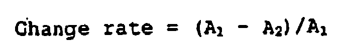
- At the same time, the error rate of the reproduced signals was measured.
- The results of measurement of the envelope change rate and the error rate are shown in Table 2.
[Table 2] Disk Error rate Change rate [%] (1) 2 × 10⁻⁵ 1 (2) 7 × 10⁻⁵ 6 (3) 6 × 10⁻⁵ 3 (4) 1 × 10⁻³ 4 (5) 8 × 10⁻⁴ 8 (6) 1 × 10⁻³ 10 - Whiledisks (1) through (3) gavesatisfactoryerrorrates, lower than the generally accepted
threshold 1 × 10⁻⁴ for error rates, the error rates of disks (4) through (6) were not low enough. - The envelop change rate was satisfactory, no more than 5% for disks (1) through (4), but greater than that for disks (5) and (6).
- When signals reproduced out of the
second information layer 3 of each disk were measured within a reproduced signal processing circuit consisting of a binarizing circuit and a PLL (phase lock loop) circuit, the disks (4) through (6) were unstable in the operation of the binarizing circuit because of their large envelope fluctuations and the disks (4) through (6) were not stable in the operation of the PLL circuit on account of their inadequate reproduced signal quality. - These results are considered attributable to the following reasons. In the disks (1) through (3), conceivably, as the transmittance of the recorded area and the transmittance of the unrecorded area in the
first information layer 2 vary little, the intensity of the laser beam reaching thesecond information layer 3 is varied little by the recording state of thefirst information layer 2, and the envelope varies little, resulting in stabilized binarizing operation and a reduced error rate. The results shown in Table 2 reveal the superiority of the disks (1), (2) and (3), and consequently Table 1 reveals that a satisfactory error rate or less than 1 × 10⁻⁴ ratio is obtained when the absolute value of the transmittance ratio is not more than 10%. - In the disks (4) through (6), as the average transmittance of the
first information layer 2 is low, the intensity of the laser beam reaching this information layer is less at the time of recording onto or reproducing out of thesecond information layer 3, conceivably resulting in deteriorated quality of reproduced signals and a higher error rate. The results shown in Table 2 reveal the inferiority of the disks (4), (5) and (6) and consequently Table 1 reveals that the error rate is not good enough, surpassing 1 × 10⁻⁴, when the average transmittance is less than 40%. - From these findings, it was known that, because the disks (1) through (3) were reduced in the absolute value of the transmittance ratio (Tc - Ta)/Tc to 10% or below and raised in the average transmittance (Ta + Tc)/2 of the
first information layer 2 to 40% or above, information could be satisfactorily recorded onto and reproduced out of thesecond information layer 3. - Furthermore, the film thickness conditions to enable the average transmittance (Ta + Tc) /2 to be raised to 40% or above and the absolute value of the transmittance ratio (Tc - Ta) /Tc to be reduced to 10% or below in the configuration shown in FIG. 2 were checked in detail by calculation. FIGS. 4 (a) and 4(b) are diagrams in which changes of the average transmittance (Ta + Tc) /2 and of the transmittance ratio (Tc - Ta) /Tc are plotted where, by way of example, the thickness ta of the recording layer is set to 10 nm, the thickness tb of the reflecting layer is set to 10 nm and the film thickness t1 of the first dielectric layer and the film thickness t2 of the second dielectric layer are varied. In FIGS. 4, the wavelength of the laser beam is set to 405 nm, and the film thicknesses of the upper dielectric and the lower dielectric are indicated in optical length with reference to the wavelength (λ) of the laser beam.
- If the film thickness of the dielectric layer which gives an average transmittance (Ta + Tc) /2 of 40% or more in FIG. 4 (a) and the film thickness of the dielectric layer which gives an absolute value of the transmittance ratio (Tc - Ta) /Tc of 10% or less in FIG. 4(b) canbe made compatible with each other, the combination of the film thicknesses of these recording layer and reflecting layer will enable the
first information layer 2 to be configured so as to make possible satisfactory recording and reproduction of information onto and out of thesecond information layer 3. - Table 3 shows, when the film thickness ta of the recording layer is varied from 2 to 32 nm and the film thickness tb of the reflecting layer, from 2 to 36 nm, whether or not a
first information layer 2 that has potential to keep the average transmittance (Ta + Tc) /2 at or above 40% and the absolute value of the transmittance ratio (Tc - Ta)/Tc at or below 10% can be configured. - In the table, ○ marks indicate that the pertinent film thicknesses ta and tb can keep the average transmittance at or above 40% and the absolute value of the transmittance ratio at or below 10%. To add, × marks indicate that, whatever ta and tb may be chosen, there is no possibility to keep the average transmittance at or above 40% and the absolute value of the transmittance ratio at or below 10%. In other words, there is no area whatsoever in which the average transmittance is from 40 to 50% and the transmittance ratio is from -10 to +10% in FIGS. 4(a) and 4(b).
- If similar calculations to those referenced in FIG. 4(a) and FIG. 4(b) are done on every combination of individual recording layers and reflecting layers and, with the film thickness of the dielectric layer varied, a point where the average transmittance and the transmittance ratio are compatible is found, it will be regarged that a
first information layer 2 satisfying the conditions can be configured.[Table 3] ta[nm] 2 4 6 8 10 12 14 16 18 20 22 24 26 28 30 32 2 O O O O O O × × × × × × × × × × 4 O O O O O O × × × × × × × × × × 6 O O O O O O × × × × × × × × × × 8 O O O O O O × × × × × × × × × × 10 O O O O O O × × × × × × × × × × tb[nm] 12 O O O O O O × × × × × × × × × × 14 O O O O O O × × × × × × × × × × 16 O O O O O O × × × × × × × × × × 18 O O O O O O × × × × × × × × × × 20 O O O O O × × × × × × × × × × × 22 O O O O O × × × × × × × × × × × 24 O O O O × × × × × × × × × × × × 26 O O O × × × × × × × × × × × × × 28 O O × × × × × × × × × × × × × × 30 O × × × × × × × × × × × × × × × 32 × × × × × × × × × × × × × × × × 34 × × × × × × × × × × × × × × × × 36 × × × × × × × × × × × × × × × × - This table reveals that a film thickness satisfying the following conditions provides a configuration that has potential to meet the requirements of 40% ormore in the average transmittance and 10% or less in the absolute value of the transmittance ratio.
- ta ≤ 12 when tb ≤ 18,
- ta ≤ 10 when 18 < tb ≤ 22, and
- ta ≤ 32 - tb when 22 < tb ≤ 30.
- Table 3 also shows that a configuration Meeting the above-stated requirements of the average transmittance and the transmittance ratio can be obtained with a configuration in which both the recording layer and the reflecting layer are thin. This means that the layers which have optical absorption in the
first information layer 2 are mainly the recording layer and the reflecting layer. It can further be the that, since the recording layer is nearer than the reflecting layer as viewed from the light source side, the absorption index of the recording layer is greater than the absorption index of the reflecting layer and that increasing the film thickness of the recording layer can influence the transmittance more than increasing the film thickness of the reflecting layer. - Further, when the values of the absorption index Aa of the recording layer in the amorphous state and the absorption index Ac of the recording layer in the crystalline state were calculated for the disks (1) and (3), the result was Aa> Ac. This is because, since the reflectivities of (1) and (3) were set to be Ra < Rc, in order to reduce the absolute value of the transmittance ratio (i.e. to substantially equalize Tc and Ta) configuration is made easier by giving a relationship of Aa > Ac to the absorption index of the recording layer (≤ 100% -reflectivity - transmittance). Conversely, where the reflectivities are caused to be Ra > Rc as in the case of the disk (2), a configuration satisfying the above-stated requirements can be readily obtained by giving the absorption index of the recording layer a relationship of Aa< Ac. Whereas relative magnitudes of Aa and Ac vary with the optical constants and the film thicknesses of the individual films constituting the information layers, if the optical constant of the recording film in the amorphous state is set to be na - ika and the optical constant in the crystalline state, nc - ikc, it is easier to obtain a configuration in which Tc and Ta are substantially equalized by having Aa > Ac as the absorption indices of the recording films and Ra < Rc as the reflectivities, where:

- Conversely, where:

- Incidentally, as the recording layer in the previous described embodiment has a relationship na+ka>nc+kc it is easier to obtain a configuration in which Tc and Ta are substantially equalized by having Aa > Ac as the absorption indices of the recording films and Ra < Rc as the reflectivities.
- To sum up the foregoing, whatever the optical constant may be, it is desirable for the relative magnitudes of Ta and To matching the relative magnitudes of Ra and Rc in the amorphous state to differ from the relative magnitudes of Ta and Tc matching the relative magnitudes of Ra and Rc in the crystalline state.
- As so far described, in the optical information recording medium in this embodiment, by reducing the absolute value of the transmittance ratio (Tc - Ta) /Tc to 100 or less and raising the average transmittance (Ta + Tc) /2 of the
first information layer 2 to 40% or more, sufficient intensity of the laser beam is enabled to reach thesecond information layer 3, and information can be accurately recorded and reproduced irrespective of whether or not information is recorded on thefirst information layer 2. - FIG. 5 is a sectional view showing an example of configuration of the
first information layer 2, which constitutes the nearer information layer in FIG. 1 as viewed from the incidence side of the laser beam. This mode differs from the first embodiment in that athird dielectric layer 13 is provided over the reflectinglayer 12. FIG. 6 is a diagram in which changes of the average transmittance (Ta + Tc) /2 and of the transmittance ratio (Tc - Ta)/Tc are plotted where the thickness of the recording layer is set to 10 nm, the thickness of the reflecting layer is set to 10 nm, the thickness of the third dielectric layer is set to 10 nm and the film thicknesses of the first dielectric layer and the second dielectric layer are varied. To compare FIG. 6 with FIG. 4, in spite of the same thicknesses of the recording layer and of the reflecting layer, the provision of the third dielectric layer has expanded the area in which the absolute value of the transmittance ratio (Tc - Ta)/Tc is 10% or less. Further, if the thickness of the third dielectric layer is selected properly, it will also be possible to enhance the average transmittance. Thus, this has the role of increasing the freedom of configuration of thefirst information layer 2. - Table 4 shows an example of film thickness configuration of the
first information layer 2 of a disk produced on a trial basis in this embodiment, its calculated transmittances in the amorphous state (Ta) and in the crystalline state (Tc), reflectivities in the amorphous state (Ra) and the crystalline state (Ra), absorption indices in the amorphous state (Aa) and in the crystalline state (Ac), transmittance ratio between the amorphous state and the crystalline state (Tc - Ta)/Tc, and average transmittance (Ta + Tc)/2.[Table 4] Disk ta [nm] tb [nm] t1 [nm] t2 [nm] ta [nm] Rc [%] Ra [%] Tc [%] Ta [%] Ac [%] Aa [%] Transmittance ratio [%] Average transmittance [%] (7) 8 10 40 22 30 7 0 41 40 47 66 2 41 (8) 6 8 68 12 10 15 44 46 35 44 -4 45 (9) 5 10 62 28 50 12 2 41 42 42 53 -3 42 (10) 6 26 50 59 50 21 28 45 38 - - 15 41 (11) 10 30 34 68 70 27 35 33 36 - - -10 34 (12) 8 28 68 50 70 13 31 29 21 - - 28 25 - In this embodiment, as shown in Table 4, disks differing in transmittance ratio and average transmittance of the
first information layer 2 were prepared by varying the thickness ta of the recording layer, the thickness tb of the reflecting layer, the thickness t1 of the first dielectric layer, the thickness t2 of the second dielectric layer, and the thickness t3 of the third dielectric layer. - The disks were prepared in a similar way to those in the first embodiment, differing from the first embodiment in the following respects. As the
first information layer 2, there were formed in succession a third dielectric layer of ZnS-SiO2 to t3 nm, a reflecting layer of AgPdCu to tb nm, a second dielectric layer of ZnS-SiO2 to t2 nm, a recording layer of GeSbTe to ta nm, and a first dielectric layer of ZnS-SiO2 to t2 nm. - Then, a recording/reproducing test was carried out using the six different disks shown in Table 3. As in the first embodiment, each disk was turned at a linear speed of 5 m/s, either one of the information layers 2 and 3 of the disk was irradiated with a semiconductor laser beam of 405 nm in wavelength, narrowed down with an objective lens of 0.85 in numerical aperture (NA).
- The results of measurement of the envelope change rate and the error rate are shown in Table 5.
[Table 5] Disk Error rate Change rate[%] (7) 6 × 10⁻⁵ 1 (8) 3 × 10⁻⁵ 2 (9) 6 × 10⁻⁵ 2 (10) 1 × 10⁻³ 8 (11) 5 × 10⁻⁴ 5 (12) 4 × 10⁻³ 14 - While disks (7) through (9) gave satisfactory error rates, lower than the generally accepted
threshold 1 × 10⁻⁴ for error rates, the error rates of disks (10) through (12) were not low enough. The envelop change rate was satisfactory, no more than 5% for disks (7) through (9) and (11), but greater than that for disks (10) and (12). - When signals reproduced out of the
second information layer 3 of each disk were measured within a reproduced signal processing circuit consisting of a binarizing circuit and a PLL (phase lock loop) circuit, the disks (11) and (12) were unstable in the operation of the binarizing circuit because of their large envelope fluctuations, manifesting high error rates. The disks (10) through (12) were not stable in the operation of the PLL on account of their inadequate reproduced signal quality, which contributed to raising error rates. - The results shown in Table 4 and Table 5 reveal that low enough error rates are obtained, less than 1 × 10⁻⁴, when the absolute value of the transmittance ratio is not more than 10% and the average transmittance is not less than 40%.
- From these findings, it was known that, because the disks (7) through (9) were raised in the average transmittance (Ta + Tc) /2 of the
first information layer 2 to 40% or above and reduced in the absolute value of the transmittance ratio (Tc - Ta) /Tc to 10% or below, information could be satisfactorily recorded onto and reproduced out of thesecond information layer 3. - Furthermore, the film thickness conditions to enable the average transmittance (Ta + Tc)/2 to be raised to 40% or above and the absolute value of the transmittance ratio (Tc - Ta) /Tc to be reduced to 10% or below in the configuration shown in FIG. 5 were checked in detail by calculation.
- Table 6 shows, when the film thickness ta of the recording layer is varied from 2 to 32 nm and the film thickness tb of the reflecting layer, from 2 to 36 nm, whether or not a
first information layer 2 that has potential to keep the average transmittance (Ta + Tc) /2 at or above 40% and the absolute value of the transmittance ratio (Tc - Ta) /Tc at or below 10% can be configured. Further, Table 7 shows a case in which the film thicknesses of the recording layer and of the reflecting layer were similarly varied and the film thickness t3 of the third dielectric layer was set to 30 nm; Table 8, a similar case in which the thickness was 50 nm, and Table 9, another case in which the thickness was 70 nm.[Table 6] t3=10[nm] ta[nm] 2 4 6 8 10 12 14 16 18 20 22 24 26 28 30 32 2 O O O O O O × × × × × × × × × × 4 O O O O O O × × × × × × × × × × 6 O O O O O O × × × × × × × × × × 8 O O O O O O × × × × × × × × × × 10 O O O O O O × × × × × × × × × × tb[nm] 12 O O O O O O × × × × × × × × × × 14 O O O O O O × × × × × × × × × × 16 O O O O O O × × × × × × × × × × 18 O O O O O O × × × × × × × × × × 20 O O O O O × × × × × × × × × × × 22 O O O O O × × × × × × × × × × × 24 O O O O O × × × × × × × × × × × 26 O O O O × × × × × × × × × × × × 28 O O O O × × × × × × × × × × × × 30 O O O × × × × × × × × × × × × × 32 O × × × × × × × × × × × × × × × 34 × × × × × × × × × × × × × × × × 36 × × × × × × × × × × × × × × × × [Table 7] t3=30[nm] ta[nm] 2 4 6 8 10 12 14 16 18 20 22 24 26 28 30 32 2 O O O O O O × × × × × × × × × × 4 O O O O O O × × × × × × × × × × 6 O O O O O O × × × × × × × × × × 8 O O O O O O × × × × × × × × × × 10 O O O O O O × × × × × × × × × × tb[nm] 12 O O O O O O × × × × × × × × × × 14 O O O O O O × × × × × × × × × × 16 O O O O O O × × × × × × × × × × 18 O O O O O O × × × × × × × × × × 20 O O O O O O × × × × × × × × × × 22 O O O O O O × × × × × × × × × × 24 O O O O O O × × × × × × × × × × 26 O O O O O × × × × × × × × × × × 28 O O O O O × × × × × × × × × × × 30 O O O O × × × × × × × × × × × × 32 O O O × × × × × × × × × × × × × 34 O × × × × × × × × × × × × × × × 36 × × × × × × × × × × × × × × × × [Table 8] t3=50[nm] ta[nm] 2 4 6 8 10 12 14 16 18 20 22 24 26 28 30 32 2 O O O O O O O × × × × × × × × × 4 O O O O O O O × × × × × × × × × 6 O O O O O O O × × × × × × × × × 8 O O O O O O O × × × × × × × × × 10 O O O O O O O × × × × × × × × × tb[nm] 12 O O O O O O O × × × × × × × × × 14 O O O O O O O × × × × × × × × × 16 O O O O O O × × × × × × × × × × 18 O O O O O O × × × × × × × × × × 20 O O O O O O × × × × × × × × × × 22 O O O O O × × × × × × × × × × × 24 O O O O × × × × × × × × × × × × 26 O O O × × × × × × × × × × × × × 28 O O × × × × × × × × × × × × × × 30 × × × × × × × × × × × × × × × × 32 × × × × × × × × × × × × × × × × 34 × × × × × × × × × × × × × × × × 36 × × × × × × × × × × × × × × × × [Table 9] t3=70[nm] ta[nm] 2 4 6 8 10 12 14 16 18 20 22 24 26 28 30 32 2 O O O O O O O × × × × × × × × × 4 O O O O O O O × × × × × × × × × 6 O O O O O O O × × × × × × × × × 8 O O O O O O O × × × × × × × × × 10 O O O O O O O × × × × × × × × × tb[nm] 12 O O O O O O × × × × × × × × × × 14 O O O O O O × × × × × × × × × × 16 O O O O O O × × × × × × × × × × 18 O O O O O O × × × × × × × × × × 20 O O O O O × × × × × × × × × × × 22 O O O O × × × × × × × × × × × × 24 O O O × × × × × × × × × × × × × 26 O × × × × × × × × × × × × × × × 28 × × × × × × × × × × × × × × × × 30 × × × × × × × × × × × × × × × × 32 × × × × × × × × × × × × × × × × 34 × × × × × × × × × × × × × × × × 36 × × × × × × × × × × × × × × × × - These tables reveal that a film thickness satisfying the following conditions provides a configuration that meets the aforementioned requirements about the average transmittance and the transmittance ratio if the recording layer is made ta[nm] thick and the metallic reflecting layer tb[nm] thick irrespective of whatever the film thickness of the third dielectric layer is between 10 and 70 nm:
- tb ≤ 12 when tb ≤ 18,
- ta ≤ 38 - ta when 16 < ta ≤ 18
- ta ≤ 10 when 18 < ta ≤ 20
- ta ≤ 30 - ta when 20 < ta ≤ 24 and
- ta ≤ 28 - ta when 24 < ta ≤ 26.
- As is seen from Table 6 through Table 9, a configuration meeting the above-stated requirements of the average transmittance and the transmittance ratio can be obtained with a configuration in which both the recording layer and the reflecting layer are thin. This means that the layers which have optical absorption in the
first information layer 2 are mainly the recording layer and the reflecting layer. - Further, when the values of the absorption index Aa of the recording layer in the amorphous state and the absorption index Ac of the recording layer in the crystalline state were calculated for the disks (7) through (9), the result was Aa > Ac. This is because, since the reflectivities of (7) through (9) were set to be Ra < Rc, in order to reduce the absolute value of the transmittance ratio (i.e. to substantially equalize Tc and Ta) configuration is made easier by giving a relationship of Aa > Ac to the absorption index of the recording layer (≤ 1000% - reflectivity - transmittance).
- As hitherto described, the optical information recording medium in this embodiment as well, if so configured as to reduce the absolute value of the transmittance ratio (Tc - Ta)/Tc to 10% or below and raise the average transmittance (Ta + Tc)/2 of the
first information layer 2 to 40% or above, sufficient intensity of the laser beam will be enabled to reach thesecond information layer 3, and information can be accurately recorded and reproduced irrespective of whether or not information is recorded on thefirst information layer 2. - Finally, whereas the aforementioned transmittances Ta and Tc are usually measured with an optical instrument, such as a spectroscope, it is made easier to measure the difference between Tc and Ta by utilizing reproduced signals obtained when the second information layer is irradiated with an information reproducing laser beam as shown in FIG. 7. Such an optical measuring method will be described anew with reference to a drawing.
- FIGS. 9 are schematic diagrams illustrating such a first optical measuring method, in which the upper part comprises schematic sections showing how the the upper part comprises schematic sections showing how the laser beam irradiates each information layer and the lower part, a waveform diagram of a reproduced signal obtained from the laser beam reflected by the second information layer.
- first, in a state in which nothing is recorded on the first information layer as shown in the upper part of FIG. 9(a), irradiation with a laser beam is carried out with focus on the second information layer. It is desirable for the irradiating position in this process to be set in a so-called still state, in which a return to the original position takes place, for instance, at every full turn, because in this way comparison with the result of measurement at the next step is facilitated. The reflected intensity is converted into an electric current or a voltage by a photodetector for signal reproduction or the like, and observed as a reproduced waveform of a substantially direct current as shown in the lower part of FIG. 9(a). Although the actual waveform is more or less uneven because its is fluctuated by the reflectivity of the optical disk or the like, it can be considered a D. C. waveform when averaged over time. The zero level of the longitudinal axis of this diagram represents the output of the photodetector when the optical disk is removed from the optical path of the laser beam. Therefore, level Sa shown in the diagram represents the reflected intensity in a state in which nothing is recorded on the first information layer.
- Next, random signals or monotone signals are recorded in a position on the first information layer immediately below the position in which Sa was measured at
step 1 as shown in the upper part of FIG. 9(b). The recording range is designated to include the whole area which, when a laser beam is focused on the second information layer, the laser beam passes the first information layer. If the wavelength of the laser beam is 405 nm, the NA of the objective lens is 0.85, the thickness of the middle layer is 30 µm, and the refractive index of the middle layer is 1.60, the diameter of the laser beam in the first information layer will be approximately 37.6 µm. With this diameter and the eccentricity between the first and second layers taken into consideration, the required recording range may be 200 µm or so. - Finally, irradiation with the laser beam is carried out with focus on the second information layer through the first information layer on which random signals or monotone signals are recorded as shown in the upper part of FIG. 9(c). It is desirable with a view to greater accuracy of measurement for the irradiating position then to coincide with the track measured at
step 1. The reflected intensity is observed as a reproduced waveform of a substantially direct current as shown in the lower part of FIG. 9(c). Level Sb shown in the diagram represents the reflected intensity in a recorded of the first information layer. This diagram shows a case in which the transmittance is lower in the recorded state than in the unrecorded state. - From Sa and Sb, the difference in transmittance between the unrecorded state and the recorded state of the first information layer can be figured out by the following calculation. Thus, where a is the ratio of the area of recording marks to the whole sectional area of the laser beam in the section of the laser beam on the first information layer when the laser beam is focused on the second information layer, the equivalent transmittance Ta' of the recorded first information layer is:


- By these
steps 1 through 4, changes in transmittance between the unrecorded state and the recorded state of the first information layer can be easily measured without having to use a special measuring instrument. - FIGS. 10 are schematic diagrams showing the procedure of a second optical measuring method, in which the upper part comprises schematic sections showing how the laser beam irradiates each information layer and the lower part, a waveform diagram of a reproduced signal obtained from the laser beam reflected by the second information layer.
- First, in a state in which nothing is recorded on the first information layer as shown in the upper part of FIG. 10(a), irradiation with a laser beam is carried out with focus on the second information layer, random or monotone signals are recorded on a predetermined track of the second information layer. Then the signals recorded on that track are irradiated with a laser beam of the reproduction level, converted into an electric current or a voltage by a photodetector or the like, and observed as an envelope waveform having a fixed amplitude as shown in the lower part of FIG. 10(a). The amplitude A1 shown in the diagram represents the reproduced signal amplitude in a state in which nothing is recorded on the first information layer.
- Next, the random signals or monotone signals are recorded in a position on the first information layer immediately below the position in which A1 was measured at
step 1 as shown in the upper part of FIG. 10(b). The recording range is the same as according the first optical measuring method. - Finally, irradiation with the laser beam is carried out with focus on the second information layer through the first information layer on which random signals or monotone signals are recorded as shown in the upper part of FIG. 10(c). The irradiating position then is caused to coincide with the track measured at
step 1. The reproduced signals are observed as an envelope waveform having a fixed amplitude as shown in the lower part of FIG. 10(c). The amplitude A2 shown in the diagram represents the reproduced signal amplitude in the recorded state of the first information layer. This diagram, too, shows a case in which the transmittance is lower in the recorded state than in the unrecorded state of the first information layer. - By replacing Sa with A1 and Sb with A2 in the calculation shown according to the first optical measuring method, the transmittance ratio (Tc - Ta) /Tc between the unrecorded state and the recorded state of the first information layer can be figured out.
- By these
steps 1 through 4, changes in transmittance between the unrecorded state and the recorded state of the first information layer can be easily measured without having to use a special measuring instrument. Also, since the method described with reference to FIGS. 10 uses reproduced amplitudes A1 and A2 for comparing the levels of reflected intensity, even if part of the reflected beam from the first information layer goes astray and comes incident on the photodetector, the difference in transmittance can be measured with greater accuracy because the stray light would be cancelled when the amplitudes are measured. On the other hand, by the method described with reference to FIG. 9 as well, if the size of the photodetector is made sufficiently small and the stray intensity is suppressed to, for instance, about 2% of the total incident intensity, the tolerance of the transmittance difference that is measured can be suppressed to 2/100, making possible, sufficiently accurate measurement. - Meanwhile as for the second optical measuring method as described in FIG. 11,a transmittance ratio (|Tc-Ta|/Tc) between the recorded state and unrecorded state of the first information layer can be obtained in such manner that the differences A1, and A2. between the zero level and upper envelope of the modulation amplitude are detected and the S, is replaced with A1, and Sb is replaced with A2, in the calculation described in the first optical measuring method description.
- By using the optical measuring methods described so far, the transmittance ratio can be easily figured out through Equation (1). Since the desirable transmittance ratio of the first information layer is 10% or less, if Equation (1) is used, it will be satisfactory for Sa and Sb that are obtained by the first optical measuring method to meet the requirement of:


- To add, although the
first information layer 2 is configured of four layers as shown in FIG. 2 or five layers as shown in FIG. 5 in the media of the above-described modes of implementation, a multi-layered configuration having an interface layer between each adjacent pair of these layers can also be used if it is so structure as to satisfy the above-stated conditions regarding the transmittance ratio and/or the average transmittance. Some other configurations than those illustrated in FIG. 2 and FIG. 5, such as having no reflecting layer, can be used as well. Nor are the materials of the individual layers limited to those used in these modes of implementation. - While each optical disk in the above-described modes of implementation has two information layers, it is also acceptable for each disk to have three or more information layers as shown in FIG. 8, and to have a nearer positioned information layer than the farthest information layer as viewed from the incidence side of the laser beam satisfy the above-stated requirement regarding the transmittance ratio.
- This synthesized transmittance is the product of the transmittances of the information layers. There exist, depending on the combination of the recorded and unrecorded states of different layers, a state in which the synthesized transmittance is at its minimum (this transmittance is represented by Tmin) and a state in which it is at its maximum (this transmittance is represented by Tmax). Similar to the case in which there are two information layers, in order to reduce the variations of the intensity of the laser beam reaching any information layer farther than this plurality of information layers, the configuration can be:

- In this case, since all the nearer positioned information layers may not necessarily secure an average transmittance of 40% or more, the S/N ratio of the reproduction circuit should be enhanced in order to ensure adequate signal quality.
- Further in the optical measuring methods described above, The medium to be detected can has three or more information layers. In such case maximum change of the transmittance for the nearer plurality of the information layers can be detected by detecting the respective reflection amounts of case (a) and case (b). Here the case (a) means that the'synthesized transmittance of the plurality of information layers positioned nearer than the farthest information layer from the incidence side of said laser beam, is minimum. The case (b) means that the synthesized transmittance of the plurality of information layers positioned nearer than the farthest information layer from the incidence side of said laser beam, is maximum.
- And in the optical measuring method described above, the transmittance ratio is calculated in the
step 4 on the basis of the measured Sa (or A1,A1') and Sb (or A2,A2'). But instead of it, by detecting the changing of such measured values the goodness of the change of the transmittance of the nearer positioned information layer can be easily obtained without measuring the transmission foctor ratio. - For example as parameters representing the changing of the signals, (Sa-Sb) /Sc or (A1-A2)/ A1 or (A1'-A2')/A1, is defined. By obtaining such parameters, the amount of the effect which is caused by the nearer information layer against the quality of the reproduced signal of the farthest information layer, can be estimated without getting the transmittance ratio (Tc - Ta) /Tc. Then the goodness of the transmittance changing of the nearer information layer can be easily judged.
- Meanwhile in the practical measuring condition, the Sa (or A1,A1') and Sb (or A2,A2') vary because of the unevenness of the reflectivities etc. of the disk, however the changing of the transmittance of the nearer information layer effect largely against the varying of the parameters.
- Therefore even if the above parameters are obtained by recording locally signals on the nearer information layer, measuring the changing of the amount of the reflected beam from the farthest information layer via the nearer information layer and detecting maximum value as Sa and minimum value as Sb, there is no problem for judging the goodness of the changing of the transmittance of the nearer information layer. As for the modulation amplitude A1, A1', A2, A2' there is noproblem as like.
- Furthermore, the modulation system and recording density usable in the above-described modes of implementation are not limited to those described above, but it goes without saying that can be in any appropriate forms for the medium itself or the recording/reproducing apparatus.
- As described so far, the optical information recording medium can cause sufficient intensity of the laser beam to reach the information layer farther inside, and can accurately record and reproduce onto and out of the farther information layer irrespective of whether or not any information is recorded on the nearer information layer.
- And, the optical measuring method of the present invention can easily detect the changing of the transmittance of the nearer information layer in such conditions of recorded or unrecorded.
Claims (7)
- An optical measuring method for determining a change in transmittance in a first information layer (2) of an optical information recording medium having two information layers (2, 3), said first information layer (2) having a recording layer varying between an unrecorded state and a recorded state,
said first information layer (2) is positioned nearer than the second information layer (3) from the incidence side of said laser beam (8), and
said laser beam (8) is first transmitted through said first information layer (2), then reflected by said second information layer (3), and again transmitted through said first information layer (2), so that to come out of said optical information recording medium and to be received by a photodetector,
characterized by
a step of measuring with said photodetector the modulation amplitude of said laser beam (8) when the area transmitting said laser beam in the recording layer contained in said first information layer (2) is in an unrecorded state, wherein the laser beam is modulated by information signals recorded on said second information layer (3),
a step of measuring with said photodetector the modulation amplitude of said laser beam (8) when a part of or the whole of the area transmitting said laser beam in the recording layer contained in said first information layer (2) is in a recorded state, wherein the laser beam is modulated by said information signals recorded on said second information layer (3),
during the step of measuring when said first information layer is either in an unrecorded state or a recorded state said laser beam is focussed on said second information layer, and
a step of determining a change in the transmittance of said first information layer (2) according to
wherein
Ta and Tc represent the transmittance of said first information layer (2) when said recording layer is in a recorded state and in an unrecorded state, respectively,
A1 and A2 represent the modulation amplitude of said laser beam (8) when the area transmitting said laser beam in the recording layer of said first information layer (2) is in an unrecorded state and in a recorded state, respectively, and
α represents the ratio of the area of recording marks to the whole sectional area of the laser beam (8) in the section of the laser beam on the first information layer (2) when the laser beam is focused on the second information layer (3). - An optical measuring method for determining a change in transmittance in a plurality of information layers (2) of an optical information recording medium having three or more information layers (2, 3), said plurality of information layers (2) having recording layers each varying between an unrecorded state and a recorded state, and a synthesized transmittance of said plurality of information layers (2) is determined by a combination of unrecorded and recorded states of respective recording layers,
said plurality of information layers (2) is positioned nearer than a predetermined information layer (3) from the incidence side of said laser beam (8),
said laser beam (8) is first transmitted through said plurality of information layers (2), then reflected by said predetermined information layer (3), again transmitted through said plurality of information layers (2), so that to come out of said optical information recording medium and to be received by a photodetector,
characterized by
a step of measuring with said photodetector a modulation amplitude of said laser beam (8) when the synthesized transmittance of said plurality of information layers (2) is minimum, wherein the laser beam is modulated by said information signals recorded on said predetermined information layer (3) located farther inside than said plurality of information layers,
a step of measuring with said photodetector a modulation amplitude of said laser beam (8) when the synthesized transmittance of said plurality of information layers (2) is maximum, wherein the laser beam is modulated by said information signals recorded on said predetermined information layer (3),
during the step of measuring when the synthesized transmittance of said plurality of information layers (2) is either minimum or maximum said laser beam is focussed on said predetermined information layer, and
a step of determining a change in the transmittance of said plurality of information layers (2) according to
wherein
Tmin and Tmax represent the minimum synthesized transmittance and the maximum synthesized transmittance of said plurality of information layers (2), respectively, and
A1 and A2 represent the modulation amplitude of said laser beam (8) when the synthesized transmittance of said plurality of information layers (2) is minimum and maximum, respectively. - The optical measuring method according to any of claims 1 to 2, wherein one of said unrecorded state and said recorded state is a crystalline state and the other of said unrecorded state and said recorded state is an amorphous state.
- The optical measuring method according to any of claims 1 and 3, whereby information signals are recorded on said second information layer (3) before said first information layer (2) is changed into a recorded state.
- The optical measuring method according to any of claims 1, 3 and 4, wherein random information signals are recorded on said first and second information layer.
- The optical measuring method according to claim 2, whereby information signals are recorded on said father information layer (3) before recording information signals on said plurality of information layers (2).
- The optical measuring method according to claim 6, wherein random information signals are recorded on said farther information layer (3) and said plurality of information layers (2).
Applications Claiming Priority (5)
| Application Number | Priority Date | Filing Date | Title |
|---|---|---|---|
| JP2001314827 | 2001-10-12 | ||
| JP2001314827 | 2001-10-12 | ||
| JP2002067695 | 2002-03-12 | ||
| JP2002067695 | 2002-03-12 | ||
| EP02022923A EP1302934B1 (en) | 2001-10-12 | 2002-10-10 | Optical information recording medium, its measuring method and optical information recording/reproducing method |
Related Parent Applications (1)
| Application Number | Title | Priority Date | Filing Date |
|---|---|---|---|
| EP02022923A Division EP1302934B1 (en) | 2001-10-12 | 2002-10-10 | Optical information recording medium, its measuring method and optical information recording/reproducing method |
Publications (2)
| Publication Number | Publication Date |
|---|---|
| EP1513139A1 EP1513139A1 (en) | 2005-03-09 |
| EP1513139B1 true EP1513139B1 (en) | 2007-09-05 |
Family
ID=26623863
Family Applications (2)
| Application Number | Title | Priority Date | Filing Date |
|---|---|---|---|
| EP04028164A Expired - Lifetime EP1513139B1 (en) | 2001-10-12 | 2002-10-10 | Method to determine a change in the transmittance of an optical information recording medium |
| EP02022923A Expired - Lifetime EP1302934B1 (en) | 2001-10-12 | 2002-10-10 | Optical information recording medium, its measuring method and optical information recording/reproducing method |
Family Applications After (1)
| Application Number | Title | Priority Date | Filing Date |
|---|---|---|---|
| EP02022923A Expired - Lifetime EP1302934B1 (en) | 2001-10-12 | 2002-10-10 | Optical information recording medium, its measuring method and optical information recording/reproducing method |
Country Status (4)
| Country | Link |
|---|---|
| US (1) | US6893698B2 (en) |
| EP (2) | EP1513139B1 (en) |
| KR (1) | KR100939850B1 (en) |
| DE (2) | DE60222072T2 (en) |
Families Citing this family (7)
| Publication number | Priority date | Publication date | Assignee | Title |
|---|---|---|---|---|
| AU2003266522A1 (en) * | 2002-09-18 | 2004-04-08 | Matsushita Electric Industrial Co., Ltd. | Optical information recording medium and production method therefor |
| CN1591626A (en) * | 2003-09-02 | 2005-03-09 | 皇家飞利浦电子股份有限公司 | Multi-layer CD and its mfg. method |
| JP2005302261A (en) * | 2004-03-19 | 2005-10-27 | Ricoh Co Ltd | Optical recording medium |
| WO2006013978A1 (en) * | 2004-08-05 | 2006-02-09 | Matsushita Electric Industrial Co., Ltd. | Optical recording medium, optical recording medium information recording/reproducing method and information recording/reproducing device |
| TWI267846B (en) * | 2004-11-25 | 2006-12-01 | Ritek Corp | Dual-layer recordable optical disc and manufacturing method thereof |
| JP4107290B2 (en) * | 2004-12-24 | 2008-06-25 | ティアック株式会社 | Optical disk device |
| EP1714757B1 (en) * | 2005-04-21 | 2008-09-10 | Rohm and Haas Company | Wood preservatives |
Family Cites Families (12)
| Publication number | Priority date | Publication date | Assignee | Title |
|---|---|---|---|---|
| US2002A (en) * | 1841-03-12 | Tor and planter for plowing | ||
| JPH11195243A (en) * | 1997-12-26 | 1999-07-21 | Sony Corp | Multilayer optical disc and recording / reproducing device |
| TW473712B (en) * | 1998-05-12 | 2002-01-21 | Koninkl Philips Electronics Nv | Rewritable double layer optical information medium |
| EP0957477A3 (en) * | 1998-05-15 | 2003-11-05 | Matsushita Electric Industrial Co., Ltd. | Optical information recording medium, recording and reproducing method therefor and optical information recording and reproduction apparatus |
| JP2000235732A (en) * | 1999-02-12 | 2000-08-29 | Sony Corp | Multilayer optical disc |
| JP4085503B2 (en) * | 1999-02-12 | 2008-05-14 | ソニー株式会社 | Multi-layer optical disc |
| US7065035B1 (en) * | 1999-10-25 | 2006-06-20 | Matsushita Electric Industrial Co., Ltd. | Optical multilayer disk, multiwavelength light source, and optical system using them |
| JP4423518B2 (en) | 2000-01-25 | 2010-03-03 | ノーリツ鋼機株式会社 | Network pre-judge system |
| TW575873B (en) * | 2000-07-13 | 2004-02-11 | Matsushita Electric Industrial Co Ltd | Information recording medium, method for producing the same, and recording/reproducing method using the same |
| TWI233098B (en) * | 2000-08-31 | 2005-05-21 | Matsushita Electric Industrial Co Ltd | Data recoding medium, the manufacturing method thereof, and the record reproducing method thereof |
| JP2002230828A (en) * | 2001-01-31 | 2002-08-16 | Pioneer Electronic Corp | Information recording medium |
| EP1426939B1 (en) * | 2001-09-12 | 2008-10-15 | Matsushita Electric Industrial Co., Ltd. | Optical information recording medium |
-
2002
- 2002-10-10 EP EP04028164A patent/EP1513139B1/en not_active Expired - Lifetime
- 2002-10-10 EP EP02022923A patent/EP1302934B1/en not_active Expired - Lifetime
- 2002-10-10 DE DE60222072T patent/DE60222072T2/en not_active Expired - Lifetime
- 2002-10-10 DE DE60222306T patent/DE60222306T2/en not_active Expired - Lifetime
- 2002-10-12 KR KR1020020062228A patent/KR100939850B1/en not_active Expired - Fee Related
- 2002-10-15 US US10/270,820 patent/US6893698B2/en not_active Expired - Lifetime
Non-Patent Citations (1)
| Title |
|---|
| None * |
Also Published As
| Publication number | Publication date |
|---|---|
| EP1302934A3 (en) | 2003-08-13 |
| KR100939850B1 (en) | 2010-01-29 |
| DE60222072D1 (en) | 2007-10-11 |
| EP1302934A2 (en) | 2003-04-16 |
| DE60222306T2 (en) | 2008-01-03 |
| DE60222072T2 (en) | 2008-01-03 |
| KR20030030982A (en) | 2003-04-18 |
| US6893698B2 (en) | 2005-05-17 |
| US20030134077A1 (en) | 2003-07-17 |
| HK1051594A1 (en) | 2003-08-08 |
| EP1302934B1 (en) | 2007-08-29 |
| EP1513139A1 (en) | 2005-03-09 |
| DE60222306D1 (en) | 2007-10-18 |
Similar Documents
| Publication | Publication Date | Title |
|---|---|---|
| EP1300836B1 (en) | Optical information recording method, optical information recording and reproducing device, and optical information recording medium | |
| US6580678B2 (en) | Rewritable compact disk and manufacturing method thereof | |
| JP4150155B2 (en) | Information recording medium, information recording method, reproducing method, recording / recording apparatus, and information reproducing apparatus | |
| US20040157158A1 (en) | Optical recording medium | |
| EP0578015B1 (en) | Optical information recording medium | |
| US20010005350A1 (en) | Optical information recording medium, method for producing the same, and method and apparatus for recording / reproducing information thereon | |
| US6956810B2 (en) | Phase change optical information recording medium | |
| US7345976B2 (en) | Method for recording data in optical recording medium, apparatus for recording data in optical recording medium and optical recording medium | |
| US20040027966A1 (en) | Optical recording/reproducing method and optical recording medium | |
| EP1513139B1 (en) | Method to determine a change in the transmittance of an optical information recording medium | |
| US20080037406A1 (en) | Optical Recording Medium | |
| US7684300B2 (en) | Optical information recording and reproducing apparatus | |
| EP1475787A1 (en) | Method for reproducing information from optical recording medium, information reproducer, and optical record medium | |
| US7566523B2 (en) | Optical information-recording media and optical information-recording/reproduction apparatus | |
| HK1070979A1 (en) | Method to determine a change in the transmittance of an optical information recording medium | |
| HK1070979B (en) | Method to determine a change in the transmittance of an optical information recording medium | |
| HK1051594B (en) | Optical information recording medium, its measuring method and optical information recording/reproducing method | |
| JPH064900A (en) | Optical information recording medium and structure design method thereof | |
| JP4231060B2 (en) | Layer determination method, information recording method, and information reproducing method | |
| JP4084160B2 (en) | Optical measuring method and optical measuring device | |
| CN100514452C (en) | Optical information recording medium and optical information recording/reproducing method | |
| JP2005339801A (en) | Optical information recording medium | |
| HK1076531A1 (en) | Information recording method and information recording medium | |
| KR19990069853A (en) | Phase change optical disk | |
| HK1076531B (en) | Information recording method and information recording medium |
Legal Events
| Date | Code | Title | Description |
|---|---|---|---|
| PUAI | Public reference made under article 153(3) epc to a published international application that has entered the european phase |
Free format text: ORIGINAL CODE: 0009012 |
|
| 17P | Request for examination filed |
Effective date: 20041126 |
|
| AC | Divisional application: reference to earlier application |
Ref document number: 1302934 Country of ref document: EP Kind code of ref document: P |
|
| AK | Designated contracting states |
Kind code of ref document: A1 Designated state(s): DE FR GB |
|
| RIN1 | Information on inventor provided before grant (corrected) |
Inventor name: TAKASHI, NISHIHARA Inventor name: KENICHI, NISHIUCHI Inventor name: NAOYASU, MIYAGAWA Inventor name: RIE, KOJIMA Inventor name: NOBORU, YAMADA Inventor name: KENJI, NARUMI |
|
| REG | Reference to a national code |
Ref country code: HK Ref legal event code: DE Ref document number: 1070979 Country of ref document: HK |
|
| 17Q | First examination report despatched |
Effective date: 20050531 |
|
| AKX | Designation fees paid |
Designated state(s): DE FR GB |
|
| GRAP | Despatch of communication of intention to grant a patent |
Free format text: ORIGINAL CODE: EPIDOSNIGR1 |
|
| GRAS | Grant fee paid |
Free format text: ORIGINAL CODE: EPIDOSNIGR3 |
|
| GRAA | (expected) grant |
Free format text: ORIGINAL CODE: 0009210 |
|
| AC | Divisional application: reference to earlier application |
Ref document number: 1302934 Country of ref document: EP Kind code of ref document: P |
|
| AK | Designated contracting states |
Kind code of ref document: B1 Designated state(s): DE FR GB |
|
| REG | Reference to a national code |
Ref country code: GB Ref legal event code: FG4D |
|
| REF | Corresponds to: |
Ref document number: 60222306 Country of ref document: DE Date of ref document: 20071018 Kind code of ref document: P |
|
| REG | Reference to a national code |
Ref country code: HK Ref legal event code: GR Ref document number: 1070979 Country of ref document: HK |
|
| ET | Fr: translation filed | ||
| PLBE | No opposition filed within time limit |
Free format text: ORIGINAL CODE: 0009261 |
|
| STAA | Information on the status of an ep patent application or granted ep patent |
Free format text: STATUS: NO OPPOSITION FILED WITHIN TIME LIMIT |
|
| 26N | No opposition filed |
Effective date: 20080606 |
|
| REG | Reference to a national code |
Ref country code: FR Ref legal event code: PLFP Year of fee payment: 15 |
|
| REG | Reference to a national code |
Ref country code: FR Ref legal event code: PLFP Year of fee payment: 16 |
|
| PGFP | Annual fee paid to national office [announced via postgrant information from national office to epo] |
Ref country code: FR Payment date: 20170918 Year of fee payment: 16 |
|
| PGFP | Annual fee paid to national office [announced via postgrant information from national office to epo] |
Ref country code: DE Payment date: 20171004 Year of fee payment: 16 |
|
| PGFP | Annual fee paid to national office [announced via postgrant information from national office to epo] |
Ref country code: GB Payment date: 20171004 Year of fee payment: 16 |
|
| REG | Reference to a national code |
Ref country code: DE Ref legal event code: R119 Ref document number: 60222306 Country of ref document: DE |
|
| GBPC | Gb: european patent ceased through non-payment of renewal fee |
Effective date: 20181010 |
|
| PG25 | Lapsed in a contracting state [announced via postgrant information from national office to epo] |
Ref country code: DE Free format text: LAPSE BECAUSE OF NON-PAYMENT OF DUE FEES Effective date: 20190501 |
|
| PG25 | Lapsed in a contracting state [announced via postgrant information from national office to epo] |
Ref country code: FR Free format text: LAPSE BECAUSE OF NON-PAYMENT OF DUE FEES Effective date: 20181031 |
|
| PG25 | Lapsed in a contracting state [announced via postgrant information from national office to epo] |
Ref country code: GB Free format text: LAPSE BECAUSE OF NON-PAYMENT OF DUE FEES Effective date: 20181010 |