EP1512930A2 - Heat exchanger - Google Patents
Heat exchanger Download PDFInfo
- Publication number
- EP1512930A2 EP1512930A2 EP04019971A EP04019971A EP1512930A2 EP 1512930 A2 EP1512930 A2 EP 1512930A2 EP 04019971 A EP04019971 A EP 04019971A EP 04019971 A EP04019971 A EP 04019971A EP 1512930 A2 EP1512930 A2 EP 1512930A2
- Authority
- EP
- European Patent Office
- Prior art keywords
- heat exchanger
- recess
- edge
- fin
- fluid communication
- Prior art date
- Legal status (The legal status is an assumption and is not a legal conclusion. Google has not performed a legal analysis and makes no representation as to the accuracy of the status listed.)
- Withdrawn
Links
Images


Classifications
-
- F—MECHANICAL ENGINEERING; LIGHTING; HEATING; WEAPONS; BLASTING
- F28—HEAT EXCHANGE IN GENERAL
- F28F—DETAILS OF HEAT-EXCHANGE AND HEAT-TRANSFER APPARATUS, OF GENERAL APPLICATION
- F28F3/00—Plate-like or laminated elements; Assemblies of plate-like or laminated elements
- F28F3/02—Elements or assemblies thereof with means for increasing heat-transfer area, e.g. with fins, with recesses, with corrugations
- F28F3/025—Elements or assemblies thereof with means for increasing heat-transfer area, e.g. with fins, with recesses, with corrugations the means being corrugated, plate-like elements
- F28F3/027—Elements or assemblies thereof with means for increasing heat-transfer area, e.g. with fins, with recesses, with corrugations the means being corrugated, plate-like elements with openings, e.g. louvered corrugated fins; Assemblies of corrugated strips
-
- F—MECHANICAL ENGINEERING; LIGHTING; HEATING; WEAPONS; BLASTING
- F28—HEAT EXCHANGE IN GENERAL
- F28D—HEAT-EXCHANGE APPARATUS, NOT PROVIDED FOR IN ANOTHER SUBCLASS, IN WHICH THE HEAT-EXCHANGE MEDIA DO NOT COME INTO DIRECT CONTACT
- F28D9/00—Heat-exchange apparatus having stationary plate-like or laminated conduit assemblies for both heat-exchange media, the media being in contact with different sides of a conduit wall
- F28D9/0031—Heat-exchange apparatus having stationary plate-like or laminated conduit assemblies for both heat-exchange media, the media being in contact with different sides of a conduit wall the conduits for one heat-exchange medium being formed by paired plates touching each other
- F28D9/0043—Heat-exchange apparatus having stationary plate-like or laminated conduit assemblies for both heat-exchange media, the media being in contact with different sides of a conduit wall the conduits for one heat-exchange medium being formed by paired plates touching each other the plates having openings therein for circulation of at least one heat-exchange medium from one conduit to another
- F28D9/005—Heat-exchange apparatus having stationary plate-like or laminated conduit assemblies for both heat-exchange media, the media being in contact with different sides of a conduit wall the conduits for one heat-exchange medium being formed by paired plates touching each other the plates having openings therein for circulation of at least one heat-exchange medium from one conduit to another the plates having openings therein for both heat-exchange media
Definitions
- the present invention relates to a heat exchanger which is available for an evaporator for an automotive air conditioner or the like.
- a heat exchanger that includes a flat fluid communication chamber and a flat fin accommodated in the fluid communication chamber and having a configuration corresponding to the chamber. As shown in Fig. 1, the fin 101 has two opposing ends 101a, 101b provided with openings 102, 103, respectively.
- the heat exchanger is constructed so as to allow fluid to flow from the opening 102 toward the opening 103.
- the heat exchanger of this sort there is a tendency that the fluid flows toward the center of the fin 101 in large quantity while the fluid flows toward the periphery of the fin 101 in small quantity since the flowing resistance of fluid in the direction X is smaller that in the direction Y.
- the heat exchanger has problems of a greater pressure loss and a smaller heat exchanger amount.
- Japanese Patent Application Laid-open No. 2000-18848 discloses a countermeasure as shown in Fig. 2.
- the fm 101 is provided, on both ends thereof, with openings 102, 103 each having auxiliary openings 104, 105 extending from the openings 102, 103 in the direction Y
- the openings 102, 103 are modified to be either elliptical or rhomboidal thereby expanding in the direction Y.
- a heat exchanger including a flat fin provided, at opposing ends thereof, with two recesses (opening or cutout part) allowing a fluid to flow from one recess to the other recess, the heat exchanger capable of improvement in heat exchange at the ends of the flat fin.
- a heat exchanger comprises: a plate-shaped heat exchanger unit shaped to be substantially rectangular in plan view, the plate-shaped heat exchanger unit having a first planar fluid communication chamber defined therein; and a flat fin shaped similarly to the first planar fluid communication chamber and accommodated in the first planar fluid communication chamber, the flat fin having a first end provided with a first recess and a second end opposing to the first end and provided with a second recess, wherein the flat fin is shaped so as to defined a clearance between the first end and an inner periphery of the first planar fluid communication chamber, thereby allowing a first fluid, which has been introduced into the first planar fluid communication chamber through the first recess, to flow along an edge of the first end.
- the first fluid partially flows from the first recess to the edge of the first end of the flat fin.
- the heat exchange can be promoted in the vicinity of the first end, whereby the heat exchanging efficiency can be improved.
- the flat fin is shaped so as to define another clearance between the second end and the inner periphery of the first planar fluid communication chamber.
- the first fluid further flows along the edge of the second end of the flat fin and toward the second recess.
- the heat exchange can be promoted in the vicinity of the second end, whereby the heat exchanging efficiency can be improved.
- the plate-shaped heat exchanger unit is provided with a first communication hole in communication with the first recess of the flat fin and a second communication hole in communication with the second recess of the flat fin.
- the first communication hole and the second communication hole are arranged at two diagonal comers of the plate-shaped heat exchanger unit, respectively.
- the above arrangement of the first communication hole and the second communication hole allows the first fluid to flow from the first recess to the second recess through the whole area of the fin.
- a shape of the first recess is substantially identical to a shape of the second recess.
- the shape of the fin can be simplified to save its manufacturing cost.
- the first recess comprises a first circular opening formed in the vicinity of the edge of the first end and a first cutout part formed to communicate the first circular opening with the edge of the first end
- the second recess comprises a second circular opening formed in the vicinity of the edge of the second end and a second cutout part formed to communicate the second circular opening with the edge of the second end.
- the first cutout part has its width substantially equal to a diameter of the first circular opening, while the second cutout part has its width substantially equal to a diameter of the second circular opening.
- the flowing resistance of the first fluid can be reduced to decrease the pressure drop in the first planar fluid communication chamber.
- the first recess is a first circular opening formed so that its part intersects with the edge of the first end of the flat fin, while the second recess is a second circular opening formed so that its part intersects with an edge of the second end of the flat fin.
- the plate-shaped heat exchanger unit has a second planar fluid communication chamber defined therein for a second fluid different from the first fluid.
- the heat exchange between the first fluid flowing in the first planar fluid communication chamber and the second fluid flowing in the second planar fluid communication chamber can be accomplished.
- Fig. 3 is an overall perspective view of a heat exchanger 1 in accordance with the embodiment.
- the heat exchanger 1 includes a core part 2, two (first and second) inlet pipes 3, 4 for introducing fluid into the core part 2 and two (first and second) outlet pipes 5, 6 for discharging the fluid from the core part 2.
- Fig. 4 is an exploded perspective view of the heat exchanger 1.
- the core part 2 has a plurality of plate-shaped heat exchanger units 7 laminated vertically, a plurality of flat fins 8 each arranged on the heat exchanger units 7, an upper side plate 9 arranged on the uppermost heat exchanger unit 7 and a lower side plate 10 arranged below the lowermost heat exchanger unit 7.
- Fig. 5 is an exploded perspective view of one heat exchanger unit 7.
- the heat exchanger unit 7 includes a first tube sheet 11 and a second tube sheet 12 overlapped on each other and each shaped to be substantially flat and rectangular and a flat fin 13 interposed between the first tube sheet 11 and the second tube sheet 12.
- Fig. 6 is a plan view of the core part 2 but the upper side plate 9.
- Fig. 7 is a sectional view taken along a line 7-7 of Fig. 5.
- a second fluid communication chamber 14 and a first fluid communication chamber 15 are alternately formed between each of the first tube sheets 11 and each of the second tube sheets 12 in lamination.
- the first fluid communication chamber 15 is defined also between the uppermost tube sheet 11 and the upper side plate 9.
- the fluid communication chamber 14 is flat and includes an inlet header chamber (not shown) arranged at one comer of a square in top view, an outlet header chamber 16 arranged at a diagonal comer to the inlet header chamber and a heat exchanger chamber 17 communicating the inlet header chamber with the outlet header chamber 16.
- the inlet header chamber has the same structure as that of the outlet header chamber 16.
- Both of the inlet header chamber and the outlet header chamber 16 have respective bottom surfaces in level with the bottom surface of the heat exchanger chamber 17, while respective top surfaces of both chambers are established higher than the top surface of the heat exchanger chamber 17.
- the inlet header chamber of the fluid communication chamber 14 is communicated with the adjoining inlet header chamber of the fluid communication chamber 14 through a communication hole 18 (see Fig. 4), while the outlet header chamber 16 is communicated with the adjoining outlet header chamber 16 through a communication hole 19.
- the first inlet pipe 3 and the first outlet pipe 5 are respectively connected with the so-communicated fluid communication chambers 14 so that the first inlet pipe 3 opposes the inlet header chambers, while the first outlet pipe 5 opposes the outlet header chambers 16.
- the fluid communication chamber 15 is communicated with the adjoining fluid communication chamber 15 through openings 20, 21 (see Fig. 4) formed at opposing comers of the fin 8 and first and second communication holes 22, 23 (see Fig. 4) formed at opposing comers of the heat exchanger unit 7.
- the second inlet pipe 4 and the second outlet pipe 6 are respectively connected with the so-communicated fluid communication chambers 15 so that the second inlet pipe 3 opposes the first communication hole 22 on the inlet side of the chambers 15, while the second outlet pipe 6 opposes the second communication hole 23 on the outlet side of the chambers 15.
- Both of the fins 8, 13 are formed by elements allowing the fluid to flow from the inlet chamber to the outlet chamber 16, for example, so-called offset fins.
- the fin 13 is basically shaped to be a rectangular plane member having dimensions substantially equal to those of the fluid communication chamber 14. Different from the chamber 14, however, such a rectangular plane member has its four comers cut away in arcs.
- the fin 13 is arranged so that its side edge 13a describing an arc projects into the outlet header chamber 16, while another side edge 13b projects into the inlet header chamber (not shown).
- the fin 8 is shaped to be rectangular of dimensions substantially equal to those of the fluid communication chamber 15, basically. Different from the fluid communication chamber 15, however, two opposing ends 8a, 8b of the fin 8 are cut away so as to describe arcs at the comer close to the outlet header chamber 16 and also at the comer close to the inlet header chamber. Additionally, the fin 8 is provided, at two other diagonal comers thereof, with first and second circular openings 20, 21, respectively. In detail, the fin 8 is arranged so that its arc side edge 8c (see Fig. 6) opposes the outside surface of the outlet header chamber 16, while another arc side edge 8d (see Fig. 6) opposes the outside surface of the inlet header chamber.
- the fin 8 has a first cutout part 24 formed at the comer of the first end 8a having the opening 20 to extend from the opening 20 to an edge 8e of the first end 8a. Additionally, the fin 8 has a second cutout part 25 formed at the comer of the second end 8b having the other opening 21 to extend from the opening 21 to an edge 8f of the second end 8b. Noted that both of the first circular opening 20 and the first cutout part 24 are defined as the first recess of the invention, while both of the second circular opening 21 and the second cutout part 25 are defined as the second recess of the invention
- a clearance 26 is defined between the edge 8e of the fin 8 and the inner periphery 15a of the fluid communication passage 15 and another clearance 27 is defined between the edge 8f of the fin 8 and the inner periphery 15a of the fluid communication passage 15.
- the clearance 26 extends between the side edge 8c and the outside surface of the outlet header chamber 16 so that the fluid flow from the opening 20 flows to the edge 8e and the side edge 82 through the clearance 26.
- the clearance 27 extends between the side edge 8d and the outside surface of the inlet header chamber so that the fluid flow from the edge 8f and the side edge 8d to the opening through the clearance 27.
- the first fluid inflowing via the first inlet pipe 3 diverges into the respective fluid communication chambers 14. Subsequently, the first fluid converges and outflows to the outside of the chambers 14 through the first outlet pipe 5.
- the second fluid inflowing via the second inlet pipe 4 diverges into the respective fluid communication chambers 15. After flowing in the chambers 15 in a manner shown with outline arrows in Fig. 6, the so-divided second fluid converges again and outflows to the outside of the chambers 15 through the second outlet pipe 6. During such flows in the chambers 14, 15, heat exchange is accomplished between the first fluid and the second fluid.
- the heat exchanger can provided with desired heat exchanging performance. Further, since the flowing resistance of the fluid is reduced by the clearances 26, 27, the heat exchanger has an advantage of reduced pressure drop.
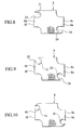
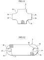
- Figs. 8 to 11 show various modifications of the fin 8.
- a clearance 26 is defined between the edge 8e of the fin 8 and the inner periphery 15a of the fluid communication passage 15
- another clearance 27 is defined between the edge 8f of the fin 8 and the inner periphery 15a of the fluid communication passage 15.
- the cutout parts 24, 25 are formed so that their widths are equal to diameters of the openings 20, 21, respectively. Owing to the above formation of the cutout parts 24, 25, it is possible to reduce the flowing resistance of the fluid, whereby the pressure drop in the chambers 15 can be reduced.
- the openings 20, 21 are arranged so that their parts intersect with the edges 8e, 8f of the fin 8.
- the fin 8 is provided, at two comers thereof, with arc-shaped recesses 28, 29 in place of the above openings 20, 21. These recesses 28, 29 are formed in a manner that some part of the fluid flows from the recess 28 toward the recess 29 directly and the other part of the fluid flows the recess 28, the edges 8e, 8f and the recess 29, in order.
- the operation and effects are similar to those of the fin 8 shown in Fig. 6.
- an oblong fin 8 is provided, at both ends 8a, 8b in the longitudinal direction, with circular openings 20, 21 and cutout parts 24, 25 connecting the openings 20, 21 with the edges 8e, 8f, respectively.
- the cutout parts 24, 25 are formed so as to extend from the openings 20, 21 to the edges 8e, 8f outwardly in the longitudinal direction of the fin 8. Owing to the formation of the cutout parts 24, 25, it becomes possible to make the fluid flow from the edge 8e to the edge 8f, whereby the heat exchange can be accomplished at both ends 8a, 8b of the fin 9.
Landscapes
- Engineering & Computer Science (AREA)
- Physics & Mathematics (AREA)
- Thermal Sciences (AREA)
- Mechanical Engineering (AREA)
- General Engineering & Computer Science (AREA)
- Heat-Exchange Devices With Radiators And Conduit Assemblies (AREA)
- Air-Conditioning For Vehicles (AREA)
Abstract
Description
Claims (9)
- A heat exchanger comprising:a plate-shaped heat exchanger unit shaped to be substantially rectangular in plan view, the plate-shaped heat exchanger unit having a first planar fluid communication chamber defined therein; anda flat fin shaped similarly to the first planar fluid communication chamber and accommodated in the first planar fluid communication chamber, the flat fin having a first end provided with a first recess and a second end opposing to the first end and provided with a second recess,wherein the flat fin is shaped so as to define a clearance between the first end and an inner periphery of the first planar fluid communication chamber, thereby allowing a first fluid, which has been introduced into the first planar fluid communication chamber through the first recess, to flow along an edge of the first end.
- The heat exchanger of claim 1, wherein the flat fin is shaped so as to define another clearance between the second end and the inner periphery of the first planar fluid communication chamber.
- The heat exchanger of claim 1, wherein the plate-shaped heat exchanger unit is provided with a first communication hole in communication with the first recess of the flat fin and a second communication hole in communication with the second recess of the flat fin.
- The heat exchanger of claim 3, wherein the first communication hole and the second communication hole are arranged at two diagonal comers of the plate-shaped heat exchanger unit, respectively.
- The heat exchanger of claim 1, wherein a shape of the first recess is substantially identical to a shape of the second recess.
- The heat exchanger of claim 5, wherein
the first recess comprises a first circular opening formed in the vicinity of the edge of the first end and a first cutout part formed to communicate the first circular opening with the edge of the first end, and
the second recess comprises a second circular opening formed in the vicinity of the edge of the second end and a second cutout part formed to communicate the second circular opening with the edge of the second end. - The heat exchanger of claim 6, wherein the first cutout part has its width substantially equal to a diameter of the first circular opening, while the second cutout part has its width substantially equal to a diameter of the second circular opening.
- The heat exchanger of claim 5, wherein the first recess is a first circular opening formed so that its part intersects with the edge of the first end of the flat fin, while the second recess is a second circular opening formed so that its part intersects with an edge of the second end of the flat fin.
- The heat exchanger of claim 1, wherein the plate-shaped heat exchanger unit has a second planar fluid communication chamber defined therein for a second fluid different from the first fluid.
Applications Claiming Priority (2)
| Application Number | Priority Date | Filing Date | Title |
|---|---|---|---|
| JP2003314309 | 2003-09-05 | ||
| JP2003314309A JP4338480B2 (en) | 2003-09-05 | 2003-09-05 | Heat exchanger |
Publications (2)
| Publication Number | Publication Date |
|---|---|
| EP1512930A2 true EP1512930A2 (en) | 2005-03-09 |
| EP1512930A3 EP1512930A3 (en) | 2007-11-14 |
Family
ID=34131908
Family Applications (1)
| Application Number | Title | Priority Date | Filing Date |
|---|---|---|---|
| EP04019971A Withdrawn EP1512930A3 (en) | 2003-09-05 | 2004-08-23 | Heat exchanger |
Country Status (3)
| Country | Link |
|---|---|
| US (1) | US7121331B2 (en) |
| EP (1) | EP1512930A3 (en) |
| JP (1) | JP4338480B2 (en) |
Cited By (7)
| Publication number | Priority date | Publication date | Assignee | Title |
|---|---|---|---|---|
| WO2007009615A1 (en) * | 2005-07-22 | 2007-01-25 | Behr Gmbh & Co. Kg | Plate element for a plate cooler |
| DE102006048305B4 (en) * | 2006-10-12 | 2011-06-16 | Modine Manufacturing Co., Racine | Plate heat exchanger |
| EP2236969A3 (en) * | 2009-03-13 | 2014-04-02 | Behr GmbH & Co. KG | Plate Heat exchanger for high exposure from thermal cycling |
| DE102012006346B4 (en) * | 2012-03-28 | 2014-09-18 | Modine Manufacturing Co. | heat exchangers |
| DE102013019478B3 (en) * | 2013-11-20 | 2015-01-22 | Modine Manufacturing Company | The heat exchanger assembly |
| DE102014212906A1 (en) * | 2014-07-03 | 2016-01-07 | Volkswagen Aktiengesellschaft | Intercooler with a plate heat exchanger |
| WO2026103977A1 (en) * | 2024-11-18 | 2026-05-21 | A.T. Haugg Beheer B.V. | Plate heat exchanger |
Families Citing this family (8)
| Publication number | Priority date | Publication date | Assignee | Title |
|---|---|---|---|---|
| JP4716094B2 (en) * | 2005-05-10 | 2011-07-06 | ソニー株式会社 | Route presenting device, route presenting method, and route presenting program |
| CN101432590B (en) * | 2006-04-14 | 2012-01-25 | 三菱电机株式会社 | Heat exchangers and refrigeration and air conditioning units |
| JP4812558B2 (en) * | 2006-08-15 | 2011-11-09 | 株式会社マーレ フィルターシステムズ | Manufacturing method of heat exchanger |
| US8550153B2 (en) * | 2008-10-03 | 2013-10-08 | Modine Manufacturing Company | Heat exchanger and method of operating the same |
| US9631876B2 (en) * | 2013-03-19 | 2017-04-25 | Mahle International Gmbh | Heat exchanger |
| US20150267966A1 (en) * | 2014-03-18 | 2015-09-24 | Metal Industries Research & Development Centre | Adaptable heat exchanger and fabrication method thereof |
| GB2552801B (en) * | 2016-08-10 | 2021-04-07 | Hs Marston Aerospace Ltd | Heat exchanger device |
| DE102016012842A1 (en) * | 2016-10-27 | 2018-05-03 | Linde Aktiengesellschaft | Plate heat exchanger |
Family Cites Families (13)
| Publication number | Priority date | Publication date | Assignee | Title |
|---|---|---|---|---|
| US2360123A (en) * | 1942-09-18 | 1944-10-10 | Gen Motors Corp | Oil cooler |
| JPS6113178U (en) * | 1984-06-28 | 1986-01-25 | 株式会社 土屋製作所 | housingless heat exchanger |
| US4815532A (en) * | 1986-02-28 | 1989-03-28 | Showa Aluminum Kabushiki Kaisha | Stack type heat exchanger |
| US4815534A (en) * | 1987-09-21 | 1989-03-28 | Itt Standard, Itt Corporation | Plate type heat exchanger |
| ES2127472T3 (en) * | 1994-04-12 | 1999-04-16 | Showa Aluminum Corp | STACKED DUPLEX HEAT EXCHANGER. |
| US6206089B1 (en) * | 1996-10-29 | 2001-03-27 | Denso Corporation | Heat exchanger and method for manufacturing the same |
| JP2000018848A (en) | 1998-04-29 | 2000-01-18 | Toyo Radiator Co Ltd | Plate heat exchanger |
| KR100389699B1 (en) * | 2001-01-17 | 2003-06-27 | 삼성공조 주식회사 | Water Cooling Heat Exchanger |
| US6341649B1 (en) * | 2001-02-12 | 2002-01-29 | Delphi Technologies, Inc. | Aluminum plate oil cooler |
| JP2003097890A (en) * | 2001-09-25 | 2003-04-03 | Denso Corp | Oil cooler |
| CA2372399C (en) * | 2002-02-19 | 2010-10-26 | Long Manufacturing Ltd. | Low profile finned heat exchanger |
| US20040003916A1 (en) * | 2002-07-03 | 2004-01-08 | Ingersoll-Rand Energy Systems, Inc. | Unit cell U-plate-fin crossflow heat exchanger |
| DE10304692A1 (en) * | 2003-02-06 | 2004-08-19 | Modine Manufacturing Co., Racine | Corrugated insert for a heat exchanger tube |
-
2003
- 2003-09-05 JP JP2003314309A patent/JP4338480B2/en not_active Expired - Fee Related
-
2004
- 2004-08-11 US US10/916,680 patent/US7121331B2/en not_active Expired - Fee Related
- 2004-08-23 EP EP04019971A patent/EP1512930A3/en not_active Withdrawn
Cited By (8)
| Publication number | Priority date | Publication date | Assignee | Title |
|---|---|---|---|---|
| WO2007009615A1 (en) * | 2005-07-22 | 2007-01-25 | Behr Gmbh & Co. Kg | Plate element for a plate cooler |
| DE102006048305B4 (en) * | 2006-10-12 | 2011-06-16 | Modine Manufacturing Co., Racine | Plate heat exchanger |
| EP2236969A3 (en) * | 2009-03-13 | 2014-04-02 | Behr GmbH & Co. KG | Plate Heat exchanger for high exposure from thermal cycling |
| DE102012006346B4 (en) * | 2012-03-28 | 2014-09-18 | Modine Manufacturing Co. | heat exchangers |
| DE102013019478B3 (en) * | 2013-11-20 | 2015-01-22 | Modine Manufacturing Company | The heat exchanger assembly |
| DE102014212906A1 (en) * | 2014-07-03 | 2016-01-07 | Volkswagen Aktiengesellschaft | Intercooler with a plate heat exchanger |
| WO2026103977A1 (en) * | 2024-11-18 | 2026-05-21 | A.T. Haugg Beheer B.V. | Plate heat exchanger |
| DE102024133638A1 (en) * | 2024-11-18 | 2026-05-21 | A.T. Haugg Beheer B.V. | Plate heat exchanger |
Also Published As
| Publication number | Publication date |
|---|---|
| EP1512930A3 (en) | 2007-11-14 |
| JP2005083622A (en) | 2005-03-31 |
| US20050082048A1 (en) | 2005-04-21 |
| US7121331B2 (en) | 2006-10-17 |
| JP4338480B2 (en) | 2009-10-07 |
Similar Documents
| Publication | Publication Date | Title |
|---|---|---|
| US7121331B2 (en) | Heat exchanger | |
| JP7480487B2 (en) | Heat exchanger | |
| US7044205B2 (en) | Layered heat exchangers | |
| US6070428A (en) | Stack type evaporator | |
| JP2002506196A (en) | 3-circuit plate heat exchanger | |
| US6920916B2 (en) | Layered heat exchangers | |
| US7174953B2 (en) | Stacking-type, multi-flow, heat exchanger | |
| JP4190289B2 (en) | Heat exchanger | |
| AU2002234898A1 (en) | Heat exchanger | |
| JPH10292995A (en) | Stacked heat exchanger | |
| EP1369656A2 (en) | Laminate-type heat exchanger | |
| JPH07243788A (en) | Heat exchanger | |
| CN113574332B (en) | Heat exchanger | |
| JP7576944B2 (en) | Heat exchanger | |
| JPH0894274A (en) | Stacked heat exchanger | |
| JP4731212B2 (en) | Heat exchanger | |
| KR100528997B1 (en) | Multilayer Heat Exchanger | |
| WO2017195588A1 (en) | Stack type heat exchanger | |
| KR100350949B1 (en) | Laminate type heat exchanger for vehicle | |
| JPH06137713A (en) | Stacked heat exchanger | |
| JPH03186194A (en) | Laminar heat exchanger | |
| JPH0674681A (en) | Heat exchanger header | |
| KR101082473B1 (en) | Heat exchanger | |
| KR100479849B1 (en) | heat transmitter | |
| JPH081417Y2 (en) | Multilayer evaporator |
Legal Events
| Date | Code | Title | Description |
|---|---|---|---|
| PUAI | Public reference made under article 153(3) epc to a published international application that has entered the european phase |
Free format text: ORIGINAL CODE: 0009012 |
|
| AK | Designated contracting states |
Kind code of ref document: A2 Designated state(s): AT BE BG CH CY CZ DE DK EE ES FI FR GB GR HU IE IT LI LU MC NL PL PT RO SE SI SK TR |
|
| AX | Request for extension of the european patent |
Extension state: AL HR LT LV MK |
|
| PUAL | Search report despatched |
Free format text: ORIGINAL CODE: 0009013 |
|
| AK | Designated contracting states |
Kind code of ref document: A3 Designated state(s): AT BE BG CH CY CZ DE DK EE ES FI FR GB GR HU IE IT LI LU MC NL PL PT RO SE SI SK TR |
|
| AX | Request for extension of the european patent |
Extension state: AL HR LT LV MK |
|
| 17P | Request for examination filed |
Effective date: 20080130 |
|
| 17Q | First examination report despatched |
Effective date: 20080229 |
|
| AKX | Designation fees paid |
Designated state(s): DE FR GB |
|
| GRAP | Despatch of communication of intention to grant a patent |
Free format text: ORIGINAL CODE: EPIDOSNIGR1 |
|
| STAA | Information on the status of an ep patent application or granted ep patent |
Free format text: STATUS: THE APPLICATION IS DEEMED TO BE WITHDRAWN |
|
| 18D | Application deemed to be withdrawn |
Effective date: 20100129 |