EP1512898A1 - Vibration suppressing clamp for pipe or the like - Google Patents
Vibration suppressing clamp for pipe or the like Download PDFInfo
- Publication number
- EP1512898A1 EP1512898A1 EP04020753A EP04020753A EP1512898A1 EP 1512898 A1 EP1512898 A1 EP 1512898A1 EP 04020753 A EP04020753 A EP 04020753A EP 04020753 A EP04020753 A EP 04020753A EP 1512898 A1 EP1512898 A1 EP 1512898A1
- Authority
- EP
- European Patent Office
- Prior art keywords
- seat
- pipe
- vibration
- base
- flexible wall
- Prior art date
- Legal status (The legal status is an assumption and is not a legal conclusion. Google has not performed a legal analysis and makes no representation as to the accuracy of the status listed.)
- Withdrawn
Links
- 230000001629 suppression Effects 0.000 claims abstract description 66
- 230000008878 coupling Effects 0.000 claims description 8
- 238000010168 coupling process Methods 0.000 claims description 8
- 238000005859 coupling reaction Methods 0.000 claims description 8
- 238000000465 moulding Methods 0.000 claims description 8
- 239000012260 resinous material Substances 0.000 description 13
- 230000035939 shock Effects 0.000 description 6
- 230000000694 effects Effects 0.000 description 3
- 239000000463 material Substances 0.000 description 3
- 230000005540 biological transmission Effects 0.000 description 2
- 230000004048 modification Effects 0.000 description 2
- 238000012986 modification Methods 0.000 description 2
- 230000003014 reinforcing effect Effects 0.000 description 2
- 229920002725 thermoplastic elastomer Polymers 0.000 description 2
- 238000010521 absorption reaction Methods 0.000 description 1
- 230000002238 attenuated effect Effects 0.000 description 1
- 230000002708 enhancing effect Effects 0.000 description 1
- 230000001747 exhibiting effect Effects 0.000 description 1
- 239000000446 fuel Substances 0.000 description 1
- 230000001771 impaired effect Effects 0.000 description 1
- 230000002401 inhibitory effect Effects 0.000 description 1
- 238000003780 insertion Methods 0.000 description 1
- 230000037431 insertion Effects 0.000 description 1
- 230000000630 rising effect Effects 0.000 description 1
- 238000003466 welding Methods 0.000 description 1
Images


Classifications
-
- F—MECHANICAL ENGINEERING; LIGHTING; HEATING; WEAPONS; BLASTING
- F16—ENGINEERING ELEMENTS AND UNITS; GENERAL MEASURES FOR PRODUCING AND MAINTAINING EFFECTIVE FUNCTIONING OF MACHINES OR INSTALLATIONS; THERMAL INSULATION IN GENERAL
- F16L—PIPES; JOINTS OR FITTINGS FOR PIPES; SUPPORTS FOR PIPES, CABLES OR PROTECTIVE TUBING; MEANS FOR THERMAL INSULATION IN GENERAL
- F16L3/00—Supports for pipes, cables or protective tubing, e.g. hangers, holders, clamps, cleats, clips, brackets
- F16L3/22—Supports for pipes, cables or protective tubing, e.g. hangers, holders, clamps, cleats, clips, brackets specially adapted for supporting a number of parallel pipes at intervals
- F16L3/223—Supports for pipes, cables or protective tubing, e.g. hangers, holders, clamps, cleats, clips, brackets specially adapted for supporting a number of parallel pipes at intervals each support having one transverse base for supporting the pipes
-
- F—MECHANICAL ENGINEERING; LIGHTING; HEATING; WEAPONS; BLASTING
- F16—ENGINEERING ELEMENTS AND UNITS; GENERAL MEASURES FOR PRODUCING AND MAINTAINING EFFECTIVE FUNCTIONING OF MACHINES OR INSTALLATIONS; THERMAL INSULATION IN GENERAL
- F16L—PIPES; JOINTS OR FITTINGS FOR PIPES; SUPPORTS FOR PIPES, CABLES OR PROTECTIVE TUBING; MEANS FOR THERMAL INSULATION IN GENERAL
- F16L3/00—Supports for pipes, cables or protective tubing, e.g. hangers, holders, clamps, cleats, clips, brackets
- F16L3/08—Supports for pipes, cables or protective tubing, e.g. hangers, holders, clamps, cleats, clips, brackets substantially surrounding the pipe, cable or protective tubing
- F16L3/12—Supports for pipes, cables or protective tubing, e.g. hangers, holders, clamps, cleats, clips, brackets substantially surrounding the pipe, cable or protective tubing comprising a member substantially surrounding the pipe, cable or protective tubing
- F16L3/13—Supports for pipes, cables or protective tubing, e.g. hangers, holders, clamps, cleats, clips, brackets substantially surrounding the pipe, cable or protective tubing comprising a member substantially surrounding the pipe, cable or protective tubing and engaging it by snap action
-
- F—MECHANICAL ENGINEERING; LIGHTING; HEATING; WEAPONS; BLASTING
- F16—ENGINEERING ELEMENTS AND UNITS; GENERAL MEASURES FOR PRODUCING AND MAINTAINING EFFECTIVE FUNCTIONING OF MACHINES OR INSTALLATIONS; THERMAL INSULATION IN GENERAL
- F16L—PIPES; JOINTS OR FITTINGS FOR PIPES; SUPPORTS FOR PIPES, CABLES OR PROTECTIVE TUBING; MEANS FOR THERMAL INSULATION IN GENERAL
- F16L55/00—Devices or appurtenances for use in, or in connection with, pipes or pipe systems
- F16L55/02—Energy absorbers; Noise absorbers
- F16L55/033—Noise absorbers
- F16L55/035—Noise absorbers in the form of specially adapted hangers or supports
Definitions
- the present invention relates to a clamp for holding elongated objects, such as pipes, wire harness, fuel lines, or hydraulic brake lines, to a vehicle body, for example, and more particularly to a vibration suppressing clamp constructed so that vibration is not transmitted from the object to the vehicle body, and/or so that vibration is not transmitted from the vehicle body to the object.
- elongated objects such as pipes, wire harness, fuel lines, or hydraulic brake lines
- a vibration suppressing clamp constructed so that vibration is not transmitted from the object to the vehicle body, and/or so that vibration is not transmitted from the vehicle body to the object.
- Patent Literature 1 discloses a clamp for pipes, and for preventing rattle noises that accompany vibration.
- the clamp comprises a base and a pipe holder supported by the base.
- the pipe holder comprises curved walls that form concavities for accepting pipes, and elastic holding pieces, extending diagonally from tip parts of the curved walls in the direction of the concavities, for pressing side surfaces of pipes accommodated in the curved walls.
- the inner wall surfaces are covered with a soft shock- absorbing resinous material that directly contacts pipes held by the curved walls so that rattle noise is absorbed.
- Patent Literature 2 a counterpart of U.S. Patent No. 5,954,300 issued September 21, 1999, discloses a vibration suppressing clamp for pipes designed so that vibration is not transmitted from pipes to a vehicle body, for example, and/or so that vibration is not transmitted from a vehicle body to pipes.
- the vibration suppressing clamp effects noise suppression by the deployment of vibration attenuating material between a pipe holder consisting of a hard resinous material and a base consisting of a hard resinous material for supporting the pipe holder.
- Patent Literature 3 discloses a vibration suppressing clamp for pipes, designed so that vibration is not transmitted from pipes to a vehicle body, for example, and/or so that vibration is not transmitted from a vehicle body to pipes.
- the vibration suppressing clamp is intended to suppress rattle noises accompanying vibration, and effects noise suppression by the deployment of a vibration suppression member between a pipe holder consisting of a hard resinous material and a base consisting of a hard resinous material for supporting the pipe holder.
- Patent Literature 1 directly holds pipes with a soft shock-absorbing (vibration suppressing) resinous material, so the vibration suppression effect can be enhanced, but in order to raise the vibration suppression effect, it is necessary to make the vibration suppressing resinous material thick.
- the vibration suppression member is soft, however, and if it is made thick, the pipe holding force will weaken, so there is a danger that pipes will wobble inside the curved walls. There is also a danger of the vibration suppressing resinous material peeling away due to strong forces on pipes in the axial direction. Should a pipe compress the vibration suppression member due to shock, there is a danger that the vibration suppression member will be excessively deformed and fail, because there is nowhere for the material to escape.
- the vibration suppressing clamp described in Patent Literature 2 and Patent Literature 3 unlike the clamp in Patent Literature 1, has no vibration suppression member between the pipe holder and pipes, and exhibits low vibration absorbing effect compared to clamps that hold pipes directly with a vibration suppression member as in Patent Literature 1.
- an object of the present invention is to provide an improved vibration suppressing clamp for pipes in which enhanced vibration suppression is realized while holding pipes with sufficient holding force, and in which the vibration suppression member will not be excessively deformed even if compressed by a pipe due to shock.
- a vibration suppressing clamp for pipes comprises a base with a pipe holder supported by the base, the pipe holder comprising a seat that forms a bottom surface for supporting a pipe, and a pair of opposite walls rising from side edges of the seat for forming a space that accommodates the pipe in cooperation with the seat.
- at least one of the walls may be capable of flexing relative to the pipe accommodating space and relative to a space between the flexible wall and an adjacent rigid wall, and may have a tip with a holding piece that presses a side surface of a pipe in the pipe holder.
- the seat and lower portion of the flexible wall are covered by a vibration suppression member the vibration suppression member enters in the space between the flexible wall of the adjacent rigid wall.
- the seat has a hole or holes that extend through the base so that portions of the vibration suppression member deformed by impact on a pipe in the pipe holder can retract into the holes.
- a clamp 1 (constituting a primary molding) comprises a base 3, and pipe holders 5, 6, 7, and 9 supported by the base.
- the base 3 comprises a securing unit 10 for securing the base to a stud, for example, attached to a vehicle body or the like.
- the securing unit 10 is deployed between a conventional pipe holder 9 and a pipe holder 7 relating to the present invention.
- the base 3, pipe holders 5 to 9, and securing unit 10 are preferably molded integrally of a hard resinous material exhibiting high rigidity.
- the securing unit 10 may be something other than a stud securing unit, and may cooperate with an anchor clip which is inserted into and engages with an attachment hole, for example.
- Conventional pipe holders 5, 6, and 9 and the pipe holder 7 relating to the present invention may be formed to accommodate a variety of elongated objects. The number, size, and shape of the pipe holders can be selected discretionally to conform to the objects being held.
- Each of the conventional pipe holders 5, 6, and 9 comprises a curved wall 13 for forming a space 11 to accommodate an elongated object such as a pipe, and an elastic holding piece 14, which extends diagonally from the tip of the curved wall 13 (upper end thereof in Fig. 2) toward the object accommodating space 11, for pressing down a side surface of the object.
- the pipe holders 5 to 9 all except the pipe holder 7 may be conventional pipe holders comprising a curved wall 13 and an elastic holding piece 14. A pipe is pushed down toward the elastic holding piece 14 and into the space 11, and the side surface of the pipe is pressed against by the tip of the elastic holding piece 14, so that the pipe is held in the space 11.
- Such pipe holders 5, 6, and 9 are well known, and no further description thereof is given here.
- the pipe holder 7 is a pipe holder relating to the present invention.
- the pipe holder 7 comprises a seat 15 integral with the base 3 and forming a bottom surface for supporting an elongated object, and a pair of walls 18, which rise from two side edges of the seat 15 to form a space 17 for accommodating an object in cooperation with the seat.
- At least one of the walls 18 is a thin flexible wall that can flex relative to the space 17. In the embodiment shown, both of the walls 18 are flexible walls, but only one may be a flexible wall.
- each wall 18 there is an elastic holding piece 19, extending diagonally toward the space 17, for pressing down on the side surface of an elongated object accommodated in space 17.
- the elastic holding piece 19 may be provided on one of the walls 18 or on both walls according to the holding force necessary for the object being held.
- the seat 15 has first ribs 21 which extend in the longitudinal direction of the object and second ribs 22 which cross the first ribs 21.
- the first ribs 21 are preferably provided as three ribs, namely one in the middle and two at side edges
- the second ribs 22, which cross the first ribs 21, are also preferably provided as three ribs, namely one in the middle and two at side edges.
- the portions of the base where the first ribs 21 and second ribs 22 are absent are formed as through-holes 23 which extend throgh the seat 15 and then pass through the base 3.
- the through-holes 23 form spaces for accepting deformed portions of a vibration suppression member, preferably consisting of a soft resinous material (described below), which deform due to shock or the like, that is to say, holes 23 form spaces into which deformed portions of the vibration suppression member can retract.
- the seat 15 has a bottom surface formed by the pluralities of first ribs 21 and second ribs 22.
- the bottom surface of the seat 15 is curved so as to correspond to the curved side surface of a pipe and is formed, as shown in Fig. 2, thicker toward the top, so as to make the seat 15 higher at side edges.
- the base 3 has third ribs 25 which cross the first ribs 21.
- the third rib 25 in the center of the base is formed at the same position and to the same width as the center rib of the second ribs 22, and the third ribs 25 at the sides of the base 3 are formed farther to the outside than the second ribs 22 at the sides of the seat 15.
- the pipe holder 6 and the securing unit 10 are integrally formed on the base 3, adjacent to the pipe holder 7, the pipe holder 6 and the securing unit 10 are integrally formed.
- Rigid walls 26 and 27 are formed in the pipe holder 6 and the securing unit 10, adjacent, respectively, to each of the flexible walls 18 of the pipe holder 7.
- the flexible walls 18 are coupled to the rigid walls 26 by thin coupling pieces 29, such that the vibration suppression effect of the flexible walls 18 can be maintained high, i.e., without inhibiting the attenuation or absorption of vibration by the flexible walls 18.
- the coupling pieces 29 also function as anchors for the vibration suppression member (described below) which enters the space between a flexible wall 18 and a rigid wall 26 or 27, reinforcing the securing of the vibration suppression member that is bonded to the pipe holder 7, and preventing peeling due to lateral shifting.
- the coupling pieces 29, moreover, can prevent the flexible walls 18 from excessively deflecting when a pipe is inserted into the space 17.
- the two side surfaces of the seat 15 and the portions of the flexible walls 18 adjacent to the seat 15 are formed shorter in the width direction than the base 3 and the rigid walls 26 and 27 and of the pipe holder 6 (that is, in the length direction of the pipe being held in the pipe holders, which is the up and down direction in Fig. 1), so as to obtain room for covering with the vibration suppression member.
- the upper portions of the flexible walls 18 are not covered by the vibration suppression member, so they are formed to the same width as that of the rigid wall 26 and 27 and of the pipe holder 6 and the base 3.
- a plurality of stud engagement pawls 30 are formed in the stud axis direction in a stud accepting hole.
- opposed spring pieces 31 which elastically contact the vehicle body are provided at the upper portion of the securing unit 10. These spring pieces elastically contact a vehicle body or other member being attached thereto and enhance the engagement force of the stud engagement pawls 30 into the circumferential grooves or threads of the stud.
- a vibration suppression member 33 preferably consisting of soft resinous material, so that a vibration suppressing clamp 2 relating to the present invention is obtained as a secondary molding.
- the seat 15 of the pipe holder 7 and the portions of the flexible walls 18 adjacent to the seat are covered by the vibration suppression member 33.
- This covering with the vibration suppression member 33 can be performed by so-called two-color molding or insert molding, and the number of parts and number of assembly operations can be reduced.
- the vibration suppression member 33 is preferably selected from soft resinous materials that will prevent shifting in the axial direction of a pipe being held.
- a typical material is a thermoplastic elastomer (TPE), for example.
- TPE thermoplastic elastomer
- the covering, in the pipe holder 7 of the primary-molding clamp 1, can be performed using a mold which encloses the seat 15 and the lower portions of the flexible walls 18.
- a soft resinous material suitable for the vibration suppression member is melted, and then hardened inside the mold.
- the vibration suppression member 33 encloses the first ribs 21 and second ribs 22 of the seat 15, enters the through-holes between the first ribs 21 and the second ribs 22, encloses lower portions of the flexible walls 18, enters the spaces adjacent to the rigid walls 26 and 27, and forms a curved surface 34, on the upper side of the seat 15, in a shape conforming to the curvature of the side surface of a pipe, so that a pipe accepted into the object accommodating space 17 is supported by thick portions of the member 33, and high vibration suppression effect is obtained.
- the vibration suppression member 33 does not cover upper portions thereof, so the flexibility of the upper wall portions will not be impaired.
- the vibration suppression member 33 preferably fills the space between the flexible walls 18 and the rigid walls 26 and 27 and also surrounds the coupling pieces 29 shown in Figs. 2 and 3.
- the vibration suppression member 33 may leave upper portions of the spaces between the flexible walls 18 and the rigid walls 26 and 27 open. Coupling pieces 29 function as anchors for the vibration suppression member 33, reinforcing the securing of the vibration suppression member bonded to the pipe holder 7, and peeling of the vibration suppression member is prevented.
- the vibration suppression member 33 which encloses the first ribs 21 and the second ribs 22, is strongly secured to the seat 15. Should the vibration suppression member 33 on the upper side of the seat 15 be compressed downward by shock toward a pipe, it will move downward as it is being deformed, into the through-holes 23, so that a place for the vibration suppression member 33 to retract is provided, and excessive deformation of the vibration suppression member 33 is prevented. Accordingly, failure of the vibration suppression member 33 can be prevented.
- At least one vibration suppression member-equipped pipe holder 7 is provided. Although in this embodiment, there is but one vibration suppression member-equipped pipe holder 7, there may be a plurality thereof.
- Fig. 9 shows the condition of the vibration suppressing clamp 2 with a pipe 35 held in the pipe holder 7, and pipes 37, 38, and 39 held in the other pipe holders 5, 6, and 9, respectively.
- the pipes 35 and 37 to 39 may also be held by other vibration suppressing clamps 2 at other positions.
- the pipe 35 held in the pipe holder 7 is held such that contact is made with the vibration suppression member 33 by a side surface on a lower portion thereof.
- the tips of the elastic holding pieces 19 are in contact therewith.
- almost none of the vibration of the pipe 35 is transmitted to the base 3, and, similarly, almost no vibration is transmitted from the base 3 to the pipe 35, so that enhanced vibration suppression can be realized.
- the flexible walls 18 which support the elastic holding pieces 19, furthermore, are not directly coupled to the securing unit 10 or the pipe holder 6.
- the vibration suppression member 33 is present between the flexible walls 18 and the rigid walls 26 and 27 of the pipe holder 6 and the securing unit 10. As a consequence, the transmission of vibration from the elastic holding pieces 19 to the adjacent pipe holder 6 or securing unit 10 and the transmission of vibration from the pipe holder 6 and securing unit 10 to the elastic holding pieces 19 are prevented, and vibration suppression is realized.
- the curved bottom surface of the seat 15 functions as a rigidity-exhibiting core for the vibration suppression member 33, and strong holding forces are maintained.
- Fig. 10 shows how pipes 35 and 37 to 39 may be attached to a vehicle body 41 by the vibration suppressing clamp 2.
- a stud 43 having a plurality of circumferential grooves 42, and the securing unit 10 is secured to the stud 43.
- the pipe 35 attached in this manner to the vehicle body 41 is sometimes subjected to shock forces when the vehicle is moving Due to such shock, the pipe sometimes strongly compresses the vibration suppression member, causing the vibration suppression member to be deformed. In cases such as this, deformed portions of the vibration suppression member can retract into the through-holes 23 in the seat 15, and excessive deformation can be prevented.
Landscapes
- Engineering & Computer Science (AREA)
- General Engineering & Computer Science (AREA)
- Mechanical Engineering (AREA)
- Supports For Pipes And Cables (AREA)
- Clamps And Clips (AREA)
- Connection Of Plates (AREA)
- Vibration Prevention Devices (AREA)
Abstract
Description
- The present invention relates to a clamp for holding elongated objects, such as pipes, wire harness, fuel lines, or hydraulic brake lines, to a vehicle body, for example, and more particularly to a vibration suppressing clamp constructed so that vibration is not transmitted from the object to the vehicle body, and/or so that vibration is not transmitted from the vehicle body to the object. Although the invention is applicable to a variety of elongated objects, for simplicity of description all such objects will be referred to hereinafter as an object or a pipe without limitation.
- Laid-Open Utility Model Application [JIKKAI] No. H4-44581/1992, gazette (Patent Literature 1) discloses a clamp for pipes, and for preventing rattle noises that accompany vibration. The clamp comprises a base and a pipe holder supported by the base. The pipe holder comprises curved walls that form concavities for accepting pipes, and elastic holding pieces, extending diagonally from tip parts of the curved walls in the direction of the concavities, for pressing side surfaces of pipes accommodated in the curved walls. The inner wall surfaces are covered with a soft shock- absorbing resinous material that directly contacts pipes held by the curved walls so that rattle noise is absorbed.
- Laid-Open Patent Application [TOKKAI] No. H9-184580/1997 (Patent Literature 2), a counterpart of U.S. Patent No. 5,954,300 issued September 21, 1999, discloses a vibration suppressing clamp for pipes designed so that vibration is not transmitted from pipes to a vehicle body, for example, and/or so that vibration is not transmitted from a vehicle body to pipes. The vibration suppressing clamp effects noise suppression by the deployment of vibration attenuating material between a pipe holder consisting of a hard resinous material and a base consisting of a hard resinous material for supporting the pipe holder.
- Laid-Open Patent Application [TOKKAI] No. H11-304055/1999, gazette (Patent Literature 3) discloses a vibration suppressing clamp for pipes, designed so that vibration is not transmitted from pipes to a vehicle body, for example, and/or so that vibration is not transmitted from a vehicle body to pipes. The vibration suppressing clamp is intended to suppress rattle noises accompanying vibration, and effects noise suppression by the deployment of a vibration suppression member between a pipe holder consisting of a hard resinous material and a base consisting of a hard resinous material for supporting the pipe holder.
- The clamp described in
Patent Literature 1 directly holds pipes with a soft shock-absorbing (vibration suppressing) resinous material, so the vibration suppression effect can be enhanced, but in order to raise the vibration suppression effect, it is necessary to make the vibration suppressing resinous material thick. The vibration suppression member is soft, however, and if it is made thick, the pipe holding force will weaken, so there is a danger that pipes will wobble inside the curved walls. There is also a danger of the vibration suppressing resinous material peeling away due to strong forces on pipes in the axial direction. Should a pipe compress the vibration suppression member due to shock, there is a danger that the vibration suppression member will be excessively deformed and fail, because there is nowhere for the material to escape. - The vibration suppressing clamp described in
Patent Literature 2 andPatent Literature 3, unlike the clamp inPatent Literature 1, has no vibration suppression member between the pipe holder and pipes, and exhibits low vibration absorbing effect compared to clamps that hold pipes directly with a vibration suppression member as inPatent Literature 1. - Accordingly, an object of the present invention is to provide an improved vibration suppressing clamp for pipes in which enhanced vibration suppression is realized while holding pipes with sufficient holding force, and in which the vibration suppression member will not be excessively deformed even if compressed by a pipe due to shock.
- In one embodiment of the invention, a vibration suppressing clamp for pipes comprises a base with a pipe holder supported by the base, the pipe holder comprising a seat that forms a bottom surface for supporting a pipe, and a pair of opposite walls rising from side edges of the seat for forming a space that accommodates the pipe in cooperation with the seat. Specifically, at least one of the walls may be capable of flexing relative to the pipe accommodating space and relative to a space between the flexible wall and an adjacent rigid wall, and may have a tip with a holding piece that presses a side surface of a pipe in the pipe holder. The seat and lower portion of the flexible wall are covered by a vibration suppression member the vibration suppression member enters in the space between the flexible wall of the adjacent rigid wall. The seat has a hole or holes that extend through the base so that portions of the vibration suppression member deformed by impact on a pipe in the pipe holder can retract into the holes.
- The invention will be further described in conjunction with the accompanying drawings which illustrate a preferred (best mode) embodiment, and wherein:
- Fig. 1 is a plan view of a clamp relating to a first embodiment of the present invention before covering with a vibration suppression member;
- Fig. 2 is a front elevation view of the clamp shown in Fig. 1;
- Fig. 3 is a bottom plan view of the clamp shown in Fig. 1;
- Fig. 4 (A) is a left side elevation view of the clamp shown in Fig. 1;
- and 4(B) is a right side elevation view of the clamp shown in Fig. 1;
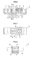
- Fig. 5 is a plan view of a vibration suppressing clamp relating to an embodiment of the present invention after the clamp shown in Fig. 1 has been covered with the vibration suppression member;
- Fig. 6 is a front elevation view of the vibration suppressing clamp shown in Fig. 5;
- Fig. 6A is a view similar to Fig. 6, showing a modification;
- Fig. 7 is a bottom plan view of the vibration suppressing clamp shown in Fig. 5;
- Fig. 8 is a sectional view, in the VIII-VIII plane, of the vibration suppressing clamp shown in Fig. 6;
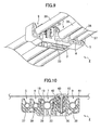
- Fig. 9 is a perspective view showing a plurality of pipes supported by the vibration suppressing clamp shown in Fig. 5; and
- Fig. 10 is a sectional view of a vibration suppressing clamp shown in Fig. 9 secured to a vehicle body.
-
- A vibration suppressing clamp for elongated objects relating to one embodiment of the present invention will now be described with reference to the drawings.
- A clamp 1 (constituting a primary molding) comprises a
base 3, andpipe holders base 3 comprises asecuring unit 10 for securing the base to a stud, for example, attached to a vehicle body or the like. In the example shown, thesecuring unit 10 is deployed between aconventional pipe holder 9 and apipe holder 7 relating to the present invention. Thebase 3,pipe holders 5 to 9, and securingunit 10 are preferably molded integrally of a hard resinous material exhibiting high rigidity. The securingunit 10 may be something other than a stud securing unit, and may cooperate with an anchor clip which is inserted into and engages with an attachment hole, for example.Conventional pipe holders pipe holder 7 relating to the present invention may be formed to accommodate a variety of elongated objects. The number, size, and shape of the pipe holders can be selected discretionally to conform to the objects being held. - Each of the
conventional pipe holders curved wall 13 for forming a space 11 to accommodate an elongated object such as a pipe, and anelastic holding piece 14, which extends diagonally from the tip of the curved wall 13 (upper end thereof in Fig. 2) toward the object accommodating space 11, for pressing down a side surface of the object. Of thepipe holders 5 to 9, all except thepipe holder 7 may be conventional pipe holders comprising acurved wall 13 and anelastic holding piece 14. A pipe is pushed down toward theelastic holding piece 14 and into the space 11, and the side surface of the pipe is pressed against by the tip of theelastic holding piece 14, so that the pipe is held in the space 11.Such pipe holders - The
pipe holder 7 is a pipe holder relating to the present invention. Thepipe holder 7 comprises aseat 15 integral with thebase 3 and forming a bottom surface for supporting an elongated object, and a pair ofwalls 18, which rise from two side edges of theseat 15 to form aspace 17 for accommodating an object in cooperation with the seat. At least one of thewalls 18 is a thin flexible wall that can flex relative to thespace 17. In the embodiment shown, both of thewalls 18 are flexible walls, but only one may be a flexible wall. - At a tip portion of each
wall 18 there is anelastic holding piece 19, extending diagonally toward thespace 17, for pressing down on the side surface of an elongated object accommodated inspace 17. Theelastic holding piece 19 may be provided on one of thewalls 18 or on both walls according to the holding force necessary for the object being held. When an object such as a pipe is inserted inspace 17, that insertion is made easy, because theelastic holding piece 19 can flex to the outside together with theflexible wall 18, and then return to its original position to hold the pipe securely. Furthermore, by having theelastic holding piece 19 formed on theflexible wall 18, vibration transmitted to theelastic holding piece 19 will be attenuated by the flexible wall and markedly absorbed, thus enhancing the vibration suppression effect. - Holes are formed in the
seat 15 which extend through theseat 15 and thebase 3. In the embodiment shown, spaces between a plurality of ribs formed in a lattice shape are formed as through-holes. In the embodiment, theseat 15 hasfirst ribs 21 which extend in the longitudinal direction of the object andsecond ribs 22 which cross thefirst ribs 21. As shown in Fig. 1 and Fig. 3, thefirst ribs 21 are preferably provided as three ribs, namely one in the middle and two at side edges, and thesecond ribs 22, which cross thefirst ribs 21, are also preferably provided as three ribs, namely one in the middle and two at side edges. The portions of the base where thefirst ribs 21 andsecond ribs 22 are absent are formed as through-holes 23 which extend throgh theseat 15 and then pass through thebase 3. The through-holes 23 form spaces for accepting deformed portions of a vibration suppression member, preferably consisting of a soft resinous material (described below), which deform due to shock or the like, that is to say,holes 23 form spaces into which deformed portions of the vibration suppression member can retract. Theseat 15 has a bottom surface formed by the pluralities offirst ribs 21 andsecond ribs 22. - The bottom surface of the
seat 15 is curved so as to correspond to the curved side surface of a pipe and is formed, as shown in Fig. 2, thicker toward the top, so as to make theseat 15 higher at side edges. In the portion of thebase 3 that is continuous with theseat 15, thebase 3 hasthird ribs 25 which cross thefirst ribs 21. In the embodiment shown, thethird rib 25 in the center of the base is formed at the same position and to the same width as the center rib of thesecond ribs 22, and thethird ribs 25 at the sides of thebase 3 are formed farther to the outside than thesecond ribs 22 at the sides of theseat 15. - On the
base 3, adjacent to thepipe holder 7, thepipe holder 6 and the securingunit 10 are integrally formed.Rigid walls pipe holder 6 and the securingunit 10, adjacent, respectively, to each of theflexible walls 18 of thepipe holder 7. There are spaces between theflexible walls 18 and therigid walls flexible walls 18 can flex both toward therigid walls space 17. When a pipe is pushed into thepipe holder 7, for example, theflexible walls 18 flex toward therigid walls space 17, so that the pipe is held with theelastic holding pieces 19 engaging the side surface of the pipe to prevent pullout. - The
flexible walls 18 are coupled to therigid walls 26 bythin coupling pieces 29, such that the vibration suppression effect of theflexible walls 18 can be maintained high, i.e., without inhibiting the attenuation or absorption of vibration by theflexible walls 18. Thecoupling pieces 29 also function as anchors for the vibration suppression member (described below) which enters the space between aflexible wall 18 and arigid wall pipe holder 7, and preventing peeling due to lateral shifting. Thecoupling pieces 29, moreover, can prevent theflexible walls 18 from excessively deflecting when a pipe is inserted into thespace 17. - In the
primary molding clamp 1 shown in Figs. 1 to 4, the two side surfaces of theseat 15 and the portions of theflexible walls 18 adjacent to theseat 15 are formed shorter in the width direction than thebase 3 and therigid walls flexible walls 18 are not covered by the vibration suppression member, so they are formed to the same width as that of therigid wall pipe holder 6 and thebase 3. - In the securing
unit 10, in order to accept a bolt stud or circumferentially grooved stud, for example, welded to a vehicle body, for example, a plurality ofstud engagement pawls 30 are formed in the stud axis direction in a stud accepting hole. As shown in Fig. 2, opposedspring pieces 31 which elastically contact the vehicle body are provided at the upper portion of the securingunit 10. These spring pieces elastically contact a vehicle body or other member being attached thereto and enhance the engagement force of thestud engagement pawls 30 into the circumferential grooves or threads of the stud. - Portions of the
pipe holder 7 of theprimary molding clamp 1 are covered, as shown in Figs. 5 to 8, with avibration suppression member 33 preferably consisting of soft resinous material, so that avibration suppressing clamp 2 relating to the present invention is obtained as a secondary molding. In Figs. 5 to 8, theseat 15 of thepipe holder 7 and the portions of theflexible walls 18 adjacent to the seat (i.e. the lower portions thereof) are covered by thevibration suppression member 33. This covering with thevibration suppression member 33 can be performed by so-called two-color molding or insert molding, and the number of parts and number of assembly operations can be reduced. Thevibration suppression member 33 is preferably selected from soft resinous materials that will prevent shifting in the axial direction of a pipe being held. A typical material is a thermoplastic elastomer (TPE), for example. The covering, in thepipe holder 7 of the primary-molding clamp 1, can be performed using a mold which encloses theseat 15 and the lower portions of theflexible walls 18. A soft resinous material suitable for the vibration suppression member is melted, and then hardened inside the mold. Thevibration suppression member 33 encloses thefirst ribs 21 andsecond ribs 22 of theseat 15, enters the through-holes between thefirst ribs 21 and thesecond ribs 22, encloses lower portions of theflexible walls 18, enters the spaces adjacent to therigid walls curved surface 34, on the upper side of theseat 15, in a shape conforming to the curvature of the side surface of a pipe, so that a pipe accepted into theobject accommodating space 17 is supported by thick portions of themember 33, and high vibration suppression effect is obtained. - In a preferred embodiment, although lower portions of the
flexible walls 18 are enclosed by thevibration suppression member 33, thevibration suppression member 33 does not cover upper portions thereof, so the flexibility of the upper wall portions will not be impaired. Thevibration suppression member 33 preferably fills the space between theflexible walls 18 and therigid walls coupling pieces 29 shown in Figs. 2 and 3. However, as shown in the modification of Fig. 6A, thevibration suppression member 33 may leave upper portions of the spaces between theflexible walls 18 and therigid walls pieces 29 function as anchors for thevibration suppression member 33, reinforcing the securing of the vibration suppression member bonded to thepipe holder 7, and peeling of the vibration suppression member is prevented. - The
vibration suppression member 33, which encloses thefirst ribs 21 and thesecond ribs 22, is strongly secured to theseat 15. Should thevibration suppression member 33 on the upper side of theseat 15 be compressed downward by shock toward a pipe, it will move downward as it is being deformed, into the through-holes 23, so that a place for thevibration suppression member 33 to retract is provided, and excessive deformation of thevibration suppression member 33 is prevented. Accordingly, failure of thevibration suppression member 33 can be prevented. - In the vibration suppressing clamp relating to the present invention, at least one vibration suppression member-equipped
pipe holder 7 is provided. Although in this embodiment, there is but one vibration suppression member-equippedpipe holder 7, there may be a plurality thereof. - When a pipe is inserted into the
pipe holder 7 covered by avibration suppression member 33, theelastic holding pieces 19 first flex to the outside together with the upper portion of theflexible walls 18. Then, once the pipe is accommodated in theobject accommodating space 17 and has been seated on thecurved surface 34 of thevibration suppression member 33, theelastic holding pieces 19 return to their original position, press against the side surface of the pipe, and press the pipe into thevibration suppression member 33. Thus the pipe is held in thepipe holder 7. Pipes can also be inserted and held in theother pipe holders - Fig. 9 shows the condition of the
vibration suppressing clamp 2 with apipe 35 held in thepipe holder 7, andpipes other pipe holders pipes vibration suppressing clamps 2 at other positions. In thevibration suppressing clamp 2, thepipe 35 held in thepipe holder 7 is held such that contact is made with thevibration suppression member 33 by a side surface on a lower portion thereof. On the upper side of thepipe 35, only the tips of theelastic holding pieces 19 are in contact therewith. As a consequence, almost none of the vibration of thepipe 35 is transmitted to thebase 3, and, similarly, almost no vibration is transmitted from thebase 3 to thepipe 35, so that enhanced vibration suppression can be realized. - The
flexible walls 18 which support theelastic holding pieces 19, furthermore, are not directly coupled to the securingunit 10 or thepipe holder 6. Thevibration suppression member 33 is present between theflexible walls 18 and therigid walls pipe holder 6 and the securingunit 10. As a consequence, the transmission of vibration from theelastic holding pieces 19 to theadjacent pipe holder 6 or securingunit 10 and the transmission of vibration from thepipe holder 6 and securingunit 10 to theelastic holding pieces 19 are prevented, and vibration suppression is realized. In the holding of thepipe 35, moreover, the curved bottom surface of theseat 15 functions as a rigidity-exhibiting core for thevibration suppression member 33, and strong holding forces are maintained. - Fig. 10 shows how
pipes vehicle body 41 by thevibration suppressing clamp 2. To thevehicle body 41 is secured, by welding or the like, astud 43 having a plurality ofcircumferential grooves 42, and the securingunit 10 is secured to thestud 43. Thepipe 35 attached in this manner to thevehicle body 41 is sometimes subjected to shock forces when the vehicle is moving Due to such shock, the pipe sometimes strongly compresses the vibration suppression member, causing the vibration suppression member to be deformed. In cases such as this, deformed portions of the vibration suppression member can retract into the through-holes 23 in theseat 15, and excessive deformation can be prevented. - While preferred embodiments of the invention have been shown and described it will be apparent that changes can be made without departing from the principles and spirit of the invention, the scope of which is defined in the following claims. For example, there may be some applications in which holes are not provided for retraction of the vibration suppression member in response to impact, and other applications in which the extent to which the vibration suppression member covers flexible walls and/or fills spaces between flexible walls and adjacent rigid walls varies.
Claims (11)
- A vibration suppressing clamp for holding an elongated object, comprising:a base (3); andan object holder (7) supported by the base, whereinthe object holder comprises a seat (15) integral with the base, and a pair of walls (18) that extend from side edges of the seat, to form a space (17) for accommodating the object in cooperation with the seat, and the seat and portions of the walls adjacent to the seat are covered by a vibration suppression member (33).
- The vibration suppressing clamp recited in Claim 1, wherein at least one of the walls (18) is a flexible wall capable of flexing relative to the object accommodating space (17), and the flexible wall has on a tip portion thereof a holding piece (19), extending toward the object accommodating space, for pressing a side surface of the object accommodated in that space.
- The vibration suppressing clamp recited in one of the Claims 1 or 2, wherein the seat (15) has a hole or holes formed therein.
- The vibration suppressing clamp recited in Claim 3, wherein the seat (15) has first ribs (21) extending in the longitudinal direction of the object and second ribs (22) crossing the first ribs, and the hole or holes are formed in a portion or portions of the seat where the first ribs and the second ribs are absent.
- The vibration suppressing clamp recited in Claim 4, wherein the base (3) has third ribs (25) which cross the first ribs (21) in a portion continuous with the seat (15), and the hole or holes extend into a portion or portions of the base where the third ribs are absent.
- The vibration suppressing clamp recited in anyone of the preceding Claims, wherein at least one of the walls (18) is a flexible wall and the base (3) has a rigid wall (26, 27) spaced from the flexible wall and connected with the flexible wall by a coupling piece (29), and the vibration suppression member (33) occupies at least a portion of the space between the flexible wall and the rigid wall and embeds the coupling piece.
- The vibration suppressing clamp recited in anyone of the preceding Claims, wherein the base, the seat, and the walls are formed as a primary molding.
- The vibration suppressing clamp recited in anyone of the preceding Claims, wherein the seat (15) is formed as a curved surface.
- The vibration suppressing clamp recited in anyone of the preceding Claims, wherein a securing unit (10) is provided on the base (3) for securing the clamp to a vehicle body
- A vibration suppressing clamp recited in Claim 1, wherein at least one of the walls (18) is a flexible wall and the base (3) has a rigid wall (26, 27) spaced from the flexible wall, the flexible wall is capable of flexing relative to the object accommodating space (17) and relative to the space between the flexible wall and the rigid wall, the flexible wall has on a tip portion thereof a holding piece (19), extending toward the object accommodating space, for pressing a side surface of the object accommodated in that space, the seat and portions of the flexible wall adjacent to the seat are covered by a vibration suppression member (33), and a space between the flexible wall and the rigid wall is at least partially filled by the vibration suppression member.
- The vibration suppressing clamp recited in Claim 10, wherein the flexible wall (18) is connected to the rigid wall (26) by a coupling piece (29) that is covered by the vibration suppression member (33).
Applications Claiming Priority (2)
| Application Number | Priority Date | Filing Date | Title |
|---|---|---|---|
| JP2003309839A JP2005076803A (en) | 2003-09-02 | 2003-09-02 | Vibration-proofing clamp for pipe or the like |
| JP2003309839 | 2003-09-02 |
Publications (1)
| Publication Number | Publication Date |
|---|---|
| EP1512898A1 true EP1512898A1 (en) | 2005-03-09 |
Family
ID=34131808
Family Applications (1)
| Application Number | Title | Priority Date | Filing Date |
|---|---|---|---|
| EP04020753A Withdrawn EP1512898A1 (en) | 2003-09-02 | 2004-09-01 | Vibration suppressing clamp for pipe or the like |
Country Status (3)
| Country | Link |
|---|---|
| US (1) | US7207528B2 (en) |
| EP (1) | EP1512898A1 (en) |
| JP (1) | JP2005076803A (en) |
Cited By (4)
| Publication number | Priority date | Publication date | Assignee | Title |
|---|---|---|---|---|
| US20100259118A1 (en) * | 2007-12-06 | 2010-10-14 | Toyota Jidosha Kabushiki Kaisha | Vehicle drive device |
| FR2960618A1 (en) * | 2010-05-28 | 2011-12-02 | Lisi Automotive Rapid | Removable clip for fixing pipes on support structure, has cradle connected to casing by hinge to pivot between receiving position and position in which cradle is engaged in casing, and locking unit locking cradle in position within casing |
| FR3062181A1 (en) * | 2017-01-26 | 2018-07-27 | Lisi Automotive Rapid | AGRAFE IN PARTICULAR FOR MAINTAINING OBJECTS SUCH AS PIPES OR CABLES ON A SUPPORT STRUCTURE THROUGH A THREADED BODY |
| FR3070742A1 (en) * | 2017-09-06 | 2019-03-08 | Renault S.A.S. | REMOVABLE CLIP FOR ATTACHING ELONGATE ELEMENTS TO A SUPPORT ON BOARD A MOTOR VEHICLE |
Families Citing this family (28)
| Publication number | Priority date | Publication date | Assignee | Title |
|---|---|---|---|---|
| US20050260104A1 (en) * | 2004-05-18 | 2005-11-24 | Robert Culbert | Mounting apparatus |
| JP2006234056A (en) * | 2005-02-24 | 2006-09-07 | Nippon Pop Rivets & Fasteners Ltd | Shock absorbing clamp for pipe |
| US7294789B1 (en) * | 2006-04-05 | 2007-11-13 | Yazaki North America, Inc. | Retainer with band clip and cable holder |
| JP2008151172A (en) * | 2006-12-14 | 2008-07-03 | Nippon Pop Rivets & Fasteners Ltd | Retainer for long member |
| US7802761B2 (en) * | 2007-12-31 | 2010-09-28 | Honda Motor Co., Ltd. | Vehicle clip method and apparatus |
| US20090314903A1 (en) * | 2008-06-20 | 2009-12-24 | Zahuranec Terry L | Pipe clamps |
| SE0801643L (en) * | 2008-07-08 | 2009-05-19 | Mora Contract Mfg Ab | System for holding cables, hoses, pipes or the like |
| US20100207001A1 (en) * | 2009-02-13 | 2010-08-19 | Newfrey Llc | Conductive And Isolated 2-Shot Tube Clamp |
| US7887012B2 (en) * | 2009-03-31 | 2011-02-15 | Denso International America, Inc. | Insert for tube retaining bracket |
| KR20100138315A (en) * | 2009-06-25 | 2010-12-31 | 삼성광주전자 주식회사 | Hose and accessory holder and upright vacuum cleaner |
| DE102009033103A1 (en) * | 2009-07-15 | 2011-02-03 | Dr. Ing. H.C. F. Porsche Aktiengesellschaft | Acoustically isolating fastening element for fastening wires or pipes in motor vehicle, has decoupler element provided with acoustically insulating characteristics, where decoupler element surrounds wires or pipes |
| JP5118106B2 (en) * | 2009-07-17 | 2013-01-16 | 株式会社ニフコ | clip |
| WO2011123323A1 (en) * | 2010-04-02 | 2011-10-06 | Illinois Tool Works Inc. | Vibration-isolating vehicle attachment assembly |
| US8678325B2 (en) * | 2011-02-10 | 2014-03-25 | Honda Motor Co., Ltd. | Pipe bracket for vehicle |
| FR2978405B1 (en) * | 2011-07-27 | 2014-02-28 | Valeo Systemes Dessuyage | DEVICE, HOLDING ASSEMBLY AND METHOD FOR MOUNTING A PAIR OF WIPER BLADES |
| CN102367625A (en) * | 2011-10-28 | 2012-03-07 | 吴江市金迪喷织厂 | Rapid fixing clamp for high-pressure air pipe of jet loom |
| US9453593B2 (en) * | 2011-11-11 | 2016-09-27 | Illinois Tool Works Inc. | Tube-retaining assembly |
| US8733709B2 (en) | 2011-12-13 | 2014-05-27 | Black & Decker Inc. | Two shot tube retention fastener with anti material peeling feature |
| JP5839188B2 (en) * | 2011-12-26 | 2016-01-06 | 三菱自動車工業株式会社 | Holding member |
| US8967556B2 (en) | 2012-03-13 | 2015-03-03 | Newfrey Llc | Two shot tube retention clip with resilient living hinge |
| CN104564930A (en) * | 2013-10-23 | 2015-04-29 | 北汽福田汽车股份有限公司 | Fastener connecting structure and vehicle |
| US9541223B2 (en) | 2014-06-30 | 2017-01-10 | Newfrey Llc | Two-shot tube retention pocket tube clamp, mold and process |
| DE102014114275A1 (en) * | 2014-10-01 | 2016-04-07 | Newfrey Llc | Plastic holder for vibration-isolating attachment of an elongated object |
| JP6474236B2 (en) * | 2014-11-10 | 2019-02-27 | 日本スタッドウェルディング株式会社 | Anti-vibration clamp |
| US11005245B2 (en) * | 2017-08-30 | 2021-05-11 | Richard Martin Brandvold | Cable support bracket |
| DE102018200943B4 (en) * | 2018-01-22 | 2019-08-08 | Ford Global Technologies, Llc | Retaining clip for mounting vehicle parts in a vehicle |
| JP7655188B2 (en) * | 2021-10-22 | 2025-04-02 | 住友電装株式会社 | Wire Harness |
| US12025250B1 (en) | 2022-03-02 | 2024-07-02 | Elliott Greenfield | Rigid support for multiple polymeric tubes |
Citations (6)
| Publication number | Priority date | Publication date | Assignee | Title |
|---|---|---|---|---|
| DE29620300U1 (en) * | 1996-11-21 | 1997-01-23 | Trw United-Carr Gmbh & Co Kg, 67677 Enkenbach-Alsenborn | Multi-part holding element made of plastic |
| EP0964195A1 (en) * | 1998-06-10 | 1999-12-15 | KKP Rapid GmbH & Co KG | Fastening device |
| EP1013978A2 (en) * | 1998-12-15 | 2000-06-28 | TRW Automotive Electronics & Components GmbH & Co. KG | Plastic fastening device |
| WO2002079682A1 (en) * | 2001-03-28 | 2002-10-10 | Newfrey Llc | Vibration-proof clamp |
| EP1450090A1 (en) * | 2003-02-18 | 2004-08-25 | ITW Automotive Products GmbH & Co. KG | Retaining member |
| EP1469249A1 (en) * | 2003-04-07 | 2004-10-20 | Newfrey LLC | Antivibration clamp for elongated objects |
Family Cites Families (3)
| Publication number | Priority date | Publication date | Assignee | Title |
|---|---|---|---|---|
| JPH0444581A (en) | 1990-06-11 | 1992-02-14 | Matsushita Electric Ind Co Ltd | locking device |
| DE19540168C2 (en) | 1995-10-27 | 1997-09-18 | Emhart Inc | Holding element for fastening at least one tubular component to a carrier |
| JPH11304055A (en) | 1998-04-14 | 1999-11-05 | Nikko Kogyo Kk | Lengthy body fixture |
-
2003
- 2003-09-02 JP JP2003309839A patent/JP2005076803A/en not_active Ceased
-
2004
- 2004-08-31 US US10/929,488 patent/US7207528B2/en not_active Expired - Fee Related
- 2004-09-01 EP EP04020753A patent/EP1512898A1/en not_active Withdrawn
Patent Citations (6)
| Publication number | Priority date | Publication date | Assignee | Title |
|---|---|---|---|---|
| DE29620300U1 (en) * | 1996-11-21 | 1997-01-23 | Trw United-Carr Gmbh & Co Kg, 67677 Enkenbach-Alsenborn | Multi-part holding element made of plastic |
| EP0964195A1 (en) * | 1998-06-10 | 1999-12-15 | KKP Rapid GmbH & Co KG | Fastening device |
| EP1013978A2 (en) * | 1998-12-15 | 2000-06-28 | TRW Automotive Electronics & Components GmbH & Co. KG | Plastic fastening device |
| WO2002079682A1 (en) * | 2001-03-28 | 2002-10-10 | Newfrey Llc | Vibration-proof clamp |
| EP1450090A1 (en) * | 2003-02-18 | 2004-08-25 | ITW Automotive Products GmbH & Co. KG | Retaining member |
| EP1469249A1 (en) * | 2003-04-07 | 2004-10-20 | Newfrey LLC | Antivibration clamp for elongated objects |
Cited By (6)
| Publication number | Priority date | Publication date | Assignee | Title |
|---|---|---|---|---|
| US20100259118A1 (en) * | 2007-12-06 | 2010-10-14 | Toyota Jidosha Kabushiki Kaisha | Vehicle drive device |
| US8314521B2 (en) * | 2007-12-06 | 2012-11-20 | Toyota Jidosha Kabushiki Kaisha | Vehicle drive device |
| FR2960618A1 (en) * | 2010-05-28 | 2011-12-02 | Lisi Automotive Rapid | Removable clip for fixing pipes on support structure, has cradle connected to casing by hinge to pivot between receiving position and position in which cradle is engaged in casing, and locking unit locking cradle in position within casing |
| FR3062181A1 (en) * | 2017-01-26 | 2018-07-27 | Lisi Automotive Rapid | AGRAFE IN PARTICULAR FOR MAINTAINING OBJECTS SUCH AS PIPES OR CABLES ON A SUPPORT STRUCTURE THROUGH A THREADED BODY |
| EP3354910A1 (en) * | 2017-01-26 | 2018-08-01 | LISI Automotive Rapid | Staple, in particular for holding objects such as pipes or cables on a support structure, via a threaded member |
| FR3070742A1 (en) * | 2017-09-06 | 2019-03-08 | Renault S.A.S. | REMOVABLE CLIP FOR ATTACHING ELONGATE ELEMENTS TO A SUPPORT ON BOARD A MOTOR VEHICLE |
Also Published As
| Publication number | Publication date |
|---|---|
| US20050045775A1 (en) | 2005-03-03 |
| JP2005076803A (en) | 2005-03-24 |
| US7207528B2 (en) | 2007-04-24 |
Similar Documents
| Publication | Publication Date | Title |
|---|---|---|
| US7207528B2 (en) | Vibration suppressing clamp for pipe or the like | |
| KR100563780B1 (en) | Mounting structure of the interior part of the vehicle | |
| EP1469249B1 (en) | Antivibration clamp for elongated objects | |
| EP1450089B2 (en) | A retaining member | |
| US7328873B2 (en) | Pipe clamp | |
| KR101335080B1 (en) | Grommet for wire harness | |
| EP2530335A1 (en) | Clamp | |
| US20110049312A1 (en) | Fastener for elongated component | |
| US9518628B2 (en) | Tubular vibration-damping device | |
| JP5150374B2 (en) | Vibration isolator | |
| KR102127062B1 (en) | Grommet | |
| JP6399383B2 (en) | Anti-vibration clamp | |
| JP2008542127A (en) | Automotive cable / conduit retainer | |
| US20080217488A1 (en) | Device for Retaining at Least One Elongate Object | |
| JP5242139B2 (en) | Headrest support with backlash prevention mechanism | |
| US9394958B2 (en) | Vibration damping device | |
| JP2010210015A (en) | Vibration control support member | |
| JP6537958B2 (en) | Vibration isolator with bracket | |
| US6371461B1 (en) | Elastic bush with two armatures; torque take up connecting rod equipped with a bush of this kind | |
| KR102839342B1 (en) | Rail device and assembling method thereof | |
| US20250128593A1 (en) | Snap connection, motor vehicle structure and motor vehicle | |
| KR101281619B1 (en) | Car power-transmission cable engagement apparatus | |
| JP4776521B2 (en) | Retaining tool for holding the corrugated tube | |
| JP2007043803A (en) | Harness protector | |
| JP6753903B2 (en) | Clip mounting seat for exterior or interior parts |
Legal Events
| Date | Code | Title | Description |
|---|---|---|---|
| PUAI | Public reference made under article 153(3) epc to a published international application that has entered the european phase |
Free format text: ORIGINAL CODE: 0009012 |
|
| AK | Designated contracting states |
Kind code of ref document: A1 Designated state(s): AT BE BG CH CY CZ DE DK EE ES FI FR GB GR HU IE IT LI LU MC NL PL PT RO SE SI SK TR |
|
| AX | Request for extension of the european patent |
Extension state: AL HR LT LV MK |
|
| 17P | Request for examination filed |
Effective date: 20050820 |
|
| AKX | Designation fees paid |
Designated state(s): GB |
|
| REG | Reference to a national code |
Ref country code: DE Ref legal event code: 8566 |
|
| STAA | Information on the status of an ep patent application or granted ep patent |
Free format text: STATUS: THE APPLICATION HAS BEEN WITHDRAWN |
|
| 18W | Application withdrawn |
Effective date: 20070503 |