EP1512841B1 - Seal assembly for gas turbine engine - Google Patents
Seal assembly for gas turbine engine Download PDFInfo
- Publication number
- EP1512841B1 EP1512841B1 EP04255281.0A EP04255281A EP1512841B1 EP 1512841 B1 EP1512841 B1 EP 1512841B1 EP 04255281 A EP04255281 A EP 04255281A EP 1512841 B1 EP1512841 B1 EP 1512841B1
- Authority
- EP
- European Patent Office
- Prior art keywords
- seal assembly
- stage
- disk
- coupled
- retainer
- Prior art date
- Legal status (The legal status is an assumption and is not a legal conclusion. Google has not performed a legal analysis and makes no representation as to the accuracy of the status listed.)
- Expired - Fee Related
Links
Images

Classifications
-
- F—MECHANICAL ENGINEERING; LIGHTING; HEATING; WEAPONS; BLASTING
- F01—MACHINES OR ENGINES IN GENERAL; ENGINE PLANTS IN GENERAL; STEAM ENGINES
- F01D—NON-POSITIVE DISPLACEMENT MACHINES OR ENGINES, e.g. STEAM TURBINES
- F01D11/00—Preventing or minimising internal leakage of working-fluid, e.g. between stages
- F01D11/001—Preventing or minimising internal leakage of working-fluid, e.g. between stages for sealing space between stator blade and rotor
-
- F—MECHANICAL ENGINEERING; LIGHTING; HEATING; WEAPONS; BLASTING
- F01—MACHINES OR ENGINES IN GENERAL; ENGINE PLANTS IN GENERAL; STEAM ENGINES
- F01D—NON-POSITIVE DISPLACEMENT MACHINES OR ENGINES, e.g. STEAM TURBINES
- F01D5/00—Blades; Blade-carrying members; Heating, heat-insulating, cooling or antivibration means on the blades or the members
- F01D5/02—Blade-carrying members, e.g. rotors
- F01D5/06—Rotors for more than one axial stage, e.g. of drum or multiple disc type; Details thereof, e.g. shafts, shaft connections
Definitions
- This invention relates generally to gas turbine engines, and more specifically to seal assemblies used with gas turbine engine rotor assemblies.
- At least some known gas turbine engines include a core engine having, in serial flow arrangement, a fan assembly and a high pressure compressor which compress airflow entering the engine, a combustor ignites a fuel-air mixture which is then channeled towards low and high pressure turbines which each include a plurality of rotor blades that extract rotational energy from airflow exiting the combustor.
- the high pressure compressor is coupled by a shaft to the high pressure turbine.
- At least some known high pressure turbines include a first stage disk and a second stage disk that is coupled to the first stage disk by a bolted connection. More specifically, the rotor shaft extends between a last stage of the multi-staged compressor and the web portions of the turbine first stage disk.
- the first and second stage turbine disks are isolated by a forward faceplate that is coupled to a forward face of the first stage disk, and an aft seal that is coupled to a rearward face of the second stage disk web.
- An interstage seal assembly extends between the first and second stage disks to facilitate sealing flow around a second stage turbine nozzle.
- At least some known interstage seal assemblies include an interstage seal and a separate blade retainer.
- the interstage seal is coupled to the first and second stage disks with a plurality of bolts.
- the blade retainer includes a split ring that is coupled to an axisymmetric hook assembly extending from the turbine stage disk.
- other known interstage seal assemblies include an integrally-formed interstage seal and blade retainer. More specifically, such seal assemblies use radial and axial interference to transmit torque from the stage two disk to the stage one disk. However, because such seal assemblies are coupled between the turbine stage disks with radial and axial interference fits, such seal assemblies may be susceptible to low cycle fatigue (LCF) stresses induced from one or both turbine stage disks.
- LCF low cycle fatigue
- a seal assembly according to claim 1 for a gas turbine engine including a first stage disk and a second stage disk is provided.
- a gas turbine engine comprises a rotor assembly comprising a first stage disk, a second stage disk, and a seal assembly extending therebetween.
- the seal assembly comprises a disk retainer and an interstage seal assembly.
- the interstage seal assembly comprises a radially outer shell and a web portion.
- the outer shell extends radially outward from the web portion and comprises an upstream arm and a downstream arm.
- the disk retainer is coupled between the outer shell upstream arm and the first stage disk.
- the downstream arm is coupled to the second stage disk.
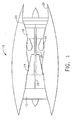
- Figure 1 is a schematic illustration of a gas turbine engine 10 including a low pressure compressor 12, a high pressure compressor 14, and a combustor 16.
- Engine 10 also includes a high pressure turbine 18 and a low pressure turbine 20.
- Compressor 12 and turbine 20 are coupled by a first shaft 24, and compressor 14 and turbine 18 are coupled by a second shaft 26.
- the gas turbine engine is a GE90 available from General Electric Company, Cincinnati, Ohio.
- the highly compressed air is delivered to combustor 16.
- Airflow from combustor 16 drives turbines 18 and 20 before exiting gas turbine engine 10.
- Figure 2 is an enlarged partial cross-sectional view of a portion of gas turbine engine 10. Specifically, Figure 2 illustrates an enlarged partial cross-sectional view of high pressure turbine 18.
- High pressure turbine 18 includes first and second stage disks 30 and 32, respectively. Each stage disk 30 and 32 includes a respective web portion 34 that extends radially outward from a bore (not shown) to a respective blade dovetail slot 38 and 40.
- An interstage seal assembly 50 extends axially between turbine stage disks 30 and 32. More specifically, seal assembly 50 includes an interstage seal member 52 and a disk or blade retainer 53. Interstage seal member 52 includes an outer shell 54 and a central disk 56 which has a web portion 58 and a bore (not shown). Shell 54 is generally cylindrical and includes an upstream or forward arm 60 and a downstream or aft arm 62.
- Each arm 60 and 62 is arcuate and extends in an axial direction with an inwardly convex shape. More specifically, each arm 60 and 62 extends with a catenary curve from a mid portion 80 of outer shell 54 to each respective disk 30 and 32. Mid portion 80 includes a plurality of seal teeth 82 which contact a seal member 84 coupled to a radially inner side 86 of a second stage nozzle assembly 88.
- a flange 90 and 92 is formed integrally at an upstream and downstream end 94 and 96, respectively, of each arm 60 and 62.
- Flanges 90 and 92 enable interstage seal member 52 to couple between first and second stage disks 30 and 32, respectively. More specifically, aft flange 92 enables interstage seal arm 62 to couple to second stage disk 32 with an interference fit, rather than with the use of any fasteners.
- forward flange 90 enables interstage seal arm 60 to couple to first stage disk 30 with an interference fit, rather than with the use of any fasteners.
- Disk retainer 53 extends along a downstream side 100 of first stage disk dovetail slot 38 to facilitate retaining first stage rotor blades 102 within dovetail slot 38. More specifically, retainer 53 has a radially outer end 110, a radially inner end 112, and a body 114 extending therebetween. Radially inner end 112 extends generally perpendicularly upstream from body 114 such that an elbow 116 is formed between body 114 and end 112. Elbow 116 facilitates maintaining disk retainer 53 in a proper position relative to first stage disk 30, and also facilitates coupling disk retainer 53 to interstage seal member 52 in a boltless connection.
- Disk retainer 53 is coupled to first stage disk 30 with a radial interference fit. Specifically, disk retainer 53 is retained in position relative to first stage disk 30 and to interstage seal assembly 50 by interstage seal member 60, such that disk retainer elbow 116 is received within interstage seal arm flange 90. More specifically, as interstage seal assembly 50 is coupled to disk retainer 53, as described below, interstage seal assembly 50 orients disk retainer 53 such that retainer 53 is substantially centered with respect to first stage disk 30. Moreover, the radial interference fit between disk retainer 53 and interstage seal member 52 facilitates centering seal member 52 with respect to turbine 18.
- blade retainer 53 is inserted in position within rotor assembly 18 such that blade retainer 53 engages first stage disk 30.
- Interstage seal member 52 is then axially squeezed or compressed and coupled within rotor assembly 18 such that interstage seal member arm 60 is coupled against blade retainer 53 in a radial interference fit, and such that seal member arm 62 is coupled against second stage disk 32 in an interference fit.
- seal member 52 when assembled, because seal member 52 is in compression, seal member 52, and more specifically, the catenary curvature of arms 60 and 62, causes an axial load to be induced to blade retainer 53.
- the axial loading facilitates maintaining blade retainer 53 in position relative to first stage disk 30 and interstage seal assembly 50.
- the radial interference fit between blade retainer 53 and first stage disk 30, and the radial interference fit between blade retainer 53 and interstage seal member 52 facilitate centering blade retainer 53 with respect to first stage disk 30 and with respect to interstage seal assembly 50.
- the above-described interstage seal assemblies are cost-effective and highly reliable.
- the interstage seal assembly includes an interstage seal member and a separate disk retainer.
- the disk retainer is maintained in an interference fit with the first stage disk by the interstage seal member.
- the interstage seal member is coupled to both the disk retainer and the rotor assembly by interference fits. Accordingly, assembly times are facilitated to be reduced, as no fasteners are needed to couple the interstage seal assembly within the rotor assembly.
- the interference fit between the interstage seal member and the disk retainer facilitates increasing the low cycle fatigue life of the interstage seal assembly, while enabling the differential torque generated between the turbine stage disks to be frictionally transferred through the interstage seal assembly.
- the interstage seal assembly facilitates extending a useful life of the turbine rotor assembly in a cost-effective and reliable manner.
- each interstage seal assembly component can also be used in combination with other interstage seal assembly components and with other rotor assemblies.
Description
- This invention relates generally to gas turbine engines, and more specifically to seal assemblies used with gas turbine engine rotor assemblies.
- At least some known gas turbine engines include a core engine having, in serial flow arrangement, a fan assembly and a high pressure compressor which compress airflow entering the engine, a combustor ignites a fuel-air mixture which is then channeled towards low and high pressure turbines which each include a plurality of rotor blades that extract rotational energy from airflow exiting the combustor. The high pressure compressor is coupled by a shaft to the high pressure turbine.
- At least some known high pressure turbines include a first stage disk and a second stage disk that is coupled to the first stage disk by a bolted connection. More specifically, the rotor shaft extends between a last stage of the multi-staged compressor and the web portions of the turbine first stage disk. The first and second stage turbine disks are isolated by a forward faceplate that is coupled to a forward face of the first stage disk, and an aft seal that is coupled to a rearward face of the second stage disk web. An interstage seal assembly extends between the first and second stage disks to facilitate sealing flow around a second stage turbine nozzle.
- At least some known interstage seal assemblies include an interstage seal and a separate blade retainer. The interstage seal is coupled to the first and second stage disks with a plurality of bolts. The blade retainer includes a split ring that is coupled to an axisymmetric hook assembly extending from the turbine stage disk. However, because the seal assemblies are complex, such interstage seal assemblies may be difficult to assemble. To facilitate reducing the assembly time and costs of such seal assemblies, other known interstage seal assemblies include an integrally-formed interstage seal and blade retainer. More specifically, such seal assemblies use radial and axial interference to transmit torque from the stage two disk to the stage one disk. However, because such seal assemblies are coupled between the turbine stage disks with radial and axial interference fits, such seal assemblies may be susceptible to low cycle fatigue (LCF) stresses induced from one or both turbine stage disks.
- Prior art seal assemblies are disclosed in documents
US 4582467 andUS 6267553 . - In one aspect of the invention, a seal assembly according to claim 1 for a gas turbine engine including a first stage disk and a second stage disk is provided.
- In a further aspect, a gas turbine engine according to claim 6 comprises a rotor assembly comprising a first stage disk, a second stage disk, and a seal assembly extending therebetween. The seal assembly comprises a disk retainer and an interstage seal assembly. The interstage seal assembly comprises a radially outer shell and a web portion. The outer shell extends radially outward from the web portion and comprises an upstream arm and a downstream arm. The disk retainer is coupled between the outer shell upstream arm and the first stage disk. The downstream arm is coupled to the second stage disk.
- Embodiments of the invention will now be described, by way of example, with reference to the accompanying drawings, in which:
-
Figure 1 is a schematic illustration of a gas turbine engine; and -
Figure 2 is an enlarged partial cross-sectional view of a portion of the gas turbine engine shown inFigure 1 . -
Figure 1 is a schematic illustration of agas turbine engine 10 including alow pressure compressor 12, ahigh pressure compressor 14, and acombustor 16.Engine 10 also includes ahigh pressure turbine 18 and alow pressure turbine 20.Compressor 12 andturbine 20 are coupled by afirst shaft 24, andcompressor 14 andturbine 18 are coupled by asecond shaft 26. In one embodiment, the gas turbine engine is a GE90 available from General Electric Company, Cincinnati, Ohio. - In operation, air flows through
low pressure compressor 12 and compressed air is supplied fromlow pressure compressor 12 tohigh pressure compressor 14. The highly compressed air is delivered tocombustor 16. Airflow fromcombustor 16 drivesturbines gas turbine engine 10. -
Figure 2 is an enlarged partial cross-sectional view of a portion ofgas turbine engine 10. Specifically,Figure 2 illustrates an enlarged partial cross-sectional view ofhigh pressure turbine 18.High pressure turbine 18 includes first andsecond stage disks stage disk respective web portion 34 that extends radially outward from a bore (not shown) to a respectiveblade dovetail slot - An
interstage seal assembly 50 extends axially betweenturbine stage disks seal assembly 50 includes aninterstage seal member 52 and a disk orblade retainer 53.Interstage seal member 52 includes anouter shell 54 and acentral disk 56 which has aweb portion 58 and a bore (not shown). Shell 54 is generally cylindrical and includes an upstream orforward arm 60 and a downstream oraft arm 62. - Each
arm arm mid portion 80 ofouter shell 54 to eachrespective disk Mid portion 80 includes a plurality ofseal teeth 82 which contact aseal member 84 coupled to a radiallyinner side 86 of a secondstage nozzle assembly 88. - A
flange downstream end 94 and 96, respectively, of eacharm Flanges interstage seal member 52 to couple between first andsecond stage disks aft flange 92 enablesinterstage seal arm 62 to couple tosecond stage disk 32 with an interference fit, rather than with the use of any fasteners. In addition, as described in more detail below,forward flange 90 enablesinterstage seal arm 60 to couple tofirst stage disk 30 with an interference fit, rather than with the use of any fasteners. -
Disk retainer 53 extends along adownstream side 100 of first stagedisk dovetail slot 38 to facilitate retaining firststage rotor blades 102 withindovetail slot 38. More specifically,retainer 53 has a radiallyouter end 110, a radiallyinner end 112, and abody 114 extending therebetween. Radiallyinner end 112 extends generally perpendicularly upstream frombody 114 such that anelbow 116 is formed betweenbody 114 andend 112. Elbow 116 facilitates maintainingdisk retainer 53 in a proper position relative tofirst stage disk 30, and also facilitatescoupling disk retainer 53 to interstageseal member 52 in a boltless connection. -
Disk retainer 53 is coupled tofirst stage disk 30 with a radial interference fit. Specifically,disk retainer 53 is retained in position relative tofirst stage disk 30 and to interstageseal assembly 50 byinterstage seal member 60, such thatdisk retainer elbow 116 is received within interstageseal arm flange 90. More specifically, asinterstage seal assembly 50 is coupled todisk retainer 53, as described below,interstage seal assembly 50orients disk retainer 53 such thatretainer 53 is substantially centered with respect tofirst stage disk 30. Moreover, the radial interference fit betweendisk retainer 53 andinterstage seal member 52 facilitates centeringseal member 52 with respect toturbine 18. - During assembly, initially
blade retainer 53 is inserted in position withinrotor assembly 18 such thatblade retainer 53 engagesfirst stage disk 30.Interstage seal member 52 is then axially squeezed or compressed and coupled withinrotor assembly 18 such that interstageseal member arm 60 is coupled againstblade retainer 53 in a radial interference fit, and such thatseal member arm 62 is coupled againstsecond stage disk 32 in an interference fit. Accordingly, when assembled, becauseseal member 52 is in compression,seal member 52, and more specifically, the catenary curvature ofarms blade retainer 53. The axial loading facilitates maintainingblade retainer 53 in position relative tofirst stage disk 30 andinterstage seal assembly 50. Moreover, the radial interference fit betweenblade retainer 53 andfirst stage disk 30, and the radial interference fit betweenblade retainer 53 andinterstage seal member 52 facilitatecentering blade retainer 53 with respect tofirst stage disk 30 and with respect tointerstage seal assembly 50. - The above-described interstage seal assemblies are cost-effective and highly reliable. The interstage seal assembly includes an interstage seal member and a separate disk retainer. The disk retainer is maintained in an interference fit with the first stage disk by the interstage seal member. The interstage seal member is coupled to both the disk retainer and the rotor assembly by interference fits. Accordingly, assembly times are facilitated to be reduced, as no fasteners are needed to couple the interstage seal assembly within the rotor assembly. Moreover, the interference fit between the interstage seal member and the disk retainer facilitates increasing the low cycle fatigue life of the interstage seal assembly, while enabling the differential torque generated between the turbine stage disks to be frictionally transferred through the interstage seal assembly. As a result, the interstage seal assembly facilitates extending a useful life of the turbine rotor assembly in a cost-effective and reliable manner.
- Exemplary embodiments of rotor assemblies are described above in detail. The rotor assemblies are not limited to the specific embodiments described herein, but rather, components of each assembly may be utilized independently and separately from other components described herein. For example, each interstage seal assembly component can also be used in combination with other interstage seal assembly components and with other rotor assemblies.
Claims (8)
- A seal assembly for a gas turbine engine (10) including a first stage disk (30) and a second stage disk (32), said seal assembly comprising:a disk retainer (53); andan interstage seal assembly (50) extending between the first and second stage disks when said seal assembly is coupled between the first and second stage disks, said interstage seal assembly comprising a radially outer shell (54) extending radially outward from a web portion (58), said outer shell comprising an upstream arm (60) and a downstream arm (62) extending outwardly from said outer shell, wherein, when said seal assembly is coupled between the first and second stage disks, said disk retainer is coupled between said outer shell upstream arm and the first stage disk and said downstream arm is coupled to said second stage disk, characterized in that said upstream arm (60) is coupled to said disk retainer (53) with an interference fit and said downstream arm (62) is coupled to the second stage disk (32) with a interference fit when said seal assembly is coupled between the first and second stage disks.
- A seal assembly in accordance with Claim 1 wherein when said seal assembly is coupled between the first and second stage disks said disk retainer (53) is secured in position by axial loading induced from said interstage seal assembly (50).
- A seal assembly in accordance with Claim 1 wherein said upstream and downstream arms (60 and 62) each extend arcuately in a catenary contour from said outer shell (54).
- A seal assembly in accordance with Claim 3 wherein said outer shell (54) is in compression when said seal assembly (50) is coupled between the first and second stage disks (30 and 32).
- A seal assembly in accordance with Claim 1 wherein said seal assembly (50) facilitates extending a useful life of the turbine engine.
- A gas turbine engine (10) comprising a rotor assembly (18) comprising a first stage disk (30), a second stage disk (32), and a seal assembly as claimed in claim 1.
- A gas turbine engine (10) in accordance with Claim 6 wherein said seal assembly disk retainer (53) is secured in position by axial loading induced from said interstage seal (50).
- A gas turbine engine (10) in accordance with Claim 6 wherein at least one of said interstage seal assembly upstream and downstream arms (60 and 62) extends arcuately in a catenary contour from said outer shell (54).
Applications Claiming Priority (2)
| Application Number | Priority Date | Filing Date | Title |
|---|---|---|---|
| US653337 | 2003-09-02 | ||
| US10/653,337 US6899520B2 (en) | 2003-09-02 | 2003-09-02 | Methods and apparatus to reduce seal rubbing within gas turbine engines |
Publications (3)
| Publication Number | Publication Date |
|---|---|
| EP1512841A2 EP1512841A2 (en) | 2005-03-09 |
| EP1512841A3 EP1512841A3 (en) | 2012-07-25 |
| EP1512841B1 true EP1512841B1 (en) | 2014-03-19 |
Family
ID=34136647
Family Applications (1)
| Application Number | Title | Priority Date | Filing Date |
|---|---|---|---|
| EP04255281.0A Expired - Fee Related EP1512841B1 (en) | 2003-09-02 | 2004-09-01 | Seal assembly for gas turbine engine |
Country Status (4)
| Country | Link |
|---|---|
| US (1) | US6899520B2 (en) |
| EP (1) | EP1512841B1 (en) |
| JP (1) | JP2005098297A (en) |
| CN (1) | CN100404818C (en) |
Families Citing this family (26)
| Publication number | Priority date | Publication date | Assignee | Title |
|---|---|---|---|---|
| US7334983B2 (en) | 2005-10-27 | 2008-02-26 | United Technologies Corporation | Integrated bladed fluid seal |
| US7722314B2 (en) * | 2006-06-22 | 2010-05-25 | General Electric Company | Methods and systems for assembling a turbine |
| US8167547B2 (en) * | 2007-03-05 | 2012-05-01 | United Technologies Corporation | Gas turbine engine with canted pocket and canted knife edge seal |
| US8388310B1 (en) | 2008-01-30 | 2013-03-05 | Siemens Energy, Inc. | Turbine disc sealing assembly |
| US8038399B1 (en) * | 2008-11-22 | 2011-10-18 | Florida Turbine Technologies, Inc. | Turbine rim cavity sealing |
| US8235656B2 (en) * | 2009-02-13 | 2012-08-07 | General Electric Company | Catenary turbine seal systems |
| US8177495B2 (en) * | 2009-03-24 | 2012-05-15 | General Electric Company | Method and apparatus for turbine interstage seal ring |
| US8348603B2 (en) * | 2009-04-02 | 2013-01-08 | General Electric Company | Gas turbine inner flowpath coverpiece |
| US8511976B2 (en) | 2010-08-02 | 2013-08-20 | General Electric Company | Turbine seal system |
| US8608436B2 (en) | 2010-08-31 | 2013-12-17 | General Electric Company | Tapered collet connection of rotor components |
| US8740554B2 (en) | 2011-01-11 | 2014-06-03 | United Technologies Corporation | Cover plate with interstage seal for a gas turbine engine |
| US8662845B2 (en) | 2011-01-11 | 2014-03-04 | United Technologies Corporation | Multi-function heat shield for a gas turbine engine |
| US8840375B2 (en) | 2011-03-21 | 2014-09-23 | United Technologies Corporation | Component lock for a gas turbine engine |
| US8550784B2 (en) * | 2011-05-04 | 2013-10-08 | United Technologies Corporation | Gas turbine engine rotor construction |
| US20130082446A1 (en) * | 2011-09-30 | 2013-04-04 | General Electric Company | Method of repairing rotating machine components |
| US9080456B2 (en) | 2012-01-20 | 2015-07-14 | General Electric Company | Near flow path seal with axially flexible arms |
| US9540940B2 (en) | 2012-03-12 | 2017-01-10 | General Electric Company | Turbine interstage seal system |
| US9470104B2 (en) * | 2013-01-31 | 2016-10-18 | Hamilton Sundstrand Corporation | Air cycle machine with seal shaft |
| FR3011031B1 (en) * | 2013-09-25 | 2017-12-29 | Herakles | ROTARY ASSEMBLY FOR TURBOMACHINE |
| US10337345B2 (en) | 2015-02-20 | 2019-07-02 | General Electric Company | Bucket mounted multi-stage turbine interstage seal and method of assembly |
| US10502080B2 (en) | 2015-04-10 | 2019-12-10 | United Technologies Corporation | Rotating labyrinth M-seal |
| US10774668B2 (en) * | 2017-09-20 | 2020-09-15 | General Electric Company | Intersage seal assembly for counter rotating turbine |
| EP3540180A1 (en) * | 2018-03-14 | 2019-09-18 | General Electric Company | Inter-stage cavity purge ducts |
| CN112534119B (en) * | 2018-08-02 | 2023-04-14 | 西门子能源全球有限两合公司 | Rotor with a rotor component arranged between two rotor disks |
| CN109611160B (en) * | 2018-12-26 | 2020-08-11 | 北京航空航天大学 | Fluid-tight 'horseshoe' comb tooth of rotating part |
| CN112282853B (en) * | 2020-10-29 | 2022-06-03 | 中国航发湖南动力机械研究所 | Two-stage turbine and engine |
Family Cites Families (22)
| Publication number | Priority date | Publication date | Assignee | Title |
|---|---|---|---|---|
| US3842595A (en) * | 1972-12-26 | 1974-10-22 | Gen Electric | Modular gas turbine engine |
| US4088422A (en) | 1976-10-01 | 1978-05-09 | General Electric Company | Flexible interstage turbine spacer |
| US4582467A (en) * | 1983-12-22 | 1986-04-15 | United Technologies Corporation | Two stage rotor assembly with improved coolant flow |
| US4659289A (en) * | 1984-07-23 | 1987-04-21 | United Technologies Corporation | Turbine side plate assembly |
| US4664599A (en) * | 1985-05-01 | 1987-05-12 | United Technologies Corporation | Two stage turbine rotor assembly |
| US5197281A (en) | 1990-04-03 | 1993-03-30 | General Electric Company | Interstage seal arrangement for airfoil stages of turbine engine counterrotating rotors |
| US5131814A (en) | 1990-04-03 | 1992-07-21 | General Electric Company | Turbine blade inner end attachment structure |
| US5236302A (en) | 1991-10-30 | 1993-08-17 | General Electric Company | Turbine disk interstage seal system |
| US5288210A (en) | 1991-10-30 | 1994-02-22 | General Electric Company | Turbine disk attachment system |
| US5275534A (en) | 1991-10-30 | 1994-01-04 | General Electric Company | Turbine disk forward seal assembly |
| US5226785A (en) * | 1991-10-30 | 1993-07-13 | General Electric Company | Impeller system for a gas turbine engine |
| EP0626036B1 (en) * | 1992-02-10 | 1996-10-09 | United Technologies Corporation | Improved cooling fluid ejector |
| US5217348A (en) * | 1992-09-24 | 1993-06-08 | United Technologies Corporation | Turbine vane assembly with integrally cast cooling fluid nozzle |
| US5338154A (en) * | 1993-03-17 | 1994-08-16 | General Electric Company | Turbine disk interstage seal axial retaining ring |
| US5318405A (en) | 1993-03-17 | 1994-06-07 | General Electric Company | Turbine disk interstage seal anti-rotation key through disk dovetail slot |
| US5749701A (en) | 1996-10-28 | 1998-05-12 | General Electric Company | Interstage seal assembly for a turbine |
| US6139264A (en) | 1998-12-07 | 2000-10-31 | General Electric Company | Compressor interstage seal |
| US6267553B1 (en) * | 1999-06-01 | 2001-07-31 | Joseph C. Burge | Gas turbine compressor spool with structural and thermal upgrades |
| US6283712B1 (en) * | 1999-09-07 | 2001-09-04 | General Electric Company | Cooling air supply through bolted flange assembly |
| US6398488B1 (en) | 2000-09-13 | 2002-06-04 | General Electric Company | Interstage seal cooling |
| US6464453B2 (en) | 2000-12-04 | 2002-10-15 | General Electric Company | Turbine interstage sealing ring |
| FR2825748B1 (en) * | 2001-06-07 | 2003-11-07 | Snecma Moteurs | TURBOMACHINE ROTOR ARRANGEMENT WITH TWO BLADE DISCS SEPARATED BY A SPACER |
-
2003
- 2003-09-02 US US10/653,337 patent/US6899520B2/en not_active Expired - Lifetime
-
2004
- 2004-09-01 EP EP04255281.0A patent/EP1512841B1/en not_active Expired - Fee Related
- 2004-09-01 JP JP2004253719A patent/JP2005098297A/en active Pending
- 2004-09-02 CN CNB2004100751505A patent/CN100404818C/en active Active
Also Published As
| Publication number | Publication date |
|---|---|
| US6899520B2 (en) | 2005-05-31 |
| EP1512841A3 (en) | 2012-07-25 |
| US20050047910A1 (en) | 2005-03-03 |
| JP2005098297A (en) | 2005-04-14 |
| EP1512841A2 (en) | 2005-03-09 |
| CN100404818C (en) | 2008-07-23 |
| CN1611754A (en) | 2005-05-04 |
Similar Documents
| Publication | Publication Date | Title |
|---|---|---|
| EP1512841B1 (en) | Seal assembly for gas turbine engine | |
| CA2503930C (en) | Gas turbine engine variable vane assembly | |
| US7344354B2 (en) | Methods and apparatus for operating gas turbine engines | |
| JP2017025915A (en) | Method and system for interfacing ceramic matrix composite component with metallic component | |
| US7661260B2 (en) | Gas turbine engine assembly and method of assembling same | |
| EP2971693B1 (en) | Gas turbine engine rotor disk-seal arrangement | |
| EP1693552A2 (en) | A turbine blade | |
| US6951112B2 (en) | Methods and apparatus for assembling gas turbine engines | |
| US7229252B2 (en) | Rotor assembly retaining apparatus | |
| US20100166562A1 (en) | Turbine blade root configurations | |
| CN111379592A (en) | Hybrid rotor blade for a turbine engine | |
| EP4001596B1 (en) | Gas turbine engine | |
| EP3091189A1 (en) | Airfoil assembly for a stator of a gas turbine engine compressor | |
| EP1087101B1 (en) | Coupling assembly and method for connecting air ducts in gas turbine rotors | |
| US20150118055A1 (en) | Gas turbine engine rotor assembly and method of assembling the same | |
| EP3819463B1 (en) | Turbine assembly with ceramic matrix composite components and interstage sealing features | |
| EP3460196B1 (en) | Bearing assembly for a variable stator vane | |
| US20230167745A1 (en) | Gas turbine engine including a rotating blade assembly | |
| US11686202B1 (en) | Rotor damper with contact biasing feature for turbine engines | |
| US20050172638A1 (en) | Methods and apparatus for assembling gas turbine engines | |
| CN114109615A (en) | Air turbine starter with nozzle retention mechanism | |
| GB2415017A (en) | Heat shield for attachment to a casing of a gas turbine engine |
Legal Events
| Date | Code | Title | Description |
|---|---|---|---|
| PUAI | Public reference made under article 153(3) epc to a published international application that has entered the european phase |
Free format text: ORIGINAL CODE: 0009012 |
|
| AK | Designated contracting states |
Kind code of ref document: A2 Designated state(s): AT BE BG CH CY CZ DE DK EE ES FI FR GB GR HU IE IT LI LU MC NL PL PT RO SE SI SK TR |
|
| AX | Request for extension of the european patent |
Extension state: AL HR LT LV MK |
|
| RIN1 | Information on inventor provided before grant (corrected) |
Inventor name: HABEDANK, MARK STEVEN Inventor name: DZIECH, MICHAEL AARON Inventor name: LEAGUE, CHRISTOPHER JAMES Inventor name: WINES, DANIEL EDWARD Inventor name: WHITAKER, GEORGE EDWIN |
|
| PUAL | Search report despatched |
Free format text: ORIGINAL CODE: 0009013 |
|
| AK | Designated contracting states |
Kind code of ref document: A3 Designated state(s): AT BE BG CH CY CZ DE DK EE ES FI FR GB GR HU IE IT LI LU MC NL PL PT RO SE SI SK TR |
|
| AX | Request for extension of the european patent |
Extension state: AL HR LT LV MK |
|
| RIC1 | Information provided on ipc code assigned before grant |
Ipc: F01D 11/02 20060101AFI20120618BHEP Ipc: F01D 11/00 20060101ALN20120618BHEP Ipc: F01D 5/06 20060101ALN20120618BHEP |
|
| 17P | Request for examination filed |
Effective date: 20130125 |
|
| 17Q | First examination report despatched |
Effective date: 20130222 |
|
| AKX | Designation fees paid |
Designated state(s): DE FR GB |
|
| RIC1 | Information provided on ipc code assigned before grant |
Ipc: F01D 11/00 20060101ALN20130822BHEP Ipc: F01D 5/06 20060101ALN20130822BHEP Ipc: F01D 11/02 20060101AFI20130822BHEP |
|
| RIC1 | Information provided on ipc code assigned before grant |
Ipc: F01D 11/00 20060101ALN20130904BHEP Ipc: F01D 5/06 20060101ALN20130904BHEP Ipc: F01D 11/02 20060101AFI20130904BHEP |
|
| GRAP | Despatch of communication of intention to grant a patent |
Free format text: ORIGINAL CODE: EPIDOSNIGR1 |
|
| INTG | Intention to grant announced |
Effective date: 20131011 |
|
| GRAS | Grant fee paid |
Free format text: ORIGINAL CODE: EPIDOSNIGR3 |
|
| GRAA | (expected) grant |
Free format text: ORIGINAL CODE: 0009210 |
|
| AK | Designated contracting states |
Kind code of ref document: B1 Designated state(s): DE FR GB |
|
| REG | Reference to a national code |
Ref country code: GB Ref legal event code: FG4D |
|
| REG | Reference to a national code |
Ref country code: DE Ref legal event code: R096 Ref document number: 602004044626 Country of ref document: DE Effective date: 20140424 |
|
| REG | Reference to a national code |
Ref country code: DE Ref legal event code: R097 Ref document number: 602004044626 Country of ref document: DE |
|
| PLBE | No opposition filed within time limit |
Free format text: ORIGINAL CODE: 0009261 |
|
| STAA | Information on the status of an ep patent application or granted ep patent |
Free format text: STATUS: NO OPPOSITION FILED WITHIN TIME LIMIT |
|
| 26N | No opposition filed |
Effective date: 20141222 |
|
| REG | Reference to a national code |
Ref country code: DE Ref legal event code: R097 Ref document number: 602004044626 Country of ref document: DE Effective date: 20141222 |
|
| REG | Reference to a national code |
Ref country code: FR Ref legal event code: PLFP Year of fee payment: 13 |
|
| PGFP | Annual fee paid to national office [announced via postgrant information from national office to epo] |
Ref country code: GB Payment date: 20160927 Year of fee payment: 13 |
|
| PGFP | Annual fee paid to national office [announced via postgrant information from national office to epo] |
Ref country code: FR Payment date: 20160926 Year of fee payment: 13 |
|
| PGFP | Annual fee paid to national office [announced via postgrant information from national office to epo] |
Ref country code: DE Payment date: 20160928 Year of fee payment: 13 |
|
| REG | Reference to a national code |
Ref country code: DE Ref legal event code: R119 Ref document number: 602004044626 Country of ref document: DE |
|
| GBPC | Gb: european patent ceased through non-payment of renewal fee |
Effective date: 20170901 |
|
| REG | Reference to a national code |
Ref country code: FR Ref legal event code: ST Effective date: 20180531 |
|
| PG25 | Lapsed in a contracting state [announced via postgrant information from national office to epo] |
Ref country code: DE Free format text: LAPSE BECAUSE OF NON-PAYMENT OF DUE FEES Effective date: 20180404 Ref country code: GB Free format text: LAPSE BECAUSE OF NON-PAYMENT OF DUE FEES Effective date: 20170901 |
|
| PG25 | Lapsed in a contracting state [announced via postgrant information from national office to epo] |
Ref country code: FR Free format text: LAPSE BECAUSE OF NON-PAYMENT OF DUE FEES Effective date: 20171002 |