EP1511339A1 - Mobile communication system using downlink shared channel - Google Patents
Mobile communication system using downlink shared channel Download PDFInfo
- Publication number
- EP1511339A1 EP1511339A1 EP02728205A EP02728205A EP1511339A1 EP 1511339 A1 EP1511339 A1 EP 1511339A1 EP 02728205 A EP02728205 A EP 02728205A EP 02728205 A EP02728205 A EP 02728205A EP 1511339 A1 EP1511339 A1 EP 1511339A1
- Authority
- EP
- European Patent Office
- Prior art keywords
- data
- mobile
- channel
- downlink shared
- shared channel
- Prior art date
- Legal status (The legal status is an assumption and is not a legal conclusion. Google has not performed a legal analysis and makes no representation as to the accuracy of the status listed.)
- Withdrawn
Links
Images





Classifications
-
- H—ELECTRICITY
- H04—ELECTRIC COMMUNICATION TECHNIQUE
- H04W—WIRELESS COMMUNICATION NETWORKS
- H04W72/00—Local resource management
- H04W72/20—Control channels or signalling for resource management
- H04W72/23—Control channels or signalling for resource management in the downlink direction of a wireless link, i.e. towards a terminal
-
- H—ELECTRICITY
- H04—ELECTRIC COMMUNICATION TECHNIQUE
- H04W—WIRELESS COMMUNICATION NETWORKS
- H04W4/00—Services specially adapted for wireless communication networks; Facilities therefor
- H04W4/06—Selective distribution of broadcast services, e.g. multimedia broadcast multicast service [MBMS]; Services to user groups; One-way selective calling services
-
- H—ELECTRICITY
- H04—ELECTRIC COMMUNICATION TECHNIQUE
- H04W—WIRELESS COMMUNICATION NETWORKS
- H04W72/00—Local resource management
- H04W72/12—Wireless traffic scheduling
- H04W72/1263—Mapping of traffic onto schedule, e.g. scheduled allocation or multiplexing of flows
- H04W72/1268—Mapping of traffic onto schedule, e.g. scheduled allocation or multiplexing of flows of uplink data flows
-
- H—ELECTRICITY
- H04—ELECTRIC COMMUNICATION TECHNIQUE
- H04W—WIRELESS COMMUNICATION NETWORKS
- H04W72/00—Local resource management
- H04W72/30—Resource management for broadcast services
Definitions
- the present invention relates to a communication method and device in a mobile communication system using a downlink shared channel (DSCH).
- DSCH downlink shared channel
- CDMA Code Division Multiple Access
- W-CDMA Wideband-CDMA
- Communication systems adapted to these demands are generally called third generation mobile communication systems and the standards relating thereto are co-coordinated by the 3GPP (Third Generation Partnership Project), which is the world standardization organization; introduction of such systems has already begun.
- 3GPP Third Generation Partnership Project
- a DSCH downlink shared channel
- a DSCH downlink shared channel
- 3GPP TS 25.427, TS 25.435 3GPP TS 25.427, TS 25.435.
- DSCH a single channel can be shared by a large number of mobiles and flexible power control can be achieved. In this way, high-speed and high-efficiency data communication can be implemented with limited wireless resources so the importance of this technique is expected to increase in the future.
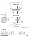
- FIG. 1A to 1C show an outline of downlink data communication (communication to mobiles) in a communication system employing DSCH.
- This system comprises a core network 100, which is a wired network, a wireless network control device 101, base stations 102 and mobiles 103.
- DSCH is the name given to the channel between the wireless network control device 101 and the base stations 102; this DSCH is mapped onto a PDSCH (physical downlink shared channel), which is one of the physical channels on wireless.
- PDSCH physical downlink shared channel
- DCH dedicated channel
- DPCH dedicated physical channel
- the mobile 103 is not always in receiving condition in regard to the PDSCH but only receives data on the PDSCH if signaling data has been received on the DPCH.
- the ability to receive data on the DSCH therefore only exists in the case where a dedicated CH is set up in respect of the mobile 103; data cannot be received on the DSCH in the idle state or in a condition in which a dedicated channel is not set up. It should be noted that the mobile 103 is normally able to receive signaling data on the DPCH.
- Mapping of the aforesaid signaling data wirelessly onto DPCH is as described above. Two methods are laid down between the wireless network control device 101 and base station 102. In one case, data is transmitted on DCH. In the other case, data is transmitted on another channel established for the signaling.
- the DSCH data must be transmitted later than the signaling by a delay time ⁇ T.
- the DSCH data is transmitted in accordance with a standard timing that is set for each sector, so the reception timings thereof are the same for the mobiles 103. In contrast, the DPCH reception timings are different for each of the mobiles 103. Consequently, the aforesaid delay time ⁇ T also differs for each mobile 103.
- the wireless network control device 101 must therefore perform transmission timing control of the signaling data, in consideration the delay time ⁇ T for each mobile 103.
- the delay time ⁇ T is respectively reported to the wireless network control device 101, base station 102 and mobile 103 by the application at the time point of call set-up.
- the identifier ID 104-2 that is applied to each mobile is stored in the DSCH frame 104 in addition to the user data 104-1. This is necessary in order that the DSCH frame 104 should be correctly transmitted to a specified mobile 103.
- transmission can only be effected in respect of a single mobile 103 in a single transmission slot; a DSCH frame that is transmitted in this transmission slot cannot be simultaneously received by a plurality of mobiles 103.
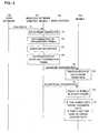
- FIG. 2 shows an example of the processing sequence in DSCH transmission.
- the wireless network control device 101 receives (step S1) user data 104-1 from the core network 100, it generates a DSCH frame 104 (processing step P1) from the information that was already set as the user data 104-1. After this, the transmission timing of the DSCH frame 104 is determined (processing step P2).
- the transmission timing of the signaling data is determined (processing step P4) using the aforesaid delay time ⁇ T, from the DSCH frame transmission timing.
- the signaling data is transmitted (step S2) to the mobile 103 through the base station 102 in accordance with the signaling transmission timing.
- a mobile 103 When a mobile 103 receives signaling data, it becomes aware of the existence of a DSCH frame that is to be received on the PDSCH, and starts preparation to receive this DSCH frame (processing step P5). After this, the wireless network control device 101 transmits the DSCH frame to the mobile 103 (step S3) through the base station 102 in accordance with the DSCH frame transmission timing.
- the mobile 103 After receiving this DSCH frame, the mobile 103 compares the mobile identifier ID 104-2 in the data with its own ID (processing step P6) and, if theyagree, performs subsequent data processing. Also, if the mobile ID 104-2 in the DSCH frame data does not agree with its own ID, it discards this DSCH frame (processing step P7).
- An object of the present invention is therefore to provide an efficient communication method and device based on the current DSCH technique, whereby diverse services, in particular distribution system services (multi-cast services) can be implemented in future by improving the communication rate.
- an object of the present invention is to provide a communication method and device aimed at implementing further new services wherein for example data distribution is performed on DSCH only during telephone service.
- a characteristic feature of a communication method and device according to the present invention capable of meeting this object and comprising a wireless network control device, base stations and mobiles on which there is respectively installed one or more communication protocol as specified by for example 3GPP is the performance of multi-cast communication of data in respect of one or more mobiles using DSCH.
- said wireless network control device is characterized by the provision of a functional section that processes DSCH internally and, in addition, the provision of table means that stores various types of setting information relating to DSCH communication and DSCH multi-cast communication. Using these items of information, multi-cast communication (including unicast communication) is implemented using DSCH in respect of one or more mobiles .
- a base station in accordance with the present invention comprises a function of transmitting DSCH data and/or said signaling data received from the wireless network control device to the mobiles through a wireless circuit.
- a mobile may comprise an identification function in respect of whether data on the DSCH is unicast or multicast.
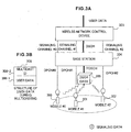
- Figure 3 is a view given in explanation of an outline of a multicast DSCH communication method according to the present invention.
- Figure 4 is an operating sequence diagram of the multicast DSCH communication method according to Figure 3.
- the reason why data can only be received by a single mobile for a single transmission slot is that a mobile ID is present in the DSCH frame.
- identification information (multicast ID) for multicast is stored in the mobile ID storage area 306-2 of the DSCH frame 306 comprising the user data storage area 306-1 and mobile identifier ID storage area 306-2.
- Figure 3A shows how a DSCH frame 306 using the aforesaid multicast ID is simultaneously received after reception of signaling data on their respective DPCHs by a plurality of mobiles 300 to 302.
- the wireless network control device 303 receives user data from the core network 100 (not shown in Figure 3) (step S11), it determines whether this user data is to be multicast or not; if this data is not to be multicast, it performs unicast processing in accordance with the sequence described in Figure 2.
- the wireless network control device 303 If the user data received from the core network 100 is to be multicast, the wireless network control device 303 generates the DSCH frame 306 of Figure 3B (processing step P11) from the information that was already set as the user data in question.
- the transmission timing of the DSCH frame 306 is determined (processing step P12).
- the multicast ID is stored in the multicast ID storage region 306-2 described in Figure 3 in the DSCH frame 306.
- the wireless network control device 303 selects mobiles 300 to 302 in respective of which multicasting is to be performed (processing step P13) and determines (processing step P14) the transmission timing of the signaling frame and the generation of the signaling data for each mobile that is the subject of this multicasting.
- the respective signaling data are transmitted (step S12) to all the mobiles 300 to 302 that are the subject of multicasting through the base stations 304, with the aforesaid signaling transmission timing.
- the mobiles receive this signaling, they recognize the presence of the DSCH frame that is to be received on PDSCH and commence preparations for reception of this DCSH frame (processing steps P14-1 to P14-3).
- the wireless network control device 303 transmits the DSCH frame through the base stations of 304 to the mobiles 300 to 302 with the DSCH frame transmission timing (step S13).
- the mobiles After the mobiles have all received the DSCH frame 306 transmitted as described above, they check the mobile identifier ID in the respectively received data (processing step P15) and, if the identifier ID agrees with the multicast ID, continue processing of this received data (processing step P16). If the ID is not a multicast ID, in the processing step P6 in the sequence of Figure 2, the mobiles compare the ID with their own IDs, respectively and, if they agree, perform the subsequent data processing. Also, if the ID in the received data and their own ID do not agree, they discard the DSCH frame 306 (processing step P7).
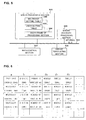
- Figure 5 shows an embodiment of a wireless network control device 303 according to the present invention.
- the wireless network control device 303 comprises' a DSCH processing section 500, macro diversity processing section 505, main control section 507 and circuit terminating section 506; the respective functional sections are connected by an internal bus 501.
- the macro diversity processing section 505 is a functional section for implementing macro diversity, which is a characteristic technique in mobile communication.
- macro diversity a plurality of channels are set up between a given node and a given mobile and identical data are copied and transmitted to all of the plurality of channels by the transmitting end. This is employed because communication quality such as during handover is improved by selecting at the receiving end the data of highest quality, of the identical data received on the plurality of channels.
- the macro diversity processing section 505 chiefly performs the following two processes.
- the circuit terminating section 506 has the function of terminating all circuits such as on the side of the core network 100 or on the side of the base stations 304 and of using the channel to transmit data to a processing block in a suitable device or another node.
- the main control section 507 has the function of exchanging control information with other nodes.
- the DSCH processing section 500 comprises a DSCH frame processing section 504 that performs therein DSCH frame generation arid transmission timing adjustment etc, a multicast setting table 502 that stores information relating to multicasting using DSCH, and a DSCH setting table 503 that stores information for ordinary DSCH communication.
- the control in formation received from the main control section 507 etc is set and stored in the multicast setting table 502 and/or the DSCH setting table 503. This information that has thus been set and stored is referenced during for example frame generation processing or transmission timing determination by the DSCH frame processing section 504.
- FIG. 6 shows a practical example of a multicast setting table 502.
- the layout of the multicast setting table 502 is that a single row shows the setting information of a single multicast group; this setting information comprises (a) a multicast channel identifier ID, (b) a DSCH identifier ID, (c) the number of mobiles participating in this multicast group and (d) the identifier IDs of these mobiles.
- Figure 7 shows a practical example of the DSCH setting table 503.
- One row of the layout of the DSCH setting table 503 indicates the setting information relating to a single DSCH; this setting information comprises: (a) the identifier ID of the dedicated channel, (b) a DSCH identifier ID, (c) the identifier IDs of the mobiles corresponding to the identifier ID of the dedicated channel, and (d) the timing offsets in the signal transmission that is set up in respect of the mobiles.
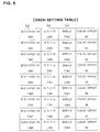
- Figure 8 and Figure 9 are views indicating what information is set in the multicast setting table 502 and the DSCH setting table 503, respectively, corresponding to the specific example of system condition shown in Figure 10.
- Figure 10 shows only the wireless network control device 304; the base stations 304 are not shown.
- three DSCHs, #0 to #2 are set up; the multicast channels MC_CH #0 and #1 and the dedicated channels CH #0 to #2 are accommodated on the DSCH #0; the multicast channel MC_CH #2 and the dedicated channels CH #3 to #6 are accommodated on the DSCH #1; and the dedicated channels CH #7 to #8 are accommodated on the DSCH #2.
- the mobiles #0 to #2 perform communication through the DSCH #0, the mobiles #0 and #2 are mobiles participating in multicasting, while the mobile #1 is a mobile that does not participate in multicasting.
- the mobiles #3 to #5 perform communication through the DSCH #1 and, of these, the mobiles #3 to #5 are mobiles participating in multicasting while the mobile #6 is a mobile that does not participate in multicasting. Further, the mobiles #7, #8 perform communication through the DSCH #2, but these mobiles do not participate in multicasting.
- the multicast setting table 502 of Figure 8 has registered therein (a) which multicast channels are (b) accommodated on which DSCH and (c) the number of multicast participant mobiles and (d) the identifier IDs of the participant mobiles.
- the DSCH setting table 503 of Figure 9 has registered therein (a) of the dedicated channel IDs, (b) the subject DSCH identifier IDs that are accommodated therein, and (c) the corresponding mobile identifier IDs.
- Figure 11 is a view showing the processing sequence from start-up of the systemup to commencement of multicast communication.
- processing step P21 When the mobile network i.e. the wireless network control device 303 and the base stations 304 are started up, various settings are performed (processing step P21) in accordance with a predetermined procedure, between these nodes. At this point, setting of the DSCHs employed in the present invention is also performed (processing step P22).
- processing step P23 setting of the data channels for multicasting between the core network 100 and the wireless network control device 303 is performed.
- the data channel for multicasting is connected for example to a data distribution server within the core network 100 (processing step P24).
- the multicasting setting table 502 within the wireless network device is updated (processing step P24) in accordance with the mapping information of the data channels for multicasting that have been set up and the DSCHs.
- step S21 communication of the multicast data from for example the data distribution server is commenced (step S21).
- the mobile 300 When the mobile 300 receives the instructions to change over to DSCH, it extracts and sets the parameters for DSCH reception that are contained in the changeover instruction signal (processing step P28).
- the methods may be considered of setting the result of this decision beforehand by the user in the mobile or of setting the result of this decision in the network.
- the wireless network control device 303 When the wireless network control device 303 receives from the mobile 300 the DSCH changeover response, if this contains a request to participate in multicasting, it updates the multicast setting table 502 therein to add the mobile in question (processing step P30).
- authentication processing may be performed in the network 100 in the event of reception of a DSCH changeover response from the mobile, if the mobile is to participate in the multicast communication, processing may be performed to add the mobile to the multicast setting table 502.
- step S24 data is distributed (step S24) from the server or the like.
- This distribution data is assembled into DSCH frames in the DSCH processing section 500 in the wireless network control device 303 and its transmission timing is determined (processing step P31) .
- signaling in respect of the addedmobile (step S25) and transmission of the DSCH frame (step 26) are performed.
- DSCH reception processing (processing step P32) is initiated.
- DSCH frame reception processing (processing step P33) is performed as described with reference to Figure 2 (processing steps P6 and P7) and Figure 4 (processing steps P15, P16).
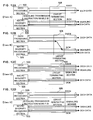
- Figure 12 shows a specific example of a method of signaling. Signaling must be transmitted to each mobile, so channels for signaling transmission must be set up allocated in units of the number of mobiles.
- the case A shown in Figure 12A is a case in which signaling is transmitted with DCH.
- the DCH is terminated by the macro diversity processing section 505, so in the event of signaling transmission the DSCH processing section 500 must output a signaling transmission instruction to the macro diversity processing section 505.
- the macro diversity processing section 505 must be able to identify in respect of which mobile (DCH) signaling is being transmitted, so the DSCH processing section 500 must give instructions for signaling transmission to the macro diversity processing section 505 and hand over the identifier ID of the mobile that is the subject of this transmission.
- the method of Figure 5 of employing an internal bus or the method of providing a dedicated control path for signal exchange may be considered.
- the macro diversity processing section 505 generates signaling data from the signaling transmission instruction and mobile identifier ID received from the DSCH processing section 500 and transmits this signaling data on the corresponding DCH. Although not shown in Figure 5, the macro diversity processing section 505 is internally provided with mapping table means of the mobile identifier ID and DCH.
- Case B shown in Figure 12B, is also a case in which signaling is transmitted with DCH. Unlike the case of Figure 12A, it has a characteristic feature-in regard to the method whereby generation and transmission of the signaling data are performed by the DSCH processing section 500 and mapping of the signaling data onto the DCH is performed by the circuit terminating section 506.
- the DSCH processing section 500 performs transmission of signaling data to the circuit terminating section 506 using the same channel ID as the channel of the DCH where the macro diversity processing section 505 terminates.
- the channel ID whereby signaling transmission was performed by the DSCH processing section 500 is the same as the ID of the DCH corresponding to the mobile that is to receive the signaling, so the signaling data is merged with the DCH in the circuit terminating section 506 before being transmitted to the corresponding mobile through the base station 304.
- the DSCH processing section 500 must simultaneously identify the channel ID of the DCH corresponding to the mobile that is registered. This can be achieved by storing as additional information in the DSCH setting table 503 shown in Figure 7.
- a channel for signaling (signaling bearer) is newly set up between the DSCH processing section 500 and base station 304. This is an example in which signaling data is transmitted using this channel.
- the signaling data that is generated in the DSCH processing section 500 is transmitted by the signaling bearer at which the DSCH processing section 500 terminates, without modification.
- a channel for signaling (signaling bearer) is newly set up between the macro diversity processing section 505 and the base station 304; this is an example of the case where signaling data is transmitted using this channel. This case also is the same as case A.
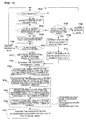
- Figure 13 is a view showing the processing flow during DSCH transmission in the wireless network control device 303, in particular in the DSCH processing section 500 and the macro diversity processing section 505.
- case A of Figure 12A is employed as the signaling method.
- the DSCH processing section 500 receives data from the core network 100 (processing step P40, Yes)
- the channel ID of the received data is extracted (processing step P41) .
- the DSCH processing section 500 checks for the existence of the channel ID extracted in the processing step P41 in the multicast setting table 502 (processing step P42) by referencing this multicast setting table 502.
- the DSCH processing section 500 extracts the DSCH-ID and all of the mobile IDs belonging to the DSCH from the multicast setting table 502 (processing step P44).
- processing step P45, No if not even one mobile ID is present in the multicast setting table 502 (processing step P45, No), nor in the DSCH setting table 503 (processing step P43, No), the data is discarded (processing step P46).
- the DSCH processing section 500 applies the data received in processing step P1 to the multicast ID to generate the DSCH frame (processing step P47).
- processing step P42 determines whether the channel ID extracted in processing step P41 is present in the multicast setting table 502 (processing step P42, No).
- the DSCH processing section 500 checks to ascertain whether or not the extracted channel ID is present in the DSCH setting table 503 (processing step P48).
- the DSCH processing section 500 discards the data received in the processing step P40 (processing step P49).
- the DSCH processing section 500 extracts the DSCH-ID and mobile ID from the DSCH setting table 503 (processing step P50). After this, the extracted mobile ID is applied to the data received in the processing step P1 and the DSCH frame is generated (processing step P51).
- the DSCH processing section 500 determines the transmission timing of the DSCH frame that has been generated (processing step P52) and acquires the timing offset of the mobile corresponding to this DSCH from the DSCH setting table 503 (processing step P53) .
- the signaling data transmission timing is calculated (processing step P54) from the DSCH frame transmission timing and the timing offset of the mobile.
- the DSCH processing section 500 reports the mobile ID and the signaling transmission instruction to the macro diversity processing section 505 (processing step P55) in accordance with the signaling timing determined in processing step P54.
- the macro diversity processing section 505 generates a signaling frame using the mobile ID and the signaling transmission instruction that are handed over from the DSCH processing section 500, and transmits this signaling frame on the corresponding DCH (processing step P56).
- the processing of the aforesaid steps P52 to P56 is executed a number of times equal to the number of mobiles.
- the DSCH processing section 500 transmits (processing step P57) the DSCH frame generated in the processing step P47 or in the processing step P51 on the DSCH in accordance with the DSCH frame transmission timing that was determined in the processing step P52.
- Figure 14 is a view showing the processing flow during DSCH reception by a mobile.
- the dedicated channels DCH, DPCH
- DCH dedicated channels
- processing step P60 When the mobile receives signaling on the DPCH (processing step P60, Yes)), the DSCH reception preparation is commenced (processing step P61) and the DSCH frame on the PDSCH is received (processing step P62) .
- processing step P63 an error check of the DSCH frame is performed. If any abnormality in the data is found, the received DSCH frame is discarded (processing step P64) .
- processing step P63 If the received DSCH frame is normal (processing step P63, Yes), the identifier ID in the DSCH frame is checked (processing step P65) and if this identifier ID is a multicast ID (processing step P66, Yes), data processing as multicast data is performed (processing step P67).
- processing step P66 if, in processing step P66, it is found that the identifier ID is not a multicast ID, the identifier ID in the DSCH frame is compared with the mobile's own identifier ID (processing step P68) and if it is not found to agree with the mobile's own identifier ID (processing step P68, No), the received DSCH frame is discarded (processing step P64).
- processing step P68 If the identifier ID agrees with the mobile's own identifier ID (processing step P68, Yes), ordinary unicast processing is performed (processing step P67).
- Figure 15 describes the operation when a control frame is received from the base station 304.
- various control frames are defined between the wireless network control device 303 and base station 304.
- One of these is a control frame called the timing adjustment control frame. This is employed to adjust the channel timing that is set between the wireless network control device and the base station.
- the timing adjustment control frame is used to store and transmit the difference with respect to the appropriate reception timing from the base station 304 to the wireless network control device 303, in cases where the data that was transmitted by the wireless network 100 is not received with the appropriate timing at the base station 304. Also, the timing adjustment control frame is returned using a channel where the transmission timing is abnormal.
- the wireless network control device 303 When the wireless network control device 303 receives a timing adjustment control frame, it adjusts the transmission timing within the wireless network control device 303 by the amount of the timing to be adjusted that is stored in the frame relating to the received channel and subsequently performs data transmission with this timing.
- timing adjustment The details of timing adjustment are set out in 3GPP TS25.402.
- the signaling data is transmitted to the mobile immediately prior to transmission of the DSCH frame, but, as mentioned above, the transmission timing of the signaling data is based on the transmission timing of the dedicated channel (DCH, DPCH).
- DCH dedicated channel
- the method when a timing adjustment control frame is generated on a dedicated channel, the method is specified of reporting the control information (in this case, the timing adjustment value) also to the DSCH processing section 500. It should be noted that the following method can likewise be applied to other control frames associated with the dedicated channel.
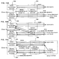
- Figure 15A to Figure 15C show three patterns, namely, case A, case B and case C as methods for reporting control information on reception of a timing adjustment control frame to the DSCH processing section 500. These three patterns will be described below.
- the macro diversity processing section 505 performs timing adjustment of the DCH in question within its own processing section, using the aforesaid adjustment value.
- the macro diversity processing section 505 reports this adjustment value and the mobile ID to the DSCH processing section 500.
- the DSCH processing section 500 is thereby able to adjust the timing offset amount corresponding to the mobile in question in the DSCH setting table 503, using the adjustment value and the mobile ID.
- the circuit terminating section 506 copies all of the uplink data that is transmitted on the dedicated channel terminated by the macro diversity processing section 505 and transmits this also to the DSCH processing section- 500.
- the DSCH processing section 500 is arranged to monitor, all the time, the uplink data on the dedicated channels that are received by transmission from the circuit terminating section 506 so as to receive only control data such as timing adjustment frames and discard ordinary user data. In this way, the DSCH processing section 500 can also learn the timing adjustment amount on the dedicated channels.
- a number of control frame dedicated channels equal to the number of dedicated channels are set up between the wireless network control device 303 and the base stations 304 and control frames are transmitted to the wireless network control device 303 from the base stations 304 on the dedicated channels.
- respective copied control frames are transmitted on the dedicated channel in question and the control frame dedicated channel in question after copying the control frame within the base station 304.
- DPCH dedicated channel
- a characteristic feature of service using multicast DSCH is that a service can be provided that is distributed by multicasting to mobiles that are in connected condition.
- one or several DSCH channels are normally set up for each area unit and changeover of the DSCH that is being received is performed when a mobile moves from a given area to another area.
- this may be said to constitute a further characteristic feature of multicast communication using DSCH in that different information can be distributed for different areas.
- DSCH cannot be received by mobiles that are not in a call-connected condition, there is no wasted power consumption due to multicast distribution to mobiles that are in an idle condition.
- a service may be provided displaying characteristic features for each geographical region by using different music data for each area. This is of course not restricted to music data and a similar service could be provided for all types of audible data.
- the current third-generation mobile communication technology inparticular, W-CDMA communication networks as specified by 3GPP, are not considered to provide an optimum method for realizing high rate multicast services in an efficient manner at the present time. This must have the effect of impeding the development of communications services which might be expected to offer high diversity in the future.
- efficient multicast services can be implemented simply by revising somewhat the DSCH technology in 3GPP. Also, by exploitation of the highly characteristic technical feature that "a distributed service allocated in area units can only be received during call connection", it is envisioned that various different types of services, which were hitherto difficult to implement, may be expected to become further developed, leading to expansion of the mobile communication market.
Landscapes
- Engineering & Computer Science (AREA)
- Computer Networks & Wireless Communication (AREA)
- Signal Processing (AREA)
- Mobile Radio Communication Systems (AREA)
Abstract
Description
Claims (40)
- A mobile communication system comprising:whereina wireless network control device connected to a network;a base station; andone or more mobiles connected with said base station,
data are transmitted from said wireless network control device to said one or more mobiles using a downlink shared channel,
a channel for transmitting multicast data is set up between data server means present on said network and said wireless network control device, and
said channel that is set up is mapped to said downlink shared channel. - The mobile communication system according to claim 1, further comprising,
mapping table means for storing the correspondence relationship of one or more channels and said downlink shared channel in said wireless network control device,
wherein
said channel for transmitting said multicast data is mapped to a suitable downlink shared channel by referencing said mapping table means. - The mobile communication system according to claim 2, wherein said mapping table means stores the identifiers of mobiles that are the subject of multicasting for each downlink shared channel and multicasting of data is performed in respect of mobiles that are indicated by said identifiers.
- The mobile communication system according to claim 1, further comprising,
mapping table means for storing the correspondence relationship of said downlink shared channel and dedicated channels that are set up for each mobile between core network and said wireless network, in said wireless network control device, wherein
said dedicated channels are mapped onto a suitable downlink shared channel by referencing saidmapping table means. - The mobile communication system according to claim 4, wherein said mapping table means stores the identifier of the mobile for each said dedicated channel and unicasts data in respect of the mobile indicated by said identifier.
- The mobile communication system according to claim 5, wherein said mapping table means stores a timing offset for each said dedicated channel and, when transmitting data using said dedicated channel, transmits data to a corresponding mobile with a transmission timing based on said timing offset.
- The mobile communication system according to any of claim 4 to 6, wherein said wireless network control device, when multicasting data on said downlink shared channel, selects mobiles to be the subj ect of multicasting by referencing said mapping table means and transmits signaling data with a suitable timing to all of the selected mobiles.
- The mobile communication system according to claim 7, wherein said wireless network control device stores identification information indicating that data is data that has been multicast within the data frame of said downlink shared channel that is transmitted, when performing multicasting of data using said downlink shared channel.
- The mobile communication system according to claim 8, wherein said mobile determines whether or not the received data frame of the downlink shared channel has been multicast by referencing said identification information.
- The mobile communication system according to claim 8, wherein said mobile performs ordinary unicast reception, if the identifier of said mobile is stored in the data frame of the downlink shared channel that is received by said mobile instead of a multicast identifier.
- The mobile communication system according to claim 8, wherein said mobile discards said received data, if the identifier that is stored in a data frame of the downlink shared channel that is received by said mobile is neither a multicast identifier nor the identifier of said mobile.
- The mobile communication system according to claim 2, wherein
said mobile receives an instruction to change over to the downlink shared channel from said wireless network control device, and
said mobile stores information indicating whether or not it participates in multicasting in said response message when said mobile transmits a response message in respect of said changeover instruction to said wireless network control device. - The mobile communication system according to claim 12, wherein said wireless network control device references the information indicating whether or not said mobile participates in multicasting that is stored in the response message with respect to said changeover instruction and, if this information indicates "participates", registers the mobile that has transmitted said response message in said mapping table means.
- The mobile communication system according to claim 6, wherein said timing offset information is updated when said wireless network control device receives control data prompting timing adjustment from said base station on a dedicated channel or a signaling data dedicated channel.
- The mobile communication system according to claim 1, wherein multicast data distribution is performed using said downlink shared channel only on mobiles that are in call-connected condition.
- The mobile communication system according to claim 15, wherein the distribution content is made different for each area when multicast data distribution is performed using said downlink shared channel only on mobiles that are in connected condition.
- A wireless network device connected to a network and a base station connected to a mobile, comprising:wherein shared channel processing comprises a mapping table that stores the correspondence relationship of one or more channels for transmitting multicast data, that are set up between a core network and said wireless network control device, and said downlink shared channel, anda main control section, a downlink shared channel processing section that performs downlink shared channel processing, a macro diversity processing section for implementing a macro diversity function, and a circuit terminating section respectively connected by internal bus means;
data is transmitted to said one or more mobiles with the channel for transmission of said multicast data mapped to an appropriate downlink shared channel by referencing said mapping table means. - The wireless network control device according to claim 17, wherein
said downlink shared channel processing section comprises a mapping table that stores the correspondence relationship of one or more downlink shared channels and a channel for transmission of multicast data set up between the core network and said wireless network control device, and
the channel for transmission of said multicast data is mapped to an appropriate downlink shared channel by referencing said mapping table means. - The wireless network control device according to claim 18, wherein said mapping table stores identifiers of mobiles that are the subject of multicasting for each said one or more downlink shared channels and multicasting of data is performed on mobiles indicated by said identifiers.
- The wireless network control device according to claim 17, wherein
said downlink shared channel processing section comprises a mapping table for storing the correspondence relationship of said downlink shared channel and a dedicated channel that is set up for each mobile between the core network and said wireless network, and
mapping of said dedicated channel to a suitable downlink shared channel is performed by referencing said mapping table. - The wireless network control device according to claim 20, wherein
said mapping table stores the identifier of a corresponding mobile for each said dedicated channel, and
data is unicast in respect of the mobile indicated by said identifier . - The wireless network control device according to claim 20, wherein
said mapping table stores a timing offset in said channel for each said dedicated channel, and
data is transmitted to the corresponding mobile with a transmission timing based on said timing offset when data is transmitted using said dedicated channel. - The wireless network control device according to claim 22, wherein
said downlink shared channel processing section comprises a downlink shared channel frame processing section,
said downlink shared channel frame processing section generates a downlink shared channel frame from multicast data and data intended for a specified mobile received from the core network, and
said downlink shared channel frame is transmitted together with signaling data to a mobile that is the subj ect of transmission. - The wireless network control device according to claim 23, wherein, if the data received from the core network is multicast data, said downlink shared channel frame processing section generates a downlink shared channel frame by applying an identifier indicating that said received data is multicast data to said received data.
- The wireless network control device according to claim 17, wherein
when multicasting data on said downlink shared channel, the mobiles to be the subj ects of multicasting are selected by referencing said mapping table, and
signaling data is transmitted with an appropriate timing to all of said mobiles. - The wireless network control device according to claim 25, wherein
as the channel used for transmission of said signaling data, a dedicated channel (DCH) is employed that is terminated by said macro diversity processing section,
said downlink shared channel processing section reports at least a signaling transmission instruction and the identifier of the mobile that is the subject of signaling transmission to said macro diversity processing section, and
after receiving said signaling transmission instruction and mobile identifier, said macro diversity processing section employs said dedicated channel to transmit signaling to said mobile. - The wireless network control device according to claim 25, wherein
a dedicated channel (DCH #0) that is terminated by said macro diversity processing section is employed as the channel that is used for said signaling data transmission and said signaling data is generated in said downlink shared channel processing section and transmitted, and
the signaling that is transmitted from said shared channel processing section is transmitted on a first channel (DCH #1) that is set up between said downlink shared channel processing section and circuit terminating section and, by merging said dedicated channel (DCH #0) and said first channel (DCH #1) at said circuit terminating section, the signaling data that is transmitted from said downlink shared channel processig section is transmitted on a dedicated channel for the corresponding mobile. - The wireless network control device according' to claim 25, wherein dedicated signaling channels are independently set up for each mobile in said downlink shared channel processing section as channels to be used for said signaling transmission and signaling data is transmitted to the corresponding mobile using said dedicated signaling channel.
- The wireless network control device according to claim 25, wherein
dedicated signaling channels are independently set up for each mobile in said macro diversity processing section as channels to be used for said signaling transmission,
said downlink shared channel processing section reports at least a signaling transmission instruction and the identifier of the mobile that is the subject of signaling transmission to said macro diversity processing section, and
after receiving said signaling transmission instruction and mobile identifier, said macro diversity processing section employs said dedicated signaling channel to transmit signaling to said mobile. - A mobile that is connected with a base station and receives data transmitted through a wireless network control device that is connected with a network, wherein
saidmobile references a data identifier that is stored in a downlink shared channel frame,
said mobile processes the received data as unicast data if said data identifier agrees with its own identifier, and
said mobile discards the received data if said data identifier is not a multicast identifier and does not agree with its own identifier. - The mobile according to claim 30, wherein after receiving an instruction to change over to the downlink shared channel identifier from said wireless network control device, when a response message is transmitted in respect of said changeover instruction to saidwireless network control device, information indicating whether or not said mobile participates in multicasting is stored in said response message.
- A wireless network control device that references the information as to whether or not the mobile participates in multicasting that is stored in said changeover response message that was transmitted by the mobile in claim 31, and, if this information indicates "participates", registers the mobile that has transmitted said response message in the mapping table.
- The wireless network control device according to claim 17, wherein, if said macro diversity processing section terminates a dedicated channel or dedicated signaling channel, and if a timing adjustment control cell is transmitted from the base station on said dedicated channel or dedicated signaling channel, said macro diversity processing section reports timing adjustment information extracted from said timing adjustment control cell together with the identifier of the mobile corresponding to said dedicated channel to said downlink shared channel processing section.
- The wireless network control device according to claim 33, wherein said downlink shared channel processing section updates the value of a region that stores the timing offset value in said mapping table, from the timing adjustment information and mobile identifier that were reported to said downlink shared channel processing section from said macro diversity processing section.
- The wireless network control device according to claim 33, wherein, if said macro diversity processing section terminates said dedicated channel or dedicated signaling channel, and if a timing adjustment control cell is transmitted from said base station on said dedicated channel or dedicated signaling channel, said circuit terminating section copies part or all of the data of said dedicated channel or dedicated signaling channel and transmits said copied data to said downlink shared channel processing section and thereby reports the timing adjustment information to said downlink shared channel processing section.
- The wireless network control device according to claim 35, wherein said downlink shared channel processing section receives all of said copied data and extracts only the timing adjustment control cell from said received data, the user data-being discarded.
- The wireless network control device according to claim 36, wherein the value of the storage region of the timing offset value in said mapping table is updated with the extracted timing adjustment value from said received timing adjustment control cell.
- The wireless network control device according to claim 33, wherein, if a dedicated channel or a dedicated signaling channel is terminated by said macro diversity processing section, and if a timing adjustment control cell is transmitted from said base station on said dedicated channel or dedicated signaling channel, a dedicated control frame channel is set up between said downlink shared channel processing section and the base station,
whereby transmission can be achieved on said dedicated control frame channel by copying said timing adjustment control cell in said base station. - The wireless network control device according to claim 33, wherein said DSCH processing section extracts a timing adjustment value from the timing adjustment control cell received by said dedicated control frame channel and updates the value of the storage region of the timing offset value in said mapping table.
- A mobile communication system comprising:whereina wireless network control device connected with a network;a base station; andone or more mobiles connected with said base station,
said mobile communication system being constructed such that data is transmitted from said wireless network control device to said one or more mobiles using a downlink shared channel, and
data being selectively multicast only in respect of specified mobiles during call connection.
Applications Claiming Priority (1)
| Application Number | Priority Date | Filing Date | Title |
|---|---|---|---|
| PCT/JP2002/005340 WO2003103320A1 (en) | 2002-05-31 | 2002-05-31 | Mobile communication system using downlink shared channel |
Publications (2)
| Publication Number | Publication Date |
|---|---|
| EP1511339A1 true EP1511339A1 (en) | 2005-03-02 |
| EP1511339A4 EP1511339A4 (en) | 2008-11-12 |
Family
ID=29606636
Family Applications (1)
| Application Number | Title | Priority Date | Filing Date |
|---|---|---|---|
| EP02728205A Withdrawn EP1511339A4 (en) | 2002-05-31 | 2002-05-31 | DOWNLINK SHARED CHANNEL MOBILE COMMUNICATIONS SYSTEM |
Country Status (4)
| Country | Link |
|---|---|
| US (9) | US7324497B2 (en) |
| EP (1) | EP1511339A4 (en) |
| JP (1) | JP4073434B2 (en) |
| WO (1) | WO2003103320A1 (en) |
Cited By (1)
| Publication number | Priority date | Publication date | Assignee | Title |
|---|---|---|---|---|
| WO2007052913A1 (en) * | 2005-11-03 | 2007-05-10 | Samsung Electronics Co., Ltd. | Method of generating and managing connection identifiers for supporting multicast for each group in ipv6-based wireless network and network interface using the method |
Families Citing this family (15)
| Publication number | Priority date | Publication date | Assignee | Title |
|---|---|---|---|---|
| WO2003103320A1 (en) * | 2002-05-31 | 2003-12-11 | 富士通株式会社 | Mobile communication system using downlink shared channel |
| KR101084142B1 (en) * | 2005-08-25 | 2011-11-17 | 엘지전자 주식회사 | Data transmission / reception method of downlink shared channel |
| US20070049305A1 (en) * | 2005-08-25 | 2007-03-01 | Lucent Technologies, Inc. | Method for adjusting timing of channels in a wireless communications system |
| JP4677490B2 (en) | 2005-10-31 | 2011-04-27 | エルジー エレクトロニクス インコーポレイティド | Wireless connection information transmission / reception method in wireless mobile communication system |
| AU2006309464B2 (en) | 2005-10-31 | 2009-10-29 | Lg Electronics Inc. | Method for processing control information in a wireless mobile communication system |
| US20070133449A1 (en) * | 2005-12-12 | 2007-06-14 | Mirko Schacht | Method for associating multiple users with a shared downlink channel |
| WO2007100084A1 (en) * | 2006-03-03 | 2007-09-07 | Matsushita Electric Industrial Co., Ltd. | Packet communication system and packet communication method |
| US8274956B2 (en) * | 2006-06-30 | 2012-09-25 | Qualcomm Incorporated | Standby time improvements using sub-networks |
| CN101480070A (en) * | 2006-07-04 | 2009-07-08 | 艾利森电话股份有限公司 | Broadcast and multicast on high speed downlink channels |
| KR20100072304A (en) * | 2007-09-24 | 2010-06-30 | 콸콤 인코포레이티드 | Method and apparatus for transmitting multiple multicast communications over a wireless communication network |
| US8532011B2 (en) | 2007-09-24 | 2013-09-10 | Qualcomm Incorporated | Method and apparatus for transmitting multiple multicast communications over a wireless communication network |
| JP4634429B2 (en) * | 2007-10-19 | 2011-02-16 | 富士通株式会社 | Mobile communication system using downlink shared channel |
| US8331278B2 (en) * | 2008-03-28 | 2012-12-11 | Qualcomm Incorporated | Managing an assignment of unicast traffic channels to access terminals participating in a multicast session within a wireless communications network |
| US9324122B2 (en) | 2012-10-19 | 2016-04-26 | Schweitzer Engineering Laboratories, Inc. | Voting scheme for time alignment |
| US9734109B2 (en) * | 2014-09-23 | 2017-08-15 | Raytheon Company | Multi-channel, selectable identity tagging data translator and method |
Family Cites Families (34)
| Publication number | Priority date | Publication date | Assignee | Title |
|---|---|---|---|---|
| US7606575B2 (en) * | 1988-08-04 | 2009-10-20 | Broadcom Corporation | Remote radio data communication system with data rate switching |
| JP2000009743A (en) * | 1998-06-19 | 2000-01-14 | Omron Corp | Sensor mounting structure |
| JP2000151622A (en) * | 1998-11-05 | 2000-05-30 | Oki Electric Ind Co Ltd | Medium access control method and system |
| KR100577149B1 (en) * | 1998-12-02 | 2006-07-25 | 엘지전자 주식회사 | Method for realizing multicasting service in mobile communication system |
| DE19856043A1 (en) * | 1998-12-04 | 2000-07-06 | Bosch Gmbh Robert | Data transfer device for centrally controlled mobile radio systems with broadcast control channel divided into data field for permanent broadcast information and data field for flexible broadcast information |
| US6741575B1 (en) * | 1999-02-26 | 2004-05-25 | Hughes Electronics Corporation | Apparatus and method for efficient delivery of multicast data over personal access communications system (PACS) |
| KR100567283B1 (en) | 1999-07-10 | 2006-04-05 | 유티스타콤코리아 유한회사 | Dynamic Channel Allocation Method in Mobile Communication System |
| JP3704003B2 (en) * | 1999-08-16 | 2005-10-05 | 株式会社東芝 | Radio base station apparatus, radio terminal apparatus, and information communication method |
| ATE418190T1 (en) * | 2000-01-14 | 2009-01-15 | Interdigital Tech Corp | WIRELESS COMMUNICATION SYSTEM WITH SELECTIVELY DIMENSIONED DATA TRANSPORT BLOCKS |
| US6785510B2 (en) | 2000-03-09 | 2004-08-31 | Salbu Resarch & Development (Proprietary) Limited | Routing in a multi-station network |
| US20020001296A1 (en) | 2000-04-10 | 2002-01-03 | Yu-Ro Lee | Data transmission method for hybrid ARQ type II/III downlink of wide-band radio communication system |
| US7254409B2 (en) * | 2000-04-14 | 2007-08-07 | Ntt Docomo, Inc. | Multicast service providing system, multicast service providing method, information distributor, radio terminal, and radio base station |
| JP3662473B2 (en) * | 2000-05-12 | 2005-06-22 | 株式会社エヌ・ティ・ティ・ドコモ | Multicast service providing method and information distribution apparatus |
| WO2002001769A2 (en) * | 2000-06-28 | 2002-01-03 | Telefonaktiebolaget Lm Ericsson (Publ) | Plural signaling channels for communicating signaling information to a user equipment terminal in a radio communications system |
| GB2364209A (en) * | 2000-06-30 | 2002-01-16 | Nokia Oy Ab | Combined digital video broadcast receiver and cellular receiver |
| US6804528B1 (en) * | 2000-11-03 | 2004-10-12 | Lucent Technologies, Inc. | Apparatus and method for use in the multicast of traffic data in wireless multiple access communications systems |
| US7116641B2 (en) * | 2000-11-15 | 2006-10-03 | Lg Electronics Inc. | Multicast and broadcast transmission method and apparatus of a CDMA mobile communication network |
| US6970438B2 (en) * | 2001-02-16 | 2005-11-29 | Nokia Mobile Phones Ltd. | Method and device for downlink packet switching |
| US6975868B2 (en) * | 2001-02-21 | 2005-12-13 | Qualcomm Incorporated | Method and apparatus for IS-95B reverse link supplemental code channel frame validation and fundamental code channel rate decision improvement |
| US6611510B2 (en) * | 2001-06-18 | 2003-08-26 | Telcordia Technologies Inc. | Method and system for soft handoff of mobile terminals in IP wireless networks. |
| DE10132273A1 (en) * | 2001-07-04 | 2003-01-23 | Siemens Ag | Method for transmitting multicast messages in a radio system, and a correspondingly designed radio system and a correspondingly designed transmitter and receiver |
| US6781999B2 (en) * | 2001-07-23 | 2004-08-24 | Airvana, Inc. | Broadcasting and multicasting in wireless communication |
| EP1423927B1 (en) * | 2001-09-06 | 2008-05-07 | Gilat Satellite Networks Ltd. | Dual channel two-way satellite communication |
| US7058040B2 (en) * | 2001-09-21 | 2006-06-06 | Schmidt Dominik J | Channel interference reduction |
| DE60126998T2 (en) * | 2001-10-19 | 2007-12-13 | Nokia Corp. | TRANSMISSION OF MULTICAST AND BROADCAST MULTIMEDIA SERVICES VIA A RADIO INTERFACE |
| US6993327B2 (en) * | 2001-10-29 | 2006-01-31 | Motorola, Inc. | Multicast distribution of presence information for an instant messaging system |
| US6987764B2 (en) * | 2001-11-05 | 2006-01-17 | Qualcomm, Incorporated | Method and apparatus for selecting a packet data serving node for multi-cast/broadcast services |
| US7075904B1 (en) * | 2001-11-16 | 2006-07-11 | Sprint Spectrum L.P. | Method and system for multicasting messages to select mobile recipients |
| US7292854B2 (en) * | 2002-02-15 | 2007-11-06 | Lucent Technologies Inc. | Express signaling in a wireless communication system |
| US7054643B2 (en) * | 2002-02-20 | 2006-05-30 | Nokia Corporation | System for rate control of multicast data delivery in a wireless network |
| US7177658B2 (en) * | 2002-05-06 | 2007-02-13 | Qualcomm, Incorporated | Multi-media broadcast and multicast service (MBMS) in a wireless communications system |
| WO2003103320A1 (en) * | 2002-05-31 | 2003-12-11 | 富士通株式会社 | Mobile communication system using downlink shared channel |
| KR100893070B1 (en) * | 2002-09-19 | 2009-04-17 | 엘지전자 주식회사 | Method and apparatus for providing and receiving multicast service in wireless communication system |
| US7606205B2 (en) * | 2002-10-28 | 2009-10-20 | Nokia Corporation | System and method for providing selection diversity for multicasting content |
-
2002
- 2002-05-31 WO PCT/JP2002/005340 patent/WO2003103320A1/en not_active Ceased
- 2002-05-31 JP JP2004510269A patent/JP4073434B2/en not_active Expired - Fee Related
- 2002-05-31 EP EP02728205A patent/EP1511339A4/en not_active Withdrawn
-
2004
- 2004-11-24 US US10/999,206 patent/US7324497B2/en not_active Expired - Fee Related
-
2007
- 2007-04-02 US US11/730,546 patent/US20070177563A1/en not_active Abandoned
- 2007-04-03 US US11/730,668 patent/US20070183356A1/en not_active Abandoned
- 2007-04-03 US US11/730,667 patent/US20070248074A1/en not_active Abandoned
- 2007-04-03 US US11/730,666 patent/US20070177564A1/en not_active Abandoned
-
2008
- 2008-10-10 US US12/285,680 patent/US8331376B2/en not_active Expired - Fee Related
- 2008-10-14 US US12/285,787 patent/US20090046620A1/en not_active Abandoned
- 2008-11-11 US US12/268,890 patent/US20090067380A1/en not_active Abandoned
-
2010
- 2010-04-15 US US12/761,124 patent/US20100195559A1/en not_active Abandoned
Cited By (2)
| Publication number | Priority date | Publication date | Assignee | Title |
|---|---|---|---|---|
| WO2007052913A1 (en) * | 2005-11-03 | 2007-05-10 | Samsung Electronics Co., Ltd. | Method of generating and managing connection identifiers for supporting multicast for each group in ipv6-based wireless network and network interface using the method |
| US7760666B2 (en) | 2005-11-03 | 2010-07-20 | Samsung Electronics, Co., Ltd. | Method of generating and managing connection identifiers for supporting multicast for each group in IPv6-based wireless network and network interface using the method |
Also Published As
| Publication number | Publication date |
|---|---|
| US20070248074A1 (en) | 2007-10-25 |
| JP4073434B2 (en) | 2008-04-09 |
| US20090067380A1 (en) | 2009-03-12 |
| US20050122950A1 (en) | 2005-06-09 |
| US8331376B2 (en) | 2012-12-11 |
| WO2003103320A1 (en) | 2003-12-11 |
| US20070177563A1 (en) | 2007-08-02 |
| US20070177564A1 (en) | 2007-08-02 |
| US20070183356A1 (en) | 2007-08-09 |
| US20090046689A1 (en) | 2009-02-19 |
| US20090046620A1 (en) | 2009-02-19 |
| EP1511339A4 (en) | 2008-11-12 |
| US7324497B2 (en) | 2008-01-29 |
| US20100195559A1 (en) | 2010-08-05 |
| JPWO2003103320A1 (en) | 2005-10-06 |
Similar Documents
| Publication | Publication Date | Title |
|---|---|---|
| US8331376B2 (en) | Mobile communication system using a downlink shared channel | |
| JP4755675B2 (en) | Multimedia service method in wireless mobile communication system | |
| EP0522772B1 (en) | Wireless access telephone-to-telephone network interface architecture | |
| US8068843B2 (en) | Method for increasing system capacity by transmitting control Signal for MBMS data by combining RLC and PDCP messages | |
| JP4680457B2 (en) | System and method for performing soft handoff between frequency division duplex and time division duplex communication systems | |
| KR100943901B1 (en) | Wireless Protocol Entity Sharing for Broadcast and Multicast | |
| JP3996082B2 (en) | Method for performing Iu-Flex based MBMS | |
| CN106533888A (en) | Gateway equipment for implementing digital cluster interconnection and interworking | |
| EP1743450B1 (en) | Optimised iub transport | |
| JP4634429B2 (en) | Mobile communication system using downlink shared channel | |
| EP1253797A2 (en) | Communication system, communication unit and method for dynamically changing an encryption key | |
| FI109168B (en) | Procedure for controlling the connections to a mobile station | |
| HK1077135B (en) | Multimedia service providing method in a radio mobile communication system |
Legal Events
| Date | Code | Title | Description |
|---|---|---|---|
| PUAI | Public reference made under article 153(3) epc to a published international application that has entered the european phase |
Free format text: ORIGINAL CODE: 0009012 |
|
| 17P | Request for examination filed |
Effective date: 20041129 |
|
| AK | Designated contracting states |
Kind code of ref document: A1 Designated state(s): AT BE CH CY DE DK ES FI FR GB GR IE IT LI LU MC NL PT SE TR |
|
| RBV | Designated contracting states (corrected) |
Designated state(s): DE FR GB IT |
|
| A4 | Supplementary search report drawn up and despatched |
Effective date: 20081010 |
|
| 17Q | First examination report despatched |
Effective date: 20100721 |
|
| 18D | Application deemed to be withdrawn |
Effective date: 20131202 |
|
| REG | Reference to a national code |
Ref country code: DE Ref legal event code: R079 Free format text: PREVIOUS MAIN CLASS: H04Q0007360000 Ipc: H04W0016000000 |
|
| REG | Reference to a national code |
Ref country code: DE Ref legal event code: R079 Free format text: PREVIOUS MAIN CLASS: H04Q0007360000 Ipc: H04W0016000000 Effective date: 20140526 |
|
| STAA | Information on the status of an ep patent application or granted ep patent |
Free format text: STATUS: THE APPLICATION IS DEEMED TO BE WITHDRAWN |
|
| R18D | Application deemed to be withdrawn (corrected) |
Effective date: 20131203 |