EP1510884A1 - Heat roller and heat roller manufacturing method - Google Patents
Heat roller and heat roller manufacturing method Download PDFInfo
- Publication number
- EP1510884A1 EP1510884A1 EP02730883A EP02730883A EP1510884A1 EP 1510884 A1 EP1510884 A1 EP 1510884A1 EP 02730883 A EP02730883 A EP 02730883A EP 02730883 A EP02730883 A EP 02730883A EP 1510884 A1 EP1510884 A1 EP 1510884A1
- Authority
- EP
- European Patent Office
- Prior art keywords
- sheet
- heating element
- heat roller
- tube
- inner tube
- Prior art date
- Legal status (The legal status is an assumption and is not a legal conclusion. Google has not performed a legal analysis and makes no representation as to the accuracy of the status listed.)
- Granted
Links
Images



Classifications
-
- G—PHYSICS
- G03—PHOTOGRAPHY; CINEMATOGRAPHY; ANALOGOUS TECHNIQUES USING WAVES OTHER THAN OPTICAL WAVES; ELECTROGRAPHY; HOLOGRAPHY
- G03G—ELECTROGRAPHY; ELECTROPHOTOGRAPHY; MAGNETOGRAPHY
- G03G15/00—Apparatus for electrographic processes using a charge pattern
- G03G15/20—Apparatus for electrographic processes using a charge pattern for fixing, e.g. by using heat
- G03G15/2003—Apparatus for electrographic processes using a charge pattern for fixing, e.g. by using heat using heat
- G03G15/2014—Apparatus for electrographic processes using a charge pattern for fixing, e.g. by using heat using heat using contact heat
- G03G15/2053—Structural details of heat elements, e.g. structure of roller or belt, eddy current, induction heating
-
- G—PHYSICS
- G03—PHOTOGRAPHY; CINEMATOGRAPHY; ANALOGOUS TECHNIQUES USING WAVES OTHER THAN OPTICAL WAVES; ELECTROGRAPHY; HOLOGRAPHY
- G03G—ELECTROGRAPHY; ELECTROPHOTOGRAPHY; MAGNETOGRAPHY
- G03G13/00—Electrographic processes using a charge pattern
- G03G13/20—Fixing, e.g. by using heat
-
- G—PHYSICS
- G03—PHOTOGRAPHY; CINEMATOGRAPHY; ANALOGOUS TECHNIQUES USING WAVES OTHER THAN OPTICAL WAVES; ELECTROGRAPHY; HOLOGRAPHY
- G03G—ELECTROGRAPHY; ELECTROPHOTOGRAPHY; MAGNETOGRAPHY
- G03G15/00—Apparatus for electrographic processes using a charge pattern
- G03G15/20—Apparatus for electrographic processes using a charge pattern for fixing, e.g. by using heat
- G03G15/2003—Apparatus for electrographic processes using a charge pattern for fixing, e.g. by using heat using heat
- G03G15/2014—Apparatus for electrographic processes using a charge pattern for fixing, e.g. by using heat using heat using contact heat
- G03G15/2053—Structural details of heat elements, e.g. structure of roller or belt, eddy current, induction heating
- G03G15/2057—Structural details of heat elements, e.g. structure of roller or belt, eddy current, induction heating relating to the chemical composition of the heat element and layers thereof
-
- G—PHYSICS
- G03—PHOTOGRAPHY; CINEMATOGRAPHY; ANALOGOUS TECHNIQUES USING WAVES OTHER THAN OPTICAL WAVES; ELECTROGRAPHY; HOLOGRAPHY
- G03G—ELECTROGRAPHY; ELECTROPHOTOGRAPHY; MAGNETOGRAPHY
- G03G15/00—Apparatus for electrographic processes using a charge pattern
- G03G15/20—Apparatus for electrographic processes using a charge pattern for fixing, e.g. by using heat
- G03G15/2003—Apparatus for electrographic processes using a charge pattern for fixing, e.g. by using heat using heat
- G03G15/2014—Apparatus for electrographic processes using a charge pattern for fixing, e.g. by using heat using heat using contact heat
- G03G15/206—Structural details or chemical composition of the pressure elements and layers thereof
-
- G—PHYSICS
- G03—PHOTOGRAPHY; CINEMATOGRAPHY; ANALOGOUS TECHNIQUES USING WAVES OTHER THAN OPTICAL WAVES; ELECTROGRAPHY; HOLOGRAPHY
- G03G—ELECTROGRAPHY; ELECTROPHOTOGRAPHY; MAGNETOGRAPHY
- G03G15/00—Apparatus for electrographic processes using a charge pattern
- G03G15/20—Apparatus for electrographic processes using a charge pattern for fixing, e.g. by using heat
- G03G15/2003—Apparatus for electrographic processes using a charge pattern for fixing, e.g. by using heat using heat
- G03G15/2014—Apparatus for electrographic processes using a charge pattern for fixing, e.g. by using heat using heat using contact heat
- G03G15/2064—Apparatus for electrographic processes using a charge pattern for fixing, e.g. by using heat using heat using contact heat combined with pressure
-
- H—ELECTRICITY
- H05—ELECTRIC TECHNIQUES NOT OTHERWISE PROVIDED FOR
- H05B—ELECTRIC HEATING; ELECTRIC LIGHT SOURCES NOT OTHERWISE PROVIDED FOR; CIRCUIT ARRANGEMENTS FOR ELECTRIC LIGHT SOURCES, IN GENERAL
- H05B3/00—Ohmic-resistance heating
- H05B3/0095—Heating devices in the form of rollers
-
- G—PHYSICS
- G03—PHOTOGRAPHY; CINEMATOGRAPHY; ANALOGOUS TECHNIQUES USING WAVES OTHER THAN OPTICAL WAVES; ELECTROGRAPHY; HOLOGRAPHY
- G03G—ELECTROGRAPHY; ELECTROPHOTOGRAPHY; MAGNETOGRAPHY
- G03G2215/00—Apparatus for electrophotographic processes
- G03G2215/20—Details of the fixing device or porcess
- G03G2215/2003—Structural features of the fixing device
- G03G2215/2058—Shape of roller along rotational axis
- G03G2215/2061—Shape of roller along rotational axis concave
-
- Y—GENERAL TAGGING OF NEW TECHNOLOGICAL DEVELOPMENTS; GENERAL TAGGING OF CROSS-SECTIONAL TECHNOLOGIES SPANNING OVER SEVERAL SECTIONS OF THE IPC; TECHNICAL SUBJECTS COVERED BY FORMER USPC CROSS-REFERENCE ART COLLECTIONS [XRACs] AND DIGESTS
- Y10—TECHNICAL SUBJECTS COVERED BY FORMER USPC
- Y10T—TECHNICAL SUBJECTS COVERED BY FORMER US CLASSIFICATION
- Y10T29/00—Metal working
- Y10T29/49—Method of mechanical manufacture
- Y10T29/49002—Electrical device making
- Y10T29/49082—Resistor making
- Y10T29/49083—Heater type
Definitions
- the present invention relates to a heat roller and a method of fabricating the same.
- the present invention relates to, for example, a heat roller suitable for use in a fixing device used in an electrophotographic device.
- An electrophotographic device (copying machine, facsimile device, printer and the like) has an image forming device and a fixing device for fixing an image formed and transferred onto a sheet by the image forming device.
- the fixing device includes a heat roller.
- a heat roller is formed of a metallic ring member, rubber covering the metallic ring member and a halogen lamp arranged inside the metallic ring member.
- the halogen lamp is low in thermal efficiency, and moreover, the rubber covering the metallic ring member reduces the thermal efficiency. In addition, it takes several ten seconds to several minutes to reach a predetermined temperature, so that a preheating is required during a stand-by period.
- a directly-heated heat roller including a sheet-like heating element in which a resistance member is embedded in an insulating member.
- This heat roller has high thermal efficiency, since the resistance member generates heat when electric current flows through the resistance member and the heat is conducted thereby to heat a sheet directly.
- the sheet-like heating element is at first formed as a flat heating sheet.
- the heating sheet is rounded to form a cylindrical sheet-like heating element.
- the sheet-like heating element cannot keep its cylindrical shape with this state, so that it is attached on an inner surface of a metallic cylindrical tube for use. However, attaching the sheet-like heating element onto the inner surface of the cylindrical tube is difficult work.
- a method for fabricating a heat roller wherein a cylindrical sheet-like heating element is sandwiched between an inner tube and an outer tube that compose a duplex tube. Firstly, the inner tube is arranged on the inner surface side of the cylindrical sheet-like heating element, and then, the outer tube is arranged on the outer surface side of this heating element. Then, pressurized fluid is supplied to the inner tube to expand the inner tube and the sheet-like heating element toward the outer tube, whereby the sheet-like heating element is brought into intimate contact with the inner tube and the outer tube. In this fabrication process, it is unnecessary that the sheet-like heating element is brought into contact with the inner tube and with the outer tube, thereby providing a simple assembling operation.
- the surface of the heat roller is finished to have a desired shape with a turning machine. If the heat roller is used in the fixing device, for example, the surface of the heat roller is desired to be finished into a reverse-crown shape. Further, a convex section or a concave section is provided at the edge section of the heat roller in order to attach the heat roller to a shaft, or a gear is attached.
- the present invention aims to provide a heat roller including a sheet-like heating element, an inner tube and an outer tube and capable of being easily manufactured into a desired shape.
- a heat roller according to the present invention includes a cylindrical sheet-like heating element having a resistance member embedded in an insulating member, an inner tube that comes in intimate contact with an inner surface of the sheet-like heating element and an outer tube that comes in intimate contact with an outer surface of the sheet-like heating element, wherein the outer tube has a non-linear shape seen in an axial direction.
- the heat roller according to the present invention can be used, for example, in a fixing device, has high thermal efficiency and can relatively simply be fabricated.
- the outer tube is preferably formed into a reverse-crown shape seen in the axial direction.
- a method of fabricating a heat roller, including a cylindrical sheet-like heating element having a resistance member embedded in an insulating member, an inner tube that comes in intimate contact with the inner surface of the sheet-like heating element and an outer tube that comes in intimate contact with the outer surface of the sheet-like heating element, is such that the inner tube is arranged on the inner surface side of the sheet-like heating element, the outer tube is arranged on the outer surface side of the sheet-like heating element, the inner tube, sheet-like heating element and outer tube are inserted into a die having a non-linear inner shape seen in the axial direction, pressurized fluid is supplied to the inner tube to expand the inner tube, sheet-like heating element and outer tube toward the die for forming the outer tube so as to match with the inner shape of the die.
- the heat roller having, for example, a reverse-crown shape can easily be fabricated.
- a method of fabricating a heat roller including a cylindrical sheet-like heating element having a resistance member embedded in an insulating member, an inner tube that comes in intimate contact with an inner surface of the sheet-like heating element and an outer tube that comes in intimate contact with an outer surface of the sheet-like heating element, is such that the inner tube is arranged on the inner surface side of the sheet-like heating element, the outer tube is arranged on the outer surface side of the sheet-like heating element, the inner tube, sheet-like heating element and outer tube are inserted into a die having a convex section or a concave section at its edge section, pressurized fluid is supplied to the inner tube to expand the inner tube, sheet-like heating element and outer tube toward the die for forming the edge section of the inner tube into a shape having a convex section or a concave section corresponding to the convex section or the concave section of the die.
- a method of fabricating a heat roller including a cylindrical sheet-like heating element having a resistance member embedded in an insulating member, an inner tube that comes in intimate contact with an inner surface of the sheet-like heating element and an outer tube that comes in intimate contact with an outer surface of the sheet-like heating element, is such that the inner tube is arranged on the inner surface side of the sheet-like heating element, the outer tube is arranged on the outer surface side of the sheet-like heating element, the inner tube, sheet-like heating element and outer tube are inserted into a die, a ring member is arranged at an edge section of the inner tube, pressurized fluid is supplied to the inner tube to expand the inner tube, sheet-like heating element and outer tube toward the die for forming the edge section of the inner tube so as to match with the inner shape of the die and the ring member is fixed to the edge section of the inner tube.
- FIG. 1 is a side view showing a fixing device including a heat roller according to one embodiment of the present invention.
- a fixing device 10 includes a heat roller 12 and a pressure roller 14 that is pressed into contact with the heat roller 12 and is covered with rubber.
- a sheet 16 is transported between the heat roller 12 and the pressure roller 14, whereupon toner carried by the sheet 16 is melted by heat generated by the heat roller 12 and is pressurized between the heat roller 12 and the pressure roller 14, to thereby be fixed.
- FIG. 2 is a side view showing a fixing device including a heat roller according to another embodiment of the present invention.
- a fixing device 10 includes a heat roller 12 and a heat roller 18, serving as a pressure roller, that is pressed into contact with the heat roller 12.
- the heat roller 18 has a configuration similar to that of the heat roller 12. In this case, a toner carried by the sheet 16 is melted by heat generated by the heat rollers 12 and 18 and is pressurized to be fixed.
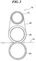
- FIG. 3 is a side view showing another example of a fixing device including the heat roller according to the present invention.
- a fixing device 10 has the heat roller 12, fixing roller 20, belt 22 bridged to the heat roller 12 and the fixing roller 20 and a pressure roller 24 that is pressed in contact with the fixing roller 20 via the belt 22.
- heat generated by the heat roller 12 is transmitted to the sheet 16 via the belt 22, whereby toner carried by the sheet 16 is melted by the heat generated by the heat roller 12, pressurized, and then, fixed.
- a heat roller can be used instead of the pressure roller 24.
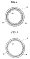
- Figs. 4 and 5 are sectional views each showing the heat roller 12 shown in Figs. 1 to 3.
- Fig. 4 shows the heat roller 12 before the tube expansion (during the fabrication process), while
- Fig. 5 shows the heat roller 12 after the tube expansion.
- the heat roller 12 includes the cylindrical sheet-like heating element 26, the inner tube 28 that comes in intimate contact with the inner surface of the sheet-like heating element 26 and the outer tube 30 that comes in intimate contact with the outer surface of the heating element 26.
- a gap is present between the sheet-like heating element 26 and the inner tube 28 and a gap is present between the sheet-like heating element 26 and the outer tube 30.
- Fig. 6 is a sectional view showing the heat roller 12 taken along a line VI-VI in Fig. 7.
- the sheet-like heating element 26 has a heating sheet 26a wherein a resistance member 32 is embedded in insulating members 34 and 36.
- the resistance member 32 is formed on the insulating member 34 and covered with the insulating member 36.
- the insulating members are made of a polyimide type heat-resistant resin and the resistance member 32 is made of stainless steel.
- the heating sheet 26a is formed as a flat sheet. It is rounded to join both ends of the sheet, to thereby be formed into the cylindrical sheet-like heating element 26.
- the inner tube 28 is made of a relatively soft aluminum type material so as to be deformable while the outer tube 30 is made of a relatively hard aluminum type material such that the heat roller 12 keeps the cylindrical shape.
- Fig. 7 is a plan view showing a pattern of the resistance member 32 on the insulating member 34 of the heating sheet 26a.
- the resistance member 32 is formed on the insulating member 34 so as to meander.
- the insulating member 36 is laminated on the insulating member 34 having the resistance member 32 formed thereon. Electric current flows through both ends of the resistance member 32, so that the resistance member 32 generates heat, and the generated heat is transmitted to the sheet 16 via the outer tube 30.
- Figs. 8 and 9 are sectional views showing a fabrication process of the heat roller 12.
- Fig. 8 shows a step before the tube expansion while
- Fig. 9 shows a tube expansion step.
- an outer shape die for tube expansion formed of an upper die 38 and lower die 40 is prepared.
- the outer shape die for tube expansion formed of an upper die 38 and lower die 40 has non-linear inner shapes 38a and 40a.
- a pressurized fluid supplying tube 42 and a pressurized fluid discharging tube 44 are prepared.
- a heat roller assembly having the cylindrical sheet-like heating element 26, inner tube 28 and outer tube 30 is inserted into the outer shape die for tube expansion having the upper die 38 and the lower die 40.
- the inner tube 28 is arranged at the inside of the sheet-like heating element 26 while the outer tube 30 is arranged at the outside thereof.
- a gap may be formed between the sheet-like heating element 26 and the inner tube 28 and a gap may be formed between the sheet-like heating element 26 and the outer tube 30, whereby the heat roller assembly can easily be assembled.
- the sheet-like heating element 26 may be in partial contact with the inner tube 28 and with the outer tube 30.
- the pressurized fluid supplying tube 42 and the pressurized fluid discharging tube 44 are connected to the edge section of the inner tube 28, and then, the upper die 38 and the lower die 40 are brought close to each other to close the outer shape die for tube expansion.
- Pressurized fluid e.g., water
- Pressurized fluid e.g., water
- the inner tube 28 is expanded and brought into intimate contact with the sheet-like heating element 26 to thereby expand the sheet-like heating element 26, whereby the sheet-like heating element 26 is brought into intimate contact with the outer tube 30 to thereby expand the outer tube 30.
- the expansion of the outer tube 30 is restricted by the outer shape die for tube expansion formed of the upper die 38 and the lower die 40.
- the heat roller assembly including the sheet-like heating element 26, inner tube 28 and outer tube 30 is expanded toward the outer shape die for tube expansion, with the result that the inner tube 28 is brought into intimate contact with the sheet-like heating element 26 and the sheet-like heating element 26 is brought into intimate contact with the outer tube 30, and further, the outer tube 30 is formed so as to match with the inner shape of the outer shape die for tube expansion.
- the inner shapes 38a and 40a of the upper die 38 and the lower die 40 are formed into a crown shape in which a center section in the longitudinal direction rises.
- Fig. 10 is a front view showing the heat roller 12 fabricated by the fabrication process of the heat roller shown in Figs. 9 and 10.
- the outer tube 30 formed by the outer shape die having a crown-shaped cavity is formed into a reverse-crown shape.
- the outer tube 30 has a small-diameter section 30a at its center and a taper section 30b whose diameter is widened toward the edge section from the small-diameter section 30a at the center.
- the outer tube 30 has a non-linear shape in the axial direction.
- the outer tube 30 is not formed such that only the outer surface of the outer tube 30 is formed into the reverse-crown shape like the case where the outer surface of the outer tube 30 is cut by a turning machine, but formed such that the inner surface of the outer tube 30 is also formed into the reverse-crown shape.
- a broken line represents a cylindrical surface connecting both edge sections of the outer tube 30.
- the difference between the diameter of the small-diameter section 30a at the center of the outer tube 30 and the diameter of both edge sections of the outer tube 30 of the heat roller 12 does not necessarily have to be so great.
- the difference between the diameter of the small-diameter section 30a and the diameter of both edge sections may be about 0.1 mm.
- the heat roller 12 formed into a reverse-crown shape can prevent the sheet 16 from being wrinkled or can prevent that the pressure distribution in the axial direction becomes non-uniform.
- the directly-heated heat roller 12 including the sheet-like heating element 26 and having a reverse-crown shape can easily be fabricated.
- assembling and tube expansion of the directly-heated heat roller 12 can be performed simultaneously with the formation of the outer shape, thereby being capable of accomplishing remarkably reduced cost.
- Fig. 11 is a front view showing a heat roller according to another embodiment of the present invention.
- the heat roller 12 includes, as explained with reference to Figs. 4 to 7, the sheet-like heating element 26, inner tube 28 and outer tube 30.
- the heat roller 12 is, as explained with reference to Figs. 8 and 9, fabricated in the same manner using the outer shape die formed of the upper die 38 and the lower die 40.
- the upper die 38 and the lower die 40 are partially represented in Fig. 11.
- the heat roller 12 is formed according to the outer shape die for tube expansion with the upper die 38 and the lower die 40 and a step section 28a having a convex section and concave section is formed at the edge section of the inner tube 28 at the edge section of the heat roller 12, when the heat roller 12 is fabricated in a manner as explained with reference to Figs. 8 and 9.
- a bearing for example, can be attached to this step section 28a.
- An external electrode can also be attached to this step section 28a, for example.
- the outer tube 30 is preferably formed into a reverse-taper shape, but it may have a cylindrical shape.
- Fig. 12 is a front view showing a modified example of the heat roller shown in Fig. 11.
- the outer shape die formed of the upper die 38 and the lower die 40 is used as explained with reference to Figs. 8 and 9.
- Fig. 12 only the upper die 38 is represented.
- the upper die 38 has a convex section 38c at its edge section.
- the heat roller 12 is formed according to the outer shape die for tube expansion composed of the upper die 38 and the lower die 40, and a concave section 28b is formed at the edge section of the inner tube 28 at the edge section of the heat roller 12.
- An O-ring, an E-ring or a snap ring, for example, can be attached to this concave section 28b.
- Fig. 13 is a front view showing a modified example of the heat roller shown in Fig. 11.
- the outer shape die formed of the upper die 38 and the lower die 40 is used as explained with reference to Figs. 8 and 9.
- Fig. 13 only the upper die 38 is represented.
- the upper die 38 has a concave section 38d at its edge section.
- the heat roller 12 is formed according to the outer shape die for tube expansion with the upper die 38 and the lower die 40, and a convex section 28c is formed at the edge section of the inner tube 28 at the edge section of the heat roller 12.
- This convex section 28c can be used, for example, as a stopper for attaching a ring member such as a snap ring.
- Fig. 14 is a sectional view showing a step before the tube expansion of the fabrication process of the heat roller according to another example.
- Fig. 15 is a sectional view showing a tube expansion step of the fabrication process of the heat roller.
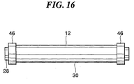
- Fig. 16 is a front view showing the heat roller fabricated by the fabrication process of the heat roller shown in Figs. 14 and 15.
- the heat roller 12 includes the sheet-like heating element 26, inner tube 28 and outer tube 30 as explained with reference to Figs. 4 to 7.
- the heat roller 12 is fabricated in the same manner using the outer shape die for tube expansion with the upper die 38 and the lower die 40, as explained with reference to Figs. 8 and 9.
- a flange (ring member) 46 is fitted to the exposed edge section of the sheet-like heating element 26 of the heat roller 12.
- the upper die 38 and the lower die 40 have concave sections 38e and 40e at the position corresponding to the flange 46.
- the flange 46 is made separate from the heat roller 12 with a resinous material or a metallic material, and attached to the heat roller 12.
- the flange 46 has a concave section 46a at the inside thereof.
- the heat roller 12 is formed according to the outer shape die for tube expansion with the upper die 38 and the lower die 40, and the flange 46 can be fixed to the heat roller 12.
- the flange 46 can be used for various objects.
- a gear can be attached to the flange 46.
- the flange 46 may be a part of a conductive member for electrically connecting the resistance member 32 of the sheet-like heating element 26 and a power source.
- the present invention can provide various heat rollers each having various outer shape specification with low cost. Further, the present invention can provide a heat roller capable of reducing processing cost for performing positioning or fixation in installing an external electrode, bearing, flange and the like.
Landscapes
- Physics & Mathematics (AREA)
- General Physics & Mathematics (AREA)
- Fixing For Electrophotography (AREA)
- Control Of Resistance Heating (AREA)
- Resistance Heating (AREA)
Abstract
Description
Claims (5)
- A heat roller comprising a cylindrical sheet-like heating element having a resistance member embedded in an insulating member, an inner tube that comes in intimate contact with an inner surface of the sheet-like heating element and an outer tube that comes in intimate contact with an outer surface of the sheet-like heating element, wherein the outer tube has a non-linear shape seen in an axial direction.
- The heat roller according to Claim 1, wherein the outer tube is preferably formed into a reverse-crown shape seen in the axial direction.
- A method of fabricating a heat roller comprising a cylindrical sheet-like heating element having a resistance member embedded in an insulating member, an inner tube that comes in intimate contact with an inner surface of the sheet-like heating element and an outer tube that comes in intimate contact with an outer surface of the sheet-like heating element, comprising:arranging the inner tube on the inner surface side of the sheet-like heating element;arranging the outer tube on the outer surface side of the sheet-like heating element;inserting the inner tube, sheet-like heating element and outer tube into a die having a non-linear inner shape seen in an axial direction; andsupplying pressurized fluid to the inner tube to expand the inner tube, sheet-like heating element and outer tube toward the die for forming the outer tube so as to match with the inner shape of the die.
- A method of fabricating a heat roller comprising a cylindrical sheet-like heating element having a resistance member embedded in an insulating member, an inner tube that comes in intimate contact with an inner surface of the sheet-like heating element and an outer tube that comes in intimate contact with an outer surface of the sheet-like heating element, comprising:arranging the inner tube on the inner surface side of the sheet-like heating element;arranging the outer tube on the outer surface side of the sheet-like heating element;inserting the inner tube, sheet-like heating element and outer tube into a die having a convex section or a concave section at its edge section; andsupplying pressurized fluid to the inner tube to expand the inner tube, sheet-like heating element and outer tube toward the die for forming the edge section of the inner tube into a shape having a convex section or a concave section corresponding to the convex section or the concave section of the die.
- A method of fabricating a heat roller comprising a cylindrical sheet-like heating element having a resistance member embedded in an insulating member, an inner tube that comes in intimate contact with an inner surface of the sheet-like heating element and an outer tube that comes in intimate contact with an outer surface of the sheet-like heating element comprising:arranging the inner tube on the inner surface side of the sheet-like heating element;arranging the outer tube on the outer surface side of the sheet-like heating element;inserting the inner tube, sheet-like heating element and outer tube into a die,arranging a ring member at an edge section of the inner tube, andsupplying pressurized fluid to the inner tube to expand the inner tube, sheet-like heating element and outer tube toward the die for forming the edge section of the inner tube so as to match with the inner shape of the die and the ring member is fixed to the edge section of the inner tube.
Applications Claiming Priority (1)
| Application Number | Priority Date | Filing Date | Title |
|---|---|---|---|
| PCT/JP2002/005444 WO2003102700A1 (en) | 2002-06-03 | 2002-06-03 | Heat roller and heat roller manufacturing method |
Publications (3)
| Publication Number | Publication Date |
|---|---|
| EP1510884A1 true EP1510884A1 (en) | 2005-03-02 |
| EP1510884A4 EP1510884A4 (en) | 2009-03-25 |
| EP1510884B1 EP1510884B1 (en) | 2010-07-14 |
Family
ID=29606662
Family Applications (1)
| Application Number | Title | Priority Date | Filing Date |
|---|---|---|---|
| EP02730883A Expired - Lifetime EP1510884B1 (en) | 2002-06-03 | 2002-06-03 | Heat roller and heat roller manufacturing method |
Country Status (5)
| Country | Link |
|---|---|
| US (1) | US6940045B2 (en) |
| EP (1) | EP1510884B1 (en) |
| JP (1) | JP3770270B2 (en) |
| DE (1) | DE60237045D1 (en) |
| WO (1) | WO2003102700A1 (en) |
Cited By (2)
| Publication number | Priority date | Publication date | Assignee | Title |
|---|---|---|---|---|
| EP1510883A4 (en) * | 2002-06-03 | 2009-03-25 | Fuji Xerox Co Ltd | Heat roller |
| US11286841B2 (en) | 2018-04-12 | 2022-03-29 | Kubota Corporation | Prime mover and working machine having the same |
Families Citing this family (5)
| Publication number | Priority date | Publication date | Assignee | Title |
|---|---|---|---|---|
| DE102004023565A1 (en) * | 2004-05-13 | 2005-12-08 | Voith Paper Patent Gmbh | press roll |
| US7283760B2 (en) * | 2005-09-28 | 2007-10-16 | Xerox Corporation | Variable nip pressure fusing system |
| US8557082B2 (en) * | 2007-07-18 | 2013-10-15 | Watlow Electric Manufacturing Company | Reduced cycle time manufacturing processes for thick film resistive devices |
| US8055176B2 (en) * | 2008-12-08 | 2011-11-08 | Lexmark International, Inc. | Heat roller for electrophotographic image forming device |
| US8886098B2 (en) * | 2011-03-14 | 2014-11-11 | Xerox Corporation | Apparatus and method to control media wrinkling through roll flaring |
Family Cites Families (12)
| Publication number | Priority date | Publication date | Assignee | Title |
|---|---|---|---|---|
| JPH08146803A (en) * | 1994-11-24 | 1996-06-07 | Mita Ind Co Ltd | Fixing device |
| JPH08297426A (en) * | 1995-02-28 | 1996-11-12 | Toshiba Lighting & Technol Corp | Fixing heating element, fixing device, and image forming apparatus |
| US5932125A (en) * | 1995-11-16 | 1999-08-03 | Fuji Electric Co., Ltd. | Roller for fixing toner and method for manufacturing same |
| JPH09237671A (en) * | 1996-02-28 | 1997-09-09 | Ushio Inc | Heating roller |
| JP3473314B2 (en) * | 1997-02-13 | 2003-12-02 | 富士ゼロックス株式会社 | Fixing roll manufacturing method |
| JPH1158552A (en) * | 1997-08-20 | 1999-03-02 | Showa Electric Wire & Cable Co Ltd | Manufacture of tube coated roller |
| KR100371828B1 (en) * | 1998-08-04 | 2003-02-12 | 다이켄카가쿠 코교 가부시키가이샤 | Quick heat roller |
| JP2000321911A (en) * | 1999-05-16 | 2000-11-24 | Takao Kawamura | Quick heat roller for heat storage type fixing |
| JP2001074173A (en) * | 1999-09-02 | 2001-03-23 | Dymco:Kk | Metallic hollow cylindrical body and method of manufacturing the same |
| JP2001134124A (en) * | 1999-11-01 | 2001-05-18 | Ricoh Co Ltd | Heating type fixing roller |
| KR100365692B1 (en) * | 2000-02-24 | 2002-12-26 | 삼성전자 주식회사 | Directly Heating Roller For Fixing a Toner Image And Manufacturing Method thereof |
| JP2003029559A (en) | 2001-07-11 | 2003-01-31 | Fujitsu Ltd | Printer heater |
-
2002
- 2002-06-03 WO PCT/JP2002/005444 patent/WO2003102700A1/en not_active Ceased
- 2002-06-03 EP EP02730883A patent/EP1510884B1/en not_active Expired - Lifetime
- 2002-06-03 DE DE60237045T patent/DE60237045D1/en not_active Expired - Lifetime
- 2002-06-03 JP JP2004509521A patent/JP3770270B2/en not_active Expired - Fee Related
-
2003
- 2003-12-19 US US10/739,221 patent/US6940045B2/en not_active Expired - Fee Related
Cited By (2)
| Publication number | Priority date | Publication date | Assignee | Title |
|---|---|---|---|---|
| EP1510883A4 (en) * | 2002-06-03 | 2009-03-25 | Fuji Xerox Co Ltd | Heat roller |
| US11286841B2 (en) | 2018-04-12 | 2022-03-29 | Kubota Corporation | Prime mover and working machine having the same |
Also Published As
| Publication number | Publication date |
|---|---|
| US20040149710A1 (en) | 2004-08-05 |
| EP1510884A4 (en) | 2009-03-25 |
| JPWO2003102700A1 (en) | 2005-09-29 |
| JP3770270B2 (en) | 2006-04-26 |
| US6940045B2 (en) | 2005-09-06 |
| EP1510884B1 (en) | 2010-07-14 |
| WO2003102700A1 (en) | 2003-12-11 |
| DE60237045D1 (en) | 2010-08-26 |
Similar Documents
| Publication | Publication Date | Title |
|---|---|---|
| US5729814A (en) | Heating roller for fixation and method for fabricating same | |
| KR20050004056A (en) | Solder heating instrument and its head tip | |
| US20030147680A1 (en) | Fixing apparatus | |
| US7026578B2 (en) | Heat roller | |
| EP1510884B1 (en) | Heat roller and heat roller manufacturing method | |
| US6272308B1 (en) | Roller-shaped heater and fusing unit using a roller-shaped heater | |
| JP2007233405A (en) | Heat roller and fixing apparatus using the same | |
| US6690907B2 (en) | Fusing apparatus of electrophotographic image forming apparatus and method of manufacturing the same | |
| US20020164176A1 (en) | Electrical connection between an external power supply and a heater for a fusing roller hermetically sealed within the fusing roller used in an electrophotographic image formation apparatus | |
| US6587656B2 (en) | Heating roller assembly for electrophotographic printer and method of making the same | |
| JP3762100B2 (en) | Tubular heating element and fixing heat roller using the same | |
| US7582344B2 (en) | Heat roller | |
| JPH08292674A (en) | Production of heating roller | |
| JPH08305197A (en) | Heating roller for fixing | |
| JPH09305050A (en) | Heat fixing device | |
| JP2001134124A (en) | Heating type fixing roller | |
| JPH07239623A (en) | Heat roller for toner fixing of electrophotographic device | |
| JP2002169398A (en) | Heating fixing roller and heat fixing device | |
| JPH1145019A (en) | Heat fixing device and heating roller | |
| JPH10333473A (en) | Heat fixing device | |
| JP2001222179A (en) | Heat generating fixing roll, method of manufacturing heat fixing roll, pressing device for manufacturing heat fixing roll, and image forming apparatus | |
| JP2000147933A (en) | Fixing apparatus | |
| JP2003280429A (en) | Fixing roller and method of manufacturing the same | |
| JPH11119575A (en) | Heat fixing roller | |
| JPH10213983A (en) | Heat fixing roller |
Legal Events
| Date | Code | Title | Description |
|---|---|---|---|
| PUAI | Public reference made under article 153(3) epc to a published international application that has entered the european phase |
Free format text: ORIGINAL CODE: 0009012 |
|
| 17P | Request for examination filed |
Effective date: 20031220 |
|
| AK | Designated contracting states |
Kind code of ref document: A1 Designated state(s): AT BE CH CY DE DK ES FI FR GB GR IE IT LI LU MC NL PT SE TR |
|
| RBV | Designated contracting states (corrected) |
Designated state(s): AT BE CH DE FR GB LI |
|
| A4 | Supplementary search report drawn up and despatched |
Effective date: 20090224 |
|
| 17Q | First examination report despatched |
Effective date: 20090623 |
|
| GRAP | Despatch of communication of intention to grant a patent |
Free format text: ORIGINAL CODE: EPIDOSNIGR1 |
|
| GRAS | Grant fee paid |
Free format text: ORIGINAL CODE: EPIDOSNIGR3 |
|
| GRAA | (expected) grant |
Free format text: ORIGINAL CODE: 0009210 |
|
| AK | Designated contracting states |
Kind code of ref document: B1 Designated state(s): DE FR GB |
|
| REG | Reference to a national code |
Ref country code: GB Ref legal event code: FG4D |
|
| REF | Corresponds to: |
Ref document number: 60237045 Country of ref document: DE Date of ref document: 20100826 Kind code of ref document: P |
|
| PLBE | No opposition filed within time limit |
Free format text: ORIGINAL CODE: 0009261 |
|
| STAA | Information on the status of an ep patent application or granted ep patent |
Free format text: STATUS: NO OPPOSITION FILED WITHIN TIME LIMIT |
|
| 26N | No opposition filed |
Effective date: 20110415 |
|
| REG | Reference to a national code |
Ref country code: DE Ref legal event code: R097 Ref document number: 60237045 Country of ref document: DE Effective date: 20110415 |
|
| PGFP | Annual fee paid to national office [announced via postgrant information from national office to epo] |
Ref country code: DE Payment date: 20120530 Year of fee payment: 11 |
|
| PGFP | Annual fee paid to national office [announced via postgrant information from national office to epo] |
Ref country code: GB Payment date: 20120530 Year of fee payment: 11 Ref country code: FR Payment date: 20120619 Year of fee payment: 11 |
|
| GBPC | Gb: european patent ceased through non-payment of renewal fee |
Effective date: 20130603 |
|
| REG | Reference to a national code |
Ref country code: FR Ref legal event code: ST Effective date: 20140228 |
|
| REG | Reference to a national code |
Ref country code: DE Ref legal event code: R119 Ref document number: 60237045 Country of ref document: DE Effective date: 20140101 |
|
| PG25 | Lapsed in a contracting state [announced via postgrant information from national office to epo] |
Ref country code: GB Free format text: LAPSE BECAUSE OF NON-PAYMENT OF DUE FEES Effective date: 20130603 Ref country code: DE Free format text: LAPSE BECAUSE OF NON-PAYMENT OF DUE FEES Effective date: 20140101 |
|
| PG25 | Lapsed in a contracting state [announced via postgrant information from national office to epo] |
Ref country code: FR Free format text: LAPSE BECAUSE OF NON-PAYMENT OF DUE FEES Effective date: 20130701 |