BACKGROUND OF THE INVENTION
Field of the Invention
The present invention relates to a lubricating device which
discharges lubricating oil to a spindle apparatus provided in various
high-speed rotary machines such as a machine tool and, especially,
to the bearing of the spindle.
Description of the Related Art
Conventionally, in lubricating the bearing of a high-speed
rotary spindle, normally, there are used lubricating devices of
various types such as an oil mist type, an oil-air type, and a
jet type.
The lubricating device of an oil mist type comprises an oil
tank, a pump, a plunger, a pressure divider, compressed air, an
electromagnetic valve, and a nozzle; and, in this device, lubricating
oil is turned into a fine mist-like form, it is delivered through
an air pipe using the compressed air, and it is jetted out to the
interior portion of the bearing.
The lubricating device of an oil-air type comprises an oil
tank, a pump, a distributor, a compressed air source, a plunger,
and a nozzle; and, in this device, lubricating oil drops (0.01
- 0.03 ml) adjusted to a given quantity by the mechanical mechanism
of the plunger is discharged into an air pipe, is delivered up
to the nozzle by the compressed air, and is jetted out to the interior
portion of the bearing.
The lubricating device of a jet type is a device which does
not use the air source but turns lubricating oil into high pressure
one using a high-pressure pump and jets out the high-pressure
lubricating oil at a high speed into the interior portion of the
bearing from a nozzle of which discharge diameter is narrowed.
By the way, while a current trend requests an increase in
the rotation speed of the spindle device, in the lubricating devices
of various types used for lubrication of the spindle device, there
are found the following problems:
In the lubricating device of an oil-air type, similarly to
the above-mentioned oil mist type lubricating device, since the
compressed air is used, not only there arises a noise problem but
also the mist-like lubricating oil scatters into the air to thereby
worsen the operation environment. Also, in the high-speed rotation
of the bearing, as the result of the rotation of the spindle, there
is produced an air curtain. Therefore, similarly, the lubricating
oil can be little supplied to the interior portion of the bearing,
thereby raising a fear that the bearing can cause seizure.
Also, in the lubricating device of an oil-air type, because
it is difficult to supply a fine amount of lubricating oil continuously
and stably, the lubricating oil must be supplied intermittently
and thus the lubricating oil is supplied at a given quantity (normally,
in the range of 0.01 - 0.03 ml) every given interval time (normally,
in the rage of 8 - 16 min.) into the air pipe. Therefore, since
the quantity of lubricating oil to be supplied to the interior
portion of the bearing varies every given time, the lubricating
condition of the interior portion of the bearing varies all the
time and, especially, just after the lubricating oil is supplied,
a large quantity of lubricating oil enters the interior portion
of the bearing, thereby causing a phenomenon that the torque of
the bearing and the temperature of the bearing can vary. There
is a fear that this phenomenon can have i11 effects on the working
precision of a machine tool.
On the other hand, in a lubricating device of a jet type,
when compared with the above lubricating devices of oil mist and
oil-air types, there is little found the effect of the above-mentioned
air curtain but, not only because there is required an attendant
device such as a high-pressure pump but also because the quantity
of lubricating oil to be supplied to the bearing increases to thereby
increase drag resistance, there is necessary a large motor which
is used to drive the spindle, which results in the increased cost.
As a device which has solved the difficulty in the
above-mentioned fine quantity adjustment of a lubricant, there
are known devices which are respectively disclosed in the following
patent publications.
That is, in Japanese Patent Examined Publication No. 2-15003
of Heisei, there is disclosed a device for supplying a fine fixed
quantity of liquid. In this supply device, a piezo-electric element
is used to allow the fine quantity adjustment of the liquid and
a lubricant is delivered to a nozzle by compressed air.
In a flow control valve disclosed in Japanese Patent Examined
Publication No. 7-65695, a diaphragm is disposed in one end of
a magnetostrictive element and an orifice is adjusted by the expansion
and contraction of the magnetostrictive element to thereby adjust
the flow quantity and pressure of fluid.
In a giant magnetostrictive material pump disclosed in Japanese
Patent Unexamined Publication No. 3-222877 of Heisei, the
displacement of a giant magnetostrictive material is enlarged by
a lever, and a diaphragm is driven by the lever to turn the pressure
of the interior portion of the pump into a negative pressure or
a positive pressure, thereby sucking or discharging a fluid.
In a magnetic precision pump (Magnetostrictive Pump) disclosed
in U.S. Patents Nos. 4,795,318 and 4, 804, 314, in the interior portion
of a cylinder, there is disposed a piston which is formed of a
magnetostrictive material and a voltage is applied to a coil, which
is disposed in such a manner that it encloses the piston, to thereby
expand and contract the piston so as to discharge a fluid in the
interior portion of the cylinder.
In a giant magnetostrictive material type injection pump
disclosed in Japanese Patent Unexamined Publication No. 4-81565
of Heisei, a needle valve is opened and closed by a giant
magnetostrictive material to thereby inject a fixed quantity of
high-pressure liquid.
However, in the above-mentioned pump using a giant
magnetostrictive material or flow control valve, there are found
the following problems.
The fine fixed quantity liquid supply device disclosed in
Japanese Patent Examined Publication No. 2-15003 of Heisei has
not solved yet a drawback caused by delivering the lubricant to
the nozzle using the high-pressure air.
In the flow control valve disclosed in Japanese Patent Examined
Publication No. 7-65695, the diaphragm area, to which the pressure
of the liquid is applied, is larger than the sectional area of
the giant magnetostrictive material and the liquid pressure is
smaller than the pressure of the giant magnetostrictive material.
In the giant magnetostrictive material pump disclosed in
Japanese Patent Unexamined Publication No. 3-222877 of Heisei,
since the displacement is enlarged by the lever, the liquid pressure
is smaller than the pressure of the giant magnetostrictive material.
The output of the giant magnetostrictive material increases as
a magnetic field by a coil is increased. However, in case where
the coil magnetic field is increased, the required volume of the
coil increases accordingly. As a result of this, a device using
such coil increases in size.
In the magnetic precision pump disclosed in U.S. Patents Nos.
4, 795, 318 and 4, 804, 314, since the piston itself is made of a drive
element, the pressure of the lubricant cannot be made larger than
the pressure of the giant magnetostrictive material.
The giant magnetostrictive material type injection pump
disclosed in Japanese Patent Unexamined Publication No. 4-81565
of Heisei does not have a function to turn the pressure of the
liquid into high pressure.
Further, in the oil-air lubricating method, there is used
a fixed- quantity valve which is capable of mixing lubricating
oil of the order of 0.01 - 0.03 ml per shot with air at given time
intervals. As an example of the fixed-quantity valve, for example,
there is known a valve which is disclosed in JP-B-8-2578U. This
type of fixed-quantity valve is conventionally structured such
that a fixed quantity of lubricating oil can be stored therein
and can be discharged therefrom by making use of the reciprocating
motion of a piston; specifically, the lubricating oil is stored
in a cylinder disposed on one side of the piston and the lubricating
oil is discharged on the opposite side of the piston. To reduce
the oil discharge quantity, there can be expected a technique of
reducing the diameter and stroke of the piston. However, in the
conventional oil-air lubricating method, there are dimensional
limits, for example, the sizes of sealing parts such as an O-ring
and the size of a return spring, which makes it difficult to reduce
the diameter and stroke of the piston. For this reason, it has
been believed difficult to discharge a quantity of less than 0.01
ml of lubricating oil.
In addition, since the conventional lubricating apparatus
employing the above-mentioned oil-air lubricating method is
structured such that a given quantity of lubricating oil is stored
therein and is discharged therefrom by use of the reciprocating
motion of a single piston, a supply oil quantity per shot is normally
large, that is, of the order of 0.03 ml and the lubricating oil
is discharged at time intervals of approx. 15 min., thereby raising
a problem that the temperature of the constantly rotating bearing
can pulsate at the oil shot intervals. Also, in some cases, there
are generated whizzing sounds between the rolling bodies and the
mixed oil-air. The whizzing sounds between the rolling bodies
and the mixed oil-air, when their frequencies are in the range
of 2 - 3 KHz or less, in most cases, provide harsh noises. This
raises a problem even in the case of a spindle which does not rotate
at a very high speed, that is, when the product (dm • N) of the
shaft diameter [mm] and the shaft rotation speed [min-1] is 1500000
or less.
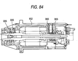
On the other hand, regarding a pipe structure for supply of
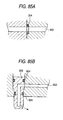
a fine quantity of lubricating oil, Fig. 84 shows a lubricating
apparatus of an oil-air type using an air flow as a medium. As
the state of connection of the end faces of two housings is shown
in Fig. 85A, a pipe passage 902 serving as an oil flow passage
formed in a housing is sealed by O-rings 904 which are disposed
on the housing end faces. Also, as the state of connection between
the nozzle frame 906 and pipe passage 902 is shown in Fig. 85B,
oil-air is supplied to the nozzle frame 106 through the pipe passage
902. However, in the case of a fine quantity of lubricating oil
being supplied, in a pipe arrangement structure using such O-rings
104, when the lubricating oil is jetted out, the volume of the
interior portion of the pipe passage is caused to vary due to the
elastic deformation of the O-rings 904, which makes it impossible
to supply a given quantity of lubricating oil.
Further, as a fine quantity oil lubricating method for
lubricating a spindle disposed in a machine tool, there are known
a lubricating method (which is hereinafter referred to as "a direct
jet lubricating method") for spraying a fine quantity of lubricating
oil directly into the interior portion of a bearing.
As an example of such a direct jet lubricating method, there
are known methods which are disclosed in JP-A-2000-74076 and
JP-A-2000-110711. In a lubricating structure which is disclosed
in JP-A-2000-74076, there is employed a pump which discharges
lubricating oil by means of the action of a pressurized operation
oil and an electromagnet. Also, in a lubricating apparatus
disclosed in JP-A-2000-110711, there is employed a fine quantity
lubricating pump which uses a super-magnetostrictive material.
However, the lubricating apparatus disclosed in
JP-A-2000-110711 just supplies the lubricating oil to a single
lubricating oil supply position. Thus, there is a problem about
how the superfine quantity of lubricating oil is supplied to each
of a plurality of bearings.
Further, in the case of the above-mentioned lubricating
apparatus of a direct jet lubricating type, a fine quantity of
the order of 0.001 ml of lubricating oil must be discharged at
a high speed. However, in the structures of both lubricating
apparatus disclosed in JP-A-2000-110711 and JP-A-2000-74076, the
high-speed discharge of a fine quantity of lubricating oil is realized
by a fine quantity lubricating pump using an electromagnet or a
giant-magnetostrictive material, which raises a problem that the
cost of the lubricating apparatus increases.
In the direct jet lubricating apparatus for jetting out a
fine quantity of lubricating oil at a high speed from a nozzle
directly into the bearing without using an air flow as a medium,
it is necessary that a fine quantity of lubricating oil to be outputted
from the lubricating apparatus is jetted out at a high speed from
a nozzle frame through a pipe. The pipe to be arranged from the
lubricating apparatus up to the nozzle frame must satisfy the required
condition that it is free from deformation against pressure because
a fine quantity of lubricating oil is fed through the pipe at a
high speed with high pressure. Therefore, in case where a part
easy to deform such as an O-ring is used in the joint portion,
there arises a problem that a proper discharge speed cannot be
maintained due to pressure loss. Especially, the lubricating
apparatus of a direct jet lubrication type has a major disadvantage
that it cannot be applied easily as a spindle lubricating apparatus
in a machine tool which requires the freedom of design.
SUMMARY OF THE INVENTION
The present invention aims at eliminating the drawbacks found
in the above-mentioned circumstances. Accordingly, it is a first
object of the invention to provide a spindle apparatus with a
lubricating device which injects a high-precision set fine quantity
of lubricant onto the lubricating surface of a rotary body at a
high speed to thereby minimize an increase in torque and bearing
temperature so as to be able not only to provide high torque stability
and reduce the generation of noises but also to reduce the size
and cost thereof, and a spindle apparatus using such lubricating
device.
In attaining the above first object, according to the invention,
there is provided a spindle apparatus comprising a shaft, at least
two bearings disposed spaced apart from the shaft in the axial
direction of the shaft, each of the bearings having an inner ring
fitted with the shaft, and a housing fitted with the outer rings
of the bearings, with the inner rings and outer rings of the bearings
being rotatable with respect to each other with rolling elements
between them, the spindle apparatus further including: a lubricating
device for supplying lubricating oil to the bearings at a discharge
speed in the range of 10 m/sec. - 100 m/sec. and in a fine discharge
oil quantity in the range of 0.0005 ml/shot - 0.01 ml/shot.
According to the above structure, since the discharge speed
of the lubricating oil to be discharged from the nozzle is high,
that is, 10 m/sec - 100 m/sec., the lubricating oil can be supplied
to the interior portion of the bearing positively without being
influenced by an air curtain which can occur in the high-speed
rotation. Also, because the discharge quantity of the lubricating
oil is fine, that is, in the range of 0.0005 ml/shot - 0.01 ml/shot,
an increase in the temperatures of the bearings can be controlled
down to a low level. Further, since there are not used attendant
devices including a high-pressure pump such as a jet type, there
is eliminated an increase in drag resistance which could be caused
due to an increase in the quantity of the oil supplied to the bearings,
so that, as a motor for driving the spindle, there can be used
a motor which is inexpensive and compact.
Also, in addition to the above structure, there may be disposed
a shaft rotation speed detector (tachometer) for detecting the
shaft rotation speed. In this case, by controlling the supply
interval and supply quantity of the lubricating oil discharged
from the lubricating device based on the detected results of the
shaft rotation speed detector (tachometer), a proper oil quantity
of lubrication is possible with respect to the spindle rotation
regardless of the spindle rotation speed, so that an ideal lubricating
condition can be always obtained in the interior portion of the
bearing. Also, the increase in the bearing temperature can also
be controlled down to a further lower level. Further, since the
lubricating oil is supplied to the interior portion of the bearing
positively, a lubricating oil supply efficiency can be enhanced
and the lubricating oil consumption can be reduced. Moreover,
since compressed air supplied by a compressor is not used as in
the lubricating device of an oil mist system or an oil-air system,
the noise level is low and the oil mist can be little produced.
And, in addition to the above structure, there may be disposed
a lubricating oil filter, an air bleed sensor, and a clogging detect
pressure sensor. In this case, there can be avoided troubles such
as a clogged condition.
Further, it is a second object of the invention to provide
a spindle apparatus which is capable of distributively supplying
a superfine quantity of lubricating oil from a single lubricating
device to a plurality of bearings stably, uniformly and positively.
In attaining the second object, according to the invention,
there is provided a spindle apparatus including: a spindle; a roller
bearing for supporting the spindle; a nozzle discharging the
lubricating oil to the roller bearing; and a multi-branch piping
device (a multi-distribution mechanism) between a superfine quantity
oil lubricating pump and the nozzle, for distributively supplying
lubricating oil from the superfine quantity oil lubricating pump
to the plurality of bearings, so that the lubricating oil is supplied
to each bearing from the multi-branch piping device.
With this structure, the lubricating oil supplied from the
superfine quantity oil lubricating pump is distributively supplied
to each bearing stably without reducing the discharge speed and
the discharge quantity, and without causing vibrations of the
discharge speed and the discharge quantity. Further, this structure
provides a supply of the lubricating oil for the spindle apparatus
having a plurality of bearings with only one lubricating apparatus.
That is, according to the present spindle lubricating apparatus,
thanks to the multi-distribution mechanism, not only a fine quantity
of lubricating oil can be distributively supplied to the plurality
of bearings at the discharge speed of 10 m/sec. - 100 m/sec. in
a discharge quantity of 0.0005 ml / shot - 0.01 ml / shot accurately
and stably, but also the structure of the spindle lubricating
apparatus can be made simple and compact. Therefore, an ideal
lubricating state can be always obtained in each of the bearings,
the stability of the bearing torque can be enhanced, and an increase
in the bearing temperature can be controlled down to a low level.
Also,the multi-distribution mechanism includes a distribution
housing having such a number of lubricating oil supply holes as
to corresponds to the number of distribution of the lubricating
oil, a rotor valve which can be rotatably contacted with the
distribution housing to thereby bring a flow passage into
communication with the lubricating oil supply holes sequentially,
and a motor for rotating the rotor valve.
More specifically, in the distribution housing, the lubricating
oil supply holes are disposed in a circular ring manner, and a
center flow passage is formed in the center of this circular ring.
The rotor valve has a groove serving as a flow passage in such
a manner that it extends from the center of rotation thereof up
to a diameter position larger than a pitch circle diameter (PCD)
at the positions of the lubricating oil supply holes.
According to this structure, in case where the rotor valve
is rotated, the center flow passage and lubricating oil supply
holes of the distribution housing are allowed to communicate with
each other by the groove of the rotor valve sequentially, so that
the lubricating oil can be supplied to the respective lubricating
oil supply holes.
Also, the distribution housing may also be structured such
that such a number of longitudinal holes as to corresponds to the
number of bearings (number of distributions) are formed in the
radial direction thereof and lubricating oil supply holes are formed
so as to extend from the thrust direction thereof as well as be
in phase with and penetrate through the longitudinal holes.
According to this structure, when the center flow passage
and lubricating oil supply holes of the distribution housing are
made to communicate with each other, the lubricating oil can be
supplied to the radial-direction longitudinal holes.
Further, the distribution housing may also be structured in
the following manner: that is, such a number of lubricating oil
supply holes as to corresponds to the number of bearings (number
of distributions) are formed such that they can be made to communicate
with the groove formed in the rotor valve from a direction oblique
with respect to the axial direction of the distribution housing.
According to this structure, since the lubricating oil supply
holes are formed in the oblique direction with respect to the axial
direction of the distribution housing, the projecting amount of
the distribution housing in the radial direction is reduced, thereby
being able to provide a structure which is excellent in space
efficiency.
And, the multi-distribution mechanism may also be composed
of a distribution housing having such a number of lubricating oil
supply holes as corresponds to the number of distributions, a rotor
valve which can be rotatably contacted with the distribution housing
to thereby bring a flow passage into communication with the
lubricating oil supply holes sequentially, a shaft for rotationally
driving the rotor valve, a spring member for energizing the shaft
toward the rotor valve side, and a thrust bearing for supporting
the shaft in a freely rotatable manner.
According to this structure, while reducing the rotation
resistance by the thrust bearing, the elastic compression force
of the spring member can prevent the lubricating oil from leaking
from the contact portions between the rotor valve and distribution
housing, so that the lubricating oil can be positively supplied
from the groove of the rotor valve to the lubricating oil supply
holes of the distribution housing.
By the way, the oil supply quantity to the interior portion
of the bearing, in case where dm•N is equal to or larger than 1000000,
preferably, may be in the range of 0.0005 cc/min. - 0.12 cc/min.,
and, more preferably, in the range of 0.003 cc/min. - 0.12 cc/min.
Also, the inside diameter of the nozzle outlet, preferably,
may be in the range of 0.08 mm - 0.6 mm and, more preferably, in
the range of 0.1 mm - 0.5 mm.
Further, a ratio of the length L (mm) of the pipe up to the
nozzle to the pipe diameter d (mm), preferably, may be 5 ≤ L/d4
≤ 12000 mm-3, and, more preferably, 5 ≤ L/d4 ≤ 10000 mm-3. To sum
up the above facts, by using the super fine quantity oil lubricating
system, a lubricating oil forced circulating device, a heat exchanger,
a lubricating oil collecting device, and other attendant devices
such as compressed air, which are used in the conventional lubricating
systems such as a lubricating system of an oil mist, a lubricating
system of an oil-air type and a lubricating system of a jet type,
can be simplified; the noise level can be controlled down to a
low level, which can be consideration for environment. And, the
consumption of the lubricating oil can be reduced, the bearing
torque can be enhanced in stability, and the bearing temperature
increase can be controlled down to a low level, thereby being able
to enhance the rotation accuracy of the spindle. Therefore,
according to the present invention, there can be provided a spindle
apparatus which is more advantageous than the conventional spindle
apparatus using the related lubricating methods.
Further, it is a third object of the invention to provide
a spindle apparatus with a lubricating apparatus which, when compared
with the lubricating apparatus using an electromagnet or a
giant-magnetostrictive material, is low in cost and is simple in
structure, does not generate the above-mentioned whizzing sounds,
can discharge a fine quantity of lubricating oil at a high speed,
and can enhance the freedom of design.
In attaining the above third object, according to the invention,
there is provided a lubricating apparatus for discharging a fine
quantity of lubricating oil from a nozzle directly to the interior
portion of a bearing at given time intervals at a high speed, including:
a pump having a larger discharge quantity than that from the nozzle;
and, a switch valve interposed between oil pipes for connecting
together the pump and nozzle and being structured such that, in
case where a discharge oil pressure from the pump is less than
a given pressure, it shuts off the oil pipes to thereby stop the
discharging of the lubricating oil from the nozzle, in case where
the discharge oil pressure from the pump is equal to or more than
the given pressure, it opens the oil pipes to thereby allow the
lubricating oil supplied from the pump to be discharged from the
nozzle for a given period of time, and it is capable of repeating
the execution of this series of operations.
According to the present lubricating apparatus, in case where
a discharge oil pressure from the pump is less than a given pressure,
the switch valve shuts off the oil pipes to thereby stop the discharging
of the lubricating oil from the nozzle and, on the other hand,
in case where the discharge oil pressure from the pump is equal
to or more than the given pressure, the switch valve opens the
oil pipes to thereby allow the lubricating oil supplied from the
pump to be discharged from the nozzle for a given period of time.
Therefore, without using an expensive fine quantity lubricating
pump using an electromagnet or a super magnetostrictive material,
a sufficient discharge speed can be obtained using an inexpensive
pump and thus, in a spindle which is rotated at a high speed, stable
lubricating characteristics, that is, enhanced seizure resistance
and reduced torque variations can be realized. Also, it is possible
to eliminate the generation of the whizzing noises of the rolling
bodies that raises a problem in the conventional oil-air and oil
mist lubricating methods. Further, in the portion of the pipe
that extends up to the switch valve, there can be used a resin-made
pressure resisting tube, which can enhance the design freedom of
the pipe arrangement.
And, in the lubricating apparatus, preferably, the discharge
quantity of lubricating oil to be discharged from the nozzle per
shot may be in the range of 0.0001 - 0.01 ml.
In the lubricating apparatus, since the discharge quantity
of lubricating oil to be discharged from the nozzle per shot is
set larger than 0.0001 ml, it is possible to prevent the lowered
flow speed of the lubricating oil which could be caused under the
great influence of the compression characteristic of the lubricating
oil, the pressure deformation of the pipes, and the response
characteristic of the switch valve; that is, a sufficient flow
speed can be obtained. Also, since the discharge quantity of
lubricating oil to be discharged from the nozzle per shot is set
smaller than 0.01 ml, torque variations occurring in the bearing
can be prevented.
Also, the discharge speed of the lubricating oil to be discharged
from the nozzle, preferably, may be set equal to or more than 10 %
of the peripheral speed of the inner ring of the bearing.
According to the thus structure, since the discharge speed
of the lubricating oil to be discharged from the nozzle is set
equal to or more than 10 % of the peripheral speed of the inner
ring of the bearing, there can be secured a discharge speed necessary
for the lubricating oil to reach the interior portion of the bearing.
As a practical advantage, the lubricating apparatus can use an
inexpensive oil pressure pump having a pump pressure of the order
of 2.5 MPa.
Further, the opening time of the switch valve may be preferably
set in the range of 0.1 - 50 ms.
With the above structure, a required discharge quantity of
0.0001 - 0.01 ml can be satisfied. That is, in case where the
pump pressure, lubricating oil and pipes are set according to the
following expressions, the relationship between the opening time
t of the switch valve and discharge quantity can be determined
and thus the opening time t of the switch valve, which is requested
to meet the required discharge quantity of 0.0001 - 0.01 ml, can
be set in the range of 0.1 - 50 ms.
v = Cd • (2 (p - Δp) / ρ)0.5
q = v • πd2 • t / 4
Δp = 32 • µ • L • d2 • v/D4
where, Cd expresses a flow coefficient, p: a pump pressure (Pa),
Δp: a pressure loss (Pa), ρ: a lubricating oil density (kg/m3),
d: a nozzle diameter (m), t: the opening time (s) of the switch
valve, µ: a lubricating oil viscosity coefficient (Pa • s), L: a
pipe length (m), and D: a pipe inside diameter (m), respectively.
Also, the lubricating apparatus may also be structured such
that the switch valve includes a fixed member having a fixed sliding
contact surface and a rotary member which has a movable sliding
contact surface to be closely contactable with the fixed sliding
contact surface and rotates the movable sliding contact surface
in sliding contact with the fixed sliding contact surface about
an axial line perpendicular to the fixed sliding contact surface.
In the fixed sliding contact surface of the fixed member, more
specifically, on the circumference of the fixed sliding contact
surface with the axial line as the center thereof, there are opened
up a discharge hole to be connected to the pump and an oil feed
hole to be connected to the nozzle. And, in the movable sliding
contact surface of the rotary member, more specifically, on the
circumference of the movable sliding contact surface with the axial
line as the center thereof, there is formed an arc-shaped slit
having a center angle larger than at least a center angle formed
between the discharge hole and oil feed hole.
According to the thus-structured lubricating apparatus, in
case where the rotary member of the switch valve is rotated with
respect to the fixed member thereof and the arc-shaped slit formed
in the movable sliding contact surface of the rotary member is
matched to the discharge hole and oil feed hole respectively formed
in the fixed sliding contact surface of the fixed member, the discharge
hole and oil feed hole are allowed to communicate with each other
through the arc-shaped slit. Therefore, only while the discharge
hole and oil feed hole are both matched to the arc-shaped slit
at the same time, the switch valve is opened (the oil pipes are
opened) , so that the lubricating oil from the pump can be discharged
from the nozzle for a given period of time.
Also, the lubricating apparatus may be structured such as
to have: a motor for rotating the rotary member; a pressure switch
for detecting the discharge oil pressure of the pump; and, a controller
which sends a drive signal to the pump, on receiving a detect signal
from the pressure switch issued when the discharge oil pressure
is equal to or more than a given pressure, sends a one-rotation
drive signal to the motor, after then, sends a drive stop signal
to the pump, and is capable of repeating the execution of this
series of operations at given time intervals.
According to the thus-structured lubricating apparatus, in
case where the pump is switched on by the controller, the oil pressure
is raised; and, in case where the controller detects through the
pressure switch that the oil pressure is equal to or higher than
a given pressure, the controller rotates the motor once and, after
then, the controller switched off the pump. This series of operations
are executed repeatedly at given time intervals by the controller,
whereby the lubricating oil from the pump can be discharged from
the nozzle at given time intervals.
Also, the lubricating apparatus may be structured as follows.
That is, the switch valve includes a fixed member having a fixed
sliding contact surface and a rotary member which has a movable
sliding contact surface closely contactable with the fixed sliding
contact surface and rotates the movable sliding contact surface.
in sliding contact with the fixed sliding contact surface about
an axial line perpendicular to the fixed sliding contact surface.
In the fixed sliding contact surface of the fixed member, more
specifically, on the circumference of the fixed sliding contact
surface with the axial line as the center thereof, there are opened
up a plurality of oil feed holes to be connected to the nozzle
and, at the position of the axial line, there is opened up a discharge
hole connected to the pump; and, in the movable sliding contact
surface of the rotary member, there is formed a slit in such a
manner that it extends from the axial line position along the radial
direction of the rotary member up to the position of the oil feed
hole.
According to the thus-structured lubricating apparatus, in
case where the rotary member of the switch valve is rotated with
respect to the fixed member thereof and the slit formed in the
movable sliding contact surface of the rotary member is matched
to the oil feed hole formed in the fixed sliding contact surface
of the fixed member, the switch valve is opened (the oil pipes
are opened), with the result that the lubricating oil from the
pump can be discharged from the nozzle for a given period of time.
In this case, since the plurality of oil feed holes are formed
on the circumference of the fixed sliding contact surface, each
time the rotary member is rotated, the lubricating oil from the
discharge hole is supplied to the respective oil feed holes, that
is, one rotation of the rotary member can supply the lubricating
oil to a plurality of portions.
And, the lubricating apparatus may be structured in the
following manner. That is, the switch valve includes a fixed member
having a fixed sliding contact surface and a slide member which
has a movable sliding contact surface closely contactable with
the fixed sliding contact surface and reciprocates the movable
sliding contact surface in the linear direction in sliding contact
with the fixed sliding contact surface with respect to the fixed
sliding contact surface. In the fixed sliding contact surface
of the fixed member, there are opened up a plurality of discharge
holes to be connected to the pump in such a manner that they are
spaced from each other in the linear direction; and, in the movable
sliding contact surface of the slide member, there are opened up
a plurality of oil feed holes to be connected to the nozzle in
such a manner that they are arranged in the linear direction at
the same intervals as the discharge holes.
According to the thus-structured lubricating apparatus, in
case where the fixed member and slide member are reciprocated in
the linear direction in sliding contact with each other and the
plurality of discharge holes formed in the fixed sliding contact
surface of the fixed member and the plurality of oil feed holes
formed in the movable sliding contact surface of the slide member
are allowed to communicate with each other or are shut off from
each other at the same time, the lubricating oil from the pump
can be discharged from the nozzle for a given period of time.
That is, according to this lubricating apparatus, since the slide
member is reciprocated in the linear direction in a sliding contact
manner, a movable member of a solenoid serving as a drive source
and a linear drive device such as a cylinder can be used as they
are.
Still further, the lubricating apparatus may be structured
in the following manner. That is, the switch valve includes: a
cylindrical-shaped stator having a fixed sliding contact surface
on the inner peripheral surface thereof; and, a rotor which has
a rotary sliding contact surface to be closely contacted with the
fixed sliding contact surface and rotates while the rotary sliding
contact surface is in sliding contact with the fixed sliding contact
surface. In the fixed sliding contact surface of the stator, there
are opened up a plurality of oil feed holes to be connected to
the nozzle in such a manner that they are spaced from each other
in the inner peripheral circle direction; and, in the rotary sliding
contact surface of the rotor, there are formed a plurality of discharge
holes to be connected to the pump in such a manner that they are
arranged in the outer peripheral circle direction at the same
intervals as the oil feed holes.
According to the thus-structured lubricating apparatus, in
case where the rotor is rotated within the stator and the plurality
of oil feed holes formed in the fixed sliding contact surface of
the stator are matched to the plurality of discharge holes formed
in the rotary sliding contact surface of the rotor, the lubricating
oil from the pump can be discharged from the nozzle for a given
period of time. The stator and rotor can be structured in a movable
fit manner, so that high-speed switching can be realized easily
using low torque. For example, a rotary solenoid using a permanent
magnet and an electromagnet can be used, a high-speed response
characteristic can be obtained, a drive circuit can be simplified
when compared with an ordinary motor, and the reduced cost of an
actuator can be realized.
Moreover, the spindle apparatus with the lubricating apparatus
according to the present invention may includes: a pump for switching
on and off the pressure of oil to be discharged to a hydraulic
main pipe; a discharge cylinder in which a discharge piston is
mounted, an oil supply chamber is formed on one end side of the
discharge piston in the moving direction thereof, and a hydraulic
chamber to be connected to the hydraulic main pipe is formed on
the other end side of the discharge piston, while the discharge
piston is disposed so as to be energized toward the hydraulic chamber
side by spring means; a three-way valve connected to the hydraulic
main pipe, an oil supply passage to be connected to the oil supply
chamber, and an oil storage passage, for allowing the hydraulic
main pipe and oil storage passage to communicate with each other
when the oil pressure is switched on and, on the other hand, when
the oil pressure is switched off and the oil pressure from the
oil storage passage is given to the three-way valve, for allowing
the oil storage passage and the oil supply passage to communicate
with each other; and, an oil storage cylinder in which an oil storage
piston is mounted and, on one end side of the oil storage piston
in the moving direction thereof, there is formed an oil storage
chamber to be connected to the oil storage passage, while the oil
storage piston is disposed so as to be engergized toward the oil
storage chamber side by spring means.
According to the present lubricating apparatus, since the
di scharge cylinder and oil storage cylinder are disposed separately,
when compared with the conventional lubricating apparatus in which
oil is stored within a cylinder disposed on one side end of a single
piston and the oil is discharged on the opposite side, the limits
on the dimensions of the seal member and return spring can be reduced,
which can facilitate the reduction of the diameters of the discharge
cylinder and oil storage cylinder. Also, due to provision of two
pistons, the oil operation area of the discharge piston can be
set larger than the oil pressurizing area, so that the discharge
piston can be pushed with a large force and thus a high-speed stroke
can be realized. As a result of this, when compared with a lubricating
apparatus using an electromagnet or a super magnetostrictive
material, a fine quantity of the order of 0.001 ml of oil can be
discharged at a high speed using a low-cost and simple structure.
And, the lubricating apparatus may also be characterized in
that, when the discharge port is closed and the oil pressure of
the hydraulic main pipe is on, the oil pressure of the oil supply
chamber becomes larger than the oil pressure of the hydraulic chamber.
According to the present lubricating apparatus, when the
discharge port is closed and the oil pressure of the hydraulic
main pipe is on, the oil pressure of the oil supply chamber becomes
larger than the oil pressure of the hydraulic chamber, thereby
being able to discharge oil at a high speed. That is, in the
conventional lubricating apparatus using a single piston, due to
the influence of the return spring for energizing the piston, the
oil discharge pressure is always lower than the oil supply pressure
because of the restitutive force of the return spring. However,
in the present lubricating apparatus, the oil pressure of the oil
supply chamber (that is, oil discharge pressure) can be increased,
with the result that discharging of oil at a high speed can be
realized.
Also, the lubricating apparatus may also be structured such
that, on the hydraulic chamber side of the discharge cylinder,
there is mounted a drive piston movable by the oil of the hydraulic
chamber to thereby push and drive the discharge piston, and the
oil operation area of the drive piston is larger than the oil
pressurizing area of the discharge piston.
According to the present lubricating apparatus, since the
oil operation area of the drive piston is larger than the oil
pressurizing area of the discharge piston, in case where the oil
pressure from the hydraulic main pipe is applied to the drive piston,
the discharge piston can be driven with a large force. Thanks
to this, the high-speed stroke of the discharge piston can be realized
and thus oil can be discharged from the discharge cylinder at a
high speed.
Further, the lubricating apparatus may also be structured
such that, between the discharge piston and drive piston, there
is formed an idling section where the drive piston can be moved
in a direction to approach the discharge piston.
According to the present lubricating apparatus, in case where
the oil pressure from the hydraulic main pipe is applied to the
drive piston, the drive piston is allowed to move the idling section
by itself with no contact with the discharge piston. That is,
without a start load which is otherwise generated in the start
time of the drive piston due to its contact with the discharge
piston, the drive piston is able to start under small movable
resistance. Thanks to this, while the drive piston is moving in
the idling section, the pressure of the oil pressure pump is raised
up to a sufficient level, and there is generated inertia in the
drive piston, so that the discharge piston can be driven with a
large and high-speed force.
And, the lubricating apparatus may also be structured such
that an umbrella valve is mounted in the three-way valve; and,
the umbrella valve is structured such that, when the oil pressure
is switched on, the main body of the umbrella valve closes the
oil supply passage and a flexible umbrella piece disposed on the
outer periphery of the umbrella valve main body is reduced in diameter
to thereby allow the hydraulic main pipe and oil storage passage
to communicate with each other and, on the other hand, when the
oil pressure is switched off and the umbrella valve receives the
oil pressure from the oil storage passage, the umbrella valve main
body is moved in a direction to open the oil supply passage and
the flexible umbrella piece is enlarged in diameter to thereby
allow only the oil storage passage and oil supply passage to
communicate with each other.
According to the present lubricating apparatus, in case where
the oil pressure of the hydraulic main pipe connected to the three-way
valve is switched on, the umbrella valve main body closes the oil
supply passage and the flexible umbrella piece disposed on the
outer periphery of the umbrella valve main body is reduced in diameter
due to the present oil pressure, thereby allowing the hydraulic
main pipe and oil storage passage to communicate with each other.
Therefore, oil from the hydraulic main pipe reaches the oil storage
cylinder through the oil storage passage, moves the oil storage
piston against the energizing force of spring means for energizing
the oil storage piston, and then flows into the oil storage chamber
of the oil storage cylinder. That is, storage of the oil into
the oil storage cylinder is completed. On the other hand, in case
where the oil pressure of the hydraulic main pipe is switched off,
the diameter reduced state of the flexible umbrella piece due to
the oil pressure is removed and thus the flexible umbrella piece
is enlarged in diameter, thereby shutting off the hydraulic main
pipe and oil storage passage from each other. At the same time,
due to the returning energizing force of the spring means for
energizing the oil storage piston, the umbrella valve main body
receives the oil pressure from the oil storage passage is thereby
moved in a direction to open the oil supply passage. As a result
of this, only the oil storage passage and oil supply passage are
allowed to communicate with each other and the oil stored in the
oil storage chamber is supplied through the oil storage passage
and oil supply passage and is filled into the oil supply chamber
of the discharge cylinder, thereby completing the preparation for
the next discharging operation.
Also, the lubricating apparatus may also be structured such
that, with the three-way valve, there is threadedly engaged an
air bleeding plug for moving the umbrella valve in a direction
to open the oil supply passage, or a stop plug in such a manner
it can be removed from the three-way valve.
According to the present lubricating apparatus, on the
three-way valve, there is disposed the air bleeding plug which
can move the umbrella valve in a direction to open the oil supply
passage. This air bleeding plug is used to deflate air within
the portion of the pipe existing upstream of the oil supply passage.
In order to be able to discharge a fine quantity of oil, it is
important that the air within the pipe can be deflated completely.
That is, in case where the oil discharge quantity is very small,
it is difficult to deflate the air within the pipe only by repeating
normal oil jets. Therefore, in case where the air bleeding plug
having a fine pin in the leading end thereof is threadedly engaged
with the three-way valve and oil when the oil pressure pump is
switched on due to the movement of the umbrella valve is forced
to flow into the oil supply passage, the air bleeding can be achieved
simply. After completion of the air bleeding, the air bleeding
plug is replaced with the stop plug and a normal operation is executed.
Also, the lubricating apparatus may also be structured such
that lubricating oil of 0.0005 - 0.01 ml per shot is directly jetted
to a rolling bearing at the discharge speed of 10% or more of the
peripheral speed of the inner ring of the rolling bearing.
According to the present lubricating apparatus, a quantity
of 0.0005 - 0.01 ml per shot of lubricating oil is directly jetted
to the rolling bearing at the discharge speed of 10% or more of
the inner ring peripheral speed of the rolling bearing. In
lubrication of the rolling bearing, the discharge speed necessary
for the lubricating oil to reach the interior portion of the bearing
is about 10% of the inner ring peripheral speed and, therefore,
the discharge speed provided by the present lubricating apparatus
is enough to lubricate the interior portion of the bearing.
Additionally, it is a second object of the invention to provide
a spindle apparatus including a pipe arrangement structure capable
of supplying a fine quantity of lubricating oil accurately and
stably even in case where the present spindle apparatus is applied
as a spindle apparatus for a machine tool which has a narrow and
limited space for pipe arrangement.
In attaining the second object, according to the present
invention, there is provided a spindle apparatus is structured
such that a pipe for supplying the lubricating oil is set such
that a pipe parameter (L • dn 2 / d4), which expresses the relationship
between the length L of the pipe, a nozzle diameter dn, and a pipe
inside diameter d, is smaller than 5 x 10⁴ [m-1], and also that,
the sum of the quantity of pipe expansion due to the pressure of
lubricating oil in the interior portion of the pipe and the compression
volume of the lubricating oil is equal to or less than the discharge
quantity of said lubricating oil.
According to the spindle apparatus of the invention, when
supplying a fine quantity of lubricating oil to the spindle apparatus,
the pipe for the lubricating oil is set so as to satisfy the given
conditions. Thanks to this, even when the present invention is
applied to a spindle apparatus which is narrow and limited in the
space for installation of a nozzle and arrangement of the pipe,
the nozzle and pipe can be disposed in a compact structure, so
that a fine quantity of lubricating oil can be supplied accurately
and stably and, at the same time, generation of noises due to the
whizzing sounds and poor lubrication due to the air curtain, which
have been problems to be solved in the conventional oil-air
lubricating apparatus, can be prevented.
In more detail, the present spindle apparatus is structured
such that, the nozzle frame for jetting out the lubricating oil
to the givenpositionsofthe interior portion of the spindle apparatus
and the lubricating apparatus are connected together by the pipe
which satisfies the following conditions:
where, d
n: nozzle diameter (0.08 x 10
-3 - 0.3 x 10
-3 [m])
K: bulk modulus [Pa] of lubricating oil
ν : Poisson's ratio of pipe material
p: average pressure [Pa] in pipe
q: discharge quantity [m
3].
Also, the present spindle apparatus is a spindle apparatus
having a cooling function using a jacket cooling system. In the
jacket cooling system, as a thermal displacement measure, cooling
oil is charged into an outer housing (outer cylinder) of a bearing
(outer cylinder cooling system).
According to the present spindle apparatus, even in the case
of a spindle apparatus of a jacket cooling system being narrow
and limited in the space for arrangement of a pipe for lubricating
oil and installation of a nozzle, a fine quantity of lubricating
oil can be supplied.
The present spindle apparatus may be structured such as to
include a spindle shaft, a plurality of rolling bearings for
supporting the spindle shaft in a freely rotatable manner, an inner
housing for covering the outside of the rolling bearings, and an
outer housing for covering the outside of the spindle apparatus;
and, a pipe is arranged so as to extend from the lubricating apparatus
up to a nozzle frame disposed within the inner housing through
a communication hole for supply of lubricating oil formed in the
outer housing along the axial direction thereof and also through
an opening formed in the inner housing.
And, the present spindle apparatus is also structured such
that the pipe is connected to the nozzle frame in the axial direction
of the housing.
According to the present spindle apparatus, even in a structure
which cannot provide a space for arrangement of a pipe in a direction
perpendicular to the axial direction of the housing, the pipe can
be installed by arranging the pipe in the axial direction of the
housing.
Also, the pipe may also be connected from the lubricating
apparatus to the nozzle frame through an opening formed in the
inside diameter surface of the outer housing.
In this case, even in a structure which cannot provide a
space for arrangement of a pipe in the axial direction of the spindle
shaft, the pipe can be installed by arranging it in a direction
perpendicular to the axial direction of the housing..
Further, in the present spindle apparatus, the inner housing
may includes a first inner housing to which the outer rings of
the rolling bearings are to be fixed, and a second inner housing
including an insertion portion for storing therein the first inner
housing in the axial direction thereof, while the inside diameter
of the inner peripheral surface of the insertion portion of the
second inner housing is set larger than the outside diameter of
the outer peripheral surface of the first inner housing.
According to this structure, when the first inner housing
is inserted into the second inner housing in the axial direction
thereof, since the pipe cannot be caught by and between them, the
first inner housing can be inserted smoothly. Thanks to this,
even in the deep and limited-space portion of the spindle apparatus,
the pipe can be arranged while the spindle apparatus is structured
so as to be easy to assemble.
Also, in case where a cut-out groove for arrangement of the
pipe is formed in the insertion portion of the second inner housing,
when the first housing is slid in the axial direction, the pipe
can be stored in the cut-out groove, so that the pipe can be inserted
smoothly.
BRIEF DESCRIPTION OF THE DRAWINGS
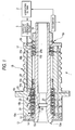
Fig. 1 is a section view of the internal structure of a spindle
apparatus according to a first embodiment of the invention;
Fig. 2 is a structure view of a lubricating unit employed
in the spindle apparatus;
Fig. 3 is a section view showing a super fine quantity lubricating
oil pump;
Fig. 4 is an enlarged view showing the angle and position
of a nozzle;
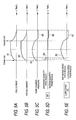
Fig. 5 a view of a time chart showing the time relationship
between currents to be applied to a coil and the discharge of
lubricating oil;
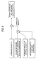
Fig. 6 is a block diagram showing a procedure for a discharge
quantity correction to be operated by a control device in order
to obtain a fixed discharge quantity;
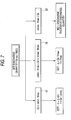
Fig. 7 is a block diagram of an example of a current control
function by discharge quantity;
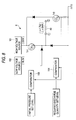
Fig. 8 is a circuit diagram of a coil control device employed
in a lubricating device;
Fig. 9 is an explanatory view showing coil current waveforms
in conjunction with the operation of a transistor;
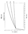
Fig. 10 is a graphical representation of an example of variations
in the coil current with respect to the lapse of time;
Fig. 11 is an explanatory view of the rising characteristic
of the coil current in abnormal and normal conditions;
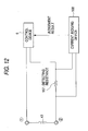
Fig. 12 is a view of a structure for detecting the coil current;
Fig. 13 is a block diagram of a schematic structure of a judging
device;
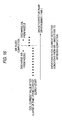
Fig. 14 is a time chart of the operation of the judging device;
Fig. 15 is an explanatory view of the rising characteristic
of the coil current in an air mixing condition and after an air
bleed completed condition;
Fig. 16 is a view of a coil current detect condition from
the air mixing condition to the air bleed completed condition;
Fig. 17 is a block diagram of a schematic structure of an
air bleed completion judging device;
Fig. 18 is a time chart of the operation of the air bleed
completion judging device;
Fig. 19 is a schematic view of an embodiment in testing the
performance of a super fine quantity oil lubricating pump;
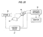
Fig. 20 is a schematic view of an embodiment of a visualizing
device used when testing the performance of a super fine quantity
oil lubricating pump;
Fig. 21 is a graphical representation of the relationship
between the discharge inside diameter of a nozzle outlet and discharge
speed from a nozzle;
Fig. 22 is a graphical representation of the relationship
between the parameter L/d4 of pipe resistance and the speed of
oil discharged;
Fig. 23 is a graphical representation of the relationship
between the parameter L/d4 of pipe resistance and the quantity
of oil discharged;
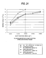
Fig. 24 is a graphical representation of the relationship
between the rotation speed of the spindle and the torque of the
bearing;
Fig. 25 is a graphical representation of the relationship
between the rotation speed of the spindle and increases in the
temperature in the outer race of the bearing;
Fig. 26 is a graphical representation of the results obtained
when the transitions of the bearing torque are checked;
Fig. 27 is a graphical representation of a comparison of noise
levels between a super fine quantity lubricating oil pump according
to the invention and a conventional device;
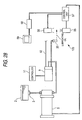
Fig. 28 is a schematic view of the superfine quantity lubricating
oil pump, showing a state in which the performance test of the
multi-branch piping device is executed;
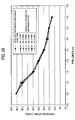
Fig. 29 is a graphical representation showing the comparison
results of the lubricating oil discharge speeds between a case
where the multi-branck piping device is used and a case where it
is not used;
Fig. 30 is a graphical representation showing the comparison
results of the lubricating oil discharge quantities between a case
where the multi-branch piping device is used and a case where it
is not used;
Fig. 31 is a section view of a super fine quantity lubricating
oil pump employed in a spindle apparatus according to a second
embodiment of the invention;
Fig. 32 is a schematic view showing a structure of a spindle
lubricating apparatus according to a third embodiment of the
invention;
Fig. 33 is a view of a specific structure of a spindle apparatus
shown in Fig. 32;
Fig. 34 is a section view showing the structure of a superfine
quantity oil lubricating apparatus with a multi-distribution
mechanism shown in Fig. 32;
Fig. 35 is an enlarged view of the structure of a
multi-distribution mechanism shown in Fig. 34;
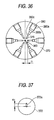
Fig. 36 is a section view taken along the arrow lines A-A
shown in Fig. 35;
Fig. 37 is a section view taken along the arrow lines B-B
shown in Fig. 35;
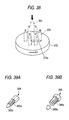
Fig. 38 is a typical view of a rotor valve, showing its operating
state;
Figs. 39A and 39B are perspective views of a pipe fixing joint;
Fig. 40 is a section view showing the structure of a superfine
quantity oil lubricating apparatus with a multi-distribution
mechanism according to a modification of the third embodiment;
Fig. 41 is an enlarged view of the structure of a
multi-distribution mechanism shown in Fig. 40;
Fig. 42A is a front view of a rotor valve shown in Fig. 41;
Fig. 42B is a section view of the rotor valve taken along
the arrow lines C-C shown in Fig. 42A;
Fig. 43 is a section view of the multi-distribution mechanism
taken along the arrow lines D-D shown in Fig. 41;
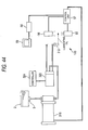
Fig. 44 is a schematic view of an embodiment of a test conducted
on the performance of the superfine quantity oil lubricating pump
according to the third embodiment;
Fig. 45 is a graphical representation of variations in the
oil discharging quantity with respect to the pipe length according
to the third embodiment;
Fig. 46 is a block diagram of the principles of a lubricating
apparatus according to a fourth embodiment of the invention;
Fig. 47 is a schematic view of the structure of a lubricating
apparatus according to a first example of the fourth embodiment;
Figs. 48A and 48B are plan views of the main portions of the
lubricating apparatus shown in Fig. 47;
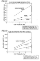
Fig. 49 is a graphical representation of the relationship
of the discharge speed with the pipe length with the nozzle diameter
as a parameter;
Fig. 50 is a graphical representation of the relationship
of the discharge quantity with respect to the pipe length with
the nozzle diameter as a parameter;
Fig. 51 is a graphical representation of the relationship
between the viscosity and the discharge speed with the nozzle diameter
as a parameter;
Fig. 52 is a graphical representation of the relationship
between the viscosity and the discharge quantity with the nozzle
diameter as a parameter;
Fig. 53 is a graphical representation of the relationship
between the pump pressure and the discharge speed with the nozzle
diameter as a parameter;
Fig. 54 is a graphical representation of the relationship
between the pump pressure and the discharge quantity with the nozzle
diameter as a parameter;
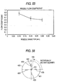
Fig. 55 is a graphical representation of the relationship
between the flow coefficient and the nozzle diameter found from
the measurement results shown in Figs. 49 - 54;
Fig. 56 is a plan view of the main portions of a lubricating
apparatus according to a second example of the fourth embodiment;
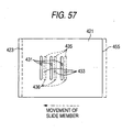
Fig. 57 is a plan view of the main portions of a lubricating
apparatus according to a modification of the second example of
the fourth embodiment;
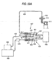
Fig. 58 is a plan view of a lubricating apparatus according
to a third example of the fourth embodiment, showing a state in
which it is applied to an actually used spindle;
Fig. 59A is a plan view of the structure of a lubricating
apparatus according to a fourth example of the fourth embodiment;
Fig. 59B is a plan view of the main portions of a switch valve
used in the fourth example of the fourth embodiment;
Fig. 60A and 60B are views showing a stator and a rotor of
a lubricating apparatus according to a modification of the fourth
example of the fourth embodiment;
Fig. 61 is a plan view of the structure of a lubricating apparatus
according to a fifth example of the fourth embodiment of the invention;
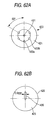
Figs. 62A and 62B are plan views of a fixed member and a rotary
member respectively forming a switch valve;
Fig. 63 is graphical representation of a speed instruction
to be outputted from a controller to a motor;
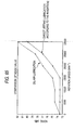
Figs. 64A and 64B are graphical representations of the results
of a test (temperature record chart) conducted on the rotation
in the fifth example of the fourth embodiment;
Fig. 65 is graphical representation of the results of measured
noises generated from a spindle apparatus according to a conventional
oil-air lubricating method and a spindle apparatus according to
the lubricating method employed in the fifth example of the fourth
embodiment;
Fig. 66 is a schematic view of the principles of a lubricating
apparatus according to a fifth embodiment of the invention;
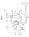
Fig. 67 is an explanatory view of the operation of the lubricating
apparatus shown in Fig. 66, showing a state thereof when an oil
pressure pump is on;
Fig. 68 is an explanatory view of the operation of the lubricating
apparatus shown in Fig. 66, showing a state thereof when an oil
pressure pump is off;
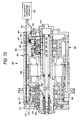
Fig. 69 is a schematic view of the structure of a lubricating
apparatus according to the fifth embodiment of the invention;
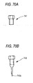
Fig. 70A is an explanatory view of a stop plug being a fitting;
Fig. 70B is an explanatory view of an air bleeding plug being
the fitting;
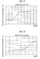
Fig. 71 is a graphical representation of the discharge piston
displacement quantity per unit time in a lubricating apparatus
including a drive piston having an idling section;
Fig. 72 is a graphical representation of the discharge piston
displacement quantity per unit time in a lubricating apparatus
including a drive piston having no idling section;
Fig. 73 is a schematic view of the structure of a spindle
apparatus according to a sixth embodiment of the invention;
Fig. 74 is a schematic view of the structure of a fine quantity
lubricating apparatus according to the sixth embodiment;
Fig. 75 is a section view of a nozzle frame according to the
sixth embodiment;
Fig. 76A is a perspective view of a joint formed of resin
material such as PEEK resin;
Fig. 76B is a perspective view of a joint formed of stainless
steel;
Fig. 77 is a perspective view of a tool for fixing a joint;
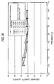
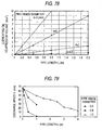
Fig. 78 is a graphical representation of the variations of
the lubricating oil compression volume with respect to the lengths
of pipes, while the relationship between them are plotted with
respect to various inside diameters of the pipes;
Fig. 79 is a graphical representation of the measured variations
of the discharge speed of lubricating oil with respect to the pipe
lengths, with the pipe inside diameters as a parameter;
Fig. 80 is a graphical representation of the results shown
in Fig. 79 with the pipe parameter L • dn 2 / d4 shown in the abscissas
axis thereof;
Fig. 81 is a graphical representation of the measured results
of the variations of the discharge speed v occurring when the Young's
modulus of the pipe is changed;
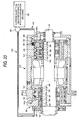
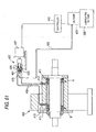
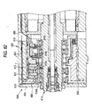
Fig. 82 is a partially enlarged section view of a spindle
apparatus according to a seventh embodiment of the invention;
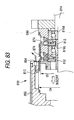
Fig. 83 is a section view of a housing according to the seventh
embodiment, showing the state of assembly thereof;
Fig. 84 is a schematic view of a conventional lubricating
apparatus of an oil-air type using an air flow as a medium; and,
Fig. 85A is a view explaining how the end faces of two housings
are connected together; and
Fig. 85B is a view explaining how a nozzle frame and the pipe
passages of the housings are connected together.
DETAILED DESCRIPTION OF THE PREFERRED EMBODIMENTS OF THE INVENTION
Now, a description will be given below in detail of the preferred
embodiments of a spindle apparatus according to the invention with
reference to the accompanying drawings.
(First Embodiment)
Figs. 1 and 2 show the structure of a spindle apparatus according
to a first embodiment of the invention. The spindle apparatus
1 comprises bearings for spindle 16a, 16b, 16c, 16d and 17 respectively
shown in Fig. 1 as well as a lubricating oil tank 2, a lubricating
oil filter 3, an air bleed device 4, a super fine quantity lubricating
oil pump 5, a control device 6 for controlling the super fine quantity
lubricating oil pump 5, a clogging sensor (a pressure sensor) 8,
a multi-branch piping device 9, and a pipe 10, respectively shown
in Fig. 2 and a tachometer 7 (see Fig. 1).
Fig. 1 is a longitudinal section view of the internal structure
of the spindle apparatus 1. As shown in Fig. 1, the spindle apparatus
1 comprises a plurality of angular ball bearings 16a, 16b, 16c
and 16d respectively used to support the front portion 15a of a
spindle 15 horizontally in a freely rotatable manner, a cylindrical
roller bearing 17 for supporting the rear portion 15b of the spindle
15, and a housing 18 for covering the respective outside portions
of these bearings 16a, 16b, 16c, 16d and 17. By the way, on a
front cover 12, there is mounted a cover 13.
Of the plurality of angular ball bearings, the outer ring
of the rear-most bearing 16d is secured to the inside diameter
stepped portion 18a of the housing 18, while the outer ring of
the front-most bearing 16a is secured to the front cover 12 through
an outer ring holder 14. Also, between the respective outer rings
of the angular ball bearings 16a, 16b, 16c and 16d, there are interposed
cylindrical-shaped outer ring spacers 21 respectively. In this
manner, the respective outer rings of the angular ball bearings
16a, 16b, 16c and 16d are fixed to the inner peripheral surface
of the housing 18.
Referring now to the inner rings of the angular ball bearings
16a, 16b, 16c and 16d, the front end of the inner ring of the front-most
bearing 16a is secured to the outside diameter stepped portion
15c of the spindle 15. Between the inner races of the angular
ball bearings 16a, 16b, 16c and 16d, there are interposed
cylindrical-shaped inner ring spacers 22 respectively, while the
rear end of the inner ring of the rear-most bearing 16d is secured
to a hold ring 23 fitted with the spindle 15 and is pressed forwardly
(in Fig. 1, to the left) in the axial direction thereof. The
respective inner rings of the angular ball bearings 16a, 16b, 16c
and 16d are fixed to the outside diameter surface of the spindle
15 in such a manner that they can be rotated integrally therewith.
By the way, although the spindle 15 in the present embodiment
is supported horizontally, for example, when it is used in a machining
center, it can be used in such a manner that it is supported vertically
or inclinedly.
The front end of the outer ring of the cylindrical roller
bearing 17 is secured to the inside diameter stepped portion 18b
of the housing 18 through the outer ring spacer 24a, while the
rear end of the outer ring is secured to a rear cover 26 and is
fixed to the inner peripheral surface of the housing 18. Also,
the front end of the inner ring is secured to the outside stepped
portion 15d of the spindle 15 through the inner ring spacer 24b,
while the rear end thereof is secured to a hold ring 27 fitted
with the spindle 15 and is pressed forwardly in the axial direction
thereof. The inner ring of the cylindrical roller bearing 17 is
fixed to the outside diameter surface of the spindle 15 in such
a manner that it can be rotated integrally therewith.
To the angular ball bearings 16a, 16b, 16c and 16d as well
as to the cylindrical roller bearing 17, there is supplied lubricating
oil from the super fine quantity oil lubricating pump 5 through
nozzles 20 which are respectively mounted within the housing 18.
The respective nozzles 20 are disposed in the interior portion
of the housing 18, and are fixed in such a manner that they are
inserted through mounting holes extending through the respective
outer race spacers 21 from the outside diameter surface. Also,
the leading ends of the respective nozzles 20 extend through the
outer ring spacers 21 and project into a clearance space formed
between the inner ring spacers 22 and inter-outer-ring seats 21.
In the present embodiment, there are disposed three nozzles 20
for each bearing. However, the number of nozzles 20 is not limited.
Next, description will be given below of the operation of
the spindle apparatus 1 with reference to Figs. 1 and 2.
Lubricating oil 25, which is filled into the lubricating oil
tank 2, flows through the lubricating oil filter 3 and the air
bleed device 4 into the super fine quantity oil lubricating pump
5. The super fine quantity oil lubricating pump 5 is controlled
by the control device 6 for an intermittent time adjustment, a
lubricating oil quantity adjustment, and a multi-branch piping
mechanism respectively for supply of the lubricating oil, so that
the super fine quantity oil lubricating pump 5 allows the multi-branch
piping device 9 to feed the lubricating oil 25 to the respective
pipes 10. Also, the number of pipes 10 is not limited to the number
of bearings. When the number of pipes is equal to the number of
bearings, the control device 6 is used to control the flow quantity
of the lubricating oil flowing into the individual pipes 10 and
the oil discharging intervals, thereby adjusting the quantity of
the lubricating oil to be supplied to the bearings. By the way,
in case where the lubricating oil is supplied to five pipes 10
in a quantity of 0.002 ml/shot at 2-second intervals from the super
fine quantity oil lubricating pump 5 to thereby lubricate five
bearings, the lubricating oil is supplied in a quantity of 0.002
ml to each of the five bearings at 10-second intervals.
Also, the quantity of the lubricating oil to be supplied to
the bearings and the oil supply intervals may also be changed for
every bearings and the lubricating oil may be supplied from some
or all of the pipes. Further, when the number of pipes is larger
than the number of bearings, the quantity of the lubricating oil
to be supplied to the bearings is set equal to the sum of the pipes
that are connected to the bearings. Also, when the number of pipes
is smaller than the number of bearings, the pipes are made to branch
from their intermediate portions and then the lubricating oil is
supplied to the bearings through the branching portions of the
pipes.
The lubricating oil 25, which is fed to the respective pipes
10, is positively supplied from the nozzles 20 into the interior
portions of the spindle bearings 16a, 16b, 16c, 16d, and 17. In
this case, the respective nozzles 20 are adjusted to the optimum
angles and positions, so that a proper quantity of the lubricating
oil 25 can be supplied into the interior portions of the bearings
for spindle 16a, 16b, 16c, 16d, and 17. Also, the intermittent
time adjustment and lubricating oil quantity adjustment are made
in accordance with the output of the tachometer 7 for detection
of the rotation speed of the spindle. By the way, the lubricating
oil quantity can also be adjusted using a flow sensor of a super
fine quantity type.
In supplying the lubricating oil, the lubricating oil filter
3 removes dust which gives rise to a clogged condition. However,
in case where dust is mixed into the lubricating oil for some reason
or other to thereby cause a clogged condition, that is, in case
where the lubricating oil is not supplied normally for some reason
or other to thereby cause an abnormal discharge, the clogging sensor
(pressure sensor) 8 is actuated to thereby avoid the occurrence
of a trouble. Also, in case where the air is mixed, the air bleed
device 4, which is formed of porous material, removes the mixed
air.
Next, description will be given below of the super fine quantity
oil lubricating pump 5.
Fig. 3 is a section view of the super fine quantity oil
lubricating pump 5. As shown in Fig. 3, there is disposed a rod
body 30 which is made of giant magnetostrictive material having
a positive characteristic, and one end portion 30a of the rod body
30 in the axial direction thereof is fixed to a case 32 through
a preload adjust mechanism 31. As the giant magnetostrictive
material of the rod body 30, for example, there can be suitably
used material having a trade name Terfenol-D manufactured by Edge
Technologies Co. (ETREMA division), or magnetostrictive material
manufactured by TDK Co. When a magnetic field is applied to the
rod body 30 by a coil (which will be discussed later) disposed
coaxially therewith, the rod body 30 is expanded in the axial direction
thereof due to a magnetostrictive phenomenon (Joule effect).
The preload adjust mechanism 31 may provide, for example,
a screw mechanism which, when it is rotated, can project in the
axial direction of the rod body 30 to press against one end portion
30a of the rod body 30. In the other end portion 30b of the rod
body 30 in the axial direction thereof, there is disposed a pressure
transmission member 34 which can energize the rod body 30 to the
preload adjust mechanism 31 side by a belleville spring 33 to transmit
the pressure without producing a clearance with respect to the
axial direction of the rod body 30, while the rod body 30 is connected
to a piston 35 through the pressure transmission member 34. The
piston 35 is slidably disposed in the interior portion of a cylinder
36. The cylinder 36 is formed in such a manner that the transverse
area S of its piston sliding space in a direction extending at
right angles to the axial direction thereof is set smaller than
the transverse area A of the rod body 30 in a direction extending
at right angles to the axial direction thereof; and, in the interior
portion of the cylinder 36, there is formed a pump chamber 37.
The cylinder 36 is connected through a pipe 38 to the clogging
sensor 8 (see Fig. 2). Here, although a check valve is not interposed
between the pump chamber 37 and clogging sensor 8, the check valve
may also be provided.
Also, in the cylinder 36, there is formed a suction port 39
which is used to suck the lubricating oil 25 into the pump chamber
37. In the suction port 39, there is disposed a suction valve
40; and, the suction valve 40 provides a check valve which prevents
the lubricating oil 25 from flowing externally of the pump chamber
37. Also, the flow passage sectional area Y of the suction valve
40 is set larger than the sectional area of the discharge opening
20a of the nozzle 20 enlargedly shown in Fig. 4, while the suction
port 39 is pipe-connected through a lubricating oil delivery pipe
41 to the lubricating oil tank 2. Therefore, the lubricating oil
25 can be delivered from the lubricating oil tank 2 to the pump
chamber 37 through the lubricating oil delivery pipe 41, whereas
the lubricating oil 25 is prevented from flowing reversely from
the pump chamber 37 to the lubricating oil tank 2.
On the outer periphery of the rod body 30, there is coaxially
disposed a coil 43 and, further, on the outer periphery of the
coil 43, there is disposed a yoke 44 which is formed of magnetic
material and forms a magnetic circuit in conjunction with the rod
body 30. The yoke 44, the base end of the cylinder 36 on the rod
body 30 side thereof, and part of the lubricating oil delivery
pipe 41 are stored in the interior portion of the case 32.
To the coil 43, there is electrically connected the control
device 6. The control device 6 outputs to the coil 43 a current
which is used to generate a magnetic field. Due to application
of this current to the coil 43, the rod body 30 receives the magnetic
field generated from the coil 43 and is thereby expanded, so that
the lubricating oil 25 within the pump chamber 37 is passed through
the pipe 38 and is discharged out from the nozzle 20.
Referring to the shape of the nozzle 20, as shown in Fig.
4, the discharge opening portion 20a of the nozzle 20 in the leading
end of the flow passage is formed in an inclined manner, so that
a pipe can be arranged even in a narrow space. In case where there
is room in the pipe installation space, the nozzle can be formed
in a straight manner and the pipe can be installed obliquely or
horizontally at an oil supply target position. Referring to the
lubrication in the interior portion of the bearing, since the oil
supply quantity is very fine, the oil supply target position is
important. As the oil supply target position, as shown in Fig.
4, the contact portion between the inner race and ball is preferred.
Thanks to this, a retainer and outer raceway surface can be lubricated
by the lubricating oil 25 which is allowed to flow outside due
to a centrifugal force generated with respect to the inner raceway
surface. For example, the diameter H of the oil supply target
position can be set such that H = (dc1 + Di1) /2. Here, dc1 expresses
the inside diameter of the retainer, and Di1 expresses the outside
diameter of the inner race. In this manner, by designing the angle
and position of the nozzle 20 optimally, the lubricating oil can
be accurately supplied at a desired position in the interior portion
of the bearing in a pin-spot supply manner.
Next, description will be given below of the operation of
the super fine quantity oil lubricating pump 5.
Fig. 5 shows a time chart representing the time relationship
between currents to be applied to the coil 43 and the discharge
of the lubricating oil, and Fig. 6 shows a block diagram displaying
the procedure for the discharge quantity correction to be operated
by the control device 6 in order to obtain a fixed quantity of
oil discharge.
In case where a current is output from the control device
6 to the coil 43 in accordance with a pattern (61) shown in (a)
of Fig. 5, the coil 43 generates a magnetic field to thereby expand
the rod body 30 formed of giant magnetostrictive material. Since
one end portion 30a side of the rod body 30 is fixed, the rod body
30 is expanded in the axial direction thereof on the other end
portion 30b side thereof; and, the piston 35 follows this expanding
operation and thus moves in a pattern (62) similar to a current
shown in (b) of Fig. 5.
As the piston 35 moves, the lubricating oil 25 within the
pump chamber 37 is compressed and, as shown in a pressure increase
pattern in (c) of Fig. 5, the pressure within the cylinder 36 is
increased. Due to such increase in the pressure, the suction valve
40 in the suction port 39 is closed so that the air accumulated
in the leading end portion of the nozzle 20 in the previous discharge
was discharged from the nozzle 20 in such a manner as shown by
a discharge pattern (64) in (d) of Fig. 5. After then, the lubricating
oil 25 is discharged out to the outside from the nozzle 20 at high
speed in such a discharge pattern (65) as shown in (e) of Fig.
5. And, in case where the current to the coil 43 becomes steady,
the expansion of the rod body 30 is caused to stop and the pressure
of the pump chamber 37 is lowered due to the discharge of the
lubricating oil 25.
After then, in case where the output of the current from the
control device 6 to the coil 43 is stopped, the expanded rod body
30 contracts so as to return back to its original condition, so
that the internal capacity of the pump chamber 37 is increased.
At the then time, as shown by a pressure pattern (66) in (c) of
Fig. 5, the pump chamber 37 becomes negative in pressure, with
the result that, as shown in a discharge pattern (67) in (e) of
Fig. 5, the lubricating oil 25 is supplied through the suction
valve 40 to the pump chamber 37. At the same time, as shown by
a discharge pattern (68) in (d) of Fig. 5, a slight quantity of
air also flows in from the leading end of the nozzle.
The flow-in quantity of this air is sufficiently small when
compared with the supply quantity of the lubricating oil 25.
Referring further to the flow-in quantity of the lubricating oil
25 and the flow-in quantity of the air, because the sectional area
of the nozzle flow passage in a direction at right angles to the
axial direction of the nozzle is sufficiently smaller than the
sectional area of the suction valve flow passage in a direction
at right angles to the axial direction of the suction valve 40,
and also because the suction valve 40 is situated closer to the
piston 35 than the nozzle 20, the negative pressure transmission
time is shortened, with the result that the quantityof the lubricating
oil from the suction valve 40 becomes larger than the flow-in quantity
of the air. Therefore, in the next discharge operation time as
well, similarly, the lubricating oil discharge is possible.
Preferably, the volume of the nozzle hole of the nozzle 20
may be equal to or greater than the volume of the air flowing from
the nozzle hole in the above-mentioned suction step. The reason
for this is as follows: that is, because the resistance of the
air when the air passes through the nozzle hole is smaller than
the resistance of the lubricating oil 25 when it passes through
nozzle hole, in case where the nozzle hole is completely filled
with the air, the fluid resistance of the nozzle hole is smaller
than that of the suction side check valve, which raises a fear
that the lubricating oil 25 is difficult to be sucked in from the
suction side check valve.
There may also be interposed a check valve between the pump
chamber 37 and the discharge side pipe. By the way, in this case
as well, due to delay in the response of the discharge side check
valve as well as due to the closing operation of the valve, a slight
quantity of air flows in through the nozzle hole; that is, it can
be expected to avoid a fear that the lubricating oil 25 can drip
down from the leading end of the nozzle, but the oil dripping preventive
effect is lowered.
Now, since there are present the flow-in of the air from the
nozzle 20 when the rod body 30 is contracted, a decrease in the
volume of the lubricating oil 25 caused by the compression of the
lubricating oil 25 within the internal capacity between the suction
valve 40 and the exit of the nozzle, and an increase in the internal
capacity caused by the pressure deformation of parts defining the
internal capacity such as a cylinder and a pipe, although they
are respectively very small in quantity. In order to be able to
discharge the lubricating oil 25 in a desired quantity from the
nozzle 20 with accuracy, it is necessary to set the discharge quantity
with these variable elements taken into account.
In view of this, the super fine quantity oil lubricating pump
5 according to the present embodiment is characterized in that
a current is applied to the coil 43 from the control device 6 with
these variable elements taken into account. That is, in the present
embodiment, as shown in Fig. 6, "the volume decrease quantity of
the lubricating oil when compressed", "increase in the internal
capacity", and "air suction quantity when the rod body is contracted"
are regarded as main variable elements; and, the current is set
with these variable elements taken into account. The variable
elements may further include other elements such as the temperature
of the lubricatingoil 25 and the viscous resistance of the lubricating
oil 25.
A decrease in the capacity of the pump chamber 37 caused when
the rod body 30 is expanded, as shown in an equation (1), is equal
to the sum of the quantity of the air flowing in from the nozzle
20 when the rod body 30 is compressed, the volume decrease quantity
of the lubricating oil 25 within the internal capacity between
the suction valve 40 and nozzle exit when the lubricating oil 25
is compressed, an increase in the internal capacity due to the
pressure deformation of the parts defining the internal capacity,
and a required discharge quantity of the lubricating oil 25 to
be discharged from the nozzle 20.
Decrease in the capacity of the pump chamber 37 (piston cross
sectional area x piston movement length)
= (quantity of the air flowing in from the nozzle when
the rod body is contracted)
+ (volume decrease quantity of the lubricating oil due
to high pressure)
+ (increase in the internal capacity due to high
pressure)
+ (required discharge quantity Qrf)
By controlling the current to be applied to the coil 43 in
such a manner as to satisfy the equation (1), a very small quantity,
that is, of the order of 0.0005 - 0.01 ml of the lubricating oil
25 can be discharged out intermittently at the high speeds of approx.
10m/sec. - 100m/sec.
By the way, as the values of the respective items in the equation
(1), the measured or set values can be used depending on a spindle
apparatus used.
The discharge quantity of the lubricating oil 25 can be found
according to an equation (2).
Qr = Δ f
Here, Qr[ml/sec.] expresses a required discharge quantity
(a set discharge quantity), Δ[ml/shot] expresses a discharge
quantity per operation when a rated current is supplied, and
f [shot/sec.] expresses an operation frequency (a supply frequency)
to be applied to the coil 43.
The set discharge quantity Qr is classified to three conditions
shown in Fig. 7 according to the value thereof, then can be controlled
as follows.
At first, in case where the set discharge quantity Qr is equal
to or smaller than a discharge quantity when the minimum shot is
carried out at the highest operation frequency, that is, in the
case of (51) where Qr ≤ Δmin • fmax, a discharge quantity Δ per
operation and an operation frequency f are respectively set in
the following manner:
That is,
Δ = Δmin, f = Qr / Δmin.
Here, Δ min (ml/shot] expresses the minimum discharge quantity
per operation at the minimum current that can be controlled, in
the present embodiment, it is set as 0.001 [ml/shot]. Also,
fmax[shot/sec.] expresses the highest operation frequency that
can be output in the present apparatus.
Therefore, a final set discharge quantity (a required discharge
quantity) Qrf in this case is set according to an equation (3).
Qrf = Δmin x (Qr / Δmin)
Also, in the case of (52) where a set discharge quantity Qr
is Δmin • fmax < Qr ≤ Δmax • fmax (here, Δ max[ml/shot] is the
maximum discharge quantity per operation at the controllable maximum
current), a discharge quantity Δ per operation and an operation
frequency f in a position operation are respectively set in the
following manner:
That is, Δ = Qr / fmax, f = fmax.
Therefore, a final set discharge quantity (a required discharge
quantity) Qrf in this case is set according to an equation (4).
That is,
Qrf = (Qr/fmax) x fmax
And, in the case of (53) where a set discharge quantity Or
is set such that Δmax • fmax < Qr, since this quantity is exceeds
the discharge ability of the present apparatus, a discharge
disapproval signal is output from the control device 6 (see Fig.
6).
As a result, according to the above-mentioned super fine
quantity oil lubricating pump 5, there can be provided the following
effects.
That is, in the contracted condition of the rod body 30, since
the air flows in from the nozzle 20 and the leading end of the
liquid surface of the lubricating oil is thereby moved to the interior
portion of the nozzle, the lubricating oil can be prevented from
dripping down when the present pump is out of operation.
Also, in the expanded condition of the rod body 30, during
the time when the air in the leading end of the nozzle is pushed
out, the pressure of the lubricating oil 25 within the cylinder
36 is increased. For this reason, there is produced a slight delay
in the time necessary for the lubricating oil 25 to be discharged
from the nozzle end. However, this delay time is cancelled by
the time necessary for the lubricating oil 25 to be increased up
to a given pressure. As a result of this, at the discharge time
of the lubricating oil 25, there can be obtained a high discharge
speed which is close to a given speed, which makes it possible
to reduce a possibility that the lubricating oil 25 can be discharged
at a speed less than the given speed.
Further, since the cross sectional area S of the cylinder
36 in a direction at right angles to the axial direction thereof
is set smaller than the cross sectional area A of the rod body
30, the pressure of the lubricating oil 25 within the cylinder
can be made higher than the pressure generated in the rod body
30 itself, which makes it possible to discharge the lubricating
oil 25 at a higher pressure.
And, by bringing the lubricating oil 25 into direct contact
with the surface to be lubricated, there is eliminated the need
for provision of an air pump which is used to deliver the lubricating
oil 25.
Also, when increasing the pressure of the lubricating oil
25 within the cylinder up to a high pressure, the compression of
the lubricating oil 25 and the expansion of the cylinder 36 cannot
be neglected; however, because the current to be applied to the
coil 43 is corrected by these variable elements, a desired discharge
quantity can be obtained with high accuracy.
Further, since the coil current is controlled to thereby be
able to adjust the lubricating surface contact quantity of the
lubricating oil 25 easily, there is no need for provision of a
fixed quantity valve. This makes it possible to realize a lubricating
device which is simple in structure and compact in size.
Also, the control device 6 may also be a device which detects
the rotation speed of a rotary body to be lubricated, and supplies
to the coil 43 a current having a current value corresponding to
the detect signal and/or a current supply frequency corresponding
to the detect signal, thereby adjusting a lubricating oil discharge
quantity. In this case, the lubricating oil 25 can be supplied
in the optimum quantity that can vary according to the rotation
speed of the rotary body. This not only can prevent the excessive
supply of the lubricating oil 25 but also can always provide the
optimum lubricating effect.
For example, the rotation speed of a shaft (a rotary body)
of a bearing, to which the lubricating oil is to be supplied, is
detected by an encoder, and the thus obtained rotation speed is
input to the control device 6. The control device 6 outputs a
coil current while adjusting the current value and operation
frequency of a drive current to be applied to the coil 43 in such
a manner that, when the rotation speed is high, the lubricating
oil 25 can be supplied in a large quantity and, for the slow rotation
speed, the lubricating oil 25 can be supplied in a small quantity.
Now, Fig. 8 shows the circuit configuration of the coil control
device employed in the lubricating device according to the present
embodiment. The control device 6 according to the present embodiment
is connected to the coil 43 which is used to expand the rod body
30 made of the giant magnetostrictive element shown in Fig. 3,
and controls the application of a current to the coil 43.
As shown in Fig. 8, the control device 6 comprises a high
voltage source 161 for causing an applying current to rise suddenly,
a lowvoltage source 162 for obtaining a required lubricant discharge
quantity after the rise of the applied current, and two transistors
(FET) Tr1 and Tr2 which are respectively used to switch these voltage
sources 161 and 162 according to the outputs of two comparators
163 and 164.
Referring now to the operation of the control device 6, in
case where Tr1 and Tr2 are both firstly turned on, a current is
supplied to the coil by the high voltage source 161 and low-voltage
source 162. At the then time, as shown by a current waveform in
Fig. 9, the coil current rises suddenly up to an initial pressure
set level (a first current value). The rising characteristic of
the coil current is shown by an equation (5).
I (t) = E/r [1-exp {-rt/L}]
where, I: current, E: voltage, r: resistance, and L: inductance.
For example, assuming that the coil resistance r is 1.7 [Ω],
the inductance L is 5 [mH] and the voltage is 200 [V], the current
I(t) reaches 5 [A] with the passage time t of 128 [µ s] according
to the above equation.
As shown in Fig. 9, in case where 5 [A] is set as the initial
pressure set level, the control device 6 detects that the current
reaches 5 [A] and thus the control device 6 turns off Tr1. In
response to this, the current is supplied to the coil only from
the low voltage source side thereof. The then voltage E of the
low voltage source can be found in the following manner.
If the sectional area of the nozzle is expressed as Sn [mm2],
the cross sectional area of the cylinder internal capacity is
expressed as Sc [mm2] and the expansion of the giant magnetostrictive
element is expressed as ΔL [mm/A], then the expansion speed vm
[mm/s] of the giant magnetostrictive element necessary to obtain
a required discharge speed v [mm/s] can be expressed by an equation
(6).
vm = v • Sn/Sc
Also, the required increase speed I' [A/s] of the current
can be expressed by an equation (7).
I' = vm / ΔL
For example, assuming that the sectional area Sn of the nozzle
is 0.008 [mm2], a required discharge speed v is 50000 [mm/s], and
the cross sectional area Sc of the cylinder internal capacity is
30 [mm2], the required expansion speed vm of the giant
magnetostrictive element is 13.3 [mm/s].
At the then time, assuming that the expansion ΔL of the giant
magnetostrictive element is 0.01 [mm/A], the required increase
speed ΔI of the current is 1330 [A/s].
Also, assuming that the discharge quantity is 1 [mm
3], the
required current increase ΔI can be obtained in the following manner: that is,
A required time T necessary to reach this current value can also
be obtained in the following manner: that is,
If the above respective parameters are substituted into the
equation (5), then the voltage E is 18.3 [V]. Therefore, under
the above condition, this voltage E may be set as the voltage value
of the low voltage source 162.
In this manner, by setting the voltage of the low voltage
source as a voltage value to be determined according to the discharge
speed, there can be obtained a desired discharge speed in a given
pump. And, when the time T passes after the current value reaches
an initial stress set level, that is, when a desired discharge
quantity is obtained, Tr2 is also turned off to thereby cut the
coil current. In case where the generation of the coil current
due to the on and off operations of Tr1 and Tr2 is achieved at
a given operation frequency, the lubricant can be discharged
intermittently from the lubricating device.
According to the present system, when compared with a dropper
system in which a current is controlled by feeding back the current,
and a pulse width control system, the circuit of the control device
can be configured in such a manner that power can be saved and
the cost thereof can be reduced.
By the way, the circuit according to the present embodiment
is a circuit in which the voltage value can be switched and turned
off automatically according to the current value of the coil.
However, the voltage value may also be switched and turned off
by a timer.
Also, in Fig. 9, the current is turned off after the current
value reaches a required discharge quantity level. In this case,
preferably, the current value may be lowered little by little in
order to prevent cavitation from occurring within the pump chamber.
Now, Fig. 10 is a graphical representation of an example of
variations in the coil current with respect to the elapsed time.
By the way, in this case as well, the inductance L of the coil
is 5 [mH] and the resistance r is 1.7 [Ω].
As shown in Fig. 9, by turning on both of Tr1 and Tr2 of the
control device 6 to thereby apply a high voltage, the coil current
is caused to rise suddenly.
Next, Tr1 is turned off to thereby discharge the lubricant
at a given discharge speed only by the low voltage source. In
Fig. 10, the voltage values of the low voltage source is shown
in three kinds, that is, 24 [V], 18 [V], and 12 [V]; and, the voltage
E in the above-mentioned calculation example, which is 18.3 [V],
is almost equal to the present calculation example which is 18
[V].
Also, the lubricating device according to the present
embodiment is structured in such a manner that it can detect a
trouble such as lubricant leakage or a clogged condition to thereby
monitor the operating condition of the pump.
At first, description will be given below of the properties
of the magnetostrictive element. As the typical properties of
the magnetostrictive element, there can be given the following
two properties.
One of them is a property which is referred to as a Joule
effect due to which the magnetostrictive element can be distorted
by a magnetic field acting on the magnetostrictive element. As
described above, the magnetostrictive pump is structured such that
it applies a magnetic field to a magnetostrictive element using
this property to thereby expand the magnetostrictive element so
as to be able to drive a piston.
The other is a property which is referred to as a Villari
effect. The Villari effect is an effect in which the permeability
of a magnetostrictive element is changed according to stresses
applied to the magnetostrictive element. When a coil for driving
is disposed in a magnetostrictive element, the inductance of the
coil can be varied due to the Villari effect. Generally, in giant
magnetostrictive material, in case where the stress increases up
to about 1 [MPa], the inductance decreases about 30% with respect
to the inductance when the stress is zero.
Trouble detection is possible by using this Villari effect
in the following manner. That is, assuming that when a lubricating
device is in normal operation, the pressure within a cylinder is,
for example, about 4 [MPa] and the cross sectional area of a piston
is 1/4 of the cross sectional area of a giant magnetostrictive
element, the stress of the giant magnetostrictive element is about
1 [MPa]. In this case, the decrease rate of the inductance of
the coil including the giant magnetostrictive element is equal
to a decrease rate corresponding to the present stress, that is,
about 30%.
Here, in case where a trouble occurs in the lubricating device
and the nozzle is thereby clogged, the pressure within the cylinder
increases up to a high pressure in the range of 30 - 40 [MPa],
and the stress of the giant magnetostrictive element also increases
correspondingly to this cylinder pressure, with the result that
the decrease rate of the inductance of the coil is about 40%.
On the other hand, in case where lubricant leakage occurs within
the giant magnetostrictive material pump, the pressure within the
cylinder and the stress of the giant magnetostrictive element are
both almost zero, and the decrease rate of the inductance of the
coil is also almost zero.
In this manner, in case where any trouble occurs in the operating
condition of the giant magnetostrictive material pump of the
lubricating device, the decrease rate of the inductance of the
coil varies greatly from 0% to 40%.
By the way, the rising characteristic of a current flowing
in a coil, as described above, can be expressed by the equation
(5).
According to the equation (5), as shown in Fig. 11, when the
decrease in the inductance of the coil is small, a current I flowing
in the coil rises later than a design value; and, on the other
hand, when the decrease in the inductance of the coil is large,
the current I rises earlier than the design value.
In this manner, by detecting the rising time of the current
flowing in the coil, the decrease rate of the inductance of the
coil, that is, the stress of the giant magnetostrictive element
can be detected.
Thanks to the rising characteristic of the current, as shown
in Fig. 12, by monitoring a current flowing in the coil 43 using
a detecting resistance 167 and a current judging device 168, it
is possible to judge whether the operating condition of the giant
magnetostrictive material pump is good or not. The detecting
resistance 167 and current judging device 168 respectively
correspond to a current measuring device and a trouble judging
device.
That is, in case where the rising time of the current flowing
in the coil 43 is almost equal to the design value, it can be found
that the giant magnetostrictive material pump is operating properly.
In case where the rising time of the current is earlier than the
design value, it can be found that the pressure within the cylinder
36 is caused to increase, for example, due to the clogged condition
of the nozzle 20 and a great stress has been generated in the giant
magnetostrictive element. Also, in case where the rising time
of the current is later than the design value, it can be found
that there has occurred a trouble such as the leakage of the lubricant
form the lubricant flow passage and only a small stress has been
generated in the giant magnetostrictive element.
Now, Fig. 13 is a block diagram of the schematic structure
of the judging device 168, and Fig. 14 is a time chart showing
pulse signals respectively generated in correspondence to discharge
intervals as well as sensor outputs in steady and abnormal operations
of the lubricating device. In this case, signals in the time when
the lubricating device is in the discharging condition and detect
signals are different in the normal and abnormal conditions, that
is, signals in the time corresponding to the pulse issuing time
ta shown in Fig. 14 are detected.
When detecting the abnormal condition occurrence during the
steady operation of the lubricating device, at first, whether the
present operating condition is in an air bleed condition in the
start stage or not is judged by comparing the cycle number and
stroke of the piston 35 with their respective set values. When
it is found that the present operating condition is not in the
start stage, the output of the coil current is compared with a
set value 1 which is a set value for the normal operation. In
case where the output of the coil current falls within the range
of the lower to upper limits of the set value 1, the current operation
continues on as it is; and, on the other hand, in case where it
is out of the range of the set value 1, the judging device 168
issues a stop signal for stopping the operation of the lubricating
device. Due to this, the detection of the abnormal condition
occurrence in the steady operation and the stop of the lubricating
device are possible.
A pulse generator 140 shown in Fig. 13 links a signal for
controlling the intermittent operation of the lubricating device
with the judging device 168, or links such signal with a timer
built in the judging device 168 or a separately provided timer
to thereby be able to monitor an output signal from a sensor
corresponding to the pulse issuing time ta shown in Fig. 14. Also,
as the judging device 168, there can be used not only the lubricating
device but also a computer which controls the operation of a machine
in which the lubricating device is used.
As described above, since there is a close relationship between
the pressure of the interior portion of the cylinder 36 and the
discharge of the lubricant from the nozzle 20, when the rising
of the current of the coil 43 is shifted from the designed target
value, it is supposed that the discharge of the lubricant from
the nozzle 20 is also out of order.
Here, referring to an example where the lubricating device
according to the invention is used as a device for supplying the
lubricant to the rolling bearing of a high-speed spindle, when
it is detected that the rising characteristic of the coil current
is shifted from the target value, the current judging device 168
is allowed to issue an abnormal signal to thereby be able to enforce
a feedback control, for example, to stop the rotation of the high-speed
spindle urgently.
Also, the present embodiment is structured such that completion
of air bleed from the nozzle can be detected.
As described before, thanks to the Villari effect that is
one of the main properties of a magnetostrictive element, with
respect to the inductance when a stress given to a giant
magnetostrictive element is zero, the inductance when the stress
is 1 [MPa] decreases about 30%.
Due to the above relationship, the quickness of the rising
of a current flowing in a coil shown in Fig. 15 is connected with
a stress which a giant magnetostrictive element receives, that
is, is connected with the pressure in the interior portion of a
cylinder. Therefore, by detecting a current flowing in a coil
as shown in Fig. 16 using the detecting resistance 167 and current
judging device 168 (which respectively correspond to a current
measuring device and an air mixture judging device) shown in Fig.
12, completion of air bleed of a giant magnetostrictive material
pump can be judged.
In other words, when detecting the air bleed completion in
the start time of the operation of the lubricating device, when
the rising characteristic of the current is compared with the
characteristic of the current in the normal state thereof, in case
where the current rising time is longer than a given steady time,
that is, when the current value after the time t is small, it is
judged that the air remains within the cylinder 36 and within the
lubricant flow passage. When the air remains still, in order to
remove the air in a short time, the giant magnetostrictive material
pump is operated by the control device 6 shown in Fig. 3 in such
a manner that the piston 36 can be driven at a faster cycle than
the steady state thereof as well as with a large stroke. After
then, when the air bleed is completed, that is, when the current
value becomes the steady value, the giant magnetostrictive material
pump is returned back to its steady state operation.
Due to this, for example, when the lubricating device is operated
for the first time or when the operation of the lubricating device
is started in the morning, the air bleed canbe automatically completed
in a short time.
Now, Fig. 17 is a block diagram of the schematic structure
of the judging device 168 which is used to judge the air bleed
completion, and Fig. 18 is a time chart pulse signals to be generated
correspondingly to discharge intervals as well as sensor outputs
in the air mixing time and in the air bleed completion time when
the lubricating device is started. In this case, the judging device
168 detects a signal which corresponds to the time when not only
the lubricating device is in the discharge state but also there
is a difference in a detect signal between the normal state and
the air mixed state, that is, a signal which corresponds to the
pulse issuing time ta shown Fig. 18. Similarly to the above, in
case of detecting the completion of air bleed, whether the present
operating state is the air bleed state in the start time of the
lubricating device or not is judged by comparing the number of
cycles and strokes of the piston 35 with their respective set values.
When the operating state is the start time, the output of the
pressure sensor is compared with the set value 2 that is a set
value in the normal state. In case where the output of the pressure
sensor is smaller than the set value 2 and out of the set range,
the current operation is allowed to continue on. On the other
hand, in case where it is equal to or larger than the set value
2, there is generated a signal which shows that the operation is
in the steady state.
In this manner, whether the air bleed is completed or not
can be detected as well as the cycle number and stroke of the piston
5 can be switched to the steady operating state.
A pulse generator 140 shown in Fig. 17 links a signal for
controlling the intermittent operation of the lubricating device
with the judging device 168, or links such signal with a timer
built in the judging device 168 or a separately provided timer
to thereby be able to monitor an output signal from a sensor
corresponding to the pulse issuing time ta shown in Fig. 18. Also,
as the judging device 168, there can be used not only the present
lubricating device but also a computer which controls the operation
of a machine in which the lubricating device is used.
Next, description will be given below of a performance test
conducted on the super fine quantity oil lubricating pump 5.
Figs. 19 and 2 0 are respectively schematic views of an embodiment
in which the performance of the super fine quantity oil lubricating
pump 5 was conducted. Here, description will be given of the results
obtained by checking the influence of an air curtain on the nozzle
20 in the high-speed rotation of the spindle when the discharge
state of the lubricating oil 25 was visualized by a CCD camera
56 and videotape recorded, the relationship of the pipe inside
diameter and length with the discharge speed, and the relationship
between the pipe inside diameter and discharge oil quantity,
respectively. By the way, as the pipe material, there are used
metal such as austenite stainless steel SUS 316, and plastics such
as PEEK (polyether-ether-keton). However, there can also be used
other material such as ordinary iron/steel material,
aluminium/copper non-metallic material, plastic material, and
ceramic material.
The present performance test was conducted under a severer
condition (that is, under a condition that is easy to be influenced
by the air curtain) by setting the distance between the nozzle
leading end and the bearing as about 50 mm which is much longer
than the normal distance (about 10 mm).
Supply of the lubricating oil to the interior portion of the
bearing was set such that the lubricating oil can lubricate the
contact portion between the inner race and rolling elements, while
the lubricating oil supply state was visualized and was videotape
recorded. A visualizing apparatus is composed of a strobe 55,
a CCD camera 56, a control device 57 for controlling the strobe
55 and CCD camera 56, a videotape recorder 58 for recording video
signals from the CCD camera 56, and a monitor 59 for displaying
the images that have been recorded by the videotape recorder 58.
The visualizing apparatus was used to strobe observed the
lubricating state in which the lubricating oil 25 was discharged
from the nozzle 20. As the lubricating oil, there was used mineral
oil VG22 (kinematic viscosity: 22 mm2/s at a temperature of 40°
C).
In this manner, the discharge state of the lubricating oil
25 was visualized and was tested under various conditions. As
a result of this, it could be confirmed that the lubricating oil
25 can be supplied in a fine quantity by the super fine quantity
lubricating pump 5 without being influenced by an air curtain which
occurs in the interior portion of the bearing. Also, the optimum
discharge condition could also be found out. Here, the discharge
speed that is free from the influence of the air curtain occurring
in the interior portion of the bearing was set equal to or more
than 10% of the inner ring shoulder peripheral speed based on previous
results. For example, in a bearing with an outer ring outside
diameter of 160 mm, an inner ring inside diameter of 100 mm, and
a rolling element pitch circle diameter dm = 132.5 mm, a peripheral
speed at a position of the rolling element pitch circle diameter
dm provides 131.8 m/sec. in the case of the rotational speed N
= 19000 min-1. That is, the discharge speed 13 m/sec., which is
about 10% of the peripheral speed, provides a standard and, as
this value is larger and the discharge quantity is larger, the
discharge condition can be set more widely.
Now, Figs. 21 to 23 respectively show the test results of
the discharge state of the lubricating oil.
Fig. 21 is a graphical representation of the relationship
between the discharge inside diameter of the nozzle 20 and the
discharge speed, showing the results obtained by conducting the
test with the discharge inside diameter of the nozzle as a parameter.
As shown in Fig. 21, the smaller the discharge inside diameter
of the nozzle is, the smaller the discharge quantity is and the
larger the discharge speed is. And, as a result of the test, in
case where the discharge diameter of the nozzle was smaller than
0.08 mm, variations in the discharge oil quantity increased; and,
in the case of the nozzle discharge diameter being larger than
0.6 mm, the discharge speed showed an insufficient value which
is equal to or less than 13 m/sec. Therefore, it is preferred
that the effective range value of the discharge diameter of the
nozzle may range from 0.08 to 0.6 mm. In this range, the lubricating
oil is discharged at a discharge speed of 13 - 70 m/sec., and in
a discharge oil quantity of 0.0008 - 0.004 ml per shot. Further,
when balance between a discharge speed and a discharge oil quantity
at a high speed is taken into account, it is especially preferred
that the nozzle discharge diameter may be set in the range of 0.1
- 0.5 mm. In this case, the lubricating oil is discharged at a
discharge speed of 25 - 68 m/sec., and in a discharge oil quantity
of 0.001 ml - 0.003 ml per shot.
Also, the discharge speed and discharge oil quantity are also
influenced by the kinematic viscosity characteristic of lubricating
oil; for example, in lubricating oil having a kinematic viscosity
of 5mm2/s - 50mm2/s at a temperature of 40° C, the discharge speed
is in the range of 10 m/sec. - 100 m/sec., while the discharge
oil quantity is in the range of 0.0005 ml per shot - 0.01 ml per
shot.
Now, Fig. 22 show the results obtained when the discharge
state of the lubricating oil 25 from the nozzle 20 was visualized
and the discharge speed thereof was checked. Here, the respective
discharge speeds, which were obtained when the pipe inside diameter
d was set in the range of 0.5 - 1.5 mm and the pipe length L was
set in the range of 100 mm - 3000 mm, are graphically represented
with the parameter L/d4 of the pipe resistance as the abscissa.
As can be seen from this graphical representation, in the case
of L/d4 ≤ 12000 (mm-3), the discharge speed is equal to or more
than 13 m/sec., which satisfies the required discharge speed.
Fig. 23 is a graphical representation of the relationship
between the parameter L/d4 of the pipe resistance and the discharge
oil quantity. As can be seen from this graphical representation,
in the range of L/d4 ≤ 12000 (mm-3), a fine oil quantity of 0.0008
ml/shot or more can be supplied; and, in the range of L/d4 ≤ 10000
(mm-3), a fine oil quantity of 0.001 ml/shot or more can be supplied.
Therefore, by combining L with d in the range of L/d4 ≤ 12000 (mm-3),
it is possible to set the discharge speed equal to or larger than
13 m/sec. and the discharge oil quantity equal to or larger than
0.0008 ml/shot. Further, in the range of L/d4 ≤ 10000 (mm-3), it
is possible to set the discharge speed equal to or larger than
13 m/sec. and the discharge oil quantity equal to or larger than
0.001 ml/shot. Also, L/d4 is restricted by the fact that the pipe
length cannot be shortened due to the condition of the apparatus
and thus L/d4≥ 5 (mm-3) is the practical range. In case where
the pipe diameter is changed on the way, as d, there is used a
mean diameter for the whole pipe length.
Next, a rotation test was conducted using a spindle apparatus
according to the present embodiment; and, the performance of the
angular ball bearing 16a when using the super fine quantity oil
lubricating pump 5 was compared with the performance thereof when
using a conventional oil-air lubricating system.
As the test bearing, there was used a bearing which has the
following contents: that is, outer ring outside diameter: 160 mm,
inner ring inside diameter: 100 mm, rolling element pitch circle
diameter dm: 132.5 mm, outer/inner race groove radius of curvature:
52- 56 % of the ball diameter, contact angle: 20 degrees, inner/outer
ring material: SUJ2, and rolling element material: Si3N4. And,
under the conditions of lubricating oil: mineral oil VG22 (kinematic
viscosity: 22 mm2/s at a temperature of 40° C), axial load: 980N,
nozzle number per bearing: in the case of the conventional oil-air
lubrication, three nozzles and, in the case of the super fine quantity
oil lubricating pump, one nozzle, and 0 - 15000 min-1 (in part,
19000 min-1, dm • N = 2500000), there were conducted tests
respectively on the relationship between the spindle rotation speed
and bearing torque, the relationship between the spindle rotation
speed and outer ring temperature rise, a comparison of bearing
torque variations, a comparison of noise levels, and observation
of visualization (videotape recorded images) of the state of the
super fine quantity oil lubricating pump.
Fig. 24 is a graphical representation which shows the
relationship between the spindle rotation speed and bearing torque.
In Fig. 24, the oil-air lubricating system corresponds to the
data obtained when three nozzles respectively discharge lubricating
oil of 0.03 ml per shot at the interval of 8 min.; the super fine
quantity oil lubricating system corresponds to the data obtained
when one nozzle discharges lubricating oil of 0.002 ml per shot
at the intervals of 10 sec., 40 sec., and 1 sec.; and, discharged
oil quantities per unit time are respectively 0.01125 ml/min.,
0.012 ml/min., 0.003 ml/min., and 0.12 ml/min.
In the conventional oil-air lubricating system, at the rotation
speed of 15000 min-1 (dm • N = 2000000), the bearing torque is 0.18
N • m, whereas, in the super fine quantity oil lubricating system
according to the invention, the bearing torque is 0.14 N • m which
is lower than in the conventional system. Further, at the rotation
speed of 19000 min-1 (dm • N = 2500000) as well, the bearing torque
according to the invention is 0.16 N • m. That is, the apparatus
according to the invention is lower in the bearing torque than
the conventional apparatus.
From the torque characteristics shown in Fig. 24, in case
where the supply oil quantity is in the range of 0.003 ml/min.
- 0.12 ml/min., the torque in the case of the super fine quantity
oil lubrication, at a rotation speed equal to or higher than the
rotation speed of 12000 - 15000 min-1, becomes smaller as the supply
interval is shorter, that is, as the supply oil quantity per unit
time is larger. This is because, in order that the lowering of
the oil film forming performance due to an increase in the temperature
at a high speed can be prevented, there is required a certain degree
of lubricating oil quantity. That is, for the respective rotation
speeds used, there are present the optimum lubrication oil quantity,
the optimum lubricating oil supply interval, and the optimum
discharge oil quantity. The optimum lubrication oil quantity,
lubricating oil supply interval and discharge oil quantity at the
highest rotation speed can also be set according to the highest
rotation speed. However, in case where the lubricating oil quantity
is large, in the low speed rotation, the bearing torque can be
too large. In this case, it is preferable that the control device
may supply the lubricating oil in such a manner that it selects
the optimum lubrication oil quantity, lubricating oil supply
interval and discharge oil quantity to each of the rotation speeds.
By the way, in the case of the cylindrical roller bearing
17, not only because there is no spin as in the angular ball bearing
but also because the contact surface pressure thereof is smaller
than the angular ball bearing, even when the supply oil quantity
is small, the bearing 17 can keep its oil film forming performance,
while a range of 0. 0005 ml/min. - 0. 12 ml/min. is the optimum condition
of the supply oil quantity.
Next, Fig. 25 is a graphical representation of the relationship
between the spindle rotation speed and outer race temperature
increase.
As can be seen from thi s graphical representation, with respect
to the outer ring temperature rise, the super fine quantity oil
lubricating system is low in temperature when compared with the
conventional oil-air lubricating system. In the present figure
25 and in theprevious figure 24, in the case of the oil-air lubricating
system, there are shown only the data up to the rotation speed
of 15000 min-1. This is because, when the temperature was increasing
into the range of 15000 min-1 - 17000 min-1, the gradient of the
temperature rise was steep and the outer ring temperature rise
exceeds 60°C, so that the test was interrupted. That is, when
compared with the conventional oil-air lubricating system, the
super fine quantity oil lubricating system produces less torque,
can restrict the temperature increase, and can rotate the spindle
at a high speed. By the way, in case where, in the low speed rotation,
the bearing temperature and torque increase due to the excessive
supply of the lubricating oil provides a problem, as a countermeasure
against this, in the case of the super fine quantity lubricating
oil pump 5, it is able to control lubricating oil supply quantity.
Next, Fig. 26 is a graphical representation of the results
obtained by checking the changes of the bearing torque and bearing
temperature when the lubricating oil is supplied. Here, in the
oil-air lubricating system of Fig. 26A, there are shown data obtained
when three nozzles respectively discharged the lubricating oil
in a quantity of 0.03 ml per shot at the intervals of 8 min., a
total of 0.01125 ml/min. And, in the super fine quantity oil
lubricating system of Fig. 26B, there are shown the data obtained
when a single nozzle discharged the lubricating oil in a quantity
of 0.002 ml of per shot at the interval of 10 sec., a total of
0.012 ml/min.
In the conventional oil-air lubricating system, the three
nozzles respectively supply the lubricating oil in a quantity of
0.03 ml per shot at the intervals of 8 min. However, as shown
in Fig. 26A, after the lubricating oil is supplied, the bearing
torque varies outstandingly and, in response to this, the bearing
temperature increases. On the other hand, in the super fine quantity
oil lubricating system, although the lubricating oil quantity per
unit time is almost equal to the conventional oil-air lubricating
system, the supply oil quantity per shot is extremely small and
the supply interval is short, so that the bearing torque and bearing
temperature vary in such a slight manner that the oil supply time
cannot be distinguished.
Next, Fig. 27 is a graphical representation of the results
obtained by comparing the noise levels of the super fine quantity
oil lubricating pump according to the present embodiment with those
of the conventional device. The lubricating conditions in this
comparison are also the same as in Fig. 26. As can be seen from
this graphical representation, in the spindle apparatus according
to the present embodiment, since there is not used compressed air,
the noise level thereof is low when compared with the conventional
oil-air lubricating system.
Next, description will be given below of the results of a
test conducted on the performance of the spindle apparatus a
multi-branch piping device in a case where there is disposed, in
a spindle apparatus including a plurality of bearings according
to the invention, a multi-branch piping device for supplying the
lubricating oil from the superfine quantity lubricating oil pump
5 distributively to the plurality of bearings.
Now, Fig. 28 is a schematic view of an embodiment of the superfine
quantity lubricating oil pump 5, showing a state in which the
performance test of the multi-branch piping device is executed.
In this embodiment, there is employed a structure in which
lubricating oil from the superfine quantity lubricating oil pump
5 is distributed and supplied to the plurality of bearings using
a multi-branch piping device 9 interposed between the superfine
quantity lubricating oil pump 5 and a nozzle 20. And, in this
performance test, the discharge states of the lubricating oil were
visualized and video recorded and the multi-branch piping device
9 was checked for its performance, specifically, the relationship
between the pipe length and the discharge speed of the nozzle 20
as well as the relationship between the pipe length and the discharge
quantity of the nozzle 20 when the spindle is rotated at a high
speed.
In the present test, as the multi-branch piping device 9,
there was used a six-way valve which belong to the "AUTOMATIC VALVE
UNIT 401 SERIES" manufactured by LABO SYSTEM Mfg. Co. and as a
pile 10, there was used a pipe which is formed of stainless steel
and has an outside diameter of the order of 1.59 mm (1/16 inch)
and an inside diameter of 1 mm. The multi-branch piping device
9 is structured such that six units of the pipe 10 can be connected
thereto. In case where one nozzle is used for one bearing, one
unit of the multi-branch piping device 9 can cope with up to six
bearings. By the way, the selection of the pipes 10 used to supply
lubricating oil is made by a controller 11 which is connected to
the multi-branch piping device 9.
A visualizing apparatus 120 includes the electronic flash
55, the CCD camera 56, a control unit 57 for controlling the electronic
flash 55 and CCD camera 56, the videotape recorder 58 for recording
image signals given from the CCD camera 56, and the monitor 59
for displaying the image signals that are recorded by the videotape
recorder 58.
To evaluate the performance of the multi-branch piping device
9, the lubricating oil discharge state from the nozzle 20 was
visualized and the lubricating oil discharge speed and discharge
quantity from the nozzle 20 were compared between a case where
the multi-branch piping device 9 is used and a case where it is
not used. In this comparison, as the comparison conditions, a
nozzle discharge diameter was set at 0.2 mm and a pipe length was
set in the range of 0.5 - 4.0 m.
In this comparison test, a total of six pipes were connected
to the first to sixth ports (not shown) of the multi-branch piping
device 9, the lengths of these six pipes were varied in the range
of 0.5 - 4.0 mm, and the lubricating oil discharge speeds and
lubricating oil quantities from the nozzle 20 connected to the
pipes were measured respectively. Also, referring to the
lubricating oil supply positions into the interior portions of
the bearings, in this test, the contact portions between the rolling
bodies and the raceways of the inner rings of the bearings were
set as aiming positions.
Now, Fig. 29 shows the comparison results of the lubricating
oil discharge speeds between a case where the multi-branch piping
device 9 is used and a case where it is not used (a pump and a
nozzle are directly connected to each other using a pipe). Here,
the term "pipe length" used in the abscissa axis of Fig. 29 expresses
a length from the exit of the pump to the entrance of the nozzle.
According to Fig. 29, it can be found that there is few difference
in the lubricating oil discharge speeds between the case where
the multi-branch piping device 9 is used and the case where it
is not used.
Now, Fig. 30 shows the comparison results of the lubricating
oil discharge quantities between a case where the multi-branch
piping device 9 is used and a case where it is not used. In this
comparison, the evaluation conditions thereof were set so as to
be similar to those in Fig. 29. According to Fig. 30, it can be
found that there is few difference in the lubricating oil discharge
quantities between the case where the multi-branch piping device
9 is used and the case where it is not used. Therefore, use of
the multi-branch piping device 9 can generate little loss in supply
of lubricating oil within the pipes.
The above test results show that, due to use of the multi-branch
piping device 9, a single lubricating apparatus is able to supply
lubricating oil sufficiently to a spindle apparatus including a
plurality of bearings, and also that, even when compared with the
case where the multi-branch piping device 9 is not used, there
is found no difference in the lubricating oil discharge speeds
from the nozzle and in the lubricating oil discharge quantities
from the nozzle. That is, use of a multi-branch piping device
makes it possible not only to execute stable lubricating oil
distributive supply but also to provide equivalent performance
to the case where the multi-branch piping device is not used.
By the way, in the above-mentioned multi-branch piping device
9 of the spindle apparatus, there is used a six-way valve which
belong to the "AUTOMATIC VALVE UNIT 401 SERIES" manufactured by
LABO SYSTEM Mfg. Co. However, this is not limitative but, for
example, as other commercial automatic valve device, there can
also be used a twelve-way valve belonging to the "AUTOMATIC VALVE
UNIT 401 SERIES" manufactured by LABO SYSTEM Mfg. Co., or a valve
called "LabPRO 6" and a valve called "LabPRO 10" both manufactured
by SHIMAZU Mfg. Co. Also, as a multi-branch piping device, the
above-mentioned multi-branch piping device 9 is not limitative
but any other device may also be used, provided that it has similar
mechanism and performance to the multi-branch piping device 9.
As has been described heretofore in detail, according to the
spindle apparatus of the present embodiment, since there is provided
the super fine quantity oil lubricating pump 5 and the angle and
position of the nozzle 20 are designed optimally, the lubricating
oil 25 can be pin-spot supplied in a super fine quantity (0.0005
- 0.01 ml/shot) directly to a desired portion within the bearing
at the intervals of dozens of seconds.
Also, because the discharge speed (10 - 100 m/sec.) from the
nozzle 20 is fast, the lubricating oil 25 can be supplied to the
interior portion of the bearing accurately without being influenced
by the air curtain which can occur when the spindle apparatus rotates
at a high speed.
And, since the lubricating oil supply interval and lubricating
oil quantity can be changed by the control device in accordance
with the rotation speeds, the lubricating oil can be always supplied
in a proper quantity for the rotation of the spindle regardless
of the spindle rotation speed.
This can always provide an ideal lubricating condition in
the interior portion of the bearing, which in turn makes it possible
to provide a structure which is very excellent in torque stability.
Also, an increase in the bearing temperature can also be controlled
to a low level. Further, since the lubricating oil 25 is positively
supplied to the interior portion of the bearing, there can be obtained
a good lubricating oil supply efficiency and the quantity of
consumption of the lubricating oil can be reduced. Therefore,
the super fine quantity oil lubricating system allows rotation
up to a higher speed area than that in the conventional oil-air
lubricating system.
Also, because no compressed air is used, the noise level is
low and an oil mist can occur little. And, since the lubricating
oil discharge sensor and nozzle clogging sensor are built into
the main body of the apparatus, the occurrence of a trouble can
be avoided.
To sum up the above facts, by using the super fine quantity
oil lubricating system, a lubricating oil forced lubricating device,
a heat exchanger, a lubricating oil collecting device, and other
attendant devices such as compressed air, which are used in the
conventional lubricating systems including an oil mist lubricating
system, an oil-air lubricating system and a jet lubricating system,
can be simplified; the noise level can be controlled down to a
low level; the consumption of the lubricating oil can be reduced
to thereby be consideration for the environment; the bearing torque
can be reduced down to a low torque level and can be enhanced in
stability; and, the bearing temperature increase can be controlled
down to a low level, thereby being able to enhance the rotation
accuracy of the spindle. Therefore, according to the present super
fine quantity oil lubricating system, there can be provided a spindle
apparatus which is more advantageous and more compact than a spindle
apparatus using the conventional lubricating methods.
By the way, in the present embodiment, in the super fine quantity
lubricating oil pump 5, there is used a giant magnetostrictive
element. However, the giant magnetostrictive element is not
limitative but, even in other super fine quantity lubricating systems
respectively using a piezo-electric element or a combination of
an electromagnet and a belleville spring, provided that the
lubricating oil is discharged in a fine quantity of 0.0005 - 0.01
ml/shot is discharged at the discharge speed of 10 - 100 m/sec.,
a spindle apparatus is able to obtain a rotation performance
equivalent to the spindle apparatus using the giant magnetostrictive
element.
Also, besides the giant magnetostrictive material having a
positive characteristic, even magnetostrictive material having
a positive and negative characteristic can also be similarly used
to form a pump. which uses the expansion and contraction of the
rod body.
Further, the use of the above-mentioned lubricating device
is not limited to the spindle apparatus shown in Fig. 1, but it
can also be used in a spindle apparatus of high speed rotation
which is required to be small in various torque variations and
temperature increase.
(Second Embodiment)
Next, description will be given below of a second embodiment
of a spindle apparatus including a super fine quantity lubricating
oil pump composed of an electromagnet and a belleville spring
according to the invention. By the way, a structure employed in
the present embodiment is similar to that of the spindle apparatus
according to the first embodiment except for a lubricating device,
and thus the duplicate description thereof is omitted here.
In the case of a super fine quantity lubricating oil pump
according to the first embodiment, as a drive source for driving
a piston which is used to increase the pressure within a pressurizing
chamber (pump chamber), as shown in Fig. 3, there is used the rod-shaped
giant magnetostrictive material. As the material of this rod-shaped
body, piezo-electric element can also be used depending on the
lubricating conditions. A magnetic field or a voltage is applied
to the giant magnetostrictive material or piezo-electric element
which is connected to the piston 35 to thereby strain the giant
magnetostrictive material or piezo-electric element, the giant
magnetostrictive material or piezo-electric element is pressed
against the piston 35 due to its strain to thereby increase the
pressure within the pressurizing chamber (pump chamber) 37, whereby
a super fine quantity of lubricating oil is discharged intermittently
from the nozzle. Here, to obtain desired discharge speed and
discharge oil quantity, there is required a given strain quantity
of the rod body. For example, in case where the desired discharge
speed and discharge oil quantity of lubricating oil discharged
from a nozzle, which is connected to a pump and having an opening
with an inside diameter of 0 .1 mm, are respectively set approximately
in the range of 10 - 100 mm/sec. and of the order of 0.0005 - 0.01
ml/shot, there is required giant magnetostrictive material which
is formed in a cylindrical shape and has an outside diameter: 12
mm and a length: about 100 mm (the rod body produces a strain of
about 100 µm, while the strain of the giant magnetostrictive material
is about 1000 ppm).
Now, in the present embodiment, instead of the element formed
of the magnetostrictive material or piezo-electric element, an
electromagnet and a spring are used to drive a piston, thereby
being able to provide a structure which is reduced in both size
and cost.
Fig. 31 is a section view of a super fine quantity lubricating
oil pump 260 employed in a spindle apparatus according to the second
embodiment of the invention. As shown in Fig. 31, the super fine
quantity lubricating oil pump 260 comprises an electromagnet 261,
a first housing 262 for storing the electromagnet 261 therein,
a movable body (piston) 263 including a collar in the
cylindrical-shaped intermediate portion thereof, and a second
housing 265 for storing the movable body and a movable body pressing
belleville spring 264 therein; and, the super fine quantity
lubricating oil pump 260 further includes a pressurizing chamber
266 interposed between the movable body 263 and the second housing
265, a suction-side flow passage 267 and a discharge-side flow
passage 268 respectively communicating with the pressurizing chamber
266, and check valves 269 and 270 respectively disposed on the
suction-side flow passage 267 and discharge-side flow passage 268.
In the above-structured super fine quantity lubricating oil
pump 260, the belleville spring 264, which is used to push out
the movable body 263 to the pressurizing chamber 266 side, is
interposed between the collar end face 263a of the movable body
263 and the end face 265a of the second housing 265. The movable
body 263, when a current is supplied to the coil of the electromagnet
261 from a coil drive circuit 275, can be attracted toward the
electromagnet 261 side and can be thereby contacted with an
electromagnet portion 271 formed within the first housing 262.
In this state, since the belleville spring 264 is contracted, there
is generated a compression force.
After then, in case where the supply of the current from the
control device 275 is cut off, the attracting force of the
electromagnet 261 disappears and the movable body 263 is pushed
out toward the pressurizing chamber 266 side due to the repulsive
force of the belleville spring 264. As a result of this, the
pressurizing chamber 266, in which the lubricating oil 25 is stored,
is pressurized so that the lubricating oil 25 stored within the
pressurizing chamber 266 is discharged from the nozzle 20 through
the check valve 270 on the discharge-side oil passage 268. At
the then time, the belleville spring 264 is adjusted in the clearance
thereof in such a manner that it can be used in the 10 - 60% area
of the whole flexing quantity of the belleville spring 264.
On the other hand, in the suction process, by supplying a
current to the coil of the electromagnet 261 from the control device
275, there is generated a magnetic field in the electromagnet 261,
so that the movable body 263 is attracted by the magnetic field.
As a result of this, the pressurizing chamber 266 is expanded
and thus the lubricating oil 25 is sucked in from the lubricating
oil tank 2 through the check valve 269 on the suction-side flow
passage 267. Also, as the movable body 263 is attracted, the
belleville spring 264 is contracted to thereby generate a compression
force which can generate such a pressuring chamber pressure as
can obtain a desired discharge speed.
By repeating the above-mentioned suction and discharge
operations, the lubricating oil 25 is discharged intermittently
from the nozzle 20. Also, the electromagnet 261 is formed of a
ferromagnetic body and, of course, the attracting force of the
electromagnet 261 is set larger than the compression force that
is generated by the contraction of the belleville spring 264.
In the present embodiment, assuming that, for the nozzle
diameter of 0.1 mm, the discharge speed is set of the order of
60 m/sec., the discharge oil quantity is set 0.006 ml per shot,
the pressure of the pressurizing chamber 266 is set on the order
of 4 MPa, the outside diameter of the movable body 263 in the
pressurizing chamber portion is set 10 mm, and the movable body
stroke length is set 80 µm, as the belleville spring 64, there
may be used a belleville spring for a heavy load which has a nominal
size of 12 or larger, which is under the classification of JIS
B 2706.
Also, when designing generally the electromagnet 261 suitable
for this arrangement, the dimensions of the electromagnet portion
thereof are set such that outside diameter: 50 mm and length: about
40 mm; and, the size of the movable portion drive mechanism portion
is about 40% of that obtained when the giant magnetostrictive element
according to the first embodiment is used, so that the electromagnet
261 can be made compact. Also, to drive the electromagnet 261,
a small power of a direct current having 6 V and about 0.1 A may
be supplied. Therefore, in case where the electromagnet 261 is
designed in this manner, the present embodiment can have the same
function as the first embodiment as well as can reduce the size
and cost of the spindle apparatus. Also, in case where a
mechanically-operated movable stopper mechanism is disposed in
the spindle apparatus, the power supply to the electromagnet 261
may be executed only when contracting the movable body 263, which
can save the power consumption as well.
By the way, in the present embodiment, although no pipe is
connected to the spindle apparatus, in case where a pipe is connected,
a pipe to be connected, provided it has an inside diameter of about
1 mm and a length of 2 m or less, is sufficiently able to fulfill
such performance as about 50% of the above-mentioned discharge
speed.
In this manner, the super fine quantity lubricating oil pump
260 employed in a spindle apparatus according to the present
embodiment, using the compression force to be generated by
compressing the belleville spring 264, drives the movable body
263 disposed within the cylinder to compress the capacity of the
pressurizing chamber 266 to thereby discharge the lubricating oil
25 and, on the other hand, in order to return the movable body
263, the attracting force of the electromagnet 261 is used. Since
the super fine quantity lubricating oil pump 2 60 does not use expensive
elements such as magnetostrictive material and piezo-electric
element but uses the belleville spring and electromagnet, the spindle
apparatus can be manufactured at a low cost and simply, so that
the size and cost thereof can be reduced.
By the way, the super fine quantity lubricating oil pumps
5 and 260 respectively employed in the spindle apparatus according
to the above-mentioned first and second embodiments can also be
suitably applied to, for example, a machining center of which high
precision and high-speed rotation are required.
Also, in the first embodiment, by detecting the coil current,
the abnormal condition and air bleed completion can be judged.
However, the abnormal condition and air bleed completion can also
be detected by the following methods:
Also, as the other use of the spindle apparatus according
to the first and second embodiments, for example, there is available
the supply of cutting oil in semi-dry work.
According to the spindle apparatus of the invention, since
it includes a super fine quantity oil lubricating pump, a lubricating
oil forced circulating device, a heat exchanger, a lubricating
oil collecting device, and other attendant facilities such as
compressed air, which are used in the conventional lubricating
systems such as an oil mist lubricating system, oil-air lubricating
system and jet lubricating system, can be simplified; and, the
noise level can be controlled down to a low level, the lubricating
oil consumption can be reduced to thereby be consideration for
the environment, the bearing torque stability can be enhanced,
and the bearing temperature increase is small, thereby being able
to enhance the rotation accuracy of the spindle.
(Third Embodiment)
Now, description will be given below in detail of a third
embodiment of a spindle lubricating apparatus with reference to
the accompanying drawings.
Here, Fig. 32 is a schematic view of a spindle lubricating
apparatus according to a third embodiment of the invention, and
Fig. 33 is a specific structure of a spindle apparatus shown in
Fig. 32.
A spindle lubricating apparatus 300 according to the present
embodiment includes a spindle apparatus 314, a superfine quantity
oil lubricating apparatus with a multi-distribution mechanism 322
and a controller 324. The spindle apparatus 314 includes aplurality
of bearings 310a, 310b, 310c, 310d for rotationally supporting
a shaft 305 and a plurality of nozzles 312a, 312b, 312c, 312d
respectively for discharging lubricating oil to their associated
bearings 310a, 310b, 310c, 310d. The superfine quantity oil
lubricating apparatus with a multi-distribution mechanism 322
includes a multi-distribution mechanism 320 for distributing
lubricating oil, which is supplied from a superfine quantity oil
lubricating pump (lubricating oil supply device) 316, to pipes
318 which are connected to the plurality of bearings 310a, 310b,
310c, 310d. The controller 324 controls the number of times of
supply shots (intermittent times) of the lubricating oil to be
supplied to the respective bearings 310a, 310b, 310c, 310d, and
also selects the pipes 318 to supply the lubricating oil.
The lubricating oil discharged from a superfine quantity oil
lubricating apparatus with a multi-distribution mechanism 322 flows
through the pipes 318 connected to the multi-distribution mechanism
320 and is then supplied from the nozzles 312a, 312b, 312c, 312d
to the respective bearings 310a, 310b, 310c, 310d within the spindle
apparatus 314 in a superfine quantity (0.0005 - 0.01 ml / shot).
As described above, in the present embodiment, since the
lubricating oil is supplied to the respective bearings 310a, 310b,
310c, 310d, there is required a lubricating apparatus which includes
a multi-distribution mechanism.
As a specific example of the spindle apparatus 314, Fig. 33
shows a spindle apparatus which is employed in an ordinary machine
tool. The spindle apparatus 314 includes a shaft 305, a plurality
of bearings 310a, 310b, 310c, 310d (in the illustrated example,
four angular ball bearings in total) for supporting the shaft 305
in a freely rotatable manner, and a housing 328 for covering the
outer surfaces of the respective bearings.
The bearings 310a, 310b, 310c, 310d are disposed at given
intervals in the axial direction of the shaft 305 so that they
form in two sets of two bearings respectively support the front
and rear sides of the shaft 305. The outer races of the respective
bearings are fixed to the inner peripheral surface of the housing
328, the outer ring of the bearing 310a disposed in the front-most
position is contacted with and is secured to a front cover 332
through an outer race holder 330, and the outer ring of the bearing
310d disposed in the rear-most position is secured to the housing
328 through an outer ring holder 334 while it is elastically energized
in the axial direction of the shaft 305 by a spring 336. Also,
between the respective bearings, there are interposed
cylindrical-shaped outer ring spacers 338 which are respectively
used to fix their associated bearings in the axial direction.
On the other hand, the inner rings of the respective bearings
are fitted with the outer peripheral surface of the shaft 305;
and, between the respective bearings, there are interposed
cylindrical-shaped inner ring spacers 340 which are respectively
used to fix their associated bearings in the axial direction.
The lubricating oil is supplied to the spindle apparatus 314
having the above-mentioned structure in the following manner.
That is, the four pipes 318, which are connected to the superfine
quantity oil lubricating apparatus with a multi-distribution
mechanism 322 through a supply-side pipe fixing joint 326, are
respectively penetrated through pipe guide grooves 342a, 342b formed
in the housing 328 of the spindle apparatus 314 and are then connected
through their associated discharge-side pipe fixing joints 344
to nozzles 312a, 312b, 312c, 312d respectively disposed in the
vicinity of their associated bearings 310a, 310b, 310c, 310d.
These nozzles 312a, 312b, 312c, 312d are respectively inserted
through and fixed to mounting holes, which are respectively formed
so as to penetrate through their associated outer ring spacers
338, from the outer peripheral surface side of the housing 328,
while the leading ends of the respective nozzles are penetrated
through the outer ring spacers 338 and are projected out into gap
spaces existing between the outer ring spacers 338 and inner ring
spacers 340.
In this case, the four nozzles are disposed for the fourbearings,
one to one, and thus supply of the lubricating oil is distributed
to four sections by the superfine quantity oil lubricating apparatus
with a multi-distribution mechanism 322. By the way, the number
of distributions (the number of pipes) may be equal to or more
than the number of bearings used in the spindle apparatus 314.
In the present embodiment, the shaft 305 is supported in the horizontal
direction but, for example, in case where the shaft 305 is used
in a machining center, the shaft 305 can be used in such a manner
that it is supported in the vertical direction or in an inclined
manner.
Next, description will be given below of the specific structure
of the superfine quantity oil lubricating apparatus with a
multi-distribution mechanism 322. Here, Fig. 34 is a section view
of the structure of the superfine quantity oil lubricating apparatus
with a multi-distribution mechanism 322 according to the present
embodiment.
As shown in Fig. 34, the superfine quantity oil lubricating
pump 316 of the superfine quantity oil lubricating apparatus with
a multi-distribution mechanism 322 includes a rod body 346 which
is formed of a giant-magnetostrictive material having a positive
characteristic, while one end portion 346a of this rod body 346
in the axial direction thereof is fixed through a preload adjust
mechanism 348 to a case 350. In case where a magnetic field is
applied to the rod body 346, the rod body 346 is expanded in the
axial direction due to a magnetic strain phenomenon (Joule effect).
As the preload adjust mechanism 348, there can be used a screw
mechanism which is structured such that, for example, in case where
it is rotated, it is projected out in the axial direction of the
rod body 346 to thereby be able to press against one end portion
346a of the rod member 346. On the other end portion 346b of the
rod body 346 in the axial direction thereof, there is disposed
a pressure transmission member 352 which energizes the rod body
346 toward the preload adjust mechanism 348 to thereby transmit
pressure without producing a gap (play) in the axial direction
of the rod body 346; and, the rod body 346 is connected to a piston
354 through the pressure transmission member 352. The piston 354
is slidably disposed in the interior portion of a cylinder 356,
while the cylinder 356 and piston 354 cooperate together in defining
a pump chamber.
In the cylinder 356, there is formed a suction flow passage
358 which is used to supply the lubricating oil to the pump chamber
and, in the intermediate portion of the suction flow passage 358
to a suction opening 359, there is disposed a suction-side check
valve 360 consisting of a check valve which prevents the lubricating
oil from flowing out from the pump chamber.
Also, in the cylinder 356, there is formed a discharge flow
passage 362 for discharging the lubricating oil which is discharged
from the pump chamber and, in the intermediate portion of the discharge
flow passage 362 to the multi-distribution mechanism 320, there
is disposed a discharge check valve 364 consisting of a check valve
which prevents the lubricating oil from flowing into the pump chamber.
On the outer periphery of the rod body 346, there is disposed
a coil 366 coaxially with the rod body 346 and also, on the outside
of the coil 366, there is disposed a cylinder body 367 which is
formed of magnetic material and cooperates with the rod body 346
in completing a magnetic circuit. The cylinder body 367 is secured
by a front cover 368 and a rear cover 369. Also, to the coil 366,
there is electrically connected a drive circuit 377, while the
drive circuit 377 outputs a current which is used to generate a
magnetic field. In case where this current is applied to the coil
366, the rod body 346 receives a magnetic field generated from
the coil 366 and is thereby expanded, so that the lubricating oil
within the pump chamber supplied through the suction flow passage
358 can be guided into the multi-distribution mechanism 320 through
the discharge flow passage 362. In this case, the discharge quantity
of the lubricating oil per shot is a fine quantity, that is, a
quantity in the range of 0.0005 [ml ] - 0.01 [ml], and the discharge
pressure of the lubricating oil is equal to or higher than 1 [MPa];
and, the lubricating oil is discharged intermittently. And, the
lubricating oil discharged from the superfine quantity oil
lubricating pump 316 is distributed to the respective nozzles 312a,
312b, 312c, 312d by the multi-distribution mechanism 320, and the
lubricating oil is supplied from the leading ends of these nozzles
to their respective bearings at a discharge speed of 10 [m/sec]
- 100 [m/sec].
Here, description will be given below in detail of the
multi-distribution mechanism 320. Fig. 35 is an enlarged view
of the structure of the multi-distribution mechanism 320 shown
in Fig. 34. The multi-distribution mechanism 320 is a mechanism
which is used to distribute lubricating oil discharged using a
valve of a revolver type. Specifically, the multi-distribution
mechanism 320 includes a distribution housing 370 in which the
discharge flow passage 362 is formed, a rotor valve 372, a rotor
valve fixing ring 374, a shaft 376, a shaft housing 378, a belleville
spring 380 and a thrust bearing 382. The rotor valve fixing ring
374 has an inner periphery with which the rotor valve 372 can be
fitted. The shaft 376 has a flange portion 376a in the leading
end portion thereof and is capable of rotationally driving the
rotor valve 372. The shaft housing 378 supports the shaft 376.
The belleville spring 380 presses against the flange portion 376a
of the shaft 376 toward the distribution housing 370. The thrust
bearing 382 supports the shaft 376 in the axial direction thereof
through the belleville spring 380 within the shaft housing 378
in such a manner that the shaft 376 can be rotated.
Also, the shaft 376 of the multi-distribution mechanism 320
is connected through a coupling 384 to a motor 386. As the motor
386, there can be used any type of motor, provided that it is able
to control a rotation phase (rotation angle); for example, a stepping
motor, a DC motor, a synchronous motor and an induction motor can
be used. The motor 386 is controlled by the controller 324 (see
Fig. 32) and can be indexingly rotated at an equal distribution
angle (360° /number of distributions) according to the number of
distributions.
In the distribution housing 370, as shown in Fig. 36 which
is a section view of the distribution housing 370 taken along the
arrow marks A-A shown in Fig. 35, a proper number (a number equal
to the number of distributions) of mounting holes 390, which are
used to mount a pipe fixing joint 388, are formed in the radial
direction of the distribution housing 370 according to the number
of distributions of lubricating oil. In the structure shown in
Fig. 36, since the lubricating oil is distributed to six bearings,
six mounting holes 390 are formed. In each mounting hole 390,
there are formed a screw portion 390a for tightening, a taper portion
390b and a longitudinal hole 390c in this order from the outer
periphery of the distribution housing 370 to the axis thereof.
Also, the longitudinal holes 390c of the respective mounting holes
390 are respectively allowed to communicate with transverse holes
379 (see Fig. 35) ; and, each of the transverse holes 379 is formed
at a position of a radius r1 from the center of the distribution
housing 370 in such a manner that it extends along the thrust direction
from the surface of the distribution housing 370 contacted with
the rotor valve 372 in phase with the longitudinal hole 390c.
On the other hand, in the center of the distribution housing 370,
there is formed a center flow passage 363 which is connected to
the discharge flow passage 362 from the pump chamber and extends
linearly along the thrust direction.
The rotor valve 372, as shown in Fig. 37 which is a section
view of the distribution housing 370 taken along the arrow marks
B-B shown in Fig. 35, is a cylindrical-shaped valve and, on the
side of the rotor valve 372, which can be contacted with the
distribution housing 370, there is formed a groove 372a which extends
outwardly in the radial direction from the central portion of the
rotor valve 372.
Here, the half value r1 of the PCD (pitch circle diameter:
2r1) at the positions of the transverse holes 379 formed in a circle
in the distribution housing 370 is set such that it is substantially
equal to the length r0 of the groove 372a in the radially outward
direction of the rotor valve 372 (r0 ≅ r1). Thanks to this, the
lubricating oil exit portion of the groove 372a is substantially
coincident with the transverse hole 379. That is, in the distribution
housing 370, the transverse holes 379, which provide the lubricating
oil supply holes, are formed in a circle and, in the center of
the circle, there is formed the center flow passage 363; and, in
the rotor valve 372, from the center of rotation thereof up to
the diameter position which is equal to the pitch circle diameter
(PCD) at the position of the lubricating oil supply hole (transverse
hole 379), there is formed the groove 372a which serves as a flow
passage.
Also, the contact surface of the distribution housing 370
with the rotor valve 372 is polish finished and, as the surface
roughness thereof is smaller, the contact surface is more
advantageous in a wetted condition; however, in case where the
center line average roughness thereof is of the order of 0.4 µm
or less, no problem can arise.
The rotor valve 372 is structured such that, as the operation
state thereof is typically shown in Fig. 38, the lubricating oil
is guided from the center flow passage 363 to the central portion
of the groove 372 and the thus guided lubricating oil can be discharged
through the transverse hole 379 from the terminal end portion of
the groove 372a existing outside in the radial direction of the
groove 372a. And, since the rotor valve 372 is indexingly rotated
in the direction of an arrow mark shown in Fig. 38, the transverse
holes 379 formed in the distribution housing 370 and communicating
with the terminal portion of the groove 372a are sequentially switched
over to one another, so that the lubricating oil can be distributed
to the respective transverse holes.
Also, while the shaft 376, belleville spring 380 and thrust
bearing 382 are respectively inserted into the shaft housing 378,
the shaft housing 378 and distributing housing 370 are respectively
fixed to a cylinder housing (not shown). Therefore, because of
compression of the belleville spring 380, the rotor valve 372 and
distributing housing 370 can be contacted with each other with
a desired pressing pressure. This can prevent the lubricating
oil from leaking from the contact portions between the rotor valve
372 and distributing housing 370. Also, the pressing pressure
can be adjusted not only by the rigidity of the belleville spring
380 but also by a gap adjusting intermediate spacer and can be
controlled by measuring the rotation torque of the shaft 376.
Further, provision of the thrust bearing 382 reduces the rotation
resistance of the shaft 376.
In the case of the present embodiment, the rotor valve 372
is formed in a cylindrical shape having an outside diameter of
15 mm and a thickness of 3 mm, on the surface of the rotor valve
372 that can be contacted with the distribution housing 370, there
is formed the groove (having a key groove shape) 372a having a
depth of 1 mm and a width of 1 mm. The lubricating oil exit portion
of the groove 372a is set so as to coincide in position with the
PCD (pitch circle diameter) of the transverse hole 379 formed in
the distribution housing 370. By the way, the dimensions of the
rotor valve 372 and groove 372a are not limited to the above-described
dimensions but can be determined properly according to the size
of the rotor valve 372 and the number of distributions of the
lubricating oil.
Also, the rotor valve 372 is formed of PEEK (polyether
ether-ketone). However, as the material of the rotor valve 372,
there can be used another material, provided that it has a low
coefficient of friction and is excellent in the deformation
resistance, friction resistance and oil resistance. For example,
polymer material such as polyamide-imide can be used.
By the way, as the pipe fixing joint 388, as shown in Fig.
39A, there can be used a joint which is formed of resin material
such as PEEK resin, or, as shown in Fig. 39B, there can be used
a joint which is formed of stainless steel material. In the case
of the PEEK resin joint 388 shown in Fig. 39A, when the male nut
portion 388a thereof is threadedly engaged with the screw portion
390a of the mounting hole 390, a ferrule portion 388b formed in
the leading end portion of the joint 388 is tightened, so that
the joint 388 can be sealed. On the other hand, In the case of
the stainless steel joint 388 shown in Fig. 39B, a ferrule portion
388b consisting of an elastic body formed of stainless steel or
PEEK resin is manufactured as a separate body and is then mounted
onto the leading end portion of the male nut portion 388a of the
joint 388; and, by tightening the ferrule portion 388b by the male
nut portion 388a, the joint 388 can be sealed. Thanks to this,
up to the pressure of 20 MPa (200 kgf/cm2), there is eliminated
the fear that the lubricating oil can leak in the connecting portions
between the joint 388 and mounting hole 390.
Next, description will be given below of the process for
supplying the lubricating oil to the bearings 310a, 310b, 310c,
310d using the spindle lubricating apparatus 300 according to the
present embodiment.
Firstly, thepipe, towhich the lubricating oil is tobe supplied,
is selected by the controller 324. That is, the rotor valve 372
is driven or rotated by the motor 386 so that the exit portion
of the groove 372a of the rotor valve 372 is allowed to coincide
in position with the transverse hole 379 of the distribution housing
370 that communicates with the selected pipe. And, with the forward
movement of the piston 354 disposed within the cylinder 356, the
pressure of the lubricating oil within the cylinder 356 increases,
so that the lubricating oil is guided through the discharge-side
check valve 364, the center flow passage 363 of the distribution
housing 370, the groove 372a of the rotor valve 372, the selected
pipe of the distribution housing 370 (the transverse hole 379 for
supply of the lubricating oil, mounting hole 390), and the pipe
fixing joint 388 in this order up to the nozzles; and, the lubricating
oil is supplied from the respective nozzles 312a, 312b, 312c, 312d
to the target positions of the interior portions of the bearings
310a, 310b, 310c, 310d in a pin spot manner.
By the way, this series of operations is controlled by the
controller 324 . Also, it is also possible to control the lubricating
oil discharge interval to a desired interval according to the rotation
speed of the spindle apparatus 314. Therefore, the lubricating
oil supply interval can be varied according to the rotation speed
of the shaft 305, so that ideal supply of the lubricating oil to
the interior portions of the bearings can be always realized.
As described above, according to the spindle lubricating
apparatus 300 of the present embodiment, the superfine quantity
oil lubricating apparatus with a multi-distribution mechanism 322
is simple and compact in structure as well as it is positively
connected to the pipes so as to be free from leakage of the lubricating
oil, so that the superfine quantity oil lubricating apparatus with
a multi-distribution mechanism 322 is able to make full use of
its ability. Also, the place to which the lubricating oil should
be supplied can be selected freely by the controller 324 connected
to the superfine quantity oil lubricating apparatus 322, and the
lubricating oil can be supplied to the respective bearings 310a,
310b, 310c, 310d at the desired intermittent time (at the desired
supply intervals). Further, the lubricating oil supply intervals
can be varied according to the rotation speed of the shaft 305
and thus the interior portions of the bearings can be always kept
in an ideally lubricated state. Therefore, the present spindle
lubricating apparatus 300 is very excellent in the stability of
the bearing torque, can control an increase in the bearing temperature
down to a low level, and can reduce the noise level. And, in the
spindle apparatus 314 that is actually used, when the number of
bearings used is taken into consideration, a single unit of the
superfine quantity oil lubricating apparatus with a
multi-distribution mechanism 322 is able to sufficiently cover
the lubricating oil supply that corresponds to a single unit of
the spindle apparatus 314.
Next, description will be given below of a modification of
the superfine quantity oil lubricating apparatus with a
multi-distribution mechanism according to the present embodiment.
Here, Fig. 40 is a section view of a superfine quantity oil
lubricating apparatus with a multi-distribution mechanism according
to the present modification, and Fig. 41 is an enlarged view of
the structure of a multi-distribution mechanism shown in Fig. 40.
By the way, in the present modification, parts thereof having
the same functions as those described in the above embodiment shown
in Figs. 32 to 39 are given the same designations and thus the
description thereof is omitted here.
The multi-distribution mechanism 321 of the superfine quantity
oil lubricating apparatus with a multi-distribution mechanism 323
according to the present modification is also a mechanism which
is used to distribute the lubricating oil that is discharged by
a valve of a revolver type: that is, in a rotor valve 373 employed
in the present modification, there are formed a groove 373a and
a transverse hole 373b to be connected to the groove 373a; and,
the lubricating oil guided from the front surface side of the rotor
valve 373 is discharged from the opposite side, that is, the rear
surface side of the rotor valve 373.
Specifically, the multi-distribution mechanism 321 includes:
a discharge housing 392, the rotor valve 373, a rotor valve guide
ring 375, a distribution housing 371, a distribution housing fixing
ring 394 and a plurality of positioning pins 396. The discharge
housing 392 is connected to a discharge flow passage 362 formed
on the opposing side of a piston 354 in a pump chamber formed inside
a cylinder 356 and also includes a center flow passage 363 formed
at the center position of the discharge housing 392 so as to extend
along the axial direction of the discharge housing 392. The rotor
valve guide ring 375 has the inner periphery of which the rotor
valve 373 can be fitted. The distribution housing 371 fixes a pipe
fixing joint 388 obliquely with respect to the axial direction
thereof and also supports a shaft 376 in the interior portion thereof.
The distribution housing fixing ring 394 holds the rotor valve
guide ring 375 between the cylinder 356 and distribution housing
371. The plurality of positioning pins 396 are used to position
flow passages respectively formed in the discharge side housing
392 and in the distribution housing 371 and also can be inserted
into holes opened up in the discharge side housing 392 and the
distribution housing 371 as well as holes opened up in the rotor
valve fixing ring 375. In the illustrated structure, the positioning
pins 396 are disposed at two portions; however, it is also possible
to employ a structure in which the positioning pins 396 are disposed
at three or more portions.
Here, Fig. 42A is a front view of the rotor valve 373 according
to the present modification, and Fig. 42B is a section view thereof
taken along the arrow marks C-C shown in Fig. 42A. As shown in
Figs. 42A and 42B, the rotor valve 373 is formed in a cylindrical
shape: specifically, on the side of the rotor valve 373 that can
be contacted with the discharge housing 392, there is formed a
groove 373a which extends outwardly in the radial direction thereof
from the central portion thereof; and, in the terminal portion
of the groove 373a existing outside in the radial direction thereof,
there is formed a transverse hole 373b which penetrates entirely
through the cylindrical-shaped rotor valve 373 in the axial direction
thereof.
Now, Fig. 43 is a section view of the distribution housing
371, taken along the arrow marks D-D shown in Fig. 41. As shown
in Fig. 43, in the distribution housing 371, there are formed a
plurality of (in this case, a total of six) longitudinal holes
391c which can be connected to the mounting holes 391 of the pipe
fixing joint 388. Also, due to the positioning pins 396, the
positions of the longitudinal holes 391c of the distribution housing
371 can be matched to the positions of the transverse holes 373b
of the rotor valve 373. In this case, the half value r1 of the
PCD (2r1) at the position of each longitudinal hole 391c of the
distribution housing 371 is set so as to be substantially coincident
with the length r0 of each transverse hole 373b of the rotor valve
373.
According to the present multi-distribution mechanism 321,
since the lubricating oil discharged from the discharge flow passage
362 is introduced to the central portion of the groove 373a, the
thus introduced lubricating oil can be discharged through the
transverse hole 373b from the terminal portion of the groove 373a
that is situated outside in the radial direction thereof. And,
because the rotor valve 373 is indexingly rotated by a motor 386,
the longitudinal holes 391c of the distribution housing 371 in
communication with the transverse hole 373b are sequentially
switched over to one another, so that the lubricating oil can be
distributed to the respective longitudinal holes 391c.
In the case of the present modification, the rotor valve 373
is formed in a cylindrical shape having an outside diameter of
15 mm and a thickness of 5 mm, on the surface of the rotor valve
373 that can be contacted with the discharge housing 392, there
is formed the groove (having a key groove shape) 373a having a
depth of 1 mm and a width of 1 mm; and, in the lubricating oil
exit portion of the groove 373a, there are formed the transverse
holes 373b each having an inside diameter of 1 mm in such a manner
that the transverse holes 373b extend in the axial direction of
the rotor valve 373. By the way, the dimensions of the rotor valve
373, groove 373a and transverse hole 373b are not limited to the
above-described dimensions but can be determined properly according
to the size of the distribution housing 371 and the number of
distributions of the lubricating oil.
Also, the rotor valve 373 is formed of PEEK (polyether
ether-ketone). However, as the material of the rotor valve 373,
there can be used another material, provided that it has a low
coefficient of friction and is excellent in the deformation
resistance, friction resistance and oil resistance. For example,
polymer material such as polyamide-imide can be used.
In the present modification as well, not only there can be
obtained similar effects to those obtained in the previously
described embodiment but also, because the pipe fixing joint 88
is connected from the oblique direction with respect to the axial
direction, there can be supplied a structure which is excellent
in space efficiency, so that the superfine quantity oil lubricating
apparatus with a multi-distribution mechanism can be made more
compact.
Now, description will be given below of the results of a test
conducted on the rotation performance of a bearing in the case
of the above-described superfine quantity oil lubricating apparatus
with a multi-distribution mechanism according to the third
embodiment.
In the bearing rotation performance test, firstly, a rotation
test was conducted using the spindle apparatus 314 according to
the present embodiment, while a lubricating method employed in
the superfine quantity oil lubricating pump 316 of the spindle
apparatus 314 was compared with a conventionally known oil-air
lubricating method.
As a bearing to be tested, as well as the first embodiment,
there was used a bearing having the following specifications: that
is, an outer ring diameter of 160 mm; an inner ring bore of 100
mm; a rolling body pitch circle diameter dm of 132.5 mm; an outer/inner
race groove curvature of 52 - 56%; a contact angle of 20°; SUJ2
as inner/outer ring material; and, Si3N4 as rolling body material.
And, as lubricating oil, there was used mineral oil VG22 (kinematic
viscosity: 22mm2/s at a temperature of 40° C) and axial load was
set as 980N. Referring to the number of nozzles used, in the case
of the conventional oil-air lubricating method, three nozzles were
used; and, in the case of the superfine quantity oil lubricating
pump, there was used one nozzle. Under these conditions, while
rotating the shaft at the speed of 0 - 15000 min-1 (in part, 19000
min-1, dm • N = 2500000), there were conducted tests on the following
articles: that is, relationship between shaft rotation speed and
bearing torque; relationship between shaft rotation speed and outer
ring temperature rise; comparison of variations in bearing torque;
comparison of noise levels; and, visualized observation (observation
of videotape recorded pictures) of superfine quantity lubricating
oil discharge state.
In the test conducted on the rotation performance of a bearing
by using the superfine quantity oil lubricating apparatus with
the multi-distribution mechanism according to the third embodiment
under the same conditions as the first embodiment, graphical
representations showing relationship between shaft rotation speed
and bearing torque; relationship between shaft rotation speed and
outer ring temperature rise; comparison of variations in bearing
torque; comparison of noise levels; and, visualized observation
of superfine quantity lubricating oil discharge state were
substantially same as the results shown in Figs. 24 to 27.
Thus, according to the spindle apparatus 314 of the present
embodiment, since there is used the superfine quantity oil
lubricating pump 316 as well as the angle and position of the nozzle
are designed optimally, a superfine quantity (0.0005 - 0.01 ml
/ shot) of lubricating oil can be supplied in a pin spot manner
directly at the desired spot of the interior portion of the bearing
at the interval of dozens of seconds.
Also, because the discharge speed (10 - 100 m / sec.) from
the nozzle is fast, the lubricating oil can be positively supplied
to the interior portion of the bearing free from the influence
of the air curtain that could occur in the high speed rotation.
And, since the lubricating oil supply intervals and lubricating
oil supply quantity can be varied according to the rotation speed
by the control unit, a proper quantity of lubricating oil can always
be supplied for the spindle rotation regardless of the spindle
rotation speed.
Thanks to this, an ideal lubricating state can always be obtained
in the interior portion of the bearing and, therefore, the spindle
apparatus 314 can be structured such that the stability of the
bearing torque is very excellent. Also, an increase in the bearing
temperature can also be controlled down to a low level. Further,
because the lubricating oil is positively supplied into the interior
portion of the bearing, the lubricating oil supply efficiency can
be enhanced and the lubricating oil consumption can be reduced.
Therefore, according to the superfine quantity oil lubricating
method, the shaft can be rotated up to a higher speed than the
conventional oil-air lubricating method.
By the way, in the present embodiment, for the superfine quantity
oil lubricating pump 316, there is used the giant-magnetostrictive
material. However, the invention is not limited to the
giant-magnetostrictive material as well as the first embodiment.
For example, there can also be employed an electrostrictive element,
a combination of an electromagnet and a belleville spring, and
mechanical elastic elements. That is, even in a superfine quantity
oil lubricating method using any one of them, in case where a fine
quantity (0.0005 - 0.01 ml / shot) of lubricating oil is discharged
at the speed of 10 - 100 m / sec., there can be obtained the same
performance.
Also, in the case of not only a giant-magnetostrictive material
having a forward characteristic but al so a magnetostrictive material
having a bi-directional characteristic, a pump can be similarly
produced using the expansion and contraction action of these
materials.
Further, the above-mentioned lubricating apparatus can be
applied not only to the spindle apparatus shown in Fig. 32 but
also to a high-speed-rotation spindle apparatus in which various
kinds of torque variations can occur and an increase in the temperature
must be small.
Next, description will be given below of a test conducted
on the performance of the superfine quantity lubricating pump 316.
Fig. 44 is a schematic view of an embodiment of the test on
the performance of the superfine quantity lubricating pump 316.
In the performance test, the discharge state of the lubricating
oil from the nozzle 312 in the spindle high-speed rotation is
visualized using a CCD camera and is then videotape recorded.
Here, description will be given of the test results of the influences
of the air curtain, the relationship of the pipe inside diameter
and pipe length to the discharge speed, and the relationship of
the pipe inside diameter to the discharge oil quantity. By the
way, as the material of the pipe, there were used metal such as
austenite stainless steel SUS316 and resin material such as PEEK.
However, this is not limitative but, for example, ordinary
iron/steel material, aluminum/copper non-iron metal material,
plastic material, and ceramic material can also be used.
In the test, the distance between the nozzle leading end and
bearing was set approx. 50 mm which is longer than the ordinarily
employed distance (approx. 10 mm). This means that the test was
conducted under a severer condition, that is, under the condition
that the performance of the pump 16 can be easily influenced by
the air curtain.
The lubricating oil was supplied to the interior portion of
the bearing so as to be able to lubricate the contact portions
of the raceway surface of the inner race of the bearing with which
rolling bodies can be contacted; and the state of supply of the
lubricating oil was visualized and was then videotape recorded.
The visualizing apparatus 120 is disposed to have the same
construction as that of Fig. 28.
Using the visualizing apparatus 120, the lubricating state
when the lubricating oil was discharged from the nozzle 312 was
observed with an electronic flash. As the lubricating oil, there
was used mineral oil VG22 (kinematic viscosity: 22 mm2/s at a
temperature of 40° C).
The results of the performance test conducted under the above
environment are shown in Fig. 45. Here, Fig. 45 is a graphical
representation which shows variations in the discharge oil quantity
with respect to the pipe length. Specifically, Fig. 45 shows not
only the variations of the discharge oil quantities with respect
to the lengths of six pipes when a multi-distribution mechanism
is used but also the variations of the discharge oil quantity with
respect to the length of a pipe when a multi-distribution mechanism
is not used.
As shown in Fig. 45, little difference is found between the
case using the multi-distribution mechanism and the case not using
the multi-distribution mechanism; and, similarly, little difference
is foundbetween the six pipes in the case using the multi-distribution
mechanism. That is, even in case where a multi-distribution
mechanism is additionally equipped, the superfine quantity
lubricating pump 316 can maintain equivalent performance and also
can distribute the lubricating oil to the respective pipes
substantially uniformly.
The spindle lubricating apparatus according to the third
embodiment includes a multi-distribution mechanism which is
interposed between a lubricating oil supply unit and a nozzle and
distributively supplies a fine quantity of lubricating oil to a
plurality of bearings, that is, in a discharge quantity of 0.0005
ml / shot - 0.01 ml / shot, at a discharge speed of 10 m / sec.
- 100 m / sec. Thanks to this, not only a fine quantity of lubricating
oil can be distributively supplied to the plurality of bearings
accurately and stably but also the structure of the lubricating
apparatus can be made simple and compact. Therefore, an ideal
lubricating state can always be obtained in the interior portions
of the bearings, the stability of the bearing torque can be enhanced,
and an increase in the bearing temperature can be controlled down
to a low level.
(Fourth Embodiment)
Now, description will be given below in detail of a lubricating
apparatus according to a fourth embodiment of the invention with
reference to the accompanying drawings.
Fig. 46 is a block diagram of the principles of a lubricating
apparatus according to the fourth embodiment.
The lubricating apparatus 401 according to the fourth
embodiment includes a pump 403 for discharging lubricating oil,
a switch valve 407 connected to the lubricating oil discharge port
of the pump 403 through an oil pipe (a pump-side pipe) 405, and
a nozzle 413 connected to the lubricating oil discharge port of
the switch valve 407 through an oil pipe (a nozzle-side pipe) 409
for discharging lubricating oil to a bearing 411.
The pump 403 may also be disposed in such a manner that it
is attached to a lubricating oil tank 439. This pump 403 has a
discharge quantity which is larger than the discharge quantity
of the nozzle 413. As the pump 403, there can be used a pump of
a piston type which can be driven using air pressure or oil pressure,
and an ordinary oil pressure pump such as a gear pump.
The switch valve 407 is interposed between the oil pipes
(pump-side pipe 405 and nozzle-side pipe 409), which connect together
the pump 403 and nozzle 413. The switch valve 407 operates to
close or open the oil pipes according to the discharge pressure
of the lubricating oil from the pump 403. That is, in case where
the discharge pressure of the lubricating oil from the pump 403
is less than a given pressure, the switch valve 407 closes the
oil pipes to thereby stop the discharge of the lubricating oil
from the nozzle 413. On the other hand, in case where the discharge
pressure of the lubricating oil from the pump 403 is equal to or
more than the given pressure, the switch valve 407 opens the oil
pipes to thereby discharge the lubricating oil, which is supplied
from the pump 403, from the nozzle 413 for a given period of time.
As the switch valve 407, for example, there is used a so called
rotary valve which closes and opens these oil pipes using the rotation
of a rotary member and, therefore, the switch valve 407 is capable
of repetitively executing a series of operations to close and open
the above-mentioned oil pipes.
Next, description will be given below of the operation of
the lubricating apparatus 401.
To discharge the lubricating oil to the bearing 411 using
the lubricating apparatus 401, firstly, the pump 403 is driven.
The pressure of the pump 403 is transmitted through the pump-side
pipe 405 to the switch valve 407. Then; the oil pipes are closed
(OFF) by the switch valve 407 and the pressure within the pump-side
pipe 405 is increased by the pump 403.
The switch valve 407 maintains the shut-off state until the
pressure within the pump-side pipe 405 increases up to a sufficiently
high level. That is, the switch valve 407 maintains the shut-off
state until parts such as an O-ring within the pump-side pipe 405
and pump 403, which can be deformed greatly, are deformed sufficiently.
This maintaining operation is carried out by confirming an increase
in the pressure using a pressure switch, or by waiting for several
seconds after the start of driving of the pump 403.
After the oil pressure rise, by opening (turning on) the switch
valve 407 by a short time t, the pump pressure is applied to the
nozzle 413, so that the lubricating oil can be discharged into
the bearing 411 at a flow speed v and in a discharge quantity q.
That is, the switch valve 407 has not only the function of cutting
off the oil pressure to the nozzle 413 side but also the function
of transmitting the oil pressure to the nozzle 413.
In some cases, to the front side of the switch valve 407,
there are connected a plurality of oil pipes and nozzles. In such
case, oil pressure may be applied to the plurality of nozzles at
a time but, preferably, in case where the oil pressure is switchingly
applied to the nozzles one after another, the oil supply quantities
of the respective nozzles can be stabilized. As the downstream-side
parts (the switch valve 407 itself, nozzle-side pipe 409, nozzle
413, and connecting parts such as a joint for connecting them together)
of the switch valve 407, there are used parts which are hard to
deform against the pressure because a fine quantity of lubricating
oil flows through these parts in a short time.
Next, description will be given below of the relationship
between the discharge quantity from the nozzle 413 and the opening
time t of the switch valve 407. The flow speed v (m/s) and discharge
quantity q (m3/S shot) of the lubricating oil to be discharged
from the nozzle 13 are expressed by the following expressions.
v = Cd • (2 (p - Δp / ρ)0.5
q = v • π d2 • t / 4
where, Cd expresses a flow coefficient, p: a pump pressure (Pa),
Δp: a pressure loss (Pa), ρ: a lubricating oil density (kg/m3),
d: a nozzle diameter (m), and t: the opening time (s) of the switch
valve, respectively.
Here, Cd is a flow coefficient, that is, a constant which
is determined by the shape of the nozzle and the viscosity of the
lubricating oil. In the case of a nozzle which is used to lubricate
a spindle, Cd is a constant which can be substantially determined
by the diameter of the nozzle, and it takes a value of 0.9 - 0.5.
And, Δp is a pressure loss consisting mostly of the pressure loss
of the oil pipe, whereas the pressure loss of the switch valve
407 is normally small. The pressure loss of the oil pipe, according
to the experimental results, corresponds well to an expression
(10) relating to the pipe friction of a laminar-flow viscous fluid.
Δp = 32 • µ • L • d2 • v/D4
where µ expresses a lubricating oil viscosity coefficient (Pa •
s), L: a pipe length (m), and D: a pipe inside diameter (m),
respectively.
In case where the pump pressure, lubricating oil (lubricating
oil density, lubricating oil viscosity coefficient) andpipe (Length,
inside diameter) are set according to the above expressions (8)
- (10), the relationship between the opening time t of the switch
valve 407 and the discharge quantity fromthe nozzle 413 is determined.
Normally, the opening time t of the switch valve 407 is assumed
to be constant. The reason for this is as follows. That is, in
the operating condition of a spindle used in a machine tool, the
ambient temperature varies little and the influence of variations
in the viscosity of the lubricating oil can almost be neglected
and, therefore, the flow speed and the oil supply quantity do not
vary greatly and thus stable lubrication is possible.
Also, the nozzle diameter, most preferably, may be in the
range of 0.08 - 0.3 mm. That is, in case where the nozzle diameter
is less than 0.08 mm, there is a possibility that the nozzle 413
can be clogged with foreign objects; and, in case where the nozzle
diameter is equal to or more than 0.3 mm, it is difficult to secure
the flow quantity of the switch valve 407 and also the discharge
quantity is caused to vary greatly due to the influences of the
oil pipe and lubricating oil viscosity, which makes it difficult
to secure stable lubrication.
And, in order for the discharged lubricating oil to be able
to reach the interior portion of the bearing, the flow speed v
must be approximately 10 - 20% or more of the inner ring peripheral
speed of the bearing 411. In this case, the higher the flow speed
is, the better the lubricating condition is. The pump pressure
depends on the necessary flow speed. Practically, use of an
inexpensive oil pressure pump having a pump pressure of approx.
2.5 MPa can provide a sufficient discharge speed.
While the oil supply quantity necessary for the bearing 411
varies greatly according to the conditions, the necessary oil supply
quantity Q is approximately in the range of 0.01 - 10 ml/hour (Q
= 0.01 - 10 ml/hour). Here, the oil supply quantity per shot,
preferably, may be in the range of 0.0001 - 0.01 ml. The reason
for this is as follows: that is, in case where the oil supply quantity
is 0.01 ml or less, the torque variations of the bearing 411 in
one oil supply shot do not raise any problem; and, in case where
the oil supply quantity is less than 0.0001 ml, there is a possibility
that a sufficient flow speed cannot be obtained due to the
compressibility of the lubricating oil, the pressure deformation
of the oil pipe and the response characteristic of the switch valve
407.
Also, the opening time t of the switch valve 407, which is
requested from the necessary discharge quantity, is 0. 1 - 50 ms.
For a valve which allows a fine quantity of lubricating oil to
flow therethrough, this opening time t is an opening time which
can be sufficiently realized.
Therefore, in case where the above-mentioned operations, that
is, the actuation of the pump 403, the increase of the pressure
within the pump-side pipe 405 due to the closure of the switch
valve 407, the opening of the switch valve 407, and the deactuation
of the pump 403 are repeated at the time intervals satisfying the
necessary oil supply quantity Q (0.01 - 10 ml/hour) in accordance
with the opening time t of the switch valve 407 (0.1 - 50 ms) and
the discharge quantity q (0.01 - 0.0001 ml) per shot, stable
lubrication can be realized.
As described above, according to the lubricating apparatus
401, in case where the discharge oil pressure from the pump 403
is less than a given pressure, the oil pipe is shut by the switch
valve 407. On the other hand, in case where the discharge oil
pressure from the pump 403 is equal to ormore than the given pressure,
the oil pipe is opened by the switch valve 407, so that the lubricating
oil from the pump 403 can be discharged from the nozzle 413 for
a given time. For this reason, an expensive fine quantity lubricating
pump using an electromagnet or giant-magnetostrictive material
is not used but the inexpensive pump 403 is used to be able to
obtain a sufficient discharge speed. Thanks to this, in a spindle
which rotates at a high speed, stable lubricating characteristics,
that is, enhanced seizure resistance and torque variation reduction
can be realized. Also, the generation of the whizzing sounds of
the rolling bodies, which raises a problem in the oil-air lubricating
apparatus and in the oil mist lubricating apparatus, can be prevented.
Further, for the portion of the pump-side pipe 405 up to the switch
valve 407, there can be used a resin-made pressure-resistant tube,
which can enhance the design freedom of the pipe arrangement.
Next, description will be given below of a first example of
the fourth embodiment, in which, using a lubricating apparatus
manufactured so as to have a similar structure to the basic structure
of the lubricating apparatus 401, the discharge of the lubricating
oil is confirmed.
Here, Fig. 47 is a schematic view of the structure of a
lubricating apparatus according to the first example of the fourth
embodiment, and Figs. 48A and 48B are plan views of the main portions
of the lubricating apparatus shown in Fig. 47. By the way, in
the present example, parts thereof equivalent to those shown in
Fig. 46 are given the same designations and thus the duplicate
description thereof is omitted here.
In the present example, a switch valve 407 includes a fixed
member 423 having a fixed sliding contact surface 421, and a rotary
member 429 which has a movable sliding contact surface 425 closely
contactable with the fixed sliding contact surface 421 and rotates
the movable sliding contact surface 425 in sliding contact with
the fixed sliding contact surface 421 about an axial line 427
perpendicular to the fixed sliding contact surface 421. In the
fixed sliding contact surface 421 of the fixed member 423, more
specifically, on the circumference of the fixed sliding contact
surface 421 with the axial line 427 as the center thereof, there
are opened up a discharge hole 431 to be connected to a pump 403
and an oil feed hole 433 to be connected to a nozzle 413. In the
movable sliding contact surface 425 of the rotary member 429, more
specifically, on the circumference of the movable sliding contact
surface 425 with the axial line 427 as the center thereof, there
is formed an arc-shaped slit 435 having a center angle (in the
present example, 70°) which is larger than at least a center angle
(in the present example, 50°) formed between the discharge hole
431 and the oil feed hole 433.
The rotary member 429 can be rotated by a motor 437 which
includes a transmission mechanism using a gear. The pump 403 is
attached to a lubricating oil tank 439. On the pump 403, there
is mounted a pressure switch 441 which detects a discharge oil
pressure from the pump 403. Also, a controller 443 is connected
to the motor 437, pump 403 and pressure switch 441. The controller
443 sends a drive signal to the pump 403; and, in case where it
receives a detect signal from the pressure switch 441 when the
discharge oil pressure is equal to or more than a given pressure,
the controller 443 sends a one-rotation drive signal to the motor
437 and, after then, it sends a drive stop signal to the pump 403.
Further, the controller 443 is able to repeat this series of
operations at given time intervals. As the controller 443, there
can be used a programmable sequencer or a personal computer.
In the present example, as the pump 403, there is used a pump
of a piston type which can be driven by air pressure. However,
as the pump 403, there can also be used an ordinary oil pressure
pump.
In the present example, as a pump-side pipe 405, there is
used a stainless steel pipe. However, this is not limitative but,
for example, it is also possible to use a pressure-resisting tube
which is formed of resin.
By the way, in Fig. 47, reference numeral 445 designates a
spring for pressing the rotary member 429 against the fixed member
423, 447: a thrust bearing for supporting the rotation shaft of
the rotary member 429, and 449, 451, 453: pipe joints, respectively.
The switch valve 407 is structured such that, when the close
contact surfaces of the fixed sliding contact surface 421 andmovable
sliding contact surface 425 are matched to each other by the force
of the spring 445, the oil pressure can be shut off and, when the
discharge hole 431 and oil feed hole 433 of the fixed member 423
are superimposed on the slit 435 of the rotary member 429, the
oil pressure can be transmitted to the nozzle side. Since the
close contact surfaces of the fixed sliding contact surface 421
and movable sliding contact surface 425 are requested to shut off
the oil pressure through their surface matching, the flatness thereof
is set at 0.5 µm or less and the surface roughness thereof is set
at 0.4 4 µm Ra or less. In order that the operation can be executed
at a high speed, the discharge hole 431 and oil feed hole 433 are
formed small in size, that is, they are respectively formed as
a port having a hole diameter of 0.5 mm slightly larger than the
diameter of the nozzle.
By the way, as the power for opening and closing the switch
valve 407, instead of the motor, there can also be used an actuator
of an oil pressure type, or an actuator of an air pressure type.
The switch valve 407 is structured such that the opening time
t thereof can be controlled by controlling the rotation speed N
(min-1) of the rotary member 429.
Opening time t = / 360 / (N/60)
where, expresses an angle at which the switch valve 407 operates.
In the present example, = 70 - 50 = 20°.
In the present example, N is set at 600 min-1 and the opening
time t is set at 5.6 ms.
As the nozzle-side pipe 409, there is used a stainless steel
pipe which has an inside diameter of 1 mm and an outside diameter
of 1.6 mm. Since this stainless steel pipe can be bent relatively
freely, it can be effectively arranged in an actual spindle. Also,
because this stainless steel pipe is little expanded when pressure
is applied thereto, it is suitable as a pipe to be arranged in
the present lubricating apparatus.
Using the lubricating apparatus manufactured in the above
manner, the discharge conditions of the lubricating oil were
confirmed. In this case, the lubricating oil was discharged 300
shots, the total weight of the lubricating oil discharged from
the nozzle was measured, and the average discharge quantity and
discharge speed per shot were found according to the specific gravity
of the lubricating oil.
The discharge speed, as the average speed during the opening
time of the switch valve 407, was found from (the discharge
quantity)/(nozzle section area)/(opening time). The measurement
was made using the nozzle diameter, pipe length and lubricating
oil viscosity as parameters.
The results of the measurement are shown in Figs. 49 - 54.
Specifically, Fig. 49 is a graphical representation of the
relationship of the discharge speed with respect to the pipe length
with the nozzle diameter as a parameter; Fig. 50 is a graphical
representation of the relationship of the discharge quantity with
respect to the pipe length with the nozzle diameter as a parameter;
Fig. 51 is a graphical representation of the relationship between
the viscosity and discharge speed with the nozzle diameter as a
parameter; Fig. 52 is a graphical representation of the relationship
between the viscosity and discharge quantity with the nozzle diameter
as a parameter; Fig. 53 is a graphical representation of the
relationship between the pump pressure and discharge speed with
the nozzle diameter as a parameter; and, Fig. 54 is a graphical
representation of the relationship between the pump pressure and
discharge quantity with the nozzle diameter as a parameter. By
the way, as the lubricating oil, there were used three kinds of
lubricating oil, VG10, VG22 and VG32, and the kinematic viscosity
of the lubricating oil at the room temperature of 25°C in the
measurement was taken as the horizontal axis.
From the measurement results shown in Figs. 49 - 54, it can
be found that, by selecting the pressure, viscosity, pipe length
and nozzle diameter properly, a sufficient discharge speed and
a proper. discharge quantity can be obtained. For example, the
peripheral speed of the inner ring in dm • N = 3000000 is approx.
130 m/s and, in this case, the minimum necessary speed is 10 %
of the inner ring peripheral speed and thus it is equal to or more
than 13 m/s.
Also, from the measurement results shown in Figs. 49 - 54,
it can also be found that, as the nozzle diameter decreases, the
variations of the discharge quantity with respect to the pipe length,
lubricating oil viscosity and pump pressure is small. That is,
in the lubricating apparatus 401 according to the first example
of the fourth embodiment, by reducing the nozzle diameter, stable
oil discharge can be executed. This means that, in the
above-mentioned expression (10), variations in the pressure loss
Δp are small; and, practically, in case where the parameter L•
d2 / D4 relating to the pipe in the expression (10) is set 5×10⁻⁴
(M-1) or less, stable discharge speed and discharge quantity can
be obtained.
Here, Fig. 55 is a graphical representation of the relationship
between the flow coefficient, which is obtained from the measurement
results shown in Figs. 49 - 54, and the nozzle diameters. The
flow coefficient makes it possible to calculate the flow speed.
In case where the discharge speed found from the flow coefficient
and the expression (8) exceeds 10 - 20 % of the inner ring peripheral
speed, stable lubrication can be realized.
Next, description will be given below of a lubricating apparatus
according to a second example of the fourth embodiment.
Here, Fig. 56 is a plan view of the main. portions of the
lubricating apparatus according to the second example, and Fig.
57 is a plan view of the main portions of a lubricating apparatus
according to a modification of the second example.
In the second example, the arrangement pattern of the discharge
hole 431, oil feed hole 433 and slit 435 of the switch valve 407
in the previously described first example is changed.
That is, in the fixed sliding contact surface 421 of the fixed
member 423, more specifically, on the circumference of the fixed
sliding contact surface 421 with the axial line 427 as the center
thereof, there are opened up a plurality of oil feed holes 433
to be connected to a nozzle 413; and, at the position of the axial
line 427, there is formed a discharge hole 431 to be connected
to a pump 403. In the movable sliding contact surface 425 of the
rotary member 429, more specifically, there is formed a slit 435
which extends along the radial direction from the axial line 427
position up to the position of the oil feed hole 433. That is,
in the present example, there is employed an arrangement which
includes one input and four outputs; and, when the rotary member
429 is rotated once, four nozzles 413 sequentially discharge the
lubricating oil.
Further, in the second example, in order to improve the excessive
response of the switch valve 407, there is formed a slit 436 on
the periphery of each of the oil feed holes 433 of the fixed member
423 and thus, when the rotary member 429 is rotated, the increment
of the opening area of the switch valve 407 with respect to the
increment of the rotation angle of the initial stage of the opening
of the switch valve 407 can be increased. According to this structure,
especially in case where the opening time of the switch valve 407
is reduced, an improvement effect can be provided.
Therefore, in the present example, in case where the rotary
member 429 is rotated with respect to the fixed member 423 and
the slit 435 formed in the movable sliding surface 425 of the rotary
member 429 is matched to the oil feed hole 433 formed in the fixed
sliding contact surface 421 of the fixed member 423, the switch
valve 407 is opened (the oil pipe is released), whereby the lubricating
oil from the pump is discharged from the nozzle for a given period
of time. In this operation, since two or more units of the oil
feed hole 433 are formed on the circumference, each time the rotary
member 429 is rotated, the lubricating oil from the discharge hole
431 can be supplied to the respective oil feed holes 433; that
is, in each rotation of the rotary member 429, the lubricating
oil can be supplied to two or more bearings.
Also, in the present example, there can also be employed a
structure of a type that, as shown in Fig. 57, uses a linear movement.
In this structure, a switch valve 407 is composed a fixed member
423 having a fixed sliding contact surface 421 and a slide member
455 which has a movable sliding contact surface 425 closely
contactable with the fixed sliding contact surface 421 and also
allows the movable sliding contact surface 425 to reciprocate in
the linear direction with respect to the fixed sliding contact
surface 421 in sliding contact with the fixed sliding contact surface
421. And, in the fixed sliding contact surface 421 of the fixed
member 423, there are opened up a plurality of (in the present
structure, three) discharge holes 431 which are spaced from each
other in the linear direction of the fixed member 423. The discharge
hole 431 is formed within an oblong-shaped slit 436 which extends
at right angles to the above-mentioned linear direction. Also,
in the movable sliding contact surface 425 of the slide member
455, there are opened up a plurality of (in the present structure,
three) oil feed holes 433 to be connected to the nozzle 413 in
such a manner that they are formed in the linear direction at the
same intervals of the discharge holes 431. The oil feed hole 433
is formed within an oblong-shaped slit 435 which extends at right
angles to the above linear direction.
Therefore, the switch valve 407 has three inputs and three
outputs. In the switch valve 407 according to the present
modification, the fixed member 423 and slide member 455 are moved
reciprocatingly in the linear direction while they are in sliding
contact with each other; and, the plurality of discharge holes
431 formed in the fixed slide contact surface 421 of the fixed
member 423 and the plurality of oil feed holes 433 formed in the
movable sliding contact surface 425 of the slide member 455 are
made to communicate or are shut off at the same time. In this
case, the lubricating oil from the pump 403 can be discharged from
the nozzle 413 for a given period of time. According to the present
modification, since the slide member 455 is reciprocatingly moved
in the linear direction in a sliding contact manner, as a drive
source, a movable member of a solenoid or a linear drive device
such as a cylinder can be used as it is.
Also, in the case of the switch valves respectively shown
in Figs. 56 and 57, in case where the thicknesses of their respective
slits are changed, the oil supply quantities to the respective
nozzles 413 can be changed. In a cylindrical roller bearing, in
some cases, the necessary oil supply quantity thereof can be about
1/3 that of an angular bearing; and, such change of the oil supply
quantity according to the second example is effective in such cases.
Next, description will be given below of a third example of
the invention in which the lubricating apparatus discussed in the
above first example is applied to an actually used spindle with
reference to Fig. 58.
A spindle apparatus 461 is a spindle apparatus for use in
a machine tool which is used to cool an outer cylinder; and, in
the interior portion of the spindle apparatus 461, there is arranged
a stainless-steel-made pressure resistant tube 463 flexible with
respect to a bending action and having a diameter in the range
of 1 - 3.2 mm (here, as an example, an outside diameter of 1.6
mm and an inside diameter of 1.0 mm). The pressure resistant tube
463 is connected to a nozzle frame 465. The stainless-steel-made
pressure resistant tube 463 can be easily bent by hand, can be
little expanded when pressure is applied thereto, and is suitable
for supply of a fine quantity of lubricating oil.
The spindle apparatus 461 includes a spindle shaft 469, a
plurality of (in the illustrated example, four) rolling bearings
471 for supporting the spindle shaft 469 in a freely rotatable
manner, an inside housing 473 for covering the outside of the rolling
bearings 471, and an outside housing 475 for covering the outside
of the spindle apparatus 461. A switch valve 407, which is a
lubricating oil supply source, is connected by the
pressure-resistant tube 467 to the nozzle frame 465 disposed within
the inside housing 473 through a communication hole 481 formed
in the outside housing 475 along the axial direction thereof and
an opening 479 formed in the inside housing 473.
The outside housing 475 includes an outer cylinder 477 for
enclosing the outer peripheries of the inner housing 473 as well
as a rear cover 485 fixed to the end face of the outer cylinder
477.
The rolling bearings 471 are arranged at given intervals in
the axial direction of the spindle apparatus 461 in such a manner
that the two sets of two rolling bearings 471 respectively share
and support the front and rear sides of the spindle shaft 469;
the outer rings of the rolling bearings 471 are respectively fixed
to the inner peripheral surface of the inside housing 473; the
outer ring of the front-most rolling bearing 471 is contacted with
and secured to the front cover 487; and, the outer ring of the
rear-most rolling bearing 471 is secured to the inner housing 473
through the outer ring cover 474 while it is elastically energized
in the axial direction of the spindle apparatus 461 by a spring
489.
Also, the inner rings of the rolling bearings 471 are
respectively fitted with the outer peripheral surface of the spindle
shaft 469; and, in the front and rear groups of the rolling bearings
471, between the rolling bearings 471, there are interposed spacers
for fixing the bearings 471 in the axial direction of the spindle
apparatus 461.
Also, as shown in Fig. 58, in the outside diameter surface
of the inside housing 473, there is formed a cooling groove and
thus cooling oil supplied from a cooling unit (not shown) is allowed
to circulate through the cooling groove, thereby being able to
cool the spindle apparatus 461. That is, the present spindle
apparatus 461 is structured such that it has a cooling function
using a jacket cooling system. By the way, in the present example,
the spindle shaft 469 is supported horizontally. However, this
is not limited but, for example, in a case where the spindle apparatus
is used in a machining center, the spindle shaft 469 can also be
used in such a manner that it is supported vertically or obliquely.
As described above, since the lubricating apparatus having
the switch valve 407, pump 403, and nozzle frame 465 is applied
to the spindle apparatus 461 which is actually used, it is not
necessary to use an expensive fine quantity lubricating pump using
an electromagnet or a giant-magnetostrictive material, but a
sufficient discharge speed can be obtained using the inexpensive
pump 403. For this reason, in a spindle which is rotated at a
high speed, stable lubricating characteristics such as enhanced
seizure resistance and reduced torque variations can be realized.
And, up to the intermediate portion of the pipe arrangement, a
resin pipe 464 can be used and, therefore, the design freedom of
the pipe arrangement can be enhanced, which makes it possible to
apply the spindle apparatus 461 to various spindle systems.
Next, description will be given below of a lubricating apparatus
according to a fourth example of the fourth embodiment with reference
to Figs. 59A and 59B.
In the present example, as shown in Fig. 59A, a switch valve
407 includes a cylindrical-shaped stator 503 having a fixed sliding
contact surface 501 on the inner peripheral surface thereof, and
a rotor 507 which has a rotary sliding contact surface 505 formed
on the outer peripheral surface thereof so as to be closely contacted
with the fixed sliding contact surface 501 and also can be rotated
while the rotary sliding contact surface 505 is in sliding contact
with the fixed sliding contact 501. Also, as shown in Fig. 59B,
in the fixed sliding contact surface 501 of the stator 503, more
specifically, in the radial direction of the fixed sliding contact
surface 501, there is opened up an oil feed hole 433 to be connected
to a nozzle 413, while a plurality of oil feed holes 433 are formed
at intervals in the circumferential direction of the stator 503.
On the other hand, in the rotary sliding contact surface 505 of
the rotor 507, more specifically, in the radial direction of the
rotary sliding contact surface 505, there are opened up a plurality
of discharge holes 431 to be connected to a pump 403, while the
discharge holes 431 are formed at the same intervals as those of
the oil feed holes 433 in the circumferential direction of the
rotor 507.
In the present lubricating apparatus 401, the rotor 507 is
driven and rotated in the interior portion of the stator 503 and,
in case where the plurality of oil feed holes 433 formed in the
fixed sliding contact surface 501 of the stator 503 are matched
to the discharge holes 431 formed in the rotary sliding contact
surface 505 of the rotor 507, the lubricating oil from the pump
403 can be discharged from the nozzle 413 for a given period of
time. The stator 503 and rotor 507 can be structured in a movable
fit manner, whereby high-speed switching with low torque can be
executed easily. For example, it is possible to use a rotary solenoid
508 using a permanent magnet and an electromagnet. In this case,
there can be obtained a high-speed response characteristic and,
when compared with an ordinary motor, a drive circuit can be simplified,
which makes it possible to reduce the cost of an actuator.
In the present example, in order that many outputs can be
provided in the range of the operation angle of the rotor 507 up
to 90°, the rotor 507 is structured in the form of a rotary valve
which has one input and four outputs. The rotor 507 can be driven
and rotated from a 1 position to a 2 position or from the 2 position
to the 1 position. In case where the rotation angle from the initial
position of the rotor 507 is in the position of approx. 40 - 50°,
the discharge hole 431 and oil feed hole 433 are allowed to communicate
with each other and thus the lubricating oil can be discharged
from the nozzle 413. At the 1 position or 2 position, the discharge
hole 431 and a relief port 509 are allowed to communicate with
each other, so that the lubricating oil is returned through a relief
valve 510 to a lubricating oil tank 439. Since the rotary valve
is structured such that it seals the lubricating oil with a fitting
clearance, the relief port 509 is formed so as to be able to prevent
a slight quantity of lubricating oil from leaking to the oil feed
hole 433. By the way, in case where the time to turn on the pump
403 is shortened, the leakage of the lubricating oil to the oil
feed hole 433 is very small and, therefore, in this case, it is
not necessary to form the relief port 509.
In addition, as a modification of the fourth example, there
is proposed a lubricating apparatus with a rotor and a stator shown
in Figs. 60A and 60B, that is different from those of Figs. 59A
and 59B, so that we refrain detailed explanation of the structure
and operation thereof. Specifically, a discharge hole 504 connected
to the pump 403 is formed in the stator 503, and the lubricating
oil discharged from the discharge hole 504 is fed to the four oil
feed holes 433 through an oil passage 506 formed in the rotor 507.
Next, description will be given below of a lubricating apparatus
according to a fifth example of the fourth embodiment.
Fig. 61 is a schematic view of the structure of a lubricating
apparatus according to the fifth example, Figs. 62A and 62B are
schematic views of a fixed member and a rotary member employed
in a switch valve, and Fig. 63 is a graphical representation of
a speed instruction to be outputted to a motor from a controller.
In the fifth example, using a switch valve 407, lubricating
oil is supplied to a spindle apparatus 462 which employs two
ceramic-ball angular contact ball bearings 411 each having an inside
diameter of 65 mm.
The two bearings 411 are disposed respectively on the two
end sides (A row, B row) of the spindle apparatus 462 such that
they are spaced from each other in the axial direction of the spindle
apparatus, while a nozzles 413 is disposed on each of the bearings
411 in such a manner that the discharge port of the nozzle 413
faces the interior portion of the bearing 411.
Referring here to the structure of the switch valve 407, as
the fixed member 423 thereof is shown in Fig. 62A and the rotary
member 429 thereof is shown in Fig. 62B, the switch valve 407 uses
the two outputs of a rotary valve having one input and five outputs.
That is, in the central portion of the fixed member 423, there
is formed a discharge hole 431 and, at given radius positions thereof,
there are formed total of five oil feed holes 433 at the interval
of 60°. On the other hand, in the rotary member 429, from the center
thereof up to the above-mentioned radius position, there is formed
a slit having a width of 0.5 mm in the radial direction of the
rotary member 429. And, in case where the rotary member 429 is
driven and rotated, the lubricating oil supplied from the discharge
hole 431 of the fixed member 423 is introduced into the slit 435
of the rotary member 429; and, when the oil feed hole 433 is
superimposed on the outside of the slit 435 in the radial direction
thereof, the lubricating oil is fed from the oil feed hole 433.
A controller 443 increases the pressure of an oil pump 403
intermittently (in the present example, once a minute) and, after
confirmation of the increased pressure, gives a motor 437 a speed
instruction corresponding to the rotation angle of the motor 437
to thereby rotate the motor 437 once. That is, as shown in Fig.
63, in case where the rotation angle of the motor 437 is 0° (360°),
the rotation speed of the motor 437 is set at 300 min-1; for the
rotation angle of 60°, the rotation speed is increased up to 900
min-1; and, in case where the rotation angle is in the range of
60° - 300°, the rotation speed of 900 min-1 is maintained.
And, when the rotary member 429 rotates and the slit 435 of
the rotary member 429 is superimposed on the oil feed hole 433,
pressure is applied to the leading end portion of the nozzle connected
to the oil feed hole 433 so that the lubricating oil can be discharged.
According to our test, it is found that, in case where the discharge
quantity per shot is 0.0014 ml, the discharge speed is 50 m/s.
Also, in the present example, in front of the switch valve
407, there is disposed a lubricating oil filter 470. As the
lubricating filter 470, there can be used a glass-wool or quartz-wool
filter of a small pressure loss or a sintered-material filter of
the granularity of about 0.5 µm having a large flow capacity.
Use of such filter 470 can prevent the fixed sliding contact surface
421 and movable sliding contact surface 425 from being roughened
by foreign substances, which makes it possible to extend the life
of the valve. In order to secure the sealingperformance, preferably,
the respective sliding contact surfaces 421, 425 may have a flatness
deviation of 0.5 - less than 1.0 µm and a surface roughness of
less than 0.02 Ra.
Referring to the material of the respective sliding contact
surfaces 421, 425, since the fixed member 423 is made of hardened
steel such as tool steel (SK) and stainless steel (SUS), the high
hardness of the fixed member 423 can prevent the sliding contact
surfaces 421, 425 against wear. Also, in case where a nitriding
treatment, a WC/C coating, or a DLC (diamond-like hard carbon)
coating is applied to the sealing surface of the fixed member 423,
the wear proof of the fixed member 423 can be enhanced further.
Because a WC/C coated surface, or a DLC coated surface has a small
coefficient of friction, the drive torque of the motor can be reduced.
Also, as the material of the rotary member 429, there can be used
similar material or, in order not to damage its mating surface,
there can also be used resin such as PEEK (polyether ether-ketone)
which is lower in hardness than the fixed member 423.
Now, Figs. 64A and 64B are graphical representations of the
results (temperature record chart) of a rotation test conducted
on the fifth example; specifically, in the rotation test, the present
example was compared with the conventional oil-air lubricating
method. In the conventional oil-air lubricating method shown in
Fig. 64A, a quantity of 0.03 ml of lubricating oil is discharged
every 16 minutes, which causes the temperature to pulsate every
16 minutes. On the other hand, in the lubricating method according
to the present example shown in Fig. 64B, since a discharge quantity
per shot is 0.0014 ml, that is, very small, variations in the quantity
of the lubricating oil within the bearing are reduced, which in
turn reduces variations in the rolling resistance thereof. As
a result of this, the temperature can be prevented against pulsation
and thus stable rotation can be realized.
Now, Fig. 65 is a graphical representation of the results
of noises respectively generated from a spindle apparatus using
the conventional oil-air lubricating method and a spindle apparatus
using a lubricating method according to the present example, while
the noises were respectively measured at a place 1 m before the
spindle and were compared with each other. In the lubricating
method according to the present example, since no air is sprayed
onto the bearing, the generation of the whizzing noise could be
eliminated, so that the noise value could be reduced.
Bytheway, in the present example, instead of a specific-purpose
electromagnetic valve, there can also be used an ordinary
electromagnetic valve having a high response characteristic such
as a high-speed electromagnetic valve using a commercial poppet
valve.
As has been described in detail heretofore, according to a
lubricating apparatus of the fourth embodiment of the invention,
a switch valve is interposed between oil pipes for connecting together
a pump and a nozzle, the switch valve closes the oil pipes when
the discharge oil pressure from the pump is less than a given pressure,
and, when the discharge oil pressure from the pump is equal to
or higher than the given pressure, the switch valve opens the oil
pipes to thereby allow the oil supplied from the pump to be discharged
from the nozzle for a given period of time. Thanks to this, without
using an expensive fine quantity lubricating pump using an
electromagnet or a giant-magnetostrictive material, there can be
obtained a sufficient discharge speed using an inexpensive pump
and, in a spindle of high-speed rotation, stable lubrication
characteristics, that is, enhanced seizure resistance and reduced
torque variations can be realized. And, it is also possible to
eliminate the generation of the whizzing noises of the rolling
bodies that raises a problem in the conventional oil-air and oil
mist lubricating methods. Further, in the portion of the pipe
that extends up to the switch valve, there can be used an O-ring
or a resin-made pressure resisting tube, which can enhance the
design freedom of the pipe arrangement.
(Fifth Embodiment)
Now, description will be given below in detail of a lubricating
apparatus according to a fifth embodiment of the invention with
reference to the accompanying drawings.
Fig. 66 is a schematic view of the principles of a lubricating
apparatus according to the fifth embodiment of the invention; Fig.
67 is an explanatory view of the operation of the lubricating apparatus
shown in Fig. 66, showing a state thereof in which a oil pressure
pump is on; and, Fig. 68 is an explanatory view of the operation
of the lubricating apparatus shown in Fig. 66, showing a state
thereof in which the oil pressure pump is off.
A lubricating apparatus 601 according to the present embodiment
is structured such that an oil pressure pump 605 is connected to
a fixed quantity valve 603. The oil pressure pump 605 is connected
to the fixed quantity valve 603 through a hydraulic main pipe 607
and, when in operation, can pressurize (ON) or depressurize (OFF)
the oil to be discharged into the hydraulic main pipe 607.
The fixed quantity valve 603 is mainly composed of a discharge
cylinder 609, a three-way valve 611 and an oil storage cylinder
613. In the interior portion of the discharge cylinder 609, there
is mounted a discharge piston 615. On one-end side of the discharge
piston 615 in the moving direction thereof, there is formed an
oil supply chamber 617; and, on the other end side thereof, there
is formed a hydraulic chamber 619. To the oil supply chamber 617,
there is connected a discharge port 621, whereas the hydraulic
main pipe 607 is connected to the hydraulic chamber 619. Also,
the discharge piston 615 is normally energized by spring means
623 toward the hydraulic chamber 619 formed in the discharge cylinder
609.
The energizing force of the spring means 623 is set smaller
than the moving force of the discharge piston 615 when the oil
pressure from the oil pressure pump 605 is applied to the hydraulic
chamber 619. That is, in case where the oil pressure pump 605
is on, the discharge piston 615 can be moved toward the oil supply
chamber 617 side. Due to the movement of the discharge piston
615 toward the oil supply chamber 617 side, oil filled in the oil
supply chamber 617 can be discharged from the discharge port 621
onto a bearing (not shown).
To the three-way valve 611, there are connected the hydraulic
main pipe 607, an oil supply passage 625 to be connected to the
oil supply chamber 617, and an oil storage passage 627 to be connected
to the oil storage cylinder 613. In the present embodiment, the
three-way valve 611 is structured such that an umbrella valve 629
is mounted in the interior portion thereof. The umbrella valve
629 is normally energized by spring means 631 in a direction to
close the oil supply passage 625 and oil storage passage 627.
The umbrella valve 629 includes an umbrella valve main body 633
and, on the outer periphery of the umbrella valve main body 633,
there is disposed a flexible umbrella piece 635. The operation
of the flexible umbrella piece 635 is as follows: that is, in a
state that the umbrella valve main body 633 is energized by the
spring means 631, when the oil pressure from the hydraulic main
pipe 607 is applied to the flexible umbrella piece 635, the flexible
umbrella piece 635 is reduced in diameter to thereby allow the
hydraulic main pipe 607 and oil storage passage 627 to communicate
with each other.
On the other hand, when the oil pressure from the hydraulic
main pipe 607 disappears from the umbrella valve 629 and thus the
umbrella valve 629 receives the oil pressure from the oil storage
passage 627, the umbrella valve main body 633 is moved against
the energizing force of the spring means 631 in a direction to
move away from the oil supply passage 625 (a direction to open
the oil supply passage 625). Also, at the then time, the flexible
umbrella piece 635 is enlarged in diameter to thereby close the
hydraulic main pipe 607. That is, the umbrella valve main body
633, which has closed the hydraulic main pipe 607, is moved in
the direction to open the oil supply passage 625, whereby the oil
storage passage 627 and oil supply passage 625 are allowed to
communicate with each other.
An oil storage piston 637 is mounted in the interior portion
of the oil storage cylinder 613. On one-end side of the oil storage
cylinder 613 in the moving direction of the oil storage piston
637, there is formed an oil storage chamber 639. The oil storage
chamber 639 is connected to the oil storage passage 627. The oil
storage piston 637 is normally energized toward the oil storage
chamber 639 side by spring means 641.
That is, the oil storage chamber 639 of the oil storage cylinder
613 can be made to communicate with the oil supply chamber 617
of the discharge cylinder 609 due to the flow passage switching
operation by the three-way valve 611. Also, the oil storage chamber
639 and oil supply chamber 617 are formed such that they have the
same internal capacity.
Next, description will be given below of the operation of
the thus-structured lubricating apparatus 601.
Firstly, when the oil pressure from the oil pressure pump
605 is on, as shown in Fig. 67, the umbrella valve 629 is pressed
against a β surface to thereby shut off the hydraulic main pipe
607 and oil supply passage 625 from each other. Also, the discharge
piston 615 is moved toward the oil supply chamber 617 side (upper
side in Fig. 67) due to the oil pressure from the hydraulic main
pipe 607 to thereby allow the oil stored in the oil supply chamber
617 to be discharged from the discharge port 621.
At the same time, the flexible umbrella piece 635 of the umbrella
valve 629 is reduced in diameter (closed up) to thereby open an
α portion, the oil flows through the oil storage passage 627 into
the oil storage cylinder 613 to press against the oil storage piston
637 downward in Fig. 67, and the oil is stored into the oil storage
chamber 639 formed within the oil storage cylinder 613.
In this case, the quantity of oil stored into the oil storage
chamber 639 becomes equal to the quantity of oil discharged from
the oil supply chamber 617. When the oil pressure is switched
off by the oil pressure pump 605, as shown in Fig. 68, the oil
storage piston 637 is returned to its original position (a position
on the upper side in Fig. 68) due to the spring means 641. Also,
in case where the oil pressure is switched off, the flexible umbrella
piece 635 of the umbrella valve 629 is enlarged in diameter to
thereby close the α portion and, therefore, the oil, when the oil
storage piston 637 returns to its original position, presses against
the umbrella main body 633 slightly downward in Fig. 68 to thereby
open the β surface, so that the oil moves through the oil supply
passage 625 into the discharge cylinder 609.
The discharge cylinder 609 is returned to its original position
(a position on the lower side in Fig. 68) due to the oil from the
oil storage cylinder 613 as well as due to the energizing force
of the spring means 623. In this manner, the oil to be discharged
next is filled into the oil supply chamber 617 and thus preparation
for the next discharge of oil is completed. From now on, similar
operations are executed repeatedly so that a given quantity of
oil is discharged from the discharge port 621.
According to the present lubricating apparatus 601, in the
fixed quantity valve 603 using the umbrella valve 629, the discharge
cylinder 609 and oil storage cylinder 613 are disposed separately
and two pistons are used. Therefore, it is easy to reduce the
diameters of the respective cylinders, so that a fine quantity
of the order of 0.001 ml of oil can be discharged stably.
In the direct jet lubrication, not only a fine quantity of
oil must be discharged but also the oil must be discharged at a
high speed. For example, in order that a quantity of 0.003 ml
of oil can be discharged from the nozzle at a discharge speed of
30 m/s, the operation of the piston must be executed for the
below-mentioned time: that is,
(discharge quantity)/ (nozzle area)/(discharge speed) --- 13
ms.
In the conventional lubricating apparatus, since only one
piston is used, the oil discharge pressure is always lower than
the oil supply pressure due to the spring of the piston, which
makes it difficult to discharge oil at a high speed. On the other
hand, in the lubricating apparatus 601 according to the present
embodiment, due to use of two pistons, the oil discharge pressure
can be raised, so that the high-speed discharge of the oil is possible.
For example, in case where the area of the C surface of the drive
part of the discharge cylinder 609 shown in Fig. 66 is set larger
than the area of the discharge part (oil pressurizing surface),
the discharge piston 615 can be pushed with a large force and thus
the discharge piston 615 can be moved at a high speed. This can
realize the high-speed discharge of oil that has been difficult
in the conventional lubricating apparatus.
Therefore, according to the lubricating apparatus 601, since
the discharge cylinder 609 and oil storage cylinder 613 are disposed
separately, when compared with the conventional lubricating
apparatus in which oil is stored within a cylinder disposed on
one end side of a piston and the oil is discharged on the opposite
side of the piston, there are eliminated limits on the dimensions
of a seal member and a return spring, thereby being able to facilitate
the reduction of the diameters of the discharge cylinder 609 and
oil storage cylinder 613. Also, use of two pistons makes it possible
to set the oil operation area of the discharge piston 615 larger
than the oil pressurizing area thereof; and, therefore, the discharge
piston 615 can be pushed with a large force and thus a high-speed
stroke can be realized. Thanks to this, discharge of a fine quantity
of (of the order of 0.001 ml) of oil at a high speed can be realized
using a low-cost and simple structure when compared with the
lubricating apparatus which uses an electromagnet or a
giant-magnetosrictive material.
Next, description will be given below of the results of a
test conducted on the performance of a lubricating apparatus actually
manufactured in such a manner that it employs, as a basic structure
thereof, a structure based on the above-mentioned principles.
Fig. 69 is a schematic view of the structure of a lubricating
apparatus according to the present embodiment. Fig. 70A is an
explanatory view showing a stop plug being a fitting and Fig. 70B
is an explanatory view showing an air bleeding plug being the fitting.
Fig. 71 is a graphical representation of the displacement amounts
of a discharge piston per unit time in a lubricating apparatus
which includes a drive piston having an idling section. Fig. 72
is a graphical representation of the displacement amounts of a
discharge piston per unit time in a lubricating apparatus which
includes a drive piston having no idling section.
The structure of the lubricating apparatus 700 manufactured
according to the present embodiment is basically the same as the
structure of the previously described lubricating apparatus 601.
Therefore, in the present embodiment, the same parts thereof as
those employed in the lubricating apparatus 601 are given the same
designations and thus the description thereof is omitted here.
An oil pressure pump 605 is annexed to a lubricating oil tank
701. The hydraulic main pipe 607 of the oil pressure pump 605
is connected to the housing 705 of a fixed quantity valve 703.
To the discharge port 621 of a discharge cylinder 609, there is
connected a discharge pipe 709 through a fitting 707. The discharge
pipe 709 is made of a stainless steel pipe having an outside diameter
of 1. 6 mm and an inside diameter of 1 mm. On the leading end portion
of the discharge pipe 609, there is disposed a nozzle frame 711,
while the nozzle frame 711 is mounted in such a manner that a nozzle
715 is disposed opposed to a bearing 713.
On the hydraulic chamber 619 side of the discharge cylinder
609, there is mounted a drive piston 717 which can be moved by
the oil of the hydraulic chamber 619 to thereby press and drive
a discharge piston 615. The oil operation area of the drive piston
717 is set larger than the oil pressurizing area of the discharge
piston 615. The drive piston 717 is energized by a drive piston
return spring 719 in a direction to part away from the discharge
piston 615. Between the discharge piston 615 and drive piston
717, there is formed an idling section 721. This idling section
721 is opened through an air bend 723 to the outside of the housing
705.
Oil from the hydraulic main pipe 607 connected to the housing
705 pressurizes the hydraulic chamber 619 side of the drive piston
717 and thus the drive piston 717 is moved toward the discharge
piston 615 side; and, after the drive piston 717 moves through
the idling section 721, it is butted against and contacted with
the discharge piston 615. In Fig. 69, reference numeral 725
designates a suction stopper, 727: a discharge stopper, and 729:
an O-ring, respectively.
On the other hand, an oil storage cylinder 613 is disposed
in the housing 705. After an oil storage piston 637 is mounted
into the oil storage cylinder 613, the oil storage cylinder 613
is sealed by a setscrew 731. In Fig. 69, reference numeral 733
designates a stop pin, 735: a piston sleeve, and 737: an O-ring,
respectively.
On the housing 705, there is disposed an air bleeding joint
739 which is in communication with the three-way valve 611. A
stop plug 741 or an air bleeding plug 743 shown in Figs. 70A and
70B can be selectively engaged threadedly with the air deflation
joint 739 in a removable manner. In case where the air deflation
plug 743 is threadedly engaged with the air bleeding joint 739,
the pin portion 743a of the air deflation plug 743 presses against
the umbrella valve 629 downward in Fig. 69, thereby allowing the
hydraulic main pipe 607 and oil supply passage 625 to communicate
with each other.
The basic operation of the lubricating apparatus 700 is the
same as the operation of the previously described lubricating
apparatus 601. The discharge cylinder 609 and oil storage cylinder
613 respectively have the diameter of 2 mm and the stroke of them
is 1 mm, while a theoretical discharge quantity is 0.0031 ml/shot.
This is a small cylinder diameter that cannot be realized in the
conventional fixed quantity valve, while such small cylinder
diameter makes it possible to discharge a fine quantity of oil.
For realization of high-speed discharge of oil, in the present
embodiment, there is used the drive piston 717. The oil operation
area of the drive piston 717 is about ten times the oil pressurizing
area of the discharge piston 615 and, therefore, the discharge
piston 615 can be driven with a large force. Also, the stroke
of the drive piston 717 is 3 mm. The front half section of the
stroke, 2 mm, is the idling section 721, while the rear half section
thereof, 1 mm, is a section where the drive piston 717 pushes the
discharge piston 615. Therefore, due to the fact that the pressure
of the oil pressure pump 605 can be raised sufficiently in the
idling section 721 to thereby generate inertia in the drive piston
717, the discharge piston 615 can be moved at a high speed.
In the oil flow passage from the oil supply passage 625 to
the nozzle frame 711, in order to be able to discharge a fine quantity
of oil at a high speed, use of parts such as an O-ring which can
be deformed greatly due to pressure is avoided as much as possible.
The discharge cylinder 609 and air bleeding joint 739 are pressure
inserted into the housing 705 without using any O-ring. Between
the discharge port 621 and nozzle frame 711, there is used an SUS
pipe which is deformed only slightly against pressure. In the
discharge piston 615, there is used an O-ring. However, a fitting
clearance between the discharge cylinder 609 and discharge piston
715 is set small, that is, of the order of 5 µm and the fitting
portion is formed long, that is, approx. 10 mm, thereby reducing
the deformation of the O-ring in the oil discharging operation.
The air bleeding joint 739 is used to bleed air within the
portion of the pipe existing upstream of the oil supply passage
625. In order to be able to discharge a fine quantity of oil at
a high speed, it is important to deflate air within the pipe completely.
In the present lubricating apparatus 700, since the oil discharge
quantity is very small, it is difficult to deflate air within the
pipe only by repetition of normal dischargings. Here, provision
of the air bleeding joint 739 can facilitate the deflation of air.
That is, such an air deflation plug 743 as shown in Fig. 70B,
which includes a fine pin portion 743a in the leading end thereof,
is threadedly engaged with the air bleeding joint 739; and, after
then, in case where the umbrella valve 629 is depressed downward
in Fig. 69, when the oil pressure pump 605 is on, oil is allowed
to flow into the oil supply passage 625, so that the air bleeding
can be carried out simply. After the air bleeding is completed,
the air bleeding plug 743 is replaced with the pin-less stop plug
741 and a normal operation is executed. By the way, air can also
be bleeded from the air bleeding joint 739 by feeding oil using
a hand-operated pump such as a syringe.
Also, for prevention of the poor air bleeding, no spring is
used in the oil flow passage of the three-way valve 611 and in
its following oil flow passages. In the conventional fixed quantity
valve, since only one piston is provided, a spring must be disposed
within oil. For this reason, air is easy to attach to the coil
portion of the spring, which makes it difficult to deflate air
completely. On the other hand, in the present lubricating apparatus
700, it is not necessary to use a coiled spring in the oil discharge
passage at all, which makes it possible to employ a structure capable
of deflating air from the fixed quantity valve completely: that
is, the air deflation can be executed simply and positively.
The confirmed results of the dischargings in the present
lubricating apparatus 700 are as follows:
[Conditions]
Oil pressure pump: Air pressure driven pump (discharge pressure=2
MPa)
Lubricating oil: VG 22
Nozzle diameter: 0.1 mm
Pipe: Inside diameter of 1 mm, length of 1m
Discharge quantity measured result: 0.0022 ml/shot (average value
of 50 shots)
Piston moving speed: 90 mm/s (MAX)
Discharge speed: approx. 27 m/s
The above discharge quantity was obtained in such a manner
that the weights of 50 shots were measured and the average of the
measured weights was regarded as the discharge quantity. The moving
speed of the piston was obtained by measuring the A position of
the discharge piston 615 shown in Fig. 69 using a displacement
sensor. The discharge speed from the nozzle frame 711 can be found
according an expression; that is, (the piston moving speed)×(piston
area)/(nozzle area)×(discharge efficiency). Here, the discharge
efficiency was obtained from (the measured discharge
quantity)/(theoretical discharge quantity).
Referring to the displacement of the discharge piston 615,
it was confirmed that the movement of the discharge piston 615
when the idling stroke of the drive piston 717 is set 2 mm as shown
in Fig. 71 is faster than when the idling stroke is set 0 mm as
shown in Fig. 72.
In lubrication of a rolling bearing, a discharge speed necessary
for oil to reach the interior portion of the bearing is about 10 %
of the peripheral speed of the inner race of the bearing. Therefore,
in the case of dm • N is 3000000 (where dm expresses the pitch circle
diameter (unit is mm) of the bearing and N expresses the rotation
speed (unit is min-1) of the bearing, the inner ring peripheral
speed at the high-speed rotation is 150 m/s. This shows that the
bearing can be lubricated sufficiently at the discharge speed of
the present lubricating apparatus 700 (15 m/s < approx. 27 m/s).
Also, in the present lubricating apparatus 700, in case where
there is formed in front of the discharge port 621, a portion in
which air and oil can be mixed together, it can also be used as
a mixing valve in the oil-air lubricating method. In this case,
oil can be discharged in a quantity which is about 1/10 of the
conventional shot quantity in the range of 0.01 - 0.03 ml, thereby
being able to prevent the pulsation of the bearing temperature
that has been caused every shot interval in the conventional
lubricating method. In case where the present lubricating apparatus
700 is used as a fixed quantity valve in the oil-air lubricating
method, the drive piston 717 can be omitted, thereby being able
to simplify the present structure into a structure in which the
discharge piston 615 can be pushed directly with the oil pressure.
In the oil-air lubrication, preferably, in addition to the
present structure, there may be disposed in front of the discharge
port 621, a check valve for preventing air from flowing backward.
In case where the present lubricating apparatus 700 is used in
the oil-air lubricating method, it can be simplified further in
structure; for example, the discharge piston 615 shown in Fig.
69 can be omitted and the oil supply passage 625 as it is can be
used as the discharge port 621 (in this case, when the oil pressure
is off, the oil storage piston 637 is returned due to the spring,
which causes oil to be discharged).
As has been described heretofore in detail, according to the
lubricating apparatus of the fifth embodiment, since the discharge
cylinder and oil storage cylinder are disposed separately, when
compared with the conventional lubricating apparatus in which oil
is stored within the cylinder on one side end of a single piston
and the oil is discharged on the opposite side, the limits on the
dimensions of the seal member and return spring can be reduced,
which can facilitate the reduction of the diameters of the'discharge
cylinder and oil storage cylinder. Also, due to provision of two
pistons, the oil operation area of the discharge piston can be
set larger than the oil pressurizing area, so that the discharge
piston can be pushed with a large force and thus a high-speed stroke
can be realized. As a result of this, using a low-cost and simple
structure when compared with a lubricating apparatus using an
electromagnet or a giant-magnetostrictive material, a fine quantity
of the order of 0.001 ml of oil can be discharged at a high speed.
(Sixth Embodiment)
Now, description will be given below in detail of a spindle
apparatus according to a sixth embodiment of the invention with
reference to the accompanying drawings.
Fig. 73 is a schematic viewof the structure of a first embodiment
of a spindle apparatus according to the invention. A spindle
apparatus 800 according to the sixth embodiment is a spindle apparatus
for a machine tool of a jacket cooling type structured such that
a pressure-resisting tube 810, which is made of stainless steel
and has 1 - 3.2 mm (here, as an example, outside diameter of 1.6
mm and inside diameter of 1.0 mm) so as to be flexible against
bending, is arranged in the spindle apparatus 800 and is connected
to a nozzle frame 812. This stainless-steel-made
pressure-resisting tube, especially bright annealed stainless tube
810, can be easily bent by hand and is little expanded against
pressure, that is, this is a tube suitable for supply of a fine
quantity of lubricating oil.
The spindle apparatus 800 comprises a spindle shaft 814, a
plurality of (in the illustrated embodiment, four) rolling bearings
816 for supporting the spindle shaft 814 rotatably, an inner housing
818 for covering the outside of the rolling bearings 816, and an
outer housing 820 for covering the outside of the spindle apparatus
800; and, in the spindle apparatus 800, a fine quantity lubricating
apparatus 822 serving as a supply source of lubricating oil is
connected by the pressure-resisting tube 810 up to the nozzle frame
812 disposed within the inner housing 818 through a communication
hole 824 formed in the outer housing 820 along the axial direction
thereof for supply of the lubricating oil and an opening 886 formed
in the inner housing 818.
The outer housing 820 includes an outer cylinder 825 for
enclosing the outer peripheries of the inner housing 818 and a
rear cover 832 fixed to the end face of the outer cylinder 825.
The rolling bearings 816 are arranged at given intervals in
the axial direction of the spindle shaft 814 to form themselves
in front and rear groups of two so that the front and rear groups
can share and support the front and rear sides of the spindle shaft
814. The outer rings of the respective rolling bearings 816 are
respectively fixed to the inner peripheral surface of the inner
housing 818. The outer ring of the front-most rolling bearing
816 is contacted with and secured to the front cover 834, whereas
the outer ring of the rear-most rolling bearing 816 is secured
to the outer ring cover 836 while it is elastically energized in
the axial direction of the outer cylinder 828 by a spring 838.
Also, the inner rings of the rolling bearings 816 are
respectively fitted with the outer peripheral surface of the spindle
shaft 814 and, on the front and rear sides thereof, between the
rolling bearings 816, there are interposed spacers for fixing the
bearings 816 in the axial direction of the spindle shaft 814.
Also, as shown in Fig. 73, there is formed a cooling groove
842 in the outside diameter surface of the inner housing 818; and,
by allowing cooling oil from a cooling unit (not shown) to circulate
through the cooling groove, the outer housing 820 can be cooled.
That is, the present spindle apparatus 800 has a cooling function
using a jacket cooling system. By the way, in the present embodiment,
the spindle shaft 814 is supported horizontally. However, this
is not limitative but, for example, in the case of a spindle apparatus
for use in a machining center, the spindle shaft 814 can be used
in such a manner that it is supported vertically or obliquely.
Next, description will be given below of the fine quantity
lubricating apparatus 822.
Fig. 74 is a schematic view of the structure of the fine quantity
lubricating apparatus 822. As shown in Fig. 74, the fine quantity
lubricating apparatus 822 includes a rod body 846 made of a
giant-magnetostrictive element having a positive characteristic,
while one end portion 846a of the rod body 846 in the axial direction
thereof is fixed through a preload adjust mechanism 848 to a case
850. This rod body 846, when a magnetic field is applied thereto,
can be expanded in the axial direction thereof due to a
magnetostrictive phenomenon (Joule effect).
As the preload adjust mechanism 848, for example, there can
be used a screw mechanism which, when it is rotated, is projected
in the axial direction of the rod body 846 to thereby be able to
press against the one end portion 846a of the rod body 846. On
the other end portion 846b of the rod body 846 in the axial direction
thereof, there is disposed a pressure transmission member 852 which
energizes the rod body 846 toward the preload adjust mechanism
848 side to thereby transmit pressure without producing a clearance
(play) in the rod body 846 in the axial direction thereof; and,
the rod body 846 is connected to a piston 854 through this pressure
transmission member 852. The piston 854 is slidably disposed in
the interior portion of a cylinder 856, while the cylinder 856
and piston 854 cooperate together in forming a pump chamber.
In the cylinder 856, there is formed a suction flow passage
838 for supplying lubricating oil to the pump chamber and, in the
intermediate portion of the suction flow passage 838 to a suction
port 859, there is disposed a suction-side check valve 860 consisting
of a check valve which prevents the lubricating oil from flowing
out from the pump chamber.
Also, in the cylinder 856, there is formed a discharge flow
passage 862 for discharging the lubricating oil jetted out from
the pump chamber and, in the intermediate portion of the discharge
flow passage 862 to a discharge port 863, there is disposed a
discharge-side check valve 864 consisting of a check valve which
prevents introduction of the lubricating oil into the pump chamber.
On the outer periphery of the rod body 846, there is disposed
a coil 866 coaxially with the rod body 846 and, further, on the
outside of the coil 866, there is disposed a yoke 868 which is
formed of magnetic material and cooperates with the rod body 846
in forming a magnetic circuit. Also, to the coil 866, there is
electrically connected a drive circuit 870 which outputs a current
for generation of a magnetic field. In case where this current
is applied to the coil 866, the rod body 846 receives a magnetic
field generated from the coil 866 and is thereby expanded, with
the result that the lubricating oil within the pump chamber, which
has been supplied into the pump chamber through the suction flow
passage 838 and stored there, is discharged from the discharge
port 863 through the discharge flow passage 862. The thus discharged
lubricating oil is jetted out from the nozzle frame 812 through
the pressure-resisting tube 810. In this case, the discharge
quantity of the lubricating oil per shot is a fine quantity in
the range of 0.5 - 10 [mm3] and the discharge pressure is 1 [MPa]
or more, while the lubricating oil is jetted out intermittently.
Next, description will be given below of the nozzle frame
812.
Fig. 75 is a section view of the nozzle frame 812. The nozzle
frame 812 includes a fixing hole 876 for connecting a joint 874
which is connected to a pressure-resisting tube, a discharge portion
878 for jetting out lubricating oil supplied thereto, and a flow
passage 880 for connecting together the fixing hole 876 and discharge
portion 878. In the illustrated embodiment, the joint 874 is
connected to the side surface side of the nozzle frame 812 in such
a manner that it is connected substantially at right angles to
the flow passage 880. Also, on the side of the flow passage 880
where the joint 874 is connected, there is disposed a plug 882.
As the joint 874, there can be used a joint which, as shown
in Fig. 76A, is formed of resin material such as PEEK (polyether
ether-ketone) material, or a joint which, as shown in Fig. 76B,
is formed of stainless steel material. The PEEK-resin-made joint
shown in Fig. 76A can be sealed by tightening it when the taper
portion 874a of the joint formed in the leading end portion thereof
is mounted into the nozzle frame 812. Also, on the leading end
portion of the stainless-steel-made joint shown in Fig. 76B, there
is mounted a taper piece 874b, the leading end portion of which
is formed of elastic material such as stainless steel or PEEK resin;
and, this joint can be sealed by tightening the taper piece 874b.
Also, a nozzle chip 879 having a nozzle diameter dn of 0.1
[mm] is pressure-inserted into a discharge portion 878.
In assembling the joint 874 to the nozzle frame 812, even
in case where the nozzle frame 812 is disposed at the deep position
of the spindle apparatus 800, by using a joint fixing tool 884
shown in Fig. 77, the joint 874 can be threadedly engaged with
the screw portion of the fixing hole 876 simply. That is, in the
inner housing 818 of the spindle apparatus 800, there is formed
an axial hole 886 having a diameter of 9 [mm] in such a manner
that it penetrates through the inner housing 818 from the end face
to the fixing hole 876 of the nozzle frame 812; and thus, in case
where the tool 884 is inserted into the axial hole 886 and the
joint 874 is then rotated, the joint 874 can be tightened or removed
from the fixing hole 876.
Since the nozzle frame 812 is structured in the above-mentioned
manner, it can prevent lubricating oil against leakage from the
sealed portion of the joint and is free from deformation against
pressure, so that there can be provided a pipe joint which is suitable
for supply of a fine quantity of lubricating oil. Also, because
the nozzle frame 812 has such a structure that allows the pipe
to be connected at the final stage of the spindle assembly, the
present nozzle frame is excellent in assembling efficiency.
Next, description will be given below of a pipe of the spindle
apparatus 800.
When fine-quantity lubrication is executed using a pipe, the
reduced discharge speed of the lubricating oil caused by a pressure
loss raises a problem. In the case of the pressure loss of a pipe,
an expression on the pipe passage friction of a laminar flow coincides
well with the test results; and, where a lubricating oil flow speed
in the leading end portion of a nozzle is expressed as v [m/s],
the pipe pressure loss Δp [Pa] due to the pipe passage friction
can be expressed by the following expression (1):
that is,
Δp = 32µ • L • dn 2 • v/d4
where, µ expresses a lubricating oil viscosity coefficient (Pa •
s], L: a pipe length [m], d: a pipe inside diameter [m], v: the
discharge speed [m/s] of a nozzle, and dn: a nozzle diameter [m],
respectively.
In the expression (11), the influence of the pipe on the pressure
loss Δp is expressed as a parameter of L • dn 2 /d4 and this parameter
is referred to as a pipe parameter. By reducing the pipe parameter,
the pressure loss Δp of the pipe can be controlled down to a low
level. According to our experimental confirmation of the discharge
state of the lubricating oil occurring when the pipe parameter
is caused to vary, it is found that, in case where the condition
expressed by the following expression (12) is satisfied, there
can be obtained a sufficient discharge speed to be able to discharge
a fine quantity of lubricating oil.
L • dn 2 /d4 < 5 x 10⁴ [m-1]
where, the pipe length L must satisfy the condition, L > 0.5 [m],
because a pipe must be arranged in a spindle of the spindle apparatus
800.
Next, description will be given below of the compressibility
of lubricating oil in the interior portion of a pipe and the expansion
of the pipe.
As the volume of lubricating oil in a pipe increases, due
to the compressibility of the lubricating oil, the discharge pressure
of the fine quantity lubricating apparatus is unable to reach the
leading end of the nozzle, which makes it impossible to supply
a fine quantity of lubricating oil stably. Also, in case where
the expansion of the pipe due to pressure is large, there arises
a similar problem.
The compression amount of the lubricating oil and the expansion
amount of the pipe depends on the average pressure in the pipe,
and the volume Δv0 [m3] of the lubricating oil to be compressed
due to the average pressure p can be found according to the following
expression (13):
Δvo = π • L • d2 • p/(4K)
Also, the volume Δvp of the pipe to be expanded due to the
average pressure p can be found according to the following expression
(14) by using an expression on an ordinary thickness cylinder:
Δvp = π • L • d2 • p • {(D2+ d2) / (D2 ― d2) + ν}
/(2E)
In case where the sum of Δvo and Δvp is equal to or less than
the discharge quantity q, the influences of the compressibility
of the lubricating oil and the pipe expansion are small. Generally,
in the fine quantity lubricating oil supply, an average pressure
in the pipe is on the order of 0.8 - 2.0 [MPa]. Especially, for
the pipe pressure of 2.0 [MPa], in case where the sum of Δvo and
Δvp is set equal to or less than the discharge quantity q, stable
supply of a fine quantity of lubricating oil can be realized.
That is, the sum of Δvo and Δvp may be preferably set so as to satisfy
the following expression (15):
L • p • {π • d2/(4K) +π • d2 • {(D2+ d2)/(D2 - d2) + v}/(2E)}
<q [m3]
The reason why the average pressure in the pipe is on the
order of 0.8 - 2.0 [MPa] is as follows. That is, generally, the
discharge speed of lubricating oil necessary for lubrication of
a rolling bearing is about 10 - 20% of the peripheral speed of
the inner ring of the bearing. Also, in the case of the number
of rotations of the bearing, the product (dm • n) of the diameter
[mm] and rotation speed [min-1 is in the range of 1000000 - 3500000;
and, in order to realize such high-speed rotation, there is necessary
a discharge speed of the order of 5 - 33 [m/s]. On the other hand,
the discharge speed v of the lubricating oil is expressed by the
following expression (16) as a function of the lubricating oil
pressure Pn [Pa] just before the nozzle.
v = Cd • (2pn/ρ) [m/s]
where, Cd expresses a nozzle flow coefficient and ρ expresses a
lubricating oil density [kg/m3] . As for the nozzle flow coefficient
Cd, in a nozzle having a nozzle diameter of 0.3 - 0.08 [mm], Cd
= 0.70 - 0.95. In view of the necessary discharge speed, from
the pressure just before the nozzle required by the expression
(16) and from the pipe pressure loss Δp required by the expression
(11), the average pressure in the pipe provides 0.8 - 2.0 [MPa].
From this, the discharge pressure of the lubricating apparatus
must be at least 1 (MPa].
In the expression (14), in case where the Young's modulus
E of the material of the pipe is small, the pipe is easy to expand
and the volume Δvp of the pipe is large. In the case of resin material
having a Young's modulus E of less than 3 [GPa] being used as the
material of the pipe, the expansion of the pipe is large, which
makes it difficult to take a large pipe length L necessary for
arrangement of the pipe in the spindle. This is shown by a graphical
representation in Fig. 78. Specifically, Fig. 78 is a graphical
representation in which the variations of the lubricating oil
compression volume Δvp with respect to the pipe length L are plotted
with respect to the inside diameter d of the pipe. According to
Fig. 78, in case where the inside diameter d of the pipe exceeds
2.0 [mm], the lubricating oil volume in the pipe increases and
the volume Δ vp of the lubricating oil to be compressed increases.
Therefore, it is necessary to set the pipe inside diameter d equal
to or less than 2.0 [mm]. The lubricating oil to be used for supply
of a fine quantity of lubricating oil is lubricating oil belonging
to VG10 - VG32, the volume elastic modulus K of such lubricating
oil is approx. 1.4 [GPa].
Fig. 79 is a graphical representation of the measured results
of the variations of the discharge speed v of the lubricating oil
with respect to the pipe length L with the pipe inside diameter
of 0.5 - 1.0 as a parameter. In this graphical representation,
as the pipe length L increases and the pipe inside diameter decreases,
the discharge speed v lowers. For example, in the case of the
pipe inside diameter d being 0.5 [mm], when the pipe length L is
0.5 [m], the discharge speed v is several m/s, that is, a sufficient
discharge speed cannot be obtained; and, thus, the pipe inside
diameter d must be set at least 0.8 [mm]. Therefore, it is the
necessary condition that the pipe inside diameter d is to be set
in the range of 0.8 [mm] to 2.0 [mm]. Also, in accordance with
this, the outside diameter D of the pipe, from its strength point
of view, must be set in the range of 1.0 [mm] - 3.2 [mm].
Now, Fig. 80 is a graphical representation of the results
shown in Fig. 79, while the pipe parameter L • dn 2 / d4 is shown
in the abscissas axis thereof. This graphical representation shows
that the discharge speed vvaries in proportion to the pipe parameter,
which means that the discharge speed is substantially determined
by the pipe parameter. By using the pipe parameter of 5 x 10⁴ or
less, there can be obtained a discharge speed which is necessary
for supply of a fine quantity of lubricating oil at a discharge
speed v of 5 - 15 [m/s] or more.
Now, Fig. 81 is a graphical representation of the measured
results of the variations of the discharge speed v occurring when
the Young's modulus of the pipe is changed. This graph shows the
calculated results of ΔVp + Δvo and the measured results of the
discharge speed v, where three kinds of pipes, that is, a pipe
formed of stainless steel (Young's modulus E ≅ 190 [GPa]), a pipe
formed of PEEK resin (E ≅ 4 [GPa]), and a pipe formed of polyurethane
resin (E ≅ 0.1 [GPa]) are used, the outside diameter D of each
pipe is 1.6 [m], pipe inside diameter d is 1.0 [m], pipe length
L is 1 [m], and the average pressure p in the above-mentioned
expressions (13) and (14) is set to be 2 [MPa]. By the way, the
discharge quantity q in the present embodiment is set at approx.
3 [mm3], and lubricating oil VG22 is used.
According to this graphical representation, in case where
the Young's modulus E of the pipe is small, the expansion volume
Δvp of the pipe increases and thus ΔVp + Δvo increases; and, in
case where ΔVp + Δvo is equal to or more than 3 [mm3], the discharge
speed v lowers suddenly. Especially, in the case of polyurethane
resin being used, the discharge speed v is substantially 0, which
shows that material having a low elasticity modulus, specifically,
a Young's modulus E of less than 3 [GPa] is not suitable for the
material of a pipe for supply of a fine quantity of lubricating
oil. On the other hand, in the case of a stainless-steel pipe
having a Young's modulus E of the order of 190 [GPa], the expansion
volume Δvp of the pipe is 0.01 [mm3] or less by calculation and,
therefore, the influence of the expansion of the pipe can be neglected.
According to the spindle apparatus 800 of the present embodiment,
even when it is applied as a spindle apparatus which has a cooling
function using a jacket cooling system and also has a limited space
for nozzle installation and pipe arrangement, in case where a nozzle
and a pipe are installed in such a compact structure that the outside
diameter of the pipe is set in the range of 1.0 [mm] - 3.2 [mm],
pipe inside diameter is set in the range of 0.8 [mm] - 2.0 [mm],
the Young's modulus of the material of the pipe is set at 3 [GPa]
or more, and the pipe length L is set so as to satisfy the expressions
(12) and (15) and L > 0. 5 [m], not only supply of a fine quantity
of lubricating oil can be realized, but also generation of noises
due to the whizzing sounds and poor lubrication due to the air
curtain, which have been problems to be solved in the conventional
oil-air lubricating apparatus, can be prevented.
(Seventh Embodiment)
Next, description will be given below of a seventh embodiment
of a spindle apparatus according to the invention.
Fig. 82 is a partially enlarged section view of a spindle
apparatus 900 according to the seventh embodiment of the invention.
In Fig. 82, parts having the same functions as those shown in
Fig. 73 are given the same designations and thus the description
thereof is omitted here.
The spindle apparatus 900 according to the present embodiment
is an example of a spindle structure including a four-row combination
of bearings. As in the present embodiment, in a spindle including
a multi-row combination of bearings, in some cases, it is difficult
to arrange a pipe up to the respective nozzle frames 812 through
an opening hole 886 which is an axial hole formed in a housing.
In the case of the present embodiment, for space reasons, it is
difficult that the opening hole 886 is opened up from the left
end of an inner housing 818 and a pipe is arranged through the
opening hole 886 up to rolling bearings 816c, 816d which are disposed
on third and fourth rows when viewed from the left side of Fig.
82.
In view of this, in the present embodiment, as the state of
assembly of the housing is shown in Fig. 83, the inner housing
818 includes a first inner housing 890 and a second inner housing
892. In the first inner housing 890, the outer rings of the rolling
bearings 816 are to be fixed. In the second inner housing 892,
the inner peripheral surface inside diameter da of an insertion
portion capable of storing the first inner housing 890 in the axial
direction thereof is set larger than the outside diameter db of
the outer peripheral surface of the first inner housing 890 by
at least a size equivalent to the diameter of a pressure-resisting
tube 810.
When assembling the inner housing 818, firstly, a joint 874
is connected to the top portion of a nozzle frame 812 disposed
on the rolling bearing 816 side of the first inner housing 890,
and the pressure-resisting tube 810 is pulled out from an opening
894 formed in the second inner housing 892. The pulled-out
pressure-resisting tube 810 is then taken out externally of the
spindle apparatus 900 through an opening 888 (see Fig. 82) formed
in an outer housing 820. In this manner, by connecting the joint
874 through the top portion of the nozzle frame 812, a pipe can
be arranged even in case where the space of the housing in the
axial direction is narrow.
And, the first inner housing 890 is inserted into the insertion
portion of the second inner housing 892 while sliding the first
inner housing 890 in the axial direction thereof. At the then
time, since the inside diameter da of the second inner housing
892 is set larger than the outside diameter db of the first inner
housing 890, there is eliminated a possibility that the
pressure-resisting tube 810 can be intervened between the first
and second inner housings 890, 892, so that the first inner housing
890 can be inserted smoothly. Therefore, even in the deep and
narrow space of the spindle apparatus, the pipe, that is, the
pressure-resisting tube 810 can be arranged there while the spindle
apparatus is structured so as to be easy to assemble.
Also, there can also be employed another structure in which
a cut-out groove for arrangement of the pressure-resisting tube
810 is formed in the insertion portion of the second inner housing
892. In this case, when the first inner housing 890 is slided
in the axial direction thereof, since the pressure-resisting tube
810 is stored into the cut-out groove, smooth insertion of the
first inner housing 890 can be realized.
According to the spindle apparatus of the sixth and seventh
embodiments, since, in order to be able to supply a fine quantity
of lubricating oil to the spindle apparatus, a pipe for supply
of lubricating oil is set so as to satisfy the given conditions.
Therefore, even when the present invention is applied to a spindle
apparatus which is narrow and limited in the space for nozzle
installation and pipe arrangement, a nozzle and a pipe can be installed
in a compact structure, so that a fine quantity of lubricating
oil can be supplied accurately and stably and, at the same time,
generation of noises due to the whizzing sounds and poor lubrication
due to the air curtain, which have been problems to be solved in
the conventional oil-air lubrication, can be prevented.