EP1510451A2 - Chain guide - Google Patents
Chain guide Download PDFInfo
- Publication number
- EP1510451A2 EP1510451A2 EP04016564A EP04016564A EP1510451A2 EP 1510451 A2 EP1510451 A2 EP 1510451A2 EP 04016564 A EP04016564 A EP 04016564A EP 04016564 A EP04016564 A EP 04016564A EP 1510451 A2 EP1510451 A2 EP 1510451A2
- Authority
- EP
- European Patent Office
- Prior art keywords
- guide holder
- chain
- guide
- chain guide
- holder
- Prior art date
- Legal status (The legal status is an assumption and is not a legal conclusion. Google has not performed a legal analysis and makes no representation as to the accuracy of the status listed.)
- Granted
Links
- 229910000838 Al alloy Inorganic materials 0.000 claims description 15
- 230000000717 retained effect Effects 0.000 claims description 5
- 238000005452 bending Methods 0.000 claims description 4
- 230000037390 scarring Effects 0.000 abstract description 10
- 238000000034 method Methods 0.000 description 13
- 238000012545 processing Methods 0.000 description 13
- 238000003754 machining Methods 0.000 description 9
- 238000005520 cutting process Methods 0.000 description 8
- 239000000463 material Substances 0.000 description 6
- 238000005299 abrasion Methods 0.000 description 5
- 230000033001 locomotion Effects 0.000 description 5
- 238000004519 manufacturing process Methods 0.000 description 5
- 238000003825 pressing Methods 0.000 description 5
- 230000005540 biological transmission Effects 0.000 description 3
- 230000001788 irregular Effects 0.000 description 3
- 238000012423 maintenance Methods 0.000 description 3
- XEEYBQQBJWHFJM-UHFFFAOYSA-N Iron Chemical compound [Fe] XEEYBQQBJWHFJM-UHFFFAOYSA-N 0.000 description 2
- 229910052751 metal Inorganic materials 0.000 description 2
- 239000002184 metal Substances 0.000 description 2
- 239000011347 resin Substances 0.000 description 2
- 229920005989 resin Polymers 0.000 description 2
- 238000003466 welding Methods 0.000 description 2
- FYYHWMGAXLPEAU-UHFFFAOYSA-N Magnesium Chemical compound [Mg] FYYHWMGAXLPEAU-UHFFFAOYSA-N 0.000 description 1
- RTAQQCXQSZGOHL-UHFFFAOYSA-N Titanium Chemical compound [Ti] RTAQQCXQSZGOHL-UHFFFAOYSA-N 0.000 description 1
- 230000032683 aging Effects 0.000 description 1
- 229910045601 alloy Inorganic materials 0.000 description 1
- 239000000956 alloy Substances 0.000 description 1
- 229910052782 aluminium Inorganic materials 0.000 description 1
- XAGFODPZIPBFFR-UHFFFAOYSA-N aluminium Chemical compound [Al] XAGFODPZIPBFFR-UHFFFAOYSA-N 0.000 description 1
- 238000000137 annealing Methods 0.000 description 1
- 239000002828 fuel tank Substances 0.000 description 1
- 238000009434 installation Methods 0.000 description 1
- 229910052742 iron Inorganic materials 0.000 description 1
- 229910052749 magnesium Inorganic materials 0.000 description 1
- 239000011777 magnesium Substances 0.000 description 1
- 229920003225 polyurethane elastomer Polymers 0.000 description 1
- 239000012858 resilient material Substances 0.000 description 1
- 239000010936 titanium Substances 0.000 description 1
- 229910052719 titanium Inorganic materials 0.000 description 1
Images


Classifications
-
- B—PERFORMING OPERATIONS; TRANSPORTING
- B62—LAND VEHICLES FOR TRAVELLING OTHERWISE THAN ON RAILS
- B62J—CYCLE SADDLES OR SEATS; AUXILIARY DEVICES OR ACCESSORIES SPECIALLY ADAPTED TO CYCLES AND NOT OTHERWISE PROVIDED FOR, e.g. ARTICLE CARRIERS OR CYCLE PROTECTORS
- B62J13/00—Guards for chain, chain drive or equivalent drive, e.g. belt drive
-
- B—PERFORMING OPERATIONS; TRANSPORTING
- B62—LAND VEHICLES FOR TRAVELLING OTHERWISE THAN ON RAILS
- B62M—RIDER PROPULSION OF WHEELED VEHICLES OR SLEDGES; POWERED PROPULSION OF SLEDGES OR SINGLE-TRACK CYCLES; TRANSMISSIONS SPECIALLY ADAPTED FOR SUCH VEHICLES
- B62M9/00—Transmissions characterised by use of an endless chain, belt, or the like
- B62M2009/007—Guides to prevent chain from slipping off the sprocket
Definitions
- the present invention relates to a chain guide for a motorcycle for preventing a chain wound around a rear sprocket of a rear wheel from coming off due to a swinging motion of a rear swing arm.
- a chain guide 100 includes a guide holder 101 having a substantially U-shape in cross section and formed of metal such as aluminum, and a chain guide member 102 formed of resin or the like for fitting into the guide holder 101.
- a chain comes into contact with the chain guide member 102. When they come into contact many times, abrasion of the chain guide member 102 is resulted.
- Fig. 8 is a cited view from Fig. 2 of said prior art document.
- Reference numerals 101, 102 are cited from Fig. 7.
- the chain guide 100 is attached to the lower rear surface 107 of the rear swing arm 106 via a mounting stay 108.
- the chain guide member 102 is subjected to a large amount of abrasion.
- a chain 109 may come into contact with the guide holder 101 in association with a swinging motion of the rear swing arm 106.
- durability is considered to avoid mutual influence between the guide holder 101 and the chain 109, which are both formed of metal, even when they come into contact, upsizing of the device, or increase in costs are inevitable.
- the guide holder is deformed or scarred due to contact or the like between the guide holder and the chain and it takes time for replacement thereof, in the case of off-road motorcycle racing, for example, it may affect the result of the race. Therefore, easy assemble-ability and disassemble-ability of the guide holder are desired.
- the invention according to Claim 1 is a chain guide including a chain guide member which comes into contact with a chain, a guide holder for holding the chain guide member, and the guide holder being mounted to the swing arm, characterized in that a flange is provided at a front end of the chain guide member and a front end of the guide holder is retained rearwards of the flange by bringing the front end position of the guide holder under control of the flange.
- the flange is provided at the extremity of the chain guide member to which the chain is introduced, and the position of the front end of the guide holder is brought under control of the flange.
- the chain guide member Since the flange at the extremity of the chain guide member is adapted to cover the extremity of the guide holder, the chain comes into contact with the chain guide member, and hence the chain does not come into direct contact with the extremity of the guide holder. In other words, the chain guide member absorbs an impact generated by contact of the chain.
- the light-weight and compact chain or the guide holder can be formed, and in addition, occurrence of scarring and/or deformation of the guide holder due to contact of the chain can be reduced. Furthermore, since occurrence of the scarring on the guide holder is reduced, frequency of maintenance such as repair and/or replacement of the guide holder may be reduced.
- the invention according to Claim 2 is characterized in that the guide holder is formed by bending the lower ends of the left and right walls inward and connected at the bottom, so as to be formed into a substantially U-shape with the left and right walls tapered downward. Since the guide holder is formed into the substantially U-shape with the left and right walls tapered downward, the possibility of reception of impact from below or from sides by, for example, stones or obstacles, may be reduced. As a consequence, the possibility of deformation and breakage of the guide holder or of the mounting stay may be reduced.
- the invention according to Claim 3 is characterized in that the guide holder is formed of an extruded member of aluminum alloy.
- the guide holder is formed of the extruded member of the aluminum alloy. In other words, it can be formed only by cutting and machining, and a pressing process is not necessary. Since the extruded member of aluminum alloy is used, the portion which requires machining is small, and simultaneously, dimensional accuracy which is higher than the press processing is achieved.
- the chain guide member can be positioned accurately with respect to the guide holder and assembled easily.
- required processes are only cutting and machining, and many processes including heat processing or pressing as in the related art are not necessary. Since a die for press processing is not necessary, it is advantageous in terms of cost particularly when manufacturing a small amount.
- the invention according to Claim 4 is characterized in that the guide holder is formed into a substantially U-shape by dividing the extruded member of substantially hollow square in cross-section into two parts.
- the guide holder is used by dividing the extruded member of substantially hollow square in cross section into two parts, the cross-sectional shape, in particular, the dimensional accuracy in the direction of width of the extruded member can be utilized as is, and thus a predetermined dimensional accuracy required by the guide holder can be secured easily and reliably.
- the guide holder is formed by using the extruded member of a substantially hollow square in cross section, the packed state for transportation is stable in comparison with the material of irregular shape in cross section, and thus the possibility of collapse of cargo piles can be reduced.
- the chain guide member can be positioned accurately and assembled easily with respect to the guide holder.
- the invention according to Claim 5 is characterized in that the left and right walls and the bottom portion connecting the lower ends of these walls constituting the guide holder are adapted in such a manner that the bottom portion is formed to be thinner than the left and right walls. Since the guide holder is formed of the extruded member, the bottom portion can be formed to be thinner'than the left and right walls. By forming the bottom portion of the guide holder to be thinner than the left and right walls, which corresponds to the stay mounting portion, the strength of the stay mounting portion is secured while reducing the weight of the guide holder.
- the invention according to Claim 6 is a chain guide including a chain guide member which comes into contact with the chain, a guide holder for holding the chain guide member, and the guide holder being mounted to the swing arm, characterized in that the guide holder is formed into a substantially U-shape by dividing an extruded member of a substantially hollow square in cross section into two parts.
- the guide holder is used by dividing the extruded member of substantially hollow square in cross section into two parts, the cross sectional shape, in particular, the dimensional accuracy in the direction of width of the extruded member can be utilized as is, and thus a predetermined dimensional accuracy required by the guide holder can be secured easily and reliably.
- the guide holder is formed by using the extruded member of substantially hollow square in cross section, the packed state for transportation is stable in comparison with the material of irregular shape in cross section, and thus the possibility of collapse of cargo piles can be reduced.
- the chain guide member can be positioned accurately and assembled easily with respect to the guide holder.
- the invention according to Claim 7 is characterized in that the left and right walls and the bottom portion connecting the lower ends of these walls constituting the guide holder are adapted in such a manner that the bottom portion is formed to be thinner than the left and right walls. Since the guide holder is formed of the extruded member, the bottom portion can be formed to be thinner than the left and right walls. By forming the bottom portion of the guide holder to be thinner than the left and right walls, which corresponds to the stay mounting portion, the strength of the stay mounting portion is secured while reducing the weight of the guide holder.
- the guide holder is formed into a substantially U-shape in which the left and right walls are tapered downward, deformation and damages of the guide holder or the mounting stay can. be advantageously reduced.
- the amount of machining may be less than a method of cutting out a guide holder from a plate member. Since machining is employed, the guide holder with a high degree of accuracy is advantageously obtained.
- the chain guide member can advantageously be positioned accurately and can be assembled easily with respect to the guide holder.
- the bottom portion of the guide holder is formed to be thinner than the left and right walls, the weight of the guide holder can advantageously be reduced while securing the strength.
- the chain guide member can be positioned accurately and assembled easily with respect to the guide holder.
- the bottom portion of the guide holder is formed to be thinner than the left and right walls, the weight of the guide holder can advantageously be reduced while securing the strength.
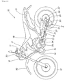
- FIG. 1 is a side view of an off-road type motorcycle to which the present invention is applied.
- the motorcycle 10 includes a main frame 11, a front fork 12 steerably attached at the front of the main frame 11, a front wheel 13 attached to the lower end of the front fork 12, an engine 14 suspended from the main frame 11, an exhaust pipe 16 for flowing exhaust gas discharged from the engine 14 to a muffler 15, a fuel tank 17 and a rider's seat 18 disposed on the main frame 11 from the front to the rear, a swing arm 21 attached to the rear of the main frame 11 via a rear cushion 19 so as to be capable of a vertical movement, and a rear wheel 22 attached at the rear end of the swing arm 21.
- a power transmission system mainly includes the engine 14, a transmission 23 provided below the engine 14, a drive gear 25 attached to an output shaft 24 of the transmission 23, a sprocket 26 attached to the rear wheel 22, and a chain 27 wound around the sprocket 26 and the drive gear 25.
- a chain guide 30 is attached to the lower surface of the rear portion of the swing arm 21 attached to the main frame 11 so as to be capable of a vertical movement via a mounting stay 28.
- the reference numeral 31 designates a chain cover
- reference numeral 32 designates a front fender
- reference numeral 33 designates a handle.
- the chain guide 30 encloses the chain 27 wound around the sprocket 26 so as to prevent the chain 27 wound around the sprocket 26 attached on a shaft of the rear wheel 22 for transmitting the drive power from coming off the sprocket 26 due to the vertical movement of the swing arm 21 and controls deflection of the chain 27 so as not to exceed a predetermined extent. In other words, it has a function to guide the chain 27 so as not to come off the sprocket 26 by controlling deflection of the chain 27.
- Fig. 2 is an enlarged view of a portion 2 in Fig. 1.
- the chain guide 30 includes a chain guide member 34 formed of abrasion resistant resilient material such as polyurethane rubber and a guide holder 35 of high-strength aluminum alloy.
- Mounting stays 28a, 28b are mounted to the lower surface 36 of the swing arm, and the chain guide member 34 and the guide holder 35 are fixed to the stays 28a, 28b via bolts 38 and nuts, not shown.
- a flange 41 is provided at the front end of the chain guide member 34, and the flange 41 is disposed so as to protrude from the front end 42 of the guide holder 35.
- Fig. 3 is a cross-sectional view taken along the line 3-3 in Fig. 2, including the chain guide member 34 attached to the mounting stay 28a mounted to the lower surface 36 of the swing arm via the bolts 38 and the nuts 39, the guide holder 35 attached to the mounting stay 28a via the bolt 38 and nut 39 while fitting on the outer surface 43L, 43R of the chain guide member 34, and a collar 44 fitted into the center of the chain guide member 34 via the bolt 38 and the nut 39.
- the drawing also shows that the chain 27 is passed through an opening 45 formed at the center of the chain guide member 34.
- the guide holder 35 is formed into a substantially U-shape by bending the lower ends of right and left walls 46L, 46R inward and connecting at the bottom portion 47 so that the left and right walls are tapered downward. Since the guide holder 35 is formed in such a manner that the left and right walls 46L, 46R are tapered downward, the possibility of reception of impact from below or from sides by, for example, stones or obstacles, may be reduced. As a consequence, the possibility of deformation and scarring of the guide holder 35 may be reduced.
- the left and right walls 46L, 46R and the bottom portion 47 connecting the walls constituting the guide holder 35 are adapted in such a manner that the bottom portion 47 is formed to be thinner than the left and right walls. Since the guide holder 35 is formed of the extruded member of substantially hollow square in cross section, the thickness of the bottom portion 47 can be formed to be thinner than the thickness of the left and right walls 46L, 46R, respectively.
- the weight of the guide holder 35 can be reduced while securing the strength of the left and right walls 46L, 46R which' corresponds to the stay mounting portion.
- Fig. 4 is an exploded perspective view of a chain guide according to the present invention, and the chain guide 30 can be formed by fitting the guide holder 35 to the chain guide member 34 as indicated by an arrow a.
- the flange 41 is provided at the front end of the chain guide member 34 and the front end 42 of the guide holder 35 is retained rearwards of the flange 41 by bringing the position of the front end 42 of the guide holder 35 under control of the flange 41.
- a guide member extension is extended on top of the chain guide member 34, and the guide member extension is formed with guide member mounting holes 37a, 37b.
- the guide holder 35 is formed with guide holder mounting holes 40a, 40b, 40c on the upper portion thereof.
- the guide member mounting hole 37a is aligned with the guide holder mounting hole 40a and the guide member mounting hole 37b is aligned with the guide holder mounting hole 40b, so as to be capable of being fixed to the mounting stay 28a via the bolt 38 and the nut 39 (See Fig. 3).
- the guide holder mounting holes 40a, 40b are formed so as to align with the holes of the mounting stay 28a (See Fig. 3), so as to be capable of being fixed to the mounting stay 28a via the bolt 38 and the nut 39.
- the guide holder mounting hole 40c is formed so as to align with the hole on the mounting stay 28b (See Fig. 2), so as to be capable of being fixed to the mounting stay 28b via the bolt 38 and the nut 39.
- the guide holder 35 is formed of the extruded member of aluminum alloy. That is, only cutting and machining is needed, and the pressing process is not necessary. Since the extruded member of aluminum alloy is used, the portion requiring the machining is small, and simultaneously, a higher dimensional accuracy than the press processing is obtained.
- the chain guide member 34 can be positioned accurately and assembled easily with respect to the guide holder 35.
- Fig. 5 is a cross sectional view taken along the line 5-5 in Fig. 2 showing that the flange 41 is provided at a front end of the chain guide member 34 and a front end 42 of the guide holder 35 is retained rearwards of the flange 41 by bringing the front end 42 of the guide holder 35 under control of the flange 41, as described above.
- the flange 41 includes formed left and right back side surfaces 48L, 48R, and the back bottom surface 49 (see Fig. 2) clamped between the left and right back side surfaces 48L, 48R. Then, the chain guide 30 is formed by bringing the left and right walls 46L, 46R of the front end 42 of the guide holder 35 into abutment with the left and right back side surfaces 48L, 48R, and bringing the bottom portion 47 at the front end 42 of the guide holder 35 into abutment with the back bottom surface 49.
- Fig. 6 is a manufacturing flowchart for the guide holder according to the present invention.
- the drawing (a) shows that the extruded member 52 of aluminum alloy having a predetermined cross-section is formed by an extruding die 51.
- the extruded member 52 of the aluminum alloy is formed into substantially U-shape with the left and right walls 46L, 46R tapered downward, and the thickness of the bottom portion 47 is formed to be thinner than the thickness of the left and right walls 46L, 46R.
- the guide holder is formed by using the extruded member 52 of a hollow square in cross section, the packed state for transportation is stable in comparison with the material of irregular shape in cross section, and thus the possibility of collapse of cargo piles can be reduced.
- the drawing (b) shows that the extruded member of aluminum alloy can be divided into two parts by cutting means 53 such as a revolving saw or the like. Since the extruded member 52 of a hollow square in cross section can be formed into a U-shape by dividing it into two parts, the extruding member 52 can be utilized effectively.
- the extruded member 52 of substantially hollow square shape in cross section is used by dividing into two parts, the cross sectional shape or the dimensional accuracy of the extruded member 52 can be effectively utilized as is, a predetermined dimensional accuracy required for the guide holder 35 (See Fig. 2) can be secured easily and reliably.
- Means for dividing the extruded member 52 is not limited to the cutting means. For example, it is allowed to be cut by thermal processing means such as laser or welding.
- the drawing (c) shows that the extruded member 52 formed into substantially U-shape by dividing into two parts can be processed to a predetermined shape by removing means such as cutting. Since the extruded member 52 is used, the portion requiring machining is small, and a higher dimensional accuracy than a method of press processing is obtained.
- the extruded member 52 of aluminum alloy By utilizing the extruded member 52 of aluminum alloy, thermal processing which corresponds to T5 is performed simultaneously during the extruding process, and hence a strength equivalent to the high-strength aluminum alloy which is used in the guide holder in the related art is secured. Therefore, the required process is only machining, and hence a number of processes such as thermal processing, pressing, bending, solution annealing, aging treatment, precision alignment is not necessary. Since the die for pressing process is not necessary, in particular, it is advantageous in terms of cost particularly when manufacturing a small amount.
- the means for processing the extruded member 52 divided into two parts into a predetermined shape is removing means by cutting in the embodiment, the method is not limited thereto.
- An optimal method is to be selected by considering constraint conditions in manufacture such as processing accuracy, equipment held, or cycle time required for processing.
- the drawing (d) shows a completed guide holder 35.
- the flange 41 is provided at a front end of the chain guide member 34 and the front end 42 of the guide holder 35 is retained rearwards of the flange 41 by bringing the front end 42 of the guide holder 35 under control of the flange 41.
- the chain 27 since the outside of the guide holder 35 is covered by the chain guide member 34, the chain 27 does not come into direct contact with the extremity 42 of the guide ⁇ holder 35. In other words, an impact due to contact of the chain 27 can be absorbed by the chain guide member 34, and in addition, impact due to contact of the chain guide 30 with respect to the surface of the road during off-road travel can also be absorbed and alleviated by the chain guide member 34. In addition, by using the abrasion resistance resilient member for the chain guide member 34, impact absorbing property may be improved.
- the material of the guide holder according to the present invention is extruded material of aluminum alloy in the embodiment, iron, magnesium, titanium, or an alloy thereof are allowed to use. Selection of the material is to be made considering required durability, strength, weight, dimensional accuracy, processability, and/or costs. It is also possible to apply the chain guide of the present invention for a general vehicle having a chain and sprocket for preventing the chain from coming apart.
- the chain guide of the invention can be widely applied to a motorcycle, a tricycle and vehicles for work.
- the chain guide of the present invention is e.g. suitable for a motorcycle.
Landscapes
- Engineering & Computer Science (AREA)
- Mechanical Engineering (AREA)
- Devices For Conveying Motion By Means Of Endless Flexible Members (AREA)
- Refuge Islands, Traffic Blockers, Or Guard Fence (AREA)
Abstract
Description
A
Since the guide holder is formed into the substantially U-shape with the left and right walls tapered downward, the possibility of reception of impact from below or from sides by, for example, stones or obstacles, may be reduced.
As a consequence, the possibility of deformation and breakage of the guide holder or of the mounting stay may be reduced.
By using the extruded member of aluminum alloy, required processes are only cutting and machining, and many processes including heat processing or pressing as in the related art are not necessary. Since a die for press processing is not necessary, it is advantageous in terms of cost particularly when manufacturing a small amount.
Since the guide holder is formed of the extruded member, the bottom portion can be formed to be thinner'than the left and right walls.
By forming the bottom portion of the guide holder to be thinner than the left and right walls, which corresponds to the stay mounting portion, the strength of the stay mounting portion is secured while reducing the weight of the guide holder.
Since the guide holder is formed of the extruded member, the bottom portion can be formed to be thinner than the left and right walls.
By forming the bottom portion of the guide holder to be thinner than the left and right walls, which corresponds to the stay mounting portion, the strength of the stay mounting portion is secured while reducing the weight of the guide holder.
Fig. 1 is a side view of an off-road type motorcycle to which the present invention is applied. The
The
A
The drawing also shows that the
Since the
As a consequence, the possibility of deformation and scarring of the
Since the
The
On the other hand, the
The drawing (a) shows that the extruded
In other words, the extruded
Since the extruded
Means for dividing the extruded
Since the extruded
Referring back to Fig. 5, in the
It is also possible to apply the chain guide of the present invention for a general vehicle having a chain and sprocket for preventing the chain from coming apart.
Claims (7)
- A chain guide comprising:characterized in thata chain guide member (34) which comes into contact with a chain;a guide holder (35) for holding the chain guide member (34), the guide holder (35) being mounted to the swing arm,
a flange (41) is provided at a front end portion of the chain guide member (34) and a front end of the guide holder (35) is retained rearwards of the flange by bringing the front end position of the guide holder (35) under control of the flange (41). - A chain guide according to Claim 1, characterized in that
the guide holder (35) is formed by bending the lower ends of left and right walls (46L, 46R) thereof inward and
connected at the bottom portion (47), so as to be formed into a substantially U-shape with the left and right walls (46L, 46R) tapered downward. - A chain guide according to Claim 1 or Claim 2, characterized in that
the guide holder (35) is formed of an extruded member (52) of aluminum alloy. - A chain guide according to Claim 3, characterized in that
the guide holder (35) is formed into a substantially U-shape by dividing the extruded member (52) of substantially hollow square in cross-section into two parts. - A chain guide according to Claim 3 or Claim 4, characterized in that
the left and right walls (46L, 46R) and the bottom portion (47) connecting the walls (46L, 46R), which constitute the guide holder (35), are adapted in such a manner that the bottom portion (47) is formed to be thinner than the left and right walls. - A chain guide comprising:a chain guide member (34) which comes into contact with a chain;a guide holder (35) for holding the chain guide member (34), the guide holder (35) being mounted to the swing arm, characterized in thatthe guide holder (35) is formed into a substantially U-shape by dividing an extruded member (52) of a substantially hollow square in cross section into two parts.
- A chain guide according to Claim 6, characterized in thatthe left and right walls (46L, 46R) and the bottom portion (47) connecting the lower ends of these walls (46L, 46R), which constitute the guide holder (35), are adapted in such a manner that the bottom portion (47) is formed to be thinner than the left and right walls (46L, 46R).
Applications Claiming Priority (2)
| Application Number | Priority Date | Filing Date | Title |
|---|---|---|---|
| JP2003307343 | 2003-08-29 | ||
| JP2003307343A JP4375716B2 (en) | 2003-08-29 | 2003-08-29 | Chain guide |
Publications (3)
| Publication Number | Publication Date |
|---|---|
| EP1510451A2 true EP1510451A2 (en) | 2005-03-02 |
| EP1510451A3 EP1510451A3 (en) | 2008-11-05 |
| EP1510451B1 EP1510451B1 (en) | 2012-12-05 |
Family
ID=34101259
Family Applications (1)
| Application Number | Title | Priority Date | Filing Date |
|---|---|---|---|
| EP04016564A Expired - Lifetime EP1510451B1 (en) | 2003-08-29 | 2004-07-14 | Chain guide |
Country Status (3)
| Country | Link |
|---|---|
| US (1) | US7691019B2 (en) |
| EP (1) | EP1510451B1 (en) |
| JP (1) | JP4375716B2 (en) |
Cited By (1)
| Publication number | Priority date | Publication date | Assignee | Title |
|---|---|---|---|---|
| GB2452577A (en) * | 2007-10-18 | 2009-03-11 | Matthew Chambers | Motorcycle chain tensioner |
Families Citing this family (34)
| Publication number | Priority date | Publication date | Assignee | Title |
|---|---|---|---|---|
| JP4607699B2 (en) * | 2005-08-04 | 2011-01-05 | 本田技研工業株式会社 | Chain guide device |
| JP4737750B2 (en) * | 2005-08-19 | 2011-08-03 | 本田技研工業株式会社 | Chain guide device |
| US7740554B2 (en) * | 2005-10-14 | 2010-06-22 | T.M. Designworks, Llc | Motorcycle chain guide |
| USD532720S1 (en) * | 2005-10-14 | 2006-11-28 | T.M. Designworks, Llc | Motorcycle chain guide |
| EP1963712A1 (en) * | 2005-12-13 | 2008-09-03 | LuK Lamellen und Kupplungsbau Beteiligungs KG | Guide arrangement for a wraparound means, and injection mould for manufacturing a guide arrangement |
| US20080227573A1 (en) * | 2007-02-16 | 2008-09-18 | Eric Strombeck | Derailleur Shield |
| USD601465S1 (en) | 2008-03-28 | 2009-10-06 | T.M. Designworks, Llc | Motorcycle chain guide |
| USD600600S1 (en) * | 2009-01-28 | 2009-09-22 | T.M. Designworks, Llc | Motorcycle chain guide |
| DE102009013339A1 (en) * | 2009-03-16 | 2010-09-23 | Jochen Klieber | Device for guiding a chain |
| JP5526968B2 (en) * | 2009-08-07 | 2014-06-18 | 株式会社ジェイテクト | Power transmission device |
| JP5486955B2 (en) * | 2010-02-19 | 2014-05-07 | 本田技研工業株式会社 | Chain guide device |
| US8534693B2 (en) | 2011-04-04 | 2013-09-17 | Specialized Bicycle Components, Inc. | Bicycle chain guide assembly |
| US9249867B2 (en) * | 2012-02-20 | 2016-02-02 | Gamut Usa | Retention mechanisms for bicycle drive trains |
| JP6190098B2 (en) * | 2012-06-14 | 2017-08-30 | 川崎重工業株式会社 | Sprocket cover for saddle riding type vehicle |
| US9327786B2 (en) * | 2012-08-17 | 2016-05-03 | Eko Sport, Inc. | Chain guard with unitary bracket extension |
| KR20140086151A (en) * | 2012-12-28 | 2014-07-08 | 현대자동차주식회사 | Chain guide member |
| JP5921039B2 (en) * | 2013-03-04 | 2016-05-24 | 株式会社椿本チエイン | Chain guide |
| DE102013003948B4 (en) * | 2013-03-07 | 2023-07-13 | Iwis Motorsysteme Gmbh & Co. Kg | Method for producing a tensioning or guide rail with a vibration absorber, tensioning or guide rail and endless drive with such |
| US9896145B2 (en) | 2013-09-18 | 2018-02-20 | Alan Stillwell | System and apparatus for a linkage guard |
| US9376161B2 (en) * | 2013-09-18 | 2016-06-28 | Alan Stillwell | System and apparatus for a linkage guard |
| US9469379B2 (en) * | 2014-06-02 | 2016-10-18 | T.M. Designworks, Llc | Motorcycle chain guide |
| USD793913S1 (en) * | 2014-06-02 | 2017-08-08 | T.M. Designworks, Llc | Motorcycle chain guide |
| USD794512S1 (en) * | 2014-06-02 | 2017-08-15 | T.M. Designworks, Llc | Motorcycle chain guide |
| WO2017013563A1 (en) * | 2015-07-17 | 2017-01-26 | Polisport Plásticos, Sa | Chain guide and use thereof |
| US11479322B2 (en) * | 2019-03-04 | 2022-10-25 | STFU Bike Inc. | Chain damper for a bicycle |
| JP7234075B2 (en) * | 2019-08-27 | 2023-03-07 | 本田技研工業株式会社 | saddle-riding vehicle |
| US11919593B2 (en) * | 2020-02-21 | 2024-03-05 | Honda Motor Co., Ltd. | Saddle-ride type vehicle |
| US11613326B2 (en) * | 2020-07-28 | 2023-03-28 | Eko Sport, Inc. | Two-piece upper chain guide |
| US11796040B2 (en) | 2021-01-22 | 2023-10-24 | Borgwarner Inc. | Method(s) to apply tension to increase drivetrain jump torque capacity |
| US12320425B2 (en) | 2021-01-22 | 2025-06-03 | Borgwarner Inc. | Tooth jump protection device |
| US12435774B2 (en) | 2021-01-22 | 2025-10-07 | Borgwarner, Inc. | Tooth jump protection device |
| USD1030564S1 (en) * | 2021-11-16 | 2024-06-11 | Pierre Dugardin | Chain guard |
| US12078245B2 (en) | 2022-05-31 | 2024-09-03 | Borgwarner Inc. | Face of tensioner guide or arm with pattern to influence chain system NVH performance |
| USD1104881S1 (en) * | 2024-05-06 | 2025-12-09 | T.M. Designworks, Llc | Chain guide for motorcycle |
Citations (2)
| Publication number | Priority date | Publication date | Assignee | Title |
|---|---|---|---|---|
| JPS58178043A (en) | 1982-04-08 | 1983-10-18 | Honda Motor Co Ltd | Chain guide apparatus |
| JPH05193549A (en) | 1992-01-14 | 1993-08-03 | Suzuki Motor Corp | Chain guide of motorcycle |
Family Cites Families (20)
| Publication number | Priority date | Publication date | Assignee | Title |
|---|---|---|---|---|
| US3885471A (en) * | 1973-03-07 | 1975-05-27 | Fedco Inc | Guard assembly for endless flexible drive members |
| US4158402A (en) * | 1977-10-11 | 1979-06-19 | Orville Romans | Motorcycle chainguard and lubricator |
| JPS5843876A (en) * | 1981-09-05 | 1983-03-14 | 本田技研工業株式会社 | Mud guard device for chain in motorcycle |
| US4733741A (en) * | 1986-09-02 | 1988-03-29 | Swanson Daniel L | Wear plate for a motorcycle |
| US4958469A (en) | 1989-05-16 | 1990-09-25 | Andersen Corporation | Collapsible window flange apparatus |
| JPH032952A (en) | 1989-05-30 | 1991-01-09 | Kyushu Nippon Denki Software Kk | Automatic production system for executing command train |
| JPH0520637A (en) | 1991-03-12 | 1993-01-29 | Sumitomo Metal Ind Ltd | Thin-film magnetic head |
| JPH06183536A (en) * | 1992-12-15 | 1994-07-05 | Sosei Kikai Kogyo Kk | Chain guide repair method and chain guide |
| JP2965878B2 (en) * | 1994-11-25 | 1999-10-18 | 株式会社シマノ | Chain guide positioning mechanism for bicycle front transmission |
| US5679084A (en) * | 1996-05-06 | 1997-10-21 | Daniels, Iii; Vernon James | Motorcycle roller chain guide |
| JP4806825B2 (en) * | 1999-04-07 | 2011-11-02 | シェフラー テクノロジーズ ゲゼルシャフト ミット ベシュレンクテル ハフツング ウント コンパニー コマンディートゲゼルシャフト | transmission |
| JP2001310789A (en) * | 2000-04-27 | 2001-11-06 | Yamaha Motor Co Ltd | Guide device for power transmission chain in saddle type vehicle |
| JP2002120786A (en) * | 2000-10-16 | 2002-04-23 | Honda Motor Co Ltd | Motorcycle chain guide device |
| US6533690B2 (en) * | 2001-04-30 | 2003-03-18 | Robert L. Barnett | Chain guide apparatus for bicycle |
| JP3357042B1 (en) * | 2002-01-25 | 2002-12-16 | 株式会社椿本チエイン | Sliding contact guide for transmission |
| US20030224891A1 (en) * | 2002-05-31 | 2003-12-04 | Joe Chou | Chain casing for a bicycle |
| CA2411313A1 (en) * | 2002-11-07 | 2004-05-07 | Ron Bergman | Rubber cushioned chain tensioner |
| US6939259B2 (en) * | 2003-04-25 | 2005-09-06 | Borgwarner Inc. | Two-shot unified chain tensioner arm or guide |
| USD532720S1 (en) * | 2005-10-14 | 2006-11-28 | T.M. Designworks, Llc | Motorcycle chain guide |
| US7740554B2 (en) * | 2005-10-14 | 2010-06-22 | T.M. Designworks, Llc | Motorcycle chain guide |
-
2003
- 2003-08-29 JP JP2003307343A patent/JP4375716B2/en not_active Expired - Lifetime
-
2004
- 2004-07-14 EP EP04016564A patent/EP1510451B1/en not_active Expired - Lifetime
- 2004-07-15 US US10/891,839 patent/US7691019B2/en not_active Expired - Fee Related
Patent Citations (2)
| Publication number | Priority date | Publication date | Assignee | Title |
|---|---|---|---|---|
| JPS58178043A (en) | 1982-04-08 | 1983-10-18 | Honda Motor Co Ltd | Chain guide apparatus |
| JPH05193549A (en) | 1992-01-14 | 1993-08-03 | Suzuki Motor Corp | Chain guide of motorcycle |
Cited By (2)
| Publication number | Priority date | Publication date | Assignee | Title |
|---|---|---|---|---|
| GB2452577A (en) * | 2007-10-18 | 2009-03-11 | Matthew Chambers | Motorcycle chain tensioner |
| GB2452577B (en) * | 2007-10-18 | 2009-08-26 | Matthew Chambers | Motorcycle chain tensioner |
Also Published As
| Publication number | Publication date |
|---|---|
| EP1510451A3 (en) | 2008-11-05 |
| JP4375716B2 (en) | 2009-12-02 |
| US7691019B2 (en) | 2010-04-06 |
| US20050159260A1 (en) | 2005-07-21 |
| JP2005075122A (en) | 2005-03-24 |
| EP1510451B1 (en) | 2012-12-05 |
Similar Documents
| Publication | Publication Date | Title |
|---|---|---|
| EP1510451B1 (en) | Chain guide | |
| US7806223B2 (en) | Frame of motorcycle and engine bracket | |
| US7708662B2 (en) | Vehicle apparatus having a chain guide device | |
| US7503575B2 (en) | Body frame of two-wheeled vehicle | |
| JP2001063671A (en) | Rear swing arm support structure for motorcycles | |
| CN110316296B (en) | Seat frame for motorcycles | |
| EP3378751B1 (en) | Rear fender supporting structure of saddle-type vehicle | |
| JP2019034606A (en) | Body frame of saddle riding type vehicle | |
| JP2001063667A (en) | Engine support structure for motorcycles | |
| US7316410B2 (en) | Frame structure of small vehicle | |
| JP7296518B2 (en) | saddle-riding vehicle | |
| JP2002326595A (en) | Electric bicycle | |
| JP7328436B2 (en) | saddle-riding vehicle | |
| JP4394774B2 (en) | Motorcycle | |
| JP2001063670A (en) | Body frame for motorcycles | |
| JP2009073289A (en) | Shift change device for saddle-ride type vehicles | |
| EP1470995B1 (en) | Load-carrying frame structure for a vehicle | |
| JP3701361B2 (en) | Stay structure for mounting accessory parts of motorcycles | |
| JP4441512B2 (en) | Motorcycle side stand | |
| US20070049059A1 (en) | Wire/pipe support device of motorcycle | |
| JP4414258B2 (en) | Motorcycle side stand | |
| JPH01164682A (en) | Seat fixture for motorcycle, etc. | |
| JP2001071979A (en) | Motorcycle | |
| JP2023148506A (en) | Backrest structure for saddle-riding type vehicle | |
| WO2020178848A1 (en) | Front cover of vehicle |
Legal Events
| Date | Code | Title | Description |
|---|---|---|---|
| PUAI | Public reference made under article 153(3) epc to a published international application that has entered the european phase |
Free format text: ORIGINAL CODE: 0009012 |
|
| AK | Designated contracting states |
Kind code of ref document: A2 Designated state(s): AT BE BG CH CY CZ DE DK EE ES FI FR GB GR HU IE IT LI LU MC NL PL PT RO SE SI SK TR |
|
| AX | Request for extension of the european patent |
Extension state: AL HR LT LV MK |
|
| PUAL | Search report despatched |
Free format text: ORIGINAL CODE: 0009013 |
|
| AK | Designated contracting states |
Kind code of ref document: A3 Designated state(s): AT BE BG CH CY CZ DE DK EE ES FI FR GB GR HU IE IT LI LU MC NL PL PT RO SE SI SK TR |
|
| AX | Request for extension of the european patent |
Extension state: AL HR LT LV MK |
|
| 17P | Request for examination filed |
Effective date: 20081022 |
|
| AKX | Designation fees paid |
Designated state(s): DE IT |
|
| 17Q | First examination report despatched |
Effective date: 20111230 |
|
| GRAP | Despatch of communication of intention to grant a patent |
Free format text: ORIGINAL CODE: EPIDOSNIGR1 |
|
| RIC1 | Information provided on ipc code assigned before grant |
Ipc: B62M 9/16 20060101AFI20120525BHEP Ipc: B62J 13/00 20060101ALI20120525BHEP |
|
| GRAS | Grant fee paid |
Free format text: ORIGINAL CODE: EPIDOSNIGR3 |
|
| GRAA | (expected) grant |
Free format text: ORIGINAL CODE: 0009210 |
|
| AK | Designated contracting states |
Kind code of ref document: B1 Designated state(s): DE IT |
|
| REG | Reference to a national code |
Ref country code: DE Ref legal event code: R096 Ref document number: 602004040272 Country of ref document: DE Effective date: 20130131 |
|
| REG | Reference to a national code |
Ref country code: DE Ref legal event code: R084 Ref document number: 602004040272 Country of ref document: DE Effective date: 20130513 |
|
| PLBE | No opposition filed within time limit |
Free format text: ORIGINAL CODE: 0009261 |
|
| STAA | Information on the status of an ep patent application or granted ep patent |
Free format text: STATUS: NO OPPOSITION FILED WITHIN TIME LIMIT |
|
| 26N | No opposition filed |
Effective date: 20130906 |
|
| PGFP | Annual fee paid to national office [announced via postgrant information from national office to epo] |
Ref country code: IT Payment date: 20130715 Year of fee payment: 10 |
|
| REG | Reference to a national code |
Ref country code: DE Ref legal event code: R097 Ref document number: 602004040272 Country of ref document: DE Effective date: 20130906 |
|
| PG25 | Lapsed in a contracting state [announced via postgrant information from national office to epo] |
Ref country code: IT Free format text: LAPSE BECAUSE OF NON-PAYMENT OF DUE FEES Effective date: 20140714 |
|
| PGFP | Annual fee paid to national office [announced via postgrant information from national office to epo] |
Ref country code: DE Payment date: 20170711 Year of fee payment: 14 |
|
| REG | Reference to a national code |
Ref country code: DE Ref legal event code: R119 Ref document number: 602004040272 Country of ref document: DE |
|
| PG25 | Lapsed in a contracting state [announced via postgrant information from national office to epo] |
Ref country code: DE Free format text: LAPSE BECAUSE OF NON-PAYMENT OF DUE FEES Effective date: 20190201 |