EP1510376A2 - Air conditioning system, in particular for a motor vehicle - Google Patents
Air conditioning system, in particular for a motor vehicle Download PDFInfo
- Publication number
- EP1510376A2 EP1510376A2 EP03292116A EP03292116A EP1510376A2 EP 1510376 A2 EP1510376 A2 EP 1510376A2 EP 03292116 A EP03292116 A EP 03292116A EP 03292116 A EP03292116 A EP 03292116A EP 1510376 A2 EP1510376 A2 EP 1510376A2
- Authority
- EP
- European Patent Office
- Prior art keywords
- air
- bypass
- air conditioning
- conditioning system
- heat exchanger
- Prior art date
- Legal status (The legal status is an assumption and is not a legal conclusion. Google has not performed a legal analysis and makes no representation as to the accuracy of the status listed.)
- Granted
Links
Images

Classifications
-
- B—PERFORMING OPERATIONS; TRANSPORTING
- B60—VEHICLES IN GENERAL
- B60H—ARRANGEMENTS OF HEATING, COOLING, VENTILATING OR OTHER AIR-TREATING DEVICES SPECIALLY ADAPTED FOR PASSENGER OR GOODS SPACES OF VEHICLES
- B60H1/00—Heating, cooling or ventilating [HVAC] devices
- B60H1/00007—Combined heating, ventilating, or cooling devices
- B60H1/00021—Air flow details of HVAC devices
- B60H1/00035—Air flow details of HVAC devices for sending an air stream of uniform temperature into the passenger compartment
- B60H1/0005—Air flow details of HVAC devices for sending an air stream of uniform temperature into the passenger compartment the air being firstly cooled and subsequently heated or vice versa
-
- B—PERFORMING OPERATIONS; TRANSPORTING
- B60—VEHICLES IN GENERAL
- B60H—ARRANGEMENTS OF HEATING, COOLING, VENTILATING OR OTHER AIR-TREATING DEVICES SPECIALLY ADAPTED FOR PASSENGER OR GOODS SPACES OF VEHICLES
- B60H1/00—Heating, cooling or ventilating [HVAC] devices
- B60H1/00007—Combined heating, ventilating, or cooling devices
- B60H1/00021—Air flow details of HVAC devices
- B60H2001/00114—Heating or cooling details
- B60H2001/00135—Deviding walls for separate air flows
Definitions
- the invention relates to an air conditioner, in particular for vehicles, with a Air conveyor and an evaporator.
- the invention has for its object to provide an air conditioning, the has an optimally small space, has only a small pressure loss and works very quietly.
- this object is achieved in that the particular designed as an evaporator heat exchanger a separator for Distribution of the heat exchanger flowing through, from the air conveyor subsidized air flow is associated with partial air flows.
- this separating element which is preferably designed as a partition, is from the outset the symmetry or asymmetry ratios Taken into account, so that in the places where the Air exits the desired mass flows and set temperatures.
- the air conditioner in a rear of a vehicle, so is arranged by means of the corresponding Separating element, a division of the air flow in partial air streams possible, such that, for example, at the B-pillars (B1, B2) and C-pillars (C1 and C2) the mass flows emerge symmetrically and, if desired, in each case air with the same temperature flows out.
- the separating element of the heat exchanger preferably asymmetrically divided into two corresponding zones.
- the asymmetry takes into account the different channel lengths to the B and / or C-pillars, so that sets a compensation and extent the air conditioning conditions inside the vehicle cab again symmetrical are.
- the invention is of course not on an additional air conditioning or a rear air conditioning limited.
- At least one bypass for introducing of bypass air in at least one of the coming from the heat exchanger Partial air flows provided.
- the bypass air happens the heat exchanger is not and is therefore different than the associated Partial air flow - not thermally influenced.
- each partial air flow is bypassed for the Initiation of bypass air is assigned, that is, in the already mentioned two-tone design, two bypasses are provided and the heat exchanger is divided by the separating element into two zones, wherein the a zone with associated bypass the left side of the motor vehicle and the other zone with associated bypass the right side of the motor vehicle provided.
- each bypass has a bypass mixing valve.
- the air conveyor a Suction is, seen in the flow direction- the heat exchanger is downstream and thus the air through the heat exchanger sucks and also encourages the air sucking through the bypasses.
- the air conveyor is designed two-tone, that is each partial air flow with associated bypass air flow is separated from a Suction zone of the air conveyor. This can be done, for example take place that the air conveyor several, not ventilation technology with each other having communicating wheels.
- At least one Bypass air flow channel-like on the heat exchanger or a part of this is passed.
- this is not done laterally, but preferably under or above the heat exchanger, so that the side dimension the air conditioning is not increased.
- the channel-like line realized by the bypass air flow by means of a tunnel, that is, the associated Bypass air undermines the heat exchanger.
- FIG. 1 shows, in a schematic representation, a plan view of a vehicle 1, which is designed as a passenger car 2.
- the vehicle 1 has an engine compartment 3, a passenger compartment 4 and a trunk 5.
- Im Engine compartment 3 is an unillustrated drive motor and a Front air conditioner 6, which forms a main air conditioner 7 of the vehicle 1. It supplies a left-side air outlet A, a right-side air outlet A1 as well as a central air outlet A2.
- the air outlets A, A1 and A2 are housed in the area of the dashboard of the vehicle 1.
- the backrests of the front seats 8 of the vehicle 1 is on the right Side the so-called B1-pillar and on the left side the so-called B2-pillar the body arranged.
- the rear area of the vehicle 1 is located on the right side of the C1 column and on the left side the C2 column. According to the names of the mentioned columns There are air outlets on these, that is, there is a right-sided Air outlet B1, a left-side air outlet B2 and a right-sided Air outlet C1 and finally a left-side air outlet C2.
- the air outlets B1, B2, C1 and C2 belong to an auxiliary air conditioning system 9, the -im Contrary to the main air conditioning system 7 referred to as a rear air conditioner 10 becomes.
- a rear air conditioner 10 As can be seen in FIG. 1, it is under the right front seat 8 arranged and supplies-as the name says- the rear area of the vehicle 1.
- suitable air ducts 11 and blower 12 supplies the auxiliary air conditioning 9 the air outlets B1, B2, C1 and C2.
- FIG. 2 shows, schematically, an evaporator 13 formed heat exchanger 14 of the auxiliary air conditioning system 9. It can be seen that by means of an air conveyor, not shown, air (arrow 15) is promoted, which passes the evaporator 13.
- the evaporator 13 is -in Seen flow direction- a separating element 16 downstream or upstream, which divides the air (arrow 15) into partial air streams 17, 18, the division due to an asymmetrical arrangement to the longitudinal central axis of the evaporator 13 is different in size, that is, the mass flow of the partial air flow 17 is greater than that of the partial air flow 18. Accordingly, the distance of the separating element 16 from the associated side edge of the evaporator 13 in the case of the partial air flow 17, the dimension X and in the case of the partial air flow 18 is the measure Y, where X ⁇ Y.
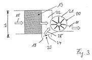
- FIG. 3 illustrates - also in a schematic representation - at some the components of the auxiliary air conditioning system 9, that the evaporator 13 a bypass 19 is assigned.
- Downstream of the evaporator 13 is the air conveyor 20, which accordingly formed as a suction device 21 is. Due to the suction effect of the air conveyor 20 air is according to Arrow 15 sucked, which passes through the evaporator 13 and cools there. The air enters a mixing chamber 22, in which the bypass 19 opens.
- the Bypass 19 has a bypass mixing valve 23 in the form of a mixing flap 24th on, by means of a control or regulating device, not shown the additional air conditioner 9 in a corresponding rotational position is adjusted, so that -these Dreh ein- a assigned bypass air flow 25 sets.
- the mixing chamber 22 meets the air coming from the evaporator 13 to the air of the bypass air flow 25th and mixes there. Together, the mixed air is promoted by the Suction of the air conveyor 20- introduced into the air duct 11 and directed from there to the corresponding air outlets of the vehicle 1.
- the separating element 16 is of simplicity half-not shown. It should only be clarified that the of Evaporator 13 incoming air flow with the bypass air flow 25 a Angle includes, in the embodiment shown, 90 ° or is about 90 °. Consequently, the bypass air flows laterally into the air, which comes from the evaporator 13. In this coming from the evaporator 13 Air may in particular be partial air flows 17 or 18 act (see Figure 2). Because of this lateral airflow leaves realize a very narrow design, which in the figure 13 schematically marked with the dimension s.
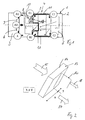
- FIG. 4 illustrates, in a more concrete illustration, the structure of the rear air conditioning system
- the invention does not refer to such Air conditioning is limited, but for example, in front air conditioning systems or in general terms for air conditioning systems can.
- a lower part 26 of a housing 27 of the additional air conditioning 9. It carries in its interior 28 as a heat exchanger 14th trained evaporator 13 and a lower part 29 of the otherwise not closer Furthermore, a bypass 19 and a Bypass 30 recognizable.
- the bypasses 19, 30 each have bypass mixing valves 23, 31, the two actuators 32, 33 in the operating mode appropriate positions are brought.
- the two bypass mixing valves 23 and 31 are formed as mixing flaps 24 and 34.
- the evaporator 13 is arranged in the interior 28 of the housing 27 of the auxiliary air conditioning system 9, that it has a distance t to the inside 35 of the housing 27. This Distance t is realized by means of spacers 36.
- Dividing element 16 designed as a dividing wall 38 divides the evaporator 13 in a zone X and a zone Y, wherein -as above already set out - an asymmetric division is realized.
- the zone X extends below the evaporator 13 of the bypass 19 in Shape of a triangular channel 39, that is, this channel 39 forms a Tunnel 40, which leads to the zone Y of the heat exchanger 14.
- the cross section of the tunnel 40 is triangular and also the Shape of the partition 38 designed substantially triangular.
- Zone X results in air being sucked in and out of air inlet 37 the effect of the partition wall 38 as a partial air flow 17 under the evaporator thirteenth reaches in the area of zone X and there - ascending upward - the heat exchanger 14 in the area of zone X interspersed.
- On the now cooled Air meets-over the bypass 30- a bypass airflow 41.
- the size of this Bypass air flow 41 is determined by the opening angle of the mixing flap 34.
- the mixed air then passes to the suction effect unfolding, assigned Impeller of the air conveyor 20 and from there into the air ducts 11 to the associated air outlets B1 and C1.
- the following air flow sets in: Due to the suction effect of this zone Y associated impeller of the air conveyor 20 air is sucked through the air inlet 37 which sweeps as a partial air stream 18 from above the zone Y of the evaporator 13 and then passes down through the heat exchanger 14. In accordance with the opened mixing flap 24 of the bypass 19, a bypass air flow 25 enters the bypass 19 and underflows due to the formation of the tunnel 40, the zone X of the evaporator 13. The bypass air flow 25 occurs below the zone Y of the evaporator 13 and meets there on the partial air flow 18, which has passed through the heat exchanger 14 in the zone Y.
Abstract
Description
Die Erfindung betrifft eine Klimaanlage, insbesondere für Fahrzeuge, mit einer Luftfördereinrichtung und einem Verdampfer.The invention relates to an air conditioner, in particular for vehicles, with a Air conveyor and an evaporator.
Grundsätzlich besteht das Bestreben, Klimaanlagen mit kleinem Bauraum herzustellen. Dies ist insbesondere in Fahrzeugen und ganz besonders bei Zusatzklimaanlagen in Fahrzeugen von Bedeutung. Zusatzklimaanlagen sind in manchen Fahrzeugen aufgrund der geforderten Temperaturverteilung notwendig. Sie klimatisieren den Heckbereich des Fahrzeugs. Aufgrund beengter Platzverhältnisse im Fahrzeug ist gegebenenfalls nur eine asymmetrische Anordnung zur Längsmittelachse möglich, so das sich aufgrund unterschiedlich langer Kanäle für die Bestromung der rechten und linken Fahrzeughälfte unterschiedliche Massenströme und Lufttemperaturen einstellen. Um diese Unterschiede auszugleichen, werden zusätzliche Regler eingesetzt, die einerseits Platz einnehmen und andererseits Druckverluste und Geräuschentwicklungen mit sich bringen.Basically, there is the desire air conditioning systems with a small space manufacture. This is especially true in vehicles and especially at Additional air conditioning in vehicles of importance. Additional air conditioners are in some vehicles due to the required temperature distribution necessary. They air-condition the rear area of the vehicle. Due to cramped Space in the vehicle is possibly only an asymmetric Arrangement for the longitudinal central axis possible, so that due to different long channels for the power supply of the right and left half of the vehicle set different mass flows and air temperatures. To compensate for these differences, additional controllers are used, on the one hand take up space and on the other hand pressure losses and Noise developments bring with it.
Der Erfindung liegt die Aufgabe zugrunde, eine Klimaanlage zu schaffen, die einen optimal kleinen Bauraum aufweist, nur einen kleinen Druckverlust besitzt und sehr geräuscharm arbeitet. The invention has for its object to provide an air conditioning, the has an optimally small space, has only a small pressure loss and works very quietly.
Diese Aufgabe wird erfindungsgemäß dadurch gelöst, dass dem insbesondere als Verdampfer ausgebildeten Wärmetauscher ein Trennelement zur Aufteilung des den Wärmetauscher durchströmenden, von der Luftfördereinrichtung geförderten Luftstromes in Teilluftströme zugeordnet ist. Aufgrund dieses Trennelements, das vorzugsweise als Trennwand ausgebildet ist, wird von vornherein den Symmetrie- beziehungsweise Asymmetrie-Verhältnissen Rechnung getragen, so dass sich an den Orten, an denen die Luft austritt die gewünschten Massenströme und Temperaturen einstellen. Liegt beispielsweise eine asymmetrische Einbauanordnung der Klimaanlage in einem Heck eines Fahrzeugs vor, so ist mittels des entsprechend angeordneten Trennelements eine Aufteilung des Luftstromes in Teilluftströme möglich, derart, dass beispielsweise an den B-Säulen (B1, B2) und C-Säulen (C1 und C2) die Massenströme symmetrisch austreten und -sofern gewünscht- jeweils Luft mit gleicher Temperatur ausströmt. Insbesondere ist daher eine Zweizonigkeit geschaffen, wobei das Trennelement den Wärmetauscher vorzugsweise asymmetrisch in zwei entsprechende Zonen aufteilt. Die Asymmetrie berücksichtigt die unterschiedlichen Kanallängen zu den B-und/oder C-Säulen, so dass sich eine Kompensation einstellt und insoweit die lufttechnischen Verhältnisse im Innern der Fahrzeugkabine wieder symmetrisch sind. Die Erfindung ist selbstverständlich nicht auf eine Zusatzklimaanlage oder eine Heckklimaanlage beschränkt.This object is achieved in that the particular designed as an evaporator heat exchanger a separator for Distribution of the heat exchanger flowing through, from the air conveyor subsidized air flow is associated with partial air flows. by virtue of this separating element, which is preferably designed as a partition, is from the outset the symmetry or asymmetry ratios Taken into account, so that in the places where the Air exits the desired mass flows and set temperatures. For example, is an asymmetric installation arrangement of the air conditioner in a rear of a vehicle, so is arranged by means of the corresponding Separating element, a division of the air flow in partial air streams possible, such that, for example, at the B-pillars (B1, B2) and C-pillars (C1 and C2) the mass flows emerge symmetrically and, if desired, in each case air with the same temperature flows out. In particular therefore created a two-tone, wherein the separating element of the heat exchanger preferably asymmetrically divided into two corresponding zones. The asymmetry takes into account the different channel lengths to the B and / or C-pillars, so that sets a compensation and extent the air conditioning conditions inside the vehicle cab again symmetrical are. The invention is of course not on an additional air conditioning or a rear air conditioning limited.
Nach einer Weiterbildung der Erfindung ist mindestens ein Bypass zum Einleiten von Bypassluft in mindestens einen der vom Wärmetauscher kommenden Teilluftströme vorgesehen. Durch das Zuführen von Bypassluft lässt sich der Massenstrom und die Temperatur beeinflussen. Die Bypassluft passiert den Wärmetauscher nicht und wird daher -anders als der zugehörige Teilluftstrom- nicht thermisch beeinflusst.According to a development of the invention, at least one bypass for introducing of bypass air in at least one of the coming from the heat exchanger Partial air flows provided. By supplying bypass air leaves the mass flow and the temperature influence each other. The bypass air happens the heat exchanger is not and is therefore different than the associated Partial air flow - not thermally influenced.
Insbesondere ist vorgesehen, dass jedem Teilluftstrom ein Bypass für das Einleiten von Bypassluft zugeordnet ist, das heißt, bei der bereits erwähnten zweizonigen Ausgestaltung sind zwei Bypässe vorgesehen und der Wärmetauscher wird mittels des Trennelements in zwei Zonen unterteilt, wobei die eine Zone mit zugehörigem Bypass die linke Seite des Kraftfahrzeugs und die andere Zone mit zugehörigem Bypass die rechte Seite des Kraftfahrzeugs versorgt.In particular, it is provided that each partial air flow is bypassed for the Initiation of bypass air is assigned, that is, in the already mentioned two-tone design, two bypasses are provided and the heat exchanger is divided by the separating element into two zones, wherein the a zone with associated bypass the left side of the motor vehicle and the other zone with associated bypass the right side of the motor vehicle provided.
Um die Menge der zugemischten Bypassluft steuern beziehungsweise regeln zu können, weist jeder Bypass ein Bypassmischventil auf.To control or regulate the amount of mixed bypass air each bypass has a bypass mixing valve.
Ferner ist von Vorteil, in mindestens einem der vom Wärmetauscher kommenden Teilluftströme der zugeordnete Bypassluftstrom seitlich, insbesondere in einem Winkel, zugeführt wird. Dieser Winkel kann insbesondere 90° betragen. Aufgrund dieser seitlichen Zuführung der Bypassluft zum vom Wärmetauscher kommenden Teilluftstrom ergibt sich eine sehr schlanke Bauform, da die Bypassluft nicht seitlich an dem Verdampfer entlanggeführt werden muss.Furthermore, it is advantageous in at least one of the coming from the heat exchanger Partial air flows the associated bypass air flow laterally, in particular at an angle, is supplied. This angle can be in particular 90 ° be. Due to this lateral supply of the bypass air to the from Heat exchanger coming partial air flow results in a very slender Design, as the bypass air is not guided along the side of the evaporator must become.
Von besonderer Bedeutung ist ferner, dass die Luftfördereinrichtung eine Saugeinrichtung ist, die -in Strömungsrichtung gesehen- dem Wärmetauscher nachgeschaltet ist und insofern die Luft durch den Wärmetauscher saugt und auch die Luft durch die Bypässe saugend fördert. Insbesondere ist vorgesehen, dass die Luftfördereinrichtung zweizonig gestaltet ist, das heißt jeder Teilluftstrom mit zugehörigem Bypassluftstrom wird separat von einer Zone der Luftfördereinrichtung angesaugt. Dies kann beispielsweise dadurch erfolgen, dass die Luftfördereinrichtung mehrere, lufttechnisch nicht miteinander kommunizierende Laufräder aufweist.Of particular importance is further that the air conveyor a Suction is, seen in the flow direction- the heat exchanger is downstream and thus the air through the heat exchanger sucks and also encourages the air sucking through the bypasses. In particular provided that the air conveyor is designed two-tone, that is each partial air flow with associated bypass air flow is separated from a Suction zone of the air conveyor. This can be done, for example take place that the air conveyor several, not ventilation technology with each other having communicating wheels.
Nach einer Weiterbildung der Erfindung ist vorgesehen, dass mindestens ein Bypassluftstrom kanalartig am Wärmetauscher oder einem Teil von diesem vorbeigeführt wird. Dies erfolgt jedoch nicht seitlich, sondern bevorzugt unter- oder oberhalb des Wärmetauschers, so dass sich die Seitenabmessung der Klimaanlage nicht vergrößert. Insbesondere ist die kanalartige Leitung des Bypassluftstroms mittels eines Tunnels realisiert, das heißt, die zugehörige Bypassluft untertunnelt den Wärmetauscher.According to a development of the invention, it is provided that at least one Bypass air flow channel-like on the heat exchanger or a part of this is passed. However, this is not done laterally, but preferably under or above the heat exchanger, so that the side dimension the air conditioning is not increased. In particular, the channel-like line realized by the bypass air flow by means of a tunnel, that is, the associated Bypass air undermines the heat exchanger.
Die Zeichnungen veranschaulichen die Erfindung anhand eines Ausführungsbeispiels, und zwar zeigt:
- Figur 1
- eine schematische Draufsicht auf ein mit Klimaanlage ausgestattetes Fahrzeug,
Figur 2- eine schematische Ansicht der Luftaufteilung an einem Wärmetauscher, insbesondere Verdampfer, der Klimaanlage,
Figur 3- ein Prinzipbild der Luftführung der Klimaanlage und
Figur 4- eine Klimaanlage mit geöffnetem Gehäuse, wobei die obere Gehäusehälfte mit entsprechenden Einbauten nicht wiedergegeben ist.
- FIG. 1
- a schematic plan view of a vehicle equipped with air conditioning,
- FIG. 2
- a schematic view of the air distribution on a heat exchanger, in particular evaporator, the air conditioning,
- FIG. 3
- a schematic diagram of the air duct of the air conditioning and
- FIG. 4
- an air conditioner with the housing open, the upper half of the housing with corresponding internals is not reproduced.
Die Figur 1 zeigt -in schematischer Darstellung- eine Draufsicht auf ein Fahrzeug
1, das als Personenkraftwagen 2 ausgebildet ist. Das Fahrzeug 1 besitzt
einen Motorraum 3, eine Fahrgastzelle 4 sowie einen Kofferraum 5. Im
Motorraum 3 befindet sich ein nicht dargestellter Antriebsmotor sowie eine
Front-Klimaanlage 6, die eine Hauptklimaanlage 7 des Fahrzeugs 1 bildet.
Sie versorgt einen linksseitigen Luftauslass A, einen rechtseitigen Luftauslass
A1 sowie eine zentralen Luftauslass A2. Die Luftauslässe A, A1 und A2
sind im Bereich des Armaturenbretts des Fahrzeugs 1 untergebracht. Im Bereich
der Rücklehnen der Vordersitze 8 des Fahrzeugs 1 ist auf der rechten
Seite die so genannte B1-Säule und auf der linken Seite die so genannte B2-Säule
der Karosserie angeordnet. Im rückwärtigen Bereich des Fahrzeugs 1
befindet sich auf der rechten Seiten die C1-Säule und auf der linken Seite
die C2-Säule. Den Bezeichnungen der genannten Säulen entsprechend befinden
sich Luftauslässe an diesen, das heißt, es gibt einen rechtseitigen
Luftauslass B1, einen linksseitigen Luftauslass B2 sowie einen rechtseitigen
Luftauslass C1 und schließlich einen linksseitigen Luftauslass C2. Die Luftauslässe
B1, B2, C1 und C2 gehören einer Zusatzklimaanlage 9 an, die -im
Gegensatz zur Hauptklimaanlage 7- als Heck-Klimaanlage 10 bezeichnet
wird. Sie ist -wie aus der Figur 1 entnehmbar- unter dem rechten Vordersitz
8 angeordnet und versorgt -wie der Name sagt- den Heckbereich des Fahrzeugs
1. Mittels geeigneter Luftkanäle 11 und Gebläse 12 versorgt die Zusatzklimaanlage
9 die Luftauslässe B1, B2, C1 und C2. FIG. 1 shows, in a schematic representation, a plan view of a vehicle
1, which is designed as a
Die Figur 2 zeigt -in schematischer Darstellung- einen als Verdampfer 13
ausgebildeten Wärmetauscher 14 der Zusatzklimaanlage 9. Es ist erkennbar,
dass mittels einer nicht dargestellten Luftfördereinrichtung Luft (Pfeil 15)
gefördert wird, die den Verdampfer 13 passiert. Dem Verdampfer 13 ist -in
Strömungsrichtung gesehen- ein Trennelement 16 nach- oder vorgeschaltet,
das die Luft (Pfeil 15) in Teilluftströme 17, 18 aufteilt, wobei die Aufteilung
aufgrund einer asymmetrischen Anordnung zur Längsmittelachse des Verdampfers
13 unterschiedlich groß ist, das heißt, der Massenstrom des Teilluftstroms
17 ist größer als der des Teilluftstroms 18. Dementsprechend beträgt
der Abstand des Trennelements 16 von der zugeordneten Seitenkante
des Verdampfers 13 im Falle des Teilluftstroms 17 das Maß X und im Falle
des Teilluftstroms 18 das Maß Y, wobei X ≠ Y ist.FIG. 2 shows, schematically, an
Aufgrund dieser unterschiedlich großen Teilluftströme 18 ist es möglich, die
aufgrund der asymmetrischen Anordnung der Zusatzklimaanlage 9 im Innern
des Fahrzeugs 1 gemäß Figur 1 auftretenden unterschiedlichen Druckverluste
und Temperatureinstellungen derart zu kompensieren, dass -eine gleiche
Bedienpult-Einstellung der rechten und der linken Seite des Fahrzeugs vorausgesetzt-die
Luftströme symmetrisch mit gleichem Massenstrom aus den
zugeordneten Luftauslässen B2 und C2 beziehungsweise B1 und C1 austreten
und dementsprechend auch eine gleiche Temperaturverteilung vorliegt.Due to these different sized
Die Figur 3 verdeutlicht -ebenfalls in schematischer Darstellung- an einigen
der Bauteile der Zusatzklimaanlage 9, dass dem Verdampfer 13 ein Bypass
19 zugeordnet ist. Stromabwärts des Verdampfers 13 befindet sich die Luftfördereinrichtung
20, die dementsprechend als Saugeinrichtung 21 ausgebildet
ist. Aufgrund der Saugwirkung der Luftfördereinrichtung 20 wird Luft gemäß
Pfeil 15 angesaugt, die den Verdampfer 13 durchsetzt und dort abkühlt.
Die Luft gelangt in einen Mischraum 22, in den der Bypass 19 mündet. Der
Bypass 19 weist ein Bypass-Mischventil 23 in Form einer Mischklappe 24
auf, die mittels einer nicht dargestellten Steuer- beziehungsweise Regelungseinrichtung
der Zusatzklimaanlage 9 in eine entsprechende Drehstellung
eingestellt wird, so dass sich -entsprechend dieser Drehstellung- ein
zugeordneter Bypassluftstrom 25 einstellt. In der Mischkammer 22 trifft die
vom Verdampfer 13 kommende Luft auf die Luft des Bypassluftstromes 25
und mischt sich dort. Gemeinsam wird die Mischluft -gefördert durch die
Saugwirkung der Luftfördereinrichtung 20- in den Luftkanal 11 eingebracht
und von dort zu den entsprechenden Luftauslässen des Fahrzeugs 1 geleitet.
In der Darstellung der Figur 3 ist das Trennelement 16 -der Einfachheit
halber- nicht dargestellt. Es soll lediglich verdeutlicht werden, dass der vom
Verdampfer 13 kommende Luftstrom mit dem Bypassluftstrom 25 einen
Winkel einschließt, der -im gezeigten Ausführungsbeispiel- 90° beziehungsweise
etwa 90° beträgt. Mithin strömt die Bypassluft seitlich in die Luft ein,
die vom Verdampfer 13 kommt. Bei dieser vom Verdampfer 13 kommenden
Luft kann es sich insbesondere um Teilluftströme 17 beziehungsweise 18
handeln (vergleiche Figur 2). Aufgrund dieser seitlichen Luftzuströmung lässt
sich eine sehr schmale Bauform realisieren, die in der Figur 13 schematisch
mit dem Maß s gekennzeichnet ist.Figure 3 illustrates - also in a schematic representation - at some
the components of the auxiliary air conditioning system 9, that the evaporator 13 a
Die Figur 4 verdeutlicht -in konkreterer Darstellung- den Aufbau der Heck-Klimaanlage 10, wobei die Erfindung selbstverständlich nicht auf eine derartige Klimaanlage begrenzt ist, sondern beispielsweise auch bei Front-Klimaanlagen oder in allgemeiner Form bei Klimaanlagen angewendet werden kann.FIG. 4 illustrates, in a more concrete illustration, the structure of the rear air conditioning system Of course, the invention does not refer to such Air conditioning is limited, but for example, in front air conditioning systems or in general terms for air conditioning systems can.
Erkennbar ist aus der Figur 4 ein Unterteil 26 eines Gehäuses 27 der Zusatzklimaanlage
9. Es trägt in seinem Innern 28 den als Wärmetauscher 14
ausgebildeten Verdampfer 13 sowie ein Unterteil 29 der ansonsten nicht näher
dargestellten Luftfördereinrichtung 20. Ferner ist ein Bypass 19 und ein
Bypass 30 erkennbar. Die Bypässe 19, 30 weisen jeweils Bypass-Mischventile
23, 31 auf, die von zwei Aktuatoren 32, 33 in der Betriebsart
entsprechende Stellungen gebracht sind. Die beiden Bypass-Mischventile 23
und 31 sind als Mischklappen 24 und 34 ausgebildet. Der Verdampfer 13 ist
derart im Innern 28 des Gehäuses 27 der Zusatzklimaanlage 9 angeordnet,
dass er einen Abstand t zur Innenseite 35 des Gehäuses 27 aufweist. Dieser
Abstand t wird mittels Abstandshaltern 36 realisiert. Die Anordnung ist derart
getroffen, dass der Abstand t sich in Richtung auf einen Lufteinlass 37 keilförmig
vergrößert. Das als Trennwand 38 ausgebildete Trennelement 16 teilt
den Verdampfer 13 in eine Zone X und eine Zone Y, wobei -wie vorstehend
bereits dargelegt- eine asymmetrische Teilung realisiert ist. Über die Länge
der Zone X erstreckt sich unterhalb des Verdampfers 13 der Bypass 19 in
Form eines dreieckförmigen Kanals 39, das heißt, dieser Kanal 39 bildet einen
Tunnel 40, der zur Zone Y des Wärmetauschers 14 führt.Visible from the figure 4, a
Aufgrund der erwähnten Schrägstellung des Verdampfers 13 innerhalb des
Gehäuses 27 ist der Querschnitt des Tunnels 40 dreieckförmig und auch die
Gestalt der Trennwand 38 im Wesentlichen dreieckförmig gestaltet.Due to the mentioned inclination of the
Es ergibt sich folgende Funktion: Bei in Betrieb befindlicher Luftfördereinrichtung
20 wird mittels zweier strömungstechnisch voneinander getrennter,
nicht dargestellter Laufräder eine der Zone X zugeordnete Saugwirkung und
eine der Zone Y zugeordnete Saugwirkung entfaltet. Dies hat in Bezug auf
die Zone X zur Folge, dass Luft am Lufteinlass 37 angesaugt und -aufgrund
der Wirkung der Trennwand 38 als Teilluftstrom 17 unter den Verdampfer 13
im Bereich der Zone X gelangt und dort -nach oben aufsteigend- den Wärmetauscher
14 im Bereich der Zone X durchsetzt. Auf die nunmehr gekühlte
Luft trifft -über den Bypass 30- ein Bypassluftstrom 41. Die Größe dieses
Bypassluftstrom 41 bestimmt sich durch den Öffnungswinkel der Mischklappe
34. Die Mischluft gelangt dann zum die Saugwirkung entfaltenden, zugeordneten
Laufrad der Luftfördereinrichtung 20 und von dort in die Luftkanäle
11 zu den zugeordneten Luftauslässen B1 und C1.The following function results: With the air conveyor in
In Bezug auf die Zone Y des Verdampfers 13 stellt sich folgende Luftströmung
ein: Aufgrund der Sogwirkung des dieser Zone Y zugeordneten Laufrades
der Luftfördereinrichtung 20 wird über den Lufteinlass 37 Luft angesaugt,
die als Teilluftstrom 18 von oben über die Zone Y des Verdampfers 13
streicht und dann nach unten durch den Wärmetauscher 14 hindurchtritt. Bei
entsprechend geöffneter Mischklappe 24 des Bypasses 19 tritt ein Bypassluftstrom
25 in den Bypass 19 ein und unterläuft aufgrund der Ausbildung
des Tunnels 40 die Zone X des Verdampfers 13. Der Bypassluftstrom 25 tritt
unterhalb der Zone Y des Verdampfers 13 aus und trifft dort auf den Teilluftstrom
18, der den Wärmetauscher 14 in der Zone Y durchsetzt hat. Dort mischen
sich die beiden Luftströme und gelangen dann zum zugeordneten
Laufrad der Luftfördereinrichtung 20 und von dort zu den zugeordneten Luftkanälen
und zu den Luftauslässen B2 und C2.
Der Figur 4 ist deutlich entnehmbar, dass der jeweilige Teilluftstrom unter
einem Winkel von etwa 90° auf den zugeordneten Bypassluftstrom trifft.With respect to the zone Y of the
It can clearly be seen from FIG. 4 that the respective partial air flow strikes the assigned bypass air flow at an angle of approximately 90 °.
Claims (12)
Priority Applications (3)
| Application Number | Priority Date | Filing Date | Title |
|---|---|---|---|
| AT03292116T ATE430047T1 (en) | 2003-08-27 | 2003-08-27 | AIR CONDITIONING, ESPECIALLY FOR VEHICLES |
| DE50311480T DE50311480D1 (en) | 2003-08-27 | 2003-08-27 | Air conditioning, in particular for vehicles |
| EP03292116A EP1510376B1 (en) | 2003-08-27 | 2003-08-27 | Air conditioning system, in particular for a motor vehicle |
Applications Claiming Priority (1)
| Application Number | Priority Date | Filing Date | Title |
|---|---|---|---|
| EP03292116A EP1510376B1 (en) | 2003-08-27 | 2003-08-27 | Air conditioning system, in particular for a motor vehicle |
Publications (3)
| Publication Number | Publication Date |
|---|---|
| EP1510376A2 true EP1510376A2 (en) | 2005-03-02 |
| EP1510376A3 EP1510376A3 (en) | 2005-04-27 |
| EP1510376B1 EP1510376B1 (en) | 2009-04-29 |
Family
ID=34089758
Family Applications (1)
| Application Number | Title | Priority Date | Filing Date |
|---|---|---|---|
| EP03292116A Expired - Lifetime EP1510376B1 (en) | 2003-08-27 | 2003-08-27 | Air conditioning system, in particular for a motor vehicle |
Country Status (3)
| Country | Link |
|---|---|
| EP (1) | EP1510376B1 (en) |
| AT (1) | ATE430047T1 (en) |
| DE (1) | DE50311480D1 (en) |
Citations (8)
| Publication number | Priority date | Publication date | Assignee | Title |
|---|---|---|---|---|
| US2647451A (en) * | 1949-07-30 | 1953-08-04 | E A Lab Inc | Automobile heater |
| DE3911494C1 (en) * | 1989-04-08 | 1990-10-04 | Bayerische Motoren Werke Ag, 8000 Muenchen, De | Vehicle heating device with at least two air-inlet flows, the temperatures of which are controlled in different ways |
| EP0768197A2 (en) * | 1995-10-12 | 1997-04-16 | Denso Corporation | Air conditioning apparatus |
| US5673747A (en) * | 1994-09-30 | 1997-10-07 | Japan Climate Systems Corporation | Rear air-conditioning unit for use in vehicle |
| EP0835773A1 (en) * | 1996-10-11 | 1998-04-15 | Valeo Climatisation | Heating and/or air conditioning system for a vehicle with separate control for the left and right side of the interior |
| DE19919132A1 (en) * | 1999-04-27 | 2000-11-02 | Valeo Klimasysteme Gmbh | Vehicle ventilation system has heat exchanger in fresh air duct and associated on output side with device forming two or more separate or insulated ducts each leading to a mixing chamber |
| US20010029162A1 (en) * | 2000-03-31 | 2001-10-11 | Takeshi Yoshinori | Vehicle air conditioner having air suction port for each seat |
| US6311763B1 (en) * | 1999-04-28 | 2001-11-06 | Denso Corporation | Vehicle air conditioner |
-
2003
- 2003-08-27 DE DE50311480T patent/DE50311480D1/en not_active Expired - Lifetime
- 2003-08-27 EP EP03292116A patent/EP1510376B1/en not_active Expired - Lifetime
- 2003-08-27 AT AT03292116T patent/ATE430047T1/en not_active IP Right Cessation
Patent Citations (8)
| Publication number | Priority date | Publication date | Assignee | Title |
|---|---|---|---|---|
| US2647451A (en) * | 1949-07-30 | 1953-08-04 | E A Lab Inc | Automobile heater |
| DE3911494C1 (en) * | 1989-04-08 | 1990-10-04 | Bayerische Motoren Werke Ag, 8000 Muenchen, De | Vehicle heating device with at least two air-inlet flows, the temperatures of which are controlled in different ways |
| US5673747A (en) * | 1994-09-30 | 1997-10-07 | Japan Climate Systems Corporation | Rear air-conditioning unit for use in vehicle |
| EP0768197A2 (en) * | 1995-10-12 | 1997-04-16 | Denso Corporation | Air conditioning apparatus |
| EP0835773A1 (en) * | 1996-10-11 | 1998-04-15 | Valeo Climatisation | Heating and/or air conditioning system for a vehicle with separate control for the left and right side of the interior |
| DE19919132A1 (en) * | 1999-04-27 | 2000-11-02 | Valeo Klimasysteme Gmbh | Vehicle ventilation system has heat exchanger in fresh air duct and associated on output side with device forming two or more separate or insulated ducts each leading to a mixing chamber |
| US6311763B1 (en) * | 1999-04-28 | 2001-11-06 | Denso Corporation | Vehicle air conditioner |
| US20010029162A1 (en) * | 2000-03-31 | 2001-10-11 | Takeshi Yoshinori | Vehicle air conditioner having air suction port for each seat |
Non-Patent Citations (1)
| Title |
|---|
| "INDIVIDUELL KLIMATISIEREN" ATZ AUTOMOBILTECHNISCHE ZEITSCHRIFT, FRANCKH'SCHE VERLAGSHANDLUNG. STUTTGART, DE, Bd. 101, Nr. 9, September 1999 (1999-09), Seiten 684-688, XP000847319 ISSN: 0001-2785 * |
Also Published As
| Publication number | Publication date |
|---|---|
| ATE430047T1 (en) | 2009-05-15 |
| DE50311480D1 (en) | 2009-06-10 |
| EP1510376B1 (en) | 2009-04-29 |
| EP1510376A3 (en) | 2005-04-27 |
Similar Documents
| Publication | Publication Date | Title |
|---|---|---|
| EP0841201B2 (en) | Heating or air conditioning installation for motor vehicles. | |
| EP1110769B1 (en) | Heating or air conditioning system for motor vehicle | |
| DE102004027689A1 (en) | Air conditioning for a motor vehicle | |
| EP2015948B1 (en) | Motor vehicle air conditioning system | |
| EP2062763A1 (en) | Nozzle, especially for a vehicle | |
| DE3925726C2 (en) | ||
| EP1742810B1 (en) | Heater or air conditioner for a vehicle | |
| EP1641642B1 (en) | Air-conditioning system | |
| EP2011675B1 (en) | Air conditioner | |
| EP2048010B1 (en) | Vehicle air conditioning system | |
| EP1510375B1 (en) | Air conditioning installation and method for operating one such installation | |
| DE102007013432A1 (en) | Hot air channel for air conditioning system of motor vehicle, has separating web, where hot air leaving channel is divided into two hot air partial flows such that each flow supplies hot air to respective air outlets of system | |
| EP1510376A2 (en) | Air conditioning system, in particular for a motor vehicle | |
| EP2088011B1 (en) | Casing assembly for a motor vehicle air conditioning system | |
| DE102006055164A1 (en) | Heating and ventilation system i.e. multi-zone heating, ventilation and air conditioning system, for e.g. motor vehicle, has mixing volume including air flow control unit attached to another mixing volume and hot air volume | |
| DE102004030672B4 (en) | V-shaped heat exchanger arrangement of a heating air conditioning | |
| EP2011676B1 (en) | Air conditioner | |
| DE102006012400B4 (en) | Heating and ventilation system for a vehicle with a cold air bypass downstream of the mixing flap | |
| DE10353191A1 (en) | Automotive air conditioning | |
| EP1674308B1 (en) | Air conditioning unit, in particular an auxiliary air conditioning unit with electrical supplementary heater | |
| DE102007025371B4 (en) | Air conditioning apparatus, in particular for motor vehicles | |
| EP1972473B1 (en) | Air conditioning system for a motor vehicle | |
| EP1733904B1 (en) | Air conditioning unit for a vehicle comprising a cold-air bypass | |
| EP2100759B1 (en) | Partition wall for vehicle air conditioning units | |
| EP1641641B1 (en) | Ventilation device, especially for a heating or air conditioning system of a motor vehicle |
Legal Events
| Date | Code | Title | Description |
|---|---|---|---|
| PUAI | Public reference made under article 153(3) epc to a published international application that has entered the european phase |
Free format text: ORIGINAL CODE: 0009012 |
|
| AK | Designated contracting states |
Kind code of ref document: A2 Designated state(s): AT BE BG CH CY CZ DE DK EE ES FI FR GB GR HU IE IT LI LU MC NL PT RO SE SI SK TR |
|
| AX | Request for extension of the european patent |
Extension state: AL LT LV MK |
|
| PUAL | Search report despatched |
Free format text: ORIGINAL CODE: 0009013 |
|
| AK | Designated contracting states |
Kind code of ref document: A3 Designated state(s): AT BE BG CH CY CZ DE DK EE ES FI FR GB GR HU IE IT LI LU MC NL PT RO SE SI SK TR |
|
| AX | Request for extension of the european patent |
Extension state: AL LT LV MK |
|
| RAP1 | Party data changed (applicant data changed or rights of an application transferred) |
Owner name: BEHR FRANCE ROUFFACH SAS |
|
| 17P | Request for examination filed |
Effective date: 20051027 |
|
| AKX | Designation fees paid |
Designated state(s): AT BE BG CH CY CZ DE DK EE ES FI FR GB GR HU IE IT LI LU MC NL PT RO SE SI SK TR |
|
| 17Q | First examination report despatched |
Effective date: 20060424 |
|
| GRAP | Despatch of communication of intention to grant a patent |
Free format text: ORIGINAL CODE: EPIDOSNIGR1 |
|
| GRAS | Grant fee paid |
Free format text: ORIGINAL CODE: EPIDOSNIGR3 |
|
| GRAA | (expected) grant |
Free format text: ORIGINAL CODE: 0009210 |
|
| AK | Designated contracting states |
Kind code of ref document: B1 Designated state(s): AT BE BG CH CY CZ DE DK EE ES FI FR GB GR HU IE IT LI LU MC NL PT RO SE SI SK TR |
|
| REG | Reference to a national code |
Ref country code: GB Ref legal event code: FG4D Free format text: NOT ENGLISH |
|
| REG | Reference to a national code |
Ref country code: CH Ref legal event code: EP |
|
| REF | Corresponds to: |
Ref document number: 50311480 Country of ref document: DE Date of ref document: 20090610 Kind code of ref document: P |
|
| REG | Reference to a national code |
Ref country code: IE Ref legal event code: FG4D |
|
| NLV1 | Nl: lapsed or annulled due to failure to fulfill the requirements of art. 29p and 29m of the patents act | ||
| PG25 | Lapsed in a contracting state [announced via postgrant information from national office to epo] |
Ref country code: FI Free format text: LAPSE BECAUSE OF FAILURE TO SUBMIT A TRANSLATION OF THE DESCRIPTION OR TO PAY THE FEE WITHIN THE PRESCRIBED TIME-LIMIT Effective date: 20090429 Ref country code: PT Free format text: LAPSE BECAUSE OF FAILURE TO SUBMIT A TRANSLATION OF THE DESCRIPTION OR TO PAY THE FEE WITHIN THE PRESCRIBED TIME-LIMIT Effective date: 20090829 Ref country code: ES Free format text: LAPSE BECAUSE OF FAILURE TO SUBMIT A TRANSLATION OF THE DESCRIPTION OR TO PAY THE FEE WITHIN THE PRESCRIBED TIME-LIMIT Effective date: 20090809 |
|
| PG25 | Lapsed in a contracting state [announced via postgrant information from national office to epo] |
Ref country code: NL Free format text: LAPSE BECAUSE OF FAILURE TO SUBMIT A TRANSLATION OF THE DESCRIPTION OR TO PAY THE FEE WITHIN THE PRESCRIBED TIME-LIMIT Effective date: 20090429 Ref country code: SE Free format text: LAPSE BECAUSE OF FAILURE TO SUBMIT A TRANSLATION OF THE DESCRIPTION OR TO PAY THE FEE WITHIN THE PRESCRIBED TIME-LIMIT Effective date: 20090729 Ref country code: SI Free format text: LAPSE BECAUSE OF FAILURE TO SUBMIT A TRANSLATION OF THE DESCRIPTION OR TO PAY THE FEE WITHIN THE PRESCRIBED TIME-LIMIT Effective date: 20090429 |
|
| REG | Reference to a national code |
Ref country code: IE Ref legal event code: FD4D |
|
| PG25 | Lapsed in a contracting state [announced via postgrant information from national office to epo] |
Ref country code: CZ Free format text: LAPSE BECAUSE OF FAILURE TO SUBMIT A TRANSLATION OF THE DESCRIPTION OR TO PAY THE FEE WITHIN THE PRESCRIBED TIME-LIMIT Effective date: 20090429 Ref country code: IE Free format text: LAPSE BECAUSE OF FAILURE TO SUBMIT A TRANSLATION OF THE DESCRIPTION OR TO PAY THE FEE WITHIN THE PRESCRIBED TIME-LIMIT Effective date: 20090429 Ref country code: EE Free format text: LAPSE BECAUSE OF FAILURE TO SUBMIT A TRANSLATION OF THE DESCRIPTION OR TO PAY THE FEE WITHIN THE PRESCRIBED TIME-LIMIT Effective date: 20090429 Ref country code: DK Free format text: LAPSE BECAUSE OF FAILURE TO SUBMIT A TRANSLATION OF THE DESCRIPTION OR TO PAY THE FEE WITHIN THE PRESCRIBED TIME-LIMIT Effective date: 20090429 Ref country code: RO Free format text: LAPSE BECAUSE OF FAILURE TO SUBMIT A TRANSLATION OF THE DESCRIPTION OR TO PAY THE FEE WITHIN THE PRESCRIBED TIME-LIMIT Effective date: 20090429 |
|
| PG25 | Lapsed in a contracting state [announced via postgrant information from national office to epo] |
Ref country code: SK Free format text: LAPSE BECAUSE OF FAILURE TO SUBMIT A TRANSLATION OF THE DESCRIPTION OR TO PAY THE FEE WITHIN THE PRESCRIBED TIME-LIMIT Effective date: 20090429 |
|
| BERE | Be: lapsed |
Owner name: BEHR FRANCE ROUFFACH SAS Effective date: 20090831 |
|
| PLBE | No opposition filed within time limit |
Free format text: ORIGINAL CODE: 0009261 |
|
| STAA | Information on the status of an ep patent application or granted ep patent |
Free format text: STATUS: NO OPPOSITION FILED WITHIN TIME LIMIT |
|
| PG25 | Lapsed in a contracting state [announced via postgrant information from national office to epo] |
Ref country code: BG Free format text: LAPSE BECAUSE OF FAILURE TO SUBMIT A TRANSLATION OF THE DESCRIPTION OR TO PAY THE FEE WITHIN THE PRESCRIBED TIME-LIMIT Effective date: 20090729 Ref country code: MC Free format text: LAPSE BECAUSE OF NON-PAYMENT OF DUE FEES Effective date: 20090831 |
|
| REG | Reference to a national code |
Ref country code: CH Ref legal event code: PL |
|
| 26N | No opposition filed |
Effective date: 20100201 |
|
| GBPC | Gb: european patent ceased through non-payment of renewal fee |
Effective date: 20090827 |
|
| PG25 | Lapsed in a contracting state [announced via postgrant information from national office to epo] |
Ref country code: LI Free format text: LAPSE BECAUSE OF NON-PAYMENT OF DUE FEES Effective date: 20090831 Ref country code: CH Free format text: LAPSE BECAUSE OF NON-PAYMENT OF DUE FEES Effective date: 20090831 |
|
| PG25 | Lapsed in a contracting state [announced via postgrant information from national office to epo] |
Ref country code: BE Free format text: LAPSE BECAUSE OF NON-PAYMENT OF DUE FEES Effective date: 20090831 |
|
| PG25 | Lapsed in a contracting state [announced via postgrant information from national office to epo] |
Ref country code: GR Free format text: LAPSE BECAUSE OF FAILURE TO SUBMIT A TRANSLATION OF THE DESCRIPTION OR TO PAY THE FEE WITHIN THE PRESCRIBED TIME-LIMIT Effective date: 20090730 |
|
| PG25 | Lapsed in a contracting state [announced via postgrant information from national office to epo] |
Ref country code: AT Free format text: LAPSE BECAUSE OF NON-PAYMENT OF DUE FEES Effective date: 20090827 Ref country code: GB Free format text: LAPSE BECAUSE OF NON-PAYMENT OF DUE FEES Effective date: 20090827 |
|
| PG25 | Lapsed in a contracting state [announced via postgrant information from national office to epo] |
Ref country code: IT Free format text: LAPSE BECAUSE OF FAILURE TO SUBMIT A TRANSLATION OF THE DESCRIPTION OR TO PAY THE FEE WITHIN THE PRESCRIBED TIME-LIMIT Effective date: 20090429 |
|
| PG25 | Lapsed in a contracting state [announced via postgrant information from national office to epo] |
Ref country code: LU Free format text: LAPSE BECAUSE OF NON-PAYMENT OF DUE FEES Effective date: 20090827 |
|
| REG | Reference to a national code |
Ref country code: FR Ref legal event code: ST Effective date: 20110502 |
|
| PG25 | Lapsed in a contracting state [announced via postgrant information from national office to epo] |
Ref country code: HU Free format text: LAPSE BECAUSE OF FAILURE TO SUBMIT A TRANSLATION OF THE DESCRIPTION OR TO PAY THE FEE WITHIN THE PRESCRIBED TIME-LIMIT Effective date: 20091030 |
|
| PG25 | Lapsed in a contracting state [announced via postgrant information from national office to epo] |
Ref country code: FR Free format text: LAPSE BECAUSE OF NON-PAYMENT OF DUE FEES Effective date: 20100831 |
|
| PG25 | Lapsed in a contracting state [announced via postgrant information from national office to epo] |
Ref country code: TR Free format text: LAPSE BECAUSE OF FAILURE TO SUBMIT A TRANSLATION OF THE DESCRIPTION OR TO PAY THE FEE WITHIN THE PRESCRIBED TIME-LIMIT Effective date: 20090429 |
|
| PG25 | Lapsed in a contracting state [announced via postgrant information from national office to epo] |
Ref country code: CY Free format text: LAPSE BECAUSE OF FAILURE TO SUBMIT A TRANSLATION OF THE DESCRIPTION OR TO PAY THE FEE WITHIN THE PRESCRIBED TIME-LIMIT Effective date: 20090429 |
|
| PGFP | Annual fee paid to national office [announced via postgrant information from national office to epo] |
Ref country code: FR Payment date: 20090907 Year of fee payment: 7 |
|
| REG | Reference to a national code |
Ref country code: DE Ref legal event code: R082 Ref document number: 50311480 Country of ref document: DE Representative=s name: GRAUEL, ANDREAS, DIPL.-PHYS. DR. RER. NAT., DE Ref country code: DE Ref legal event code: R081 Ref document number: 50311480 Country of ref document: DE Owner name: MAHLE INTERNATIONAL GMBH, DE Free format text: FORMER OWNER: BEHR FRANCE ROUFFACH S.A.S., ROUFFACH, FR |
|
| PGFP | Annual fee paid to national office [announced via postgrant information from national office to epo] |
Ref country code: DE Payment date: 20180831 Year of fee payment: 16 |
|
| REG | Reference to a national code |
Ref country code: DE Ref legal event code: R119 Ref document number: 50311480 Country of ref document: DE |
|
| PG25 | Lapsed in a contracting state [announced via postgrant information from national office to epo] |
Ref country code: DE Free format text: LAPSE BECAUSE OF NON-PAYMENT OF DUE FEES Effective date: 20200303 |