EP1510333A1 - Method of forming multi-metallic articles from multi-metallic sheets - Google Patents
Method of forming multi-metallic articles from multi-metallic sheets Download PDFInfo
- Publication number
- EP1510333A1 EP1510333A1 EP04104111A EP04104111A EP1510333A1 EP 1510333 A1 EP1510333 A1 EP 1510333A1 EP 04104111 A EP04104111 A EP 04104111A EP 04104111 A EP04104111 A EP 04104111A EP 1510333 A1 EP1510333 A1 EP 1510333A1
- Authority
- EP
- European Patent Office
- Prior art keywords
- metallic
- metallic sheet
- differing
- blank
- component
- Prior art date
- Legal status (The legal status is an assumption and is not a legal conclusion. Google has not performed a legal analysis and makes no representation as to the accuracy of the status listed.)
- Withdrawn
Links
Images


Classifications
-
- B—PERFORMING OPERATIONS; TRANSPORTING
- B23—MACHINE TOOLS; METAL-WORKING NOT OTHERWISE PROVIDED FOR
- B23K—SOLDERING OR UNSOLDERING; WELDING; CLADDING OR PLATING BY SOLDERING OR WELDING; CUTTING BY APPLYING HEAT LOCALLY, e.g. FLAME CUTTING; WORKING BY LASER BEAM
- B23K26/00—Working by laser beam, e.g. welding, cutting or boring
- B23K26/20—Bonding
- B23K26/21—Bonding by welding
- B23K26/24—Seam welding
-
- B—PERFORMING OPERATIONS; TRANSPORTING
- B23—MACHINE TOOLS; METAL-WORKING NOT OTHERWISE PROVIDED FOR
- B23K—SOLDERING OR UNSOLDERING; WELDING; CLADDING OR PLATING BY SOLDERING OR WELDING; CUTTING BY APPLYING HEAT LOCALLY, e.g. FLAME CUTTING; WORKING BY LASER BEAM
- B23K1/00—Soldering, e.g. brazing, or unsoldering
- B23K1/0008—Soldering, e.g. brazing, or unsoldering specially adapted for particular articles or work
-
- B—PERFORMING OPERATIONS; TRANSPORTING
- B23—MACHINE TOOLS; METAL-WORKING NOT OTHERWISE PROVIDED FOR
- B23K—SOLDERING OR UNSOLDERING; WELDING; CLADDING OR PLATING BY SOLDERING OR WELDING; CUTTING BY APPLYING HEAT LOCALLY, e.g. FLAME CUTTING; WORKING BY LASER BEAM
- B23K20/00—Non-electric welding by applying impact or other pressure, with or without the application of heat, e.g. cladding or plating
- B23K20/06—Non-electric welding by applying impact or other pressure, with or without the application of heat, e.g. cladding or plating by means of high energy impulses, e.g. magnetic energy
-
- B—PERFORMING OPERATIONS; TRANSPORTING
- B23—MACHINE TOOLS; METAL-WORKING NOT OTHERWISE PROVIDED FOR
- B23K—SOLDERING OR UNSOLDERING; WELDING; CLADDING OR PLATING BY SOLDERING OR WELDING; CUTTING BY APPLYING HEAT LOCALLY, e.g. FLAME CUTTING; WORKING BY LASER BEAM
- B23K2101/00—Articles made by soldering, welding or cutting
- B23K2101/18—Sheet panels
- B23K2101/185—Tailored blanks
-
- B—PERFORMING OPERATIONS; TRANSPORTING
- B23—MACHINE TOOLS; METAL-WORKING NOT OTHERWISE PROVIDED FOR
- B23K—SOLDERING OR UNSOLDERING; WELDING; CLADDING OR PLATING BY SOLDERING OR WELDING; CUTTING BY APPLYING HEAT LOCALLY, e.g. FLAME CUTTING; WORKING BY LASER BEAM
- B23K2103/00—Materials to be soldered, welded or cut
- B23K2103/16—Composite materials
Definitions
- the invention relates to the field of forming multi-metallic articles and more specifically forming articles from multi-metallic sheet blanks created especially to create the specified article.
- tubes comprising differing types of steel into a single vehicle component.
- hydro-formed tubes comprised of differing types of compatible steels (high strength low alloy, galvanized steel, and plain carbon steel) are used.
- tubes made of dis-similar metal types first connected end-to-end and thereafter subject to forming as a composite tube through bending and/or hydro-forming. It is also known to form frame elements for vehicles using dis-similar metallic members joined together.
- the present invention is directed to simplifying the process for making multi-metallic articles in general.
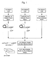
- multi-metallic sheets are first fabricated and thereafter formed into a final component.
- sheet blanks of the desired metals are first fabricated using conventionally the most cost effective methods to create such blanks.
- the blanks are joined, again using the most cost effective techniques, to form a multi-metallic blank of the desired multi-metallic composition and orientation.
- the multi-metallic blank is rolled and/or otherwise formed into a shape suitable for hydro-forming and/or other bending process or stamping process into a suitable shape for an article designed as a component element being created.
- the resulting multi-metallic article whether used in a vehicle, article of furniture, pipe element, etc, can take full advantage of the respective performance characteristics of the various metallic elements in that specific application.
- the present invention is directed to a method of efficiently fabricating a multi-metallic blank for later forming into a multi-metallic component having desired strength, stiffness, crush, and other performance characteristics.
- the method includes joining metallic sheets of differing composition, i.e., aluminum, steel, stainless steel, magnesium, using known processes such as pulse welding, laser welding, and weldbrazing, to fabricate multi-metallic sheet blanks that are then formed, as a whole, into multi-metallic components.
- the final multi-metallic component may have differing metallic surfaces along either or both its length and/or perimeter and/or ends.
- vehicle elements that, along a certain length, need to perform as stiff, non-deflecting mounting elements for suspension and/or engine/drive train components can be a specified alloy of a certain type.
- a vehicle component that is supporting seating, fluid transfer, duct work, or is specified as crash energy absorbing can be comprised of a lighter differing metal that serves that role most efficiently.
- These multi-metallic features can be side-to-side with an eventual upwardlyor inwardly directed surface of the component having one selected metal specified and an opposing outwardly or downwardly directed surface, for example, having another metal specified.
- the method first involves the step of fabricating metallic sheet blanks of the desired metallic specification.
- These sheets can be comprised of varying metals of differing types and/or thicknesses and/or performance characteristics, i.e., stainless steel of various specification and strength, aluminum and magnesium likewise specified according to design and performance requirements, and at varying thicknesses.
- the metallic sheets blanks are then arranged to be joined in a specified orientation according to the performance requirements of the final component.
- the multi-metallic blank is then formed by any suitable combination of hydroforming, stamping, roll forming, or stretch forming to create a desired shape for the specified component, i.e., a vehicle frame member, cross member, floor, suspension or drive train element, chair seat/legs, cabinet portion, industrial railing, refrigeration unit frame/housing element, etc.
- a desired shape for the specified component i.e., a vehicle frame member, cross member, floor, suspension or drive train element, chair seat/legs, cabinet portion, industrial railing, refrigeration unit frame/housing element, etc.
- the respective multi-metallic sheet blanks 10 and 15 as shown in Figs. 2 and 4 include differing metallic materials 12, 13, and 17, as specified according to the performance requirements of the final articles.
- the final articles 14 and 16 position the selected material(s) according to a specified placement. For example, a steel element 17 is positioned along a rectangular tube form 16 to a specified location for attachment to a vehicle suspension mount.
Landscapes
- Engineering & Computer Science (AREA)
- Mechanical Engineering (AREA)
- Physics & Mathematics (AREA)
- Optics & Photonics (AREA)
- Plasma & Fusion (AREA)
- Laser Beam Processing (AREA)
- Body Structure For Vehicles (AREA)
Abstract
Description
Claims (16)
- A method of creating a multi-metallic article, comprising the steps of:providing a first metallic sheet member from a first metal,providing a second metallic sheet member from a second metal differing in type from said first metal,securing said first metallic sheet member to said second metallic sheet member to create a multi-metallic sheet blank,forming said multi-metallic sheet blank into a multi-metallic article.
- A method as in claim 1, further comprising the steps of:providing a third metallic sheet from a third metal differing from said first and second metals,securing said third metallic sheet to said multi-metallic sheet blank prior to forming said multi-metallic sheet blank into a multi-metallic article.
- A method as in claim 1, wherein:said securing step uses magnetic pulse welding to secure said first metallic sheet to said second metallic sheet.
- A method as in claim 1, wherein:said securing step uses laser welding to secure said first metallic sheet to said second metallic sheet.
- A method as in claim 1, wherein:said securing step uses weldbrazing to secure said first metallic sheet to said second metallic sheet.
- A method as in claim 1, wherein:said multi-metallic article is formed so as to have said first and second differing metals oriented along its length.
- A method as in claim 1, wherein:said multi-metallic article is formed so as to have said first and second differing metals oriented around its perimeter.
- A method of creating a multi-metallic vehicle component, comprising the steps of:providing a first metallic sheet member from a first metal,providing a second metallic sheet member from a second metal differing in type from said first metal,securing said first metallic sheet member to said second metallic sheet member to create a multi-metallic sheet blank,forming said multi-metallic sheet blank into a multi-metallic vehicle component.
- A method as in claim 8, further comprising the steps of:providing a third metallic sheet from a third metal differing from said first and second metals,securing said third metallic sheet to said multi-metallic sheet blank prior to forming said multi-metallic sheet blank into a multi-metallic vehicle component.
- A method as in claim 8, wherein:said securing step uses magnetic pulse welding to secure said first metallic sheet to said second metallic sheet.
- A method as in claim 8, wherein:said securing step uses laser welding to secure said first metallic sheet to said second metallic sheet.
- A method as in claim 8, wherein:said securing step uses weldbrazing to secure said first metallic sheet to said second metallic sheet.
- A method as in claim 8, wherein:said multi-metallic component is formed so as to have said first and second differing metals oriented along its length.
- A method as in claim 8, wherein:said multi-metallic component is formed so as to have said first and second differing metals oriented around its perimeter.
- A method as in claim 13, wherein:said component is a vehicle frame element.
- A method as in claim 14, wherein:said component is a vehicle frame element.
Applications Claiming Priority (2)
| Application Number | Priority Date | Filing Date | Title |
|---|---|---|---|
| US648804 | 2003-08-27 | ||
| US10/648,804 US20050045603A1 (en) | 2003-08-27 | 2003-08-27 | Method of forming multi-metallic articles from multi-metallic sheets |
Publications (1)
| Publication Number | Publication Date |
|---|---|
| EP1510333A1 true EP1510333A1 (en) | 2005-03-02 |
Family
ID=34104669
Family Applications (1)
| Application Number | Title | Priority Date | Filing Date |
|---|---|---|---|
| EP04104111A Withdrawn EP1510333A1 (en) | 2003-08-27 | 2004-08-26 | Method of forming multi-metallic articles from multi-metallic sheets |
Country Status (4)
| Country | Link |
|---|---|
| US (1) | US20050045603A1 (en) |
| EP (1) | EP1510333A1 (en) |
| AR (1) | AR045526A1 (en) |
| BR (1) | BRPI0403599A (en) |
Cited By (1)
| Publication number | Priority date | Publication date | Assignee | Title |
|---|---|---|---|---|
| US20150298257A1 (en) * | 2012-09-06 | 2015-10-22 | GM Global Technology Operations LLC | Laser welded structural fender inner blank for mass optimization |
Families Citing this family (5)
| Publication number | Priority date | Publication date | Assignee | Title |
|---|---|---|---|---|
| EP1935551B1 (en) * | 2006-12-18 | 2011-06-29 | GM Global Technology Operations, Inc. | Method of magnetic impulse welding of sheets, one of the sheets having at least one attachment region inclined at an angle to the sheet plane |
| KR101352517B1 (en) | 2007-06-08 | 2014-01-16 | 엘지전자 주식회사 | Portable terminal and its URL connecting method |
| US7997643B2 (en) * | 2009-06-26 | 2011-08-16 | GM Global Technology Operations LLC | Roof assembly for a vehicle |
| EP2377640A1 (en) * | 2010-04-16 | 2011-10-19 | Ferro Umformtechnik GmbH & Co. KG | Method of producing a basin body, in particular a tipping trough for a transport vehicle using laser welding process ; corresponding basin body, in particular a tipping trough for a transport vehicle and basin body for a transport vehicle |
| US20240383064A1 (en) * | 2021-10-01 | 2024-11-21 | Ohio State Innovation Foundation | Method of forming an impulse weld |
Citations (8)
| Publication number | Priority date | Publication date | Assignee | Title |
|---|---|---|---|---|
| US4560855A (en) * | 1982-09-08 | 1985-12-24 | Nippon Steel Corporation | Method for joining of articles by energy beam and apparatus for controlling said method |
| US4881430A (en) * | 1988-09-06 | 1989-11-21 | Hubbard Arthur J | Method of making heterogeneous blade-like metallic cutter member |
| US5318213A (en) * | 1990-11-30 | 1994-06-07 | British Aerospace Public Limited Company | Explosive bonding |
| EP1201345A1 (en) * | 2000-10-23 | 2002-05-02 | L'air Liquide, S.A. à Directoire et Conseil de Surveillance pour l'Etude et l'Exploitation des Procédés Georges Claude | Welding-brazing TIG method for galvanized sheets |
| EP1216782A2 (en) * | 2000-12-20 | 2002-06-26 | ThyssenKrupp Stahl AG | Method for end-to-end joining of two workpieces made of a thermally plasticizable material, in particular metal, and in particular for sheet-like material |
| US20020166843A1 (en) * | 2001-05-14 | 2002-11-14 | Pei-Chung Wang | Method for electrical resistance welding thin metal sheets together for automotive vehicle structures |
| US20030038118A1 (en) * | 2001-02-08 | 2003-02-27 | Sun Peter C. | Programmable pogo welding apparatus and method |
| JP2003071530A (en) * | 2001-06-18 | 2003-03-11 | Moltec:Kk | Metal sheet laminate model and metal sheet laminate model and modeling method |
Family Cites Families (14)
| Publication number | Priority date | Publication date | Assignee | Title |
|---|---|---|---|---|
| US2359477A (en) * | 1942-07-03 | 1944-10-03 | Eaton Mfg Co | Method of making hollow head valves |
| US2471663A (en) * | 1944-11-13 | 1949-05-31 | Int Nickel Co | Method for producing cladded metal cooking utensils |
| US4500706A (en) * | 1982-08-09 | 1985-02-19 | Phillips Petroleum Company | Method of producing extrusion grade poly(arylene sulfide) |
| SE447804B (en) * | 1983-04-20 | 1986-12-15 | Kuroki Kogyosho Kk | PROCEDURE FOR MANUFACTURING COMPOSITE STALLS |
| US5333775A (en) * | 1993-04-16 | 1994-08-02 | General Motors Corporation | Hydroforming of compound tubes |
| US5491883A (en) * | 1994-12-19 | 1996-02-20 | Ap Parts Manufacturing Co. | Method of manufacturing a non-linear composite tube |
| US5571146A (en) * | 1995-10-31 | 1996-11-05 | Pacesetter, Inc. | Technique for welding dissimilar metals |
| US5557961A (en) * | 1995-11-13 | 1996-09-24 | General Motors Corporation | Hydroformed structural member with varied wall thickness |
| US6977355B2 (en) * | 1997-01-14 | 2005-12-20 | Walter Duley | Tailored blank |
| GB9700652D0 (en) * | 1997-01-14 | 1997-03-05 | Powerlasers Ltd | Composite tailored blank |
| US5966813A (en) * | 1997-12-23 | 1999-10-19 | Dana Corporation | Method for joining vehicle frame components |
| US6173886B1 (en) * | 1999-05-24 | 2001-01-16 | The University Of Tennessee Research Corportion | Method for joining dissimilar metals or alloys |
| US6389697B1 (en) * | 2000-07-17 | 2002-05-21 | Fuel Cell Components And Integrators, Inc. | Fabricating automotive spaceframes using electromagnetic forming or magnetic pulse welding |
| US6367680B1 (en) * | 2000-08-10 | 2002-04-09 | Spicer Driveshaft, Inc. | Component for vehicular driveshaft assembly and method of manufacturing same |
-
2003
- 2003-08-27 US US10/648,804 patent/US20050045603A1/en not_active Abandoned
-
2004
- 2004-08-26 EP EP04104111A patent/EP1510333A1/en not_active Withdrawn
- 2004-08-27 BR BR0403599-2A patent/BRPI0403599A/en not_active Application Discontinuation
- 2004-08-27 AR ARP040103097A patent/AR045526A1/en unknown
Patent Citations (8)
| Publication number | Priority date | Publication date | Assignee | Title |
|---|---|---|---|---|
| US4560855A (en) * | 1982-09-08 | 1985-12-24 | Nippon Steel Corporation | Method for joining of articles by energy beam and apparatus for controlling said method |
| US4881430A (en) * | 1988-09-06 | 1989-11-21 | Hubbard Arthur J | Method of making heterogeneous blade-like metallic cutter member |
| US5318213A (en) * | 1990-11-30 | 1994-06-07 | British Aerospace Public Limited Company | Explosive bonding |
| EP1201345A1 (en) * | 2000-10-23 | 2002-05-02 | L'air Liquide, S.A. à Directoire et Conseil de Surveillance pour l'Etude et l'Exploitation des Procédés Georges Claude | Welding-brazing TIG method for galvanized sheets |
| EP1216782A2 (en) * | 2000-12-20 | 2002-06-26 | ThyssenKrupp Stahl AG | Method for end-to-end joining of two workpieces made of a thermally plasticizable material, in particular metal, and in particular for sheet-like material |
| US20030038118A1 (en) * | 2001-02-08 | 2003-02-27 | Sun Peter C. | Programmable pogo welding apparatus and method |
| US20020166843A1 (en) * | 2001-05-14 | 2002-11-14 | Pei-Chung Wang | Method for electrical resistance welding thin metal sheets together for automotive vehicle structures |
| JP2003071530A (en) * | 2001-06-18 | 2003-03-11 | Moltec:Kk | Metal sheet laminate model and metal sheet laminate model and modeling method |
Non-Patent Citations (1)
| Title |
|---|
| PATENT ABSTRACTS OF JAPAN vol. 2003, no. 07 3 July 2003 (2003-07-03) * |
Cited By (1)
| Publication number | Priority date | Publication date | Assignee | Title |
|---|---|---|---|---|
| US20150298257A1 (en) * | 2012-09-06 | 2015-10-22 | GM Global Technology Operations LLC | Laser welded structural fender inner blank for mass optimization |
Also Published As
| Publication number | Publication date |
|---|---|
| BRPI0403599A (en) | 2005-06-07 |
| AR045526A1 (en) | 2005-11-02 |
| US20050045603A1 (en) | 2005-03-03 |
Similar Documents
| Publication | Publication Date | Title |
|---|---|---|
| Brown et al. | The increasing use of aluminum in automotive applications | |
| US8196958B2 (en) | Light-weight, roll-bonded heavy duty truck frame member | |
| Benedyk | Aluminum alloys for lightweight automotive structures | |
| Hirsch | Recent development in aluminium for automotive applications | |
| US5507522A (en) | Hybrid frame rail | |
| US6312028B1 (en) | Motor vehicle energy absorbing member | |
| US6824204B2 (en) | Hybrid space frame for motor vehicle | |
| US7762622B2 (en) | Structural member for a motor vehicle | |
| CN102939176B (en) | Bimetal element and method | |
| US20060032895A1 (en) | Method for joining axle components | |
| US20130026794A1 (en) | Vehicle Support Frames with Interlocking Features for Joining Members of Dissimilar Materials | |
| JPH11208508A (en) | Car body frame structure | |
| KR100929527B1 (en) | Front side member assembly | |
| JP5641662B2 (en) | Vehicle chassis | |
| US20120074755A1 (en) | Backrest Frame for a Vehicle Seat | |
| US20050045603A1 (en) | Method of forming multi-metallic articles from multi-metallic sheets | |
| CN100515852C (en) | Motor vehicle body with hydroformed neck | |
| JP2004210013A (en) | Hollow frame for vehicle and vehicle | |
| US7546754B2 (en) | Method of fabricating tubular structure from hybrid material | |
| EP1897788B1 (en) | Bed for automobile made in a composite material | |
| US9452791B2 (en) | Hydro-form bonded bolster | |
| Kawachi et al. | Stiffness increase and weight reduction based on stiffness evaluation techniques | |
| JP2003160011A (en) | Vehicle shock absorber | |
| KR20130039045A (en) | Method for manufacturing tube reinforced partial strength | |
| JPH11208509A (en) | Frame member forming the front end of the vehicle body |
Legal Events
| Date | Code | Title | Description |
|---|---|---|---|
| PUAI | Public reference made under article 153(3) epc to a published international application that has entered the european phase |
Free format text: ORIGINAL CODE: 0009012 |
|
| AK | Designated contracting states |
Kind code of ref document: A1 Designated state(s): AT BE BG CH CY CZ DE DK EE ES FI FR GB GR HU IE IT LI LU MC NL PL PT RO SE SI SK TR |
|
| AX | Request for extension of the european patent |
Extension state: AL HR LT LV MK |
|
| 17P | Request for examination filed |
Effective date: 20050831 |
|
| AKX | Designation fees paid |
Designated state(s): AT BE BG CH CY CZ DE DK EE ES FI FR GB GR HU IE IT LI LU MC NL PL PT RO SE SI SK TR |
|
| STAA | Information on the status of an ep patent application or granted ep patent |
Free format text: STATUS: THE APPLICATION IS DEEMED TO BE WITHDRAWN |
|
| 18D | Application deemed to be withdrawn |
Effective date: 20060905 |