EP1508978B1 - Power control method and arrangement for a packet switched radio system - Google Patents
Power control method and arrangement for a packet switched radio system Download PDFInfo
- Publication number
- EP1508978B1 EP1508978B1 EP04103933A EP04103933A EP1508978B1 EP 1508978 B1 EP1508978 B1 EP 1508978B1 EP 04103933 A EP04103933 A EP 04103933A EP 04103933 A EP04103933 A EP 04103933A EP 1508978 B1 EP1508978 B1 EP 1508978B1
- Authority
- EP
- European Patent Office
- Prior art keywords
- packet
- sir
- target
- retransmission
- arrangement
- Prior art date
- Legal status (The legal status is an assumption and is not a legal conclusion. Google has not performed a legal analysis and makes no representation as to the accuracy of the status listed.)
- Not-in-force
Links
Images
Classifications
-
- H—ELECTRICITY
- H04—ELECTRIC COMMUNICATION TECHNIQUE
- H04W—WIRELESS COMMUNICATION NETWORKS
- H04W52/00—Power management, e.g. TPC [Transmission Power Control], power saving or power classes
- H04W52/04—TPC
- H04W52/06—TPC algorithms
- H04W52/12—Outer and inner loops
-
- H—ELECTRICITY
- H04—ELECTRIC COMMUNICATION TECHNIQUE
- H04L—TRANSMISSION OF DIGITAL INFORMATION, e.g. TELEGRAPHIC COMMUNICATION
- H04L1/00—Arrangements for detecting or preventing errors in the information received
- H04L1/12—Arrangements for detecting or preventing errors in the information received by using return channel
- H04L1/16—Arrangements for detecting or preventing errors in the information received by using return channel in which the return channel carries supervisory signals, e.g. repetition request signals
- H04L1/18—Automatic repetition systems, e.g. Van Duuren systems
- H04L1/1812—Hybrid protocols; Hybrid automatic repeat request [HARQ]
- H04L1/1819—Hybrid protocols; Hybrid automatic repeat request [HARQ] with retransmission of additional or different redundancy
-
- H—ELECTRICITY
- H04—ELECTRIC COMMUNICATION TECHNIQUE
- H04L—TRANSMISSION OF DIGITAL INFORMATION, e.g. TELEGRAPHIC COMMUNICATION
- H04L1/00—Arrangements for detecting or preventing errors in the information received
- H04L1/20—Arrangements for detecting or preventing errors in the information received using signal quality detector
-
- H—ELECTRICITY
- H04—ELECTRIC COMMUNICATION TECHNIQUE
- H04W—WIRELESS COMMUNICATION NETWORKS
- H04W52/00—Power management, e.g. TPC [Transmission Power Control], power saving or power classes
- H04W52/04—TPC
- H04W52/06—TPC algorithms
- H04W52/14—Separate analysis of uplink or downlink
- H04W52/143—Downlink power control
-
- H—ELECTRICITY
- H04—ELECTRIC COMMUNICATION TECHNIQUE
- H04W—WIRELESS COMMUNICATION NETWORKS
- H04W52/00—Power management, e.g. TPC [Transmission Power Control], power saving or power classes
- H04W52/04—TPC
- H04W52/38—TPC being performed in particular situations
- H04W52/48—TPC being performed in particular situations during retransmission after error or non-acknowledgment
-
- Y—GENERAL TAGGING OF NEW TECHNOLOGICAL DEVELOPMENTS; GENERAL TAGGING OF CROSS-SECTIONAL TECHNOLOGIES SPANNING OVER SEVERAL SECTIONS OF THE IPC; TECHNICAL SUBJECTS COVERED BY FORMER USPC CROSS-REFERENCE ART COLLECTIONS [XRACs] AND DIGESTS
- Y10—TECHNICAL SUBJECTS COVERED BY FORMER USPC
- Y10S—TECHNICAL SUBJECTS COVERED BY FORMER USPC CROSS-REFERENCE ART COLLECTIONS [XRACs] AND DIGESTS
- Y10S370/00—Multiplex communications
- Y10S370/912—Packet communications
- Y10S370/913—Wireless or radio
Definitions
- the invention relates to a communication method and arrangement based on a packet switched connection in a radio system.
- the power control mechanism comprises an inner loop power control and an outer loop power control.
- the purpose of the inner loop power control is to eliminate rapid variations in the strength of a received signal caused by the radio channel.
- a base station compares the SIR (Signal Interference Ratio) of the received signal to a target SIR. If the SIR of the received signal is below the target SIR, the base station transmits a signal commanding the user terminal to increase its transmission power. Correspondingly, if the SIR of the received signal is above the target SIR, the base station transmits a signal commanding the user terminal to decrease its transmission power.
- SIR Signal Interference Ratio
- a radio network controller compares the quality of service to a target quality.
- the quality can be measured as, for instance, BER (Bit Error Rate), BLER (Block Error Rate), FER (Frame Error Rate), CRC (Cyclic Redundancy Check), soft information from the decoder, ratio of received bit energy and noise, etc. If the quality of service is below the target quality, the RNC commands the base station to increase its target SIR. Similarly, if the quality of service is above the target quality, the RNC commands the base station to decrease its target SIR.
- the packets are usually protected against noise, fading and interference by channel coding, such as FEC (Forward Error correction Coding).
- FEC Forward Error correction Coding
- failure may occur in the reception of a packet, which can be compensated for by retransmission.
- the retransmission takes place when the receiving transceiver of packets requests the faulty packet to be repeated. This can be performed by an ARQ (Automatic Repeat Request) mechanism.
- ARQ Automatic Repeat Request
- the faulty packet and the retransmitted packet can be combined. The combining can be especially effective if different transmissions of the same packet are utilized in decoding.
- An object of the invention is to provide an improved power control mechanism.
- a communication method in a CDMA radio system using a transmission power control based on a SIR measurement comprising: communicating between at least two transceivers of the radio system using a packet switched connection through a radio interface, measuring a quality of the packet switched connection, adjusting a target SIR based on the quality measured, transmitting, from a transceiver receiving packets, a request to retransmit at least one packet having failure in reception, retransmitting, from a transceiver transmitting packets, each packet requested as a response to the request.
- the method comprises controlling a transmission power by setting a lower target SIR for retransmission of a packet than the target SIR for the first transmission of the corresponding packet.
- a communication arrangement in a CDMA radio system using a transmission power control based on a SIR measurement comprising: at least two transceivers of the radio system being configured to communicate with a packet switched connection through a radio interface, means for measuring a quality of the packet switched connection, the arrangement is configured to adjust a target SIR based on the quality measured, a transceiver receiving packets is configured to transmit a request to retransmit in the case of failure in reception of at least one packet, a transceiver transmitting packets is configured to retransmit each packet requested as a response to the request. Moreover, the arrangement is configured to set a lower target SIR for retransmission of a packet than the target SIR for the first transmission of the corresponding packet.
- the invention provides several advantages.
- the present solution provides a specific way to control the transmission power of retransmissions and it improves the capacity of a cell by reducing interference.
- the radio system can be based on, for example, UMTS (Universal Mobile Telephone System) or WCDMA (Wide-band Code Division Multiple Access).
- UMTS Universal Mobile Telephone System
- WCDMA Wide-band Code Division Multiple Access
- the core network may, for example, correspond to the combined structure of the GSM (Global System for Mobile Communications) and GPRS systems.
- the GSM network elements are responsible for the implementation of circuit-switched connections, and the GPRS network elements for the implementation of packet-switched connections, some of the network elements being, however, shared by both systems.
- a mobile services switching centre (MSC) 100 enables circuit-switched signalling in the radio system.
- a serving GPRS support node (SGSN) 101 in turn enables packet-switched signalling. All traffic in the radio system may be controlled by the MSC 100.
- the core network may have a gateway unit 102, which represents a gateway mobile service switching centre (GMSC) for attending to the circuit-switched connections between the core network and external networks, such as a public land mobile network (PLMN) or a public switched telephone network (PSTN).
- GMSC gateway mobile service switching centre
- PLMN public land mobile network
- PSTN public switched telephone network
- GGSN gateway GPRS support node
- the MSC 100 and the SGSN are connected to a radio access network (RAN) 104, which may comprise at least one base station controller 106 controlling at least one base station 108.
- the base station controller 106 can also be called a radio network controller, and the base station can be called a node B.
- a user terminal 110 communicates with at least one base station 108 over a radio interface.
- the user terminal 110 can communicate with the base station 108 using a GPRS method.
- Data in packets contain address and control data in addition to the actual traffic data.
- Several connections may employ the same transmission channel simultaneously.
- a packet-switching method is suitable for data transmission where the data to be transmitted is generated in bursts. In such a case, it is not necessary to allocate a data link for the entire duration of transmission but only for the time it takes to transmit the packets. This reduces costs and saves capacity considerably during both the set-up and use of the network.
- Figure 2 represents both outer and inner loop power control.
- the base station 108 When the user terminal 110 transmits a signal 200, such as a packet, to a base station 108, the base station 108 forms a SIR (Signal-to-Interference Ratio) estimate of the received signal.
- the base station compares the SIR estimate to a target SIR, and transmits a signal 202 with a command, which depends on the comparison. If the value of the SIR estimate is smaller than the value of the target SIR, the base station 108 commands the user terminal 110 to increase its transmission power. If, on the other hand, the SIR estimate is higher than the target SIR, the base station commands the user terminal to decrease its transmission power.
- SIR Signal-to-Interference Ratio
- the base station 108 sends the radio network controller 106 a signal 204 having information on the quality of the connection.
- the quality can be the quality of service and the information can indicate frame reliability, which can be based on the use of a reliability indicator.
- the reliability indicator can be CRC (Cyclic Redundancy Check), estimated BER, soft information from a decoder, E b /N 0 , etc.
- the radio network controller 106 in turn sends the base station 108 a signal 206 having effect on the target SIR according to the formula (1). If the value of the quality of service is below a quality target value, which is true in the case of failure in reception of a packet, the radio network controller 108 increases the target SIR in the base station 108. As a result of this, the average transmission power of a retransmission of a packet is higher than during the first transmission of the packet, assuming the interference level is the same. The interference is also considered to include noise. If the value of the quality of service is above a target value, the radio network controller 108 decreases the target SIR in the base station 108, which lowers the average transmission power with respect to interference. This takes place when a packet is received successfully.
- Target_SIR(master) can be adjusted e.g. according to the formula (1).
- the present solution can be configured to define a specific target SIR for each retransmission of a packet.
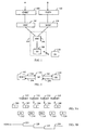
- Figures 3A and 3B show transmission and retransmission of packets using the stop and wait principle, which is known per se by a person skilled in the art.
- the stop and wait principle corresponds to the case where a transmitter is capable of memorizing only one packet at a time. The transmitter does not transmit a packet before it receives an ACK (Acknowledge) signal or a NACK (Not Acknowledge) signal from the receiver.
- ACK Acknowledge
- NACK Not Acknowledge
- the target SIR is lowered because of a successful transmission.
- the transmission power is adjusted according to the decreased target SIR leading to a lowered average transmission power (if the noise level has not increased).
- the receiver of the packet 302 transmits a NACK signal 314 requesting a retransmission of the faulty packet.
- the target SIR for retransmissions is adjusted differently from the first transmission of a packet. Hence, the target SIR is lowered according to formula (2) at moment 326.
- Target_SIR(1 st ) Target_SIR(master) - Step(1 st ), where the term Target_SIR(master) is the target SIR at moment 322.
- the transmission power at moment 328 is adjusted according to the decreased target SIR.
- the transmitter transmits the packet again (packet 304) at a lowered transmission power with respect to the interference level. However, the transmission fails again and the receiver transmits a NACK signal 316.
- the target SIR can be adjusted again, and in this example it is decreased at moment 330.
- the transmission power at moment 332 is adjusted according to the decreased target SIR.
- the transmitter transmits the packet once again (packet 306) at a lowered transmission power. This time the packet is correctly received and the receiver transmits an ACK signal 318.
- the target SIR is increased at moment 334 leading to an increased transmission power (relative to the interference) at moment 336 for the first transmission of a packet 308, the successful reception of which is acknowledged by an ACK signal 320.
- Figure 4 illustrates the communication in the case of the selective repeat scheme.
- both the transmitter and the receiver have buffer memories for storing packets.
- the first packet 400 is successfully transmitted, which is acknowledged by an ACK signal 414 from the receiver.
- the target SIR is adjusted at moment 430.
- the second packet 402 is transmitted, but as it fails, the receiver transmits a NACK signal 416.
- the target SIR is adjusted similarly to the prior art at moment 432, and the third packet 404 is transmitted successfully and acknowledged with an ACK signal 418 from the receiver.
- the target SIR at moment 434 is calculated using formula (2) such that the term Target_SIR(master) is the target SIR at moment 432.
- the retransmission fails, however, and the receiver transmits a NACK signal 420.
- the target SIR for the packet 408, which is the first transmission, is formed conventionally according to the prior art at moment 436. Since the transmission is successful, the receiver transmits an ACK signal 422.
- the target SIR for the packet 410 is formed by formula (2) such that the term Target_SIR(master) is the target SIR 436.
- Target_SIR(2 nd ) Target_SIR(master) - ⁇ (2 nd ), which lowers the average transmission power of the packet 410 in relation to interfe r-ence.
- This transmission leads to an ACK signal 424 from the receiver.
- the transmission of packets continues similarly with the packet 412, etc.
- the present solution lowers the absolute transmission power of the retransmission compared to the first transmission of a particular packet, if the channel keeps unchanged (no change, for example, in path loss, slow fading and fast fading). Since this is rarely the situation in a radio system, the transmission power depends on both the interference level and the transmission power of the first transmission of the packet, resulting usually in a lowered average transmission power.
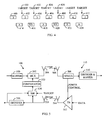
- Figure 5 illustrates a closed loop power control.
- the data for the user can be input from a buffer memory 500 to a multiplexer 502, which multiplexes the power control bits to the data stream in a base station 108.
- the buffer memory is not always needed.
- the data is encoded by a FEC code, such as a turbo code, and the data may also include information on the type of HARQ (type I HARQ, type II HARQ).
- the baseband signal with data and power control bits is spread by a CDMA spreading code and mixed with a desired carrier frequency (coding, type defining, spreading and mixing are not shown in Figure 5 ) in order to transmit the radio frequency signal from an antenna 504.
- An antenna 506 of a user terminal 110 receives the signal.
- the signal is mixed to a baseband signal and despead by a spreading code (despreading and mixing are not shown in Figure 5 ).
- the signal is demultiplexed in a demultiplexer 508, which separates data and power control bits.
- the data is fed to a block 510 to be decoded.
- the block 510 may include a buffer memory for storing a packet.
- the power control bits are fed to a power amplifier 512, which adjusts its amplification according to the power control bits.
- the power amplifier 512 amplifies the signal to be transmitted by the user terminal 110.
- the transmitter of the user terminal is basically similar to the transmitter of the base station.
- the signal is transmitted from an antenna 514, which may be the same as the antenna 506.
- the antenna 516 which may the same as the antenna 504, receives the signal which is mixed to a baseband signal and despead by a spreading code (despreading and mixing are not shown in Figure 5 ).
- the signal is then fed to a decoding block 518.
- the SIR measurement in the block 520 can be made before or after the decoding (either of the two arrows).
- the block 520 performs the SIR estimation for the despread control symbols.
- the SIR measurement is divided into a signal power measurement and an interference power measurement.
- the measurement is performed on the DPCCH channel (Dedicated Physical Control Channel).
- the measured SIR is compared with the target SIR received from the radio network controller in the block 522. Based on the comparison, the block 522 inputs the power control bits to the multiplexer 502.
- the power control bits may define a specific transmission power for each retransmission of a packet.
- a way to implement HARQ is to use chase combining where a retransmitted packet is similar to the originally transmitted packet. To further improve performance, it is also possible to use incremental redundancy (IR), where a retransmitted packet comprises new redundancy bits.
- IR incremental redundancy
- the receiving transceiver is equipped with a buffer memory in which faulty packets can be stored (in Figure 5 the block 510 includes the buffer memory). To operate like in Figure 4 the transmitter also needs a memory (in Figure 5 the block 500).
- FIG. 6 shows again the main steps of the presented method.
- step 600 at least two transceivers of the radio system communicate using a packet switched connection through a radio interface.
- step 602 the quality of the packet switched connection is measured.
- the power control system adjusts a target SIR based on the quality measured in step 604.
- a transceiver receiving packets transmits a request to retransmit at least one packet having failure in reception.
- step 608 a transceiver transmitting packets transmits each packet requested as a response to the request.
- step 610 the transmission power is controlled by setting a lower target SIR for retransmission of a packet than the target SIR for the first transmission of the corresponding packet.
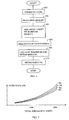
- Figure 7 shows simulation results of the use of the present solution.
- the user terminal moves 3 km/h
- data rate is 384 kbps with 1/3 turbo coding
- HARQ with chase combining is used and the maximum number of retransmissions is 2.
- Curve 700 represents a case where the failed transmission (first transmission or first retransmission) of a packet is not utilized in the combining.
- Curves 702 to 706 represent cases where the failed transmission of a packet is utilized in the combining.
- a retransmitted packet is transmitted using the same power as the first packet.
- a retransmitted packet transmitted is transmitted using 2 dB smaller target SIR value than the first packet.
- a retransmitted packet is transmitted using 5 dB smaller target SIR value than the first packet.
- the communication capacity increases. If the case represented by curve 700 is selected as a reference the case of curve 702 increases capacity by 5.1%, the case of curve 704 increases capacity by 13.30%, and the case of curve 706 increases capacity by 15.96%. Actually, the highest increase (16.41%) in capacity takes place close to the decrease of 4dB for the retransmission of a packet in this configuration.
- the transmission power of the dedicated control channel may also be lowered during a retransmission of a packet or between transmissions of packets in order to decrease interference. This is achieved by adjusting the target SIR value properly.
Abstract
Description
- The invention relates to a communication method and arrangement based on a packet switched connection in a radio system.
- It is vital to have power control of signals in a radio system. This is of a particular importance in a CDMA (Code Division Multiple Access) radio system, which is interference-limited. The main task of the power control in a CDMA radio system is to limit signal powers, and hence increase capacity by decreasing interference inside each cell.
- For example, in a WCDMA (Wide band CDMA) radio system the power control mechanism comprises an inner loop power control and an outer loop power control.
- The purpose of the inner loop power control is to eliminate rapid variations in the strength of a received signal caused by the radio channel.
- In the inner loop power control, a base station compares the SIR (Signal Interference Ratio) of the received signal to a target SIR. If the SIR of the received signal is below the target SIR, the base station transmits a signal commanding the user terminal to increase its transmission power. Correspondingly, if the SIR of the received signal is above the target SIR, the base station transmits a signal commanding the user terminal to decrease its transmission power.
- In the outer loop control a radio network controller (RNC) compares the quality of service to a target quality. The quality can be measured as, for instance, BER (Bit Error Rate), BLER (Block Error Rate), FER (Frame Error Rate), CRC (Cyclic Redundancy Check), soft information from the decoder, ratio of received bit energy and noise, etc. If the quality of service is below the target quality, the RNC commands the base station to increase its target SIR. Similarly, if the quality of service is above the target quality, the RNC commands the base station to decrease its target SIR.
- In radio systems utilizing packet-switched connection, the packets are usually protected against noise, fading and interference by channel coding, such as FEC (Forward Error correction Coding). In spite of protection, failure may occur in the reception of a packet, which can be compensated for by retransmission. The retransmission takes place when the receiving transceiver of packets requests the faulty packet to be repeated. This can be performed by an ARQ (Automatic Repeat Request) mechanism. In a receiver utilizing HARQ (Hybrid ARQ), the faulty packet and the retransmitted packet can be combined. The combining can be especially effective if different transmissions of the same packet are utilized in decoding.
- There are, however, problems related to the use of retransmission with power control, especially in the case of HARQ. When a packet is communicated unsuccessfully, the outer loop power control increases the target SIR, which unnecessarily leads to a higher transmission power during retransmission of the packet. The increased transmission power in relation to interference in turn decreases the capacity and service quality of the radio system.
- Document
US 2002/0042283 discloses a CDMA radio system using transmission power control based on SIR measurement. - An object of the invention is to provide an improved power control mechanism. According to an aspect of the invention, there is provided a communication method in a CDMA radio system using a transmission power control based on a SIR measurement, the method comprising: communicating between at least two transceivers of the radio system using a packet switched connection through a radio interface, measuring a quality of the packet switched connection, adjusting a target SIR based on the quality measured, transmitting, from a transceiver receiving packets, a request to retransmit at least one packet having failure in reception, retransmitting, from a transceiver transmitting packets, each packet requested as a response to the request. Moreover, the method comprises controlling a transmission power by setting a lower target SIR for retransmission of a packet than the target SIR for the first transmission of the corresponding packet.
- According to another aspect of the invention, there is provided a communication arrangement in a CDMA radio system using a transmission power control based on a SIR measurement, the arrangement comprising: at least two transceivers of the radio system being configured to communicate with a packet switched connection through a radio interface, means for measuring a quality of the packet switched connection, the arrangement is configured to adjust a target SIR based on the quality measured, a transceiver receiving packets is configured to transmit a request to retransmit in the case of failure in reception of at least one packet, a transceiver transmitting packets is configured to retransmit each packet requested as a response to the request. Moreover, the arrangement is configured to set a lower target SIR for retransmission of a packet than the target SIR for the first transmission of the corresponding packet.
- Preferred embodiments of the invention are described in the dependent claims.
- The invention provides several advantages. The present solution provides a specific way to control the transmission power of retransmissions and it improves the capacity of a cell by reducing interference.
- In the following, the invention will be described in greater detail with reference to the preferred embodiments and the accompanying drawings, in which
-
Figure 1 shows a radio system, -
Figure 2 illustrates power control, -
Figure 3A shows transmission and retransmission of packets according to the stop and wait principle, -
Figure 3B illustrates behaviour of transmission power in relation to transmission and retransmission inFigure 3A , -
Figure 4 shows transmission and retransmission of packets according to a selective repeat scheme, -
Figure 5 shows closed loop power control, -
Figure 6 shows a flow chart of the present method, and -
Figure 7 illustrates simulation results. - Let us first study
Figure 1 that illustrates the structure of a radio system. The radio system can be based on, for example, UMTS (Universal Mobile Telephone System) or WCDMA (Wide-band Code Division Multiple Access). - The core network may, for example, correspond to the combined structure of the GSM (Global System for Mobile Communications) and GPRS systems. The GSM network elements are responsible for the implementation of circuit-switched connections, and the GPRS network elements for the implementation of packet-switched connections, some of the network elements being, however, shared by both systems.
- A mobile services switching centre (MSC) 100 enables circuit-switched signalling in the radio system. A serving GPRS support node (SGSN) 101 in turn enables packet-switched signalling. All traffic in the radio system may be controlled by the MSC 100.
- The core network may have a
gateway unit 102, which represents a gateway mobile service switching centre (GMSC) for attending to the circuit-switched connections between the core network and external networks, such as a public land mobile network (PLMN) or a public switched telephone network (PSTN). A gateway GPRS support node (GGSN) 103 attends to the packet-switched connections between the core network and external networks, such as the Internet. - The MSC 100 and the SGSN are connected to a radio access network (RAN) 104, which may comprise at least one
base station controller 106 controlling at least onebase station 108. Thebase station controller 106 can also be called a radio network controller, and the base station can be called a node B. Auser terminal 110 communicates with at least onebase station 108 over a radio interface. - The
user terminal 110 can communicate with thebase station 108 using a GPRS method. Data in packets contain address and control data in addition to the actual traffic data. Several connections may employ the same transmission channel simultaneously. A packet-switching method is suitable for data transmission where the data to be transmitted is generated in bursts. In such a case, it is not necessary to allocate a data link for the entire duration of transmission but only for the time it takes to transmit the packets. This reduces costs and saves capacity considerably during both the set-up and use of the network. -
Figure 2 represents both outer and inner loop power control. When theuser terminal 110 transmits asignal 200, such as a packet, to abase station 108, thebase station 108 forms a SIR (Signal-to-Interference Ratio) estimate of the received signal. The base station compares the SIR estimate to a target SIR, and transmits asignal 202 with a command, which depends on the comparison. If the value of the SIR estimate is smaller than the value of the target SIR, thebase station 108 commands theuser terminal 110 to increase its transmission power. If, on the other hand, the SIR estimate is higher than the target SIR, the base station commands the user terminal to decrease its transmission power. - The
base station 108 sends the radio network controller 106 asignal 204 having information on the quality of the connection. The quality can be the quality of service and the information can indicate frame reliability, which can be based on the use of a reliability indicator. The reliability indicator can be CRC (Cyclic Redundancy Check), estimated BER, soft information from a decoder, Eb/N0, etc. - The target SIR can be changed by an outer-loop power control algorithm which in prior art can be expressed as follows:

- The
radio network controller 106 in turn sends the base station 108 asignal 206 having effect on the target SIR according to the formula (1). If the value of the quality of service is below a quality target value, which is true in the case of failure in reception of a packet, theradio network controller 108 increases the target SIR in thebase station 108. As a result of this, the average transmission power of a retransmission of a packet is higher than during the first transmission of the packet, assuming the interference level is the same. The interference is also considered to include noise. If the value of the quality of service is above a target value, theradio network controller 108 decreases the target SIR in thebase station 108, which lowers the average transmission power with respect to interference. This takes place when a packet is received successfully. - According to the present solution, the target SIR can be defined by an outer-loop power control algorithm as follows:

-
Figures 3A and 3B show transmission and retransmission of packets using the stop and wait principle, which is known per se by a person skilled in the art. The stop and wait principle corresponds to the case where a transmitter is capable of memorizing only one packet at a time. The transmitter does not transmit a packet before it receives an ACK (Acknowledge) signal or a NACK (Not Acknowledge) signal from the receiver. - After the
first packet 300 is transmitted from the transmitter, it is acknowledged as successfully received by anACK signal 312 from the receiver. Atmoment 322 before transmitting anew packet 302 the target SIR is lowered because of a successful transmission. Right after that atmoment 324 the transmission power is adjusted according to the decreased target SIR leading to a lowered average transmission power (if the noise level has not increased). Then thesecond packet 302 is transmitted but because there is a failure in reception, the receiver of thepacket 302 transmits aNACK signal 314 requesting a retransmission of the faulty packet. According to the present solution, the target SIR for retransmissions is adjusted differently from the first transmission of a packet. Hence, the target SIR is lowered according to formula (2) atmoment 326. The target SIR for the first retransmission becomes Target_SIR(1 st) = Target_SIR(master) - Step(1 st), where the term Target_SIR(master) is the target SIR atmoment 322. The transmission power atmoment 328 is adjusted according to the decreased target SIR. The transmitter transmits the packet again (packet 304) at a lowered transmission power with respect to the interference level. However, the transmission fails again and the receiver transmits aNACK signal 316. The target SIR can be adjusted again, and in this example it is decreased atmoment 330. The target SIR becomes Target_SIR(2nd) = Target_SIR(master) - Step(2nd), where the term Target_SIR(master) is the target SIR 322 (the target SIR for the first transmission of a packet). The transmission power atmoment 332 is adjusted according to the decreased target SIR. The transmitter transmits the packet once again (packet 306) at a lowered transmission power. This time the packet is correctly received and the receiver transmits anACK signal 318. The target SIR is increased atmoment 334 leading to an increased transmission power (relative to the interference) atmoment 336 for the first transmission of apacket 308, the successful reception of which is acknowledged by anACK signal 320. -
Figure 4 illustrates the communication in the case of the selective repeat scheme. In this case both the transmitter and the receiver have buffer memories for storing packets. Thefirst packet 400 is successfully transmitted, which is acknowledged by anACK signal 414 from the receiver. The target SIR is adjusted atmoment 430. Thesecond packet 402 is transmitted, but as it fails, the receiver transmits aNACK signal 416. The target SIR is adjusted similarly to the prior art atmoment 432, and thethird packet 404 is transmitted successfully and acknowledged with anACK signal 418 from the receiver. The target SIR atmoment 434 is calculated using formula (2) such that the term Target_SIR(master) is the target SIR atmoment 432. The target SIR for the first retransmission becomes Target_SIR(1st) = Target_SIR(master) - Δ(1st), which lowers the average transmission power of thepacket 406 in relation to interference. The retransmission fails, however, and the receiver transmits aNACK signal 420. The target SIR for thepacket 408, which is the first transmission, is formed conventionally according to the prior art atmoment 436. Since the transmission is successful, the receiver transmits anACK signal 422. The target SIR for thepacket 410 is formed by formula (2) such that the term Target_SIR(master) is thetarget SIR 436. The target SIR for the second retransmission becomes Target_SIR(2nd) = Target_SIR(master) - Δ(2nd), which lowers the average transmission power of thepacket 410 in relation to interfe r-ence. This transmission leads to anACK signal 424 from the receiver. The transmission of packets continues similarly with thepacket 412, etc. - The present solution lowers the absolute transmission power of the retransmission compared to the first transmission of a particular packet, if the channel keeps unchanged (no change, for example, in path loss, slow fading and fast fading). Since this is rarely the situation in a radio system, the transmission power depends on both the interference level and the transmission power of the first transmission of the packet, resulting usually in a lowered average transmission power.
-
Figure 5 illustrates a closed loop power control. The data for the user can be input from abuffer memory 500 to amultiplexer 502, which multiplexes the power control bits to the data stream in abase station 108. The buffer memory is not always needed. The data is encoded by a FEC code, such as a turbo code, and the data may also include information on the type of HARQ (type I HARQ, type II HARQ). The baseband signal with data and power control bits is spread by a CDMA spreading code and mixed with a desired carrier frequency (coding, type defining, spreading and mixing are not shown inFigure 5 ) in order to transmit the radio frequency signal from anantenna 504. Anantenna 506 of auser terminal 110 receives the signal. The signal is mixed to a baseband signal and despead by a spreading code (despreading and mixing are not shown inFigure 5 ). The signal is demultiplexed in ademultiplexer 508, which separates data and power control bits. The data is fed to ablock 510 to be decoded. Theblock 510 may include a buffer memory for storing a packet. The power control bits are fed to apower amplifier 512, which adjusts its amplification according to the power control bits. Thepower amplifier 512 amplifies the signal to be transmitted by theuser terminal 110. The transmitter of the user terminal is basically similar to the transmitter of the base station. The signal is transmitted from anantenna 514, which may be the same as theantenna 506. Theantenna 516, which may the same as theantenna 504, receives the signal which is mixed to a baseband signal and despead by a spreading code (despreading and mixing are not shown inFigure 5 ). The signal is then fed to adecoding block 518. The SIR measurement in theblock 520 can be made before or after the decoding (either of the two arrows). Theblock 520 performs the SIR estimation for the despread control symbols. Generally, the SIR measurement is divided into a signal power measurement and an interference power measurement. The measurement is performed on the DPCCH channel (Dedicated Physical Control Channel). The measured SIR is compared with the target SIR received from the radio network controller in theblock 522. Based on the comparison, theblock 522 inputs the power control bits to themultiplexer 502. - Instead of changing the transmission a step up or down, the power control bits may define a specific transmission power for each retransmission of a packet.
- A way to implement HARQ is to use chase combining where a retransmitted packet is similar to the originally transmitted packet. To further improve performance, it is also possible to use incremental redundancy (IR), where a retransmitted packet comprises new redundancy bits. To utilize HARQ, the receiving transceiver is equipped with a buffer memory in which faulty packets can be stored (in
Figure 5 theblock 510 includes the buffer memory). To operate like inFigure 4 the transmitter also needs a memory (inFigure 5 the block 500). -
Figure 6 shows again the main steps of the presented method. Instep 600 at least two transceivers of the radio system communicate using a packet switched connection through a radio interface. Instep 602 the quality of the packet switched connection is measured. The power control system adjusts a target SIR based on the quality measured instep 604. In the step 606 a transceiver receiving packets transmits a request to retransmit at least one packet having failure in reception. In step 608 a transceiver transmitting packets transmits each packet requested as a response to the request. Instep 610 the transmission power is controlled by setting a lower target SIR for retransmission of a packet than the target SIR for the first transmission of the corresponding packet. -
Figure 7 shows simulation results of the use of the present solution. In this example it is assumed that the user terminal moves 3 km/h, data rate is 384 kbps with 1/3 turbo coding, HARQ with chase combining is used and the maximum number of retransmissions is 2.Curve 700 represents a case where the failed transmission (first transmission or first retransmission) of a packet is not utilized in the combining. Curves 702 to 706 represent cases where the failed transmission of a packet is utilized in the combining. In curve 702 a retransmitted packet is transmitted using the same power as the first packet. In curve 704 a retransmitted packet transmitted is transmitted using 2 dB smaller target SIR value than the first packet. In curve 706 a retransmitted packet is transmitted using 5 dB smaller target SIR value than the first packet. With the decreasing power of the second transmission of a packet, the communication capacity increases. If the case represented bycurve 700 is selected as a reference the case of curve 702 increases capacity by 5.1%, the case ofcurve 704 increases capacity by 13.30%, and the case ofcurve 706 increases capacity by 15.96%. Actually, the highest increase (16.41%) in capacity takes place close to the decrease of 4dB for the retransmission of a packet in this configuration. There is an optimum decrease in the target SIR value of the second transmission that has the maximum increase in capacity. However, a decrease in the target SIR value of the retransmission, particularly with respect to interference, usually tends to increase capacity. - According to the present solution, the transmission power of the dedicated control channel may also be lowered during a retransmission of a packet or between transmissions of packets in order to decrease interference. This is achieved by adjusting the target SIR value properly.
- Even though the invention is described above with reference to an example according to the accompanying drawings, it is clear that the invention is not restricted thereto but it can be modified in several ways within the scope of the appended claims.
Claims (10)
- A communication method in a CDMA radio system using a transmission power control based on a SIR measurement, the method comprising:communicating (600) between at least two transceivers (108 to 110) of the radio system using a packet switched connection through a radio interface,measuring (602) a quality of the packet switched connection,adjusting (604) a target SIR based on the quality measured,transmitting (606), from a transceiver (110) receiving packets, a request to retransmit at least one packet having failure in reception,retransmitting (608), from a transceiver (108) transmitting packets, each packet requested as a response to the request, characterized bycontrolling (610) a transmission power by setting a lower target SIR for retransmission of a packet than the target SIR for the first transmission of the corresponding packet.
- The method of claim 1, characterized by further comprising defining a specific target SIR for each retransmission of a packet.
- The method of claim 1, characterized by further comprising setting a lower target SIR for the dedicated control channel between transmissions of packets than during the packets.
- The method of claim 1, characterized by further comprising transmitting, from the transceiver receiving packets, a transmission strength at which to retransmit at least the one packet having failure in reception.
- The method of claim 1, characterized by further comprising setting the lower target SIR according the algorithm:

where Target_SIR(Nth) means the SIR of the Nth retransmission of a packet, Target_SIR(master) means the target SIR of the first transmission of a packet, Step(Nth) means the amount in decrease in the transmission power of the retransmission, and N is an ordinal number denoting the index of retransmission. - A communication arrangement in a CDMA radio system using a transmission power control based on a SIR measurement, the arrangement comprising:at least two transceivers (108 to 110) of the radio system being configured to communicate with a packet switched connection through a radio i n-terface,means (520) for measuring a quality of the packet switched connection,the arrangement is configured to adjust a target SIR based on the quality measured,a transceiver (110) receiving packets is configured to transmit a request to retransmit in the case of failure in reception of at least one packet,a transceiver (108) transmitting packets is configured to retransmit each packet requested as a response to the request, characterized inthatthe arrangement is configured to set a lower target SIR for retransmission of a packet than the target SIR for the first transmission of the corresponding packet.
- The arrangement of claim 6, characterized in that the arrangement is configured to define a specific target SIR for each retransmission of a packet.
- The arrangement of claim 6, characterized in that the arrangement is configured to set a lower target SIR for the dedicated control channel between transmissions of packets than during the packets.
- The arrangement of claim 6, characterized in that transmitter receiving packets is configured to transmit a transmission strength at which to retransmit at least the one packet having failure in reception.
- The arrangement of claim 6, characterized in that the arrangement is configured to set the lower target SIR according to the algorithm:

where Target_SIR(Nth) means the SIR of the Nth retransmission of a packet, Target_SIR(master) means the target SIR of the first transmission of a packet, Step(Nth) means the amount in decrease in the transmission power of the retransmission, and N is an ordinal number denoting the index of retransmission.
Applications Claiming Priority (2)
| Application Number | Priority Date | Filing Date | Title |
|---|---|---|---|
| FI20031176 | 2003-08-21 | ||
| FI20031176 | 2003-08-21 |
Publications (2)
| Publication Number | Publication Date |
|---|---|
| EP1508978A1 EP1508978A1 (en) | 2005-02-23 |
| EP1508978B1 true EP1508978B1 (en) | 2008-02-13 |
Family
ID=27838860
Family Applications (1)
| Application Number | Title | Priority Date | Filing Date |
|---|---|---|---|
| EP04103933A Not-in-force EP1508978B1 (en) | 2003-08-21 | 2004-08-17 | Power control method and arrangement for a packet switched radio system |
Country Status (5)
| Country | Link |
|---|---|
| US (1) | US7352725B2 (en) |
| EP (1) | EP1508978B1 (en) |
| CN (1) | CN100341258C (en) |
| AT (1) | ATE386373T1 (en) |
| DE (1) | DE602004011707T2 (en) |
Families Citing this family (20)
| Publication number | Priority date | Publication date | Assignee | Title |
|---|---|---|---|---|
| US7190749B2 (en) * | 2001-06-06 | 2007-03-13 | Qualcomm Incorporated | Method and apparatus for canceling pilot interference in a wireless communication system |
| US8611311B2 (en) * | 2001-06-06 | 2013-12-17 | Qualcomm Incorporated | Method and apparatus for canceling pilot interference in a wireless communication system |
| JP3679089B2 (en) * | 2002-11-20 | 2005-08-03 | 松下電器産業株式会社 | Base station apparatus and retransmission packet transmission power control method |
| CN1617479A (en) * | 2003-11-14 | 2005-05-18 | 北京三星通信技术研究有限公司 | Method for supporting pilot frequency enhancement in up line special channel enhancement in broad band CDMA |
| JP2005277570A (en) * | 2004-03-23 | 2005-10-06 | Fujitsu Ltd | Transmitter, receiver, and retransmission control method |
| FI20045244A0 (en) * | 2004-06-28 | 2004-06-28 | Nokia Corp | Transmit Power Control |
| CN101061648B (en) * | 2004-11-19 | 2012-09-26 | 株式会社Ntt都科摩 | Mobile communication method and mobile station |
| US7706745B2 (en) * | 2004-12-03 | 2010-04-27 | M&Fc Holding, Llc | Method, system, apparatus, and computer program product for communications relay |
| US8099123B2 (en) * | 2004-12-23 | 2012-01-17 | Qualcomm Incorporated | Adaptation of transmit subchannel gains in a system with interference cancellation |
| US8422955B2 (en) * | 2004-12-23 | 2013-04-16 | Qualcomm Incorporated | Channel estimation for interference cancellation |
| US8406695B2 (en) * | 2004-12-23 | 2013-03-26 | Qualcomm Incorporated | Joint interference cancellation of pilot, overhead and traffic channels |
| US8442441B2 (en) * | 2004-12-23 | 2013-05-14 | Qualcomm Incorporated | Traffic interference cancellation |
| KR100927368B1 (en) * | 2005-03-18 | 2009-11-19 | 가부시키가이샤 엔.티.티.도코모 | Transmission power control method, mobile station, radio base station and radio network control station |
| US8472877B2 (en) * | 2005-10-24 | 2013-06-25 | Qualcomm Incorporated | Iterative interference cancellation system and method |
| US8385388B2 (en) * | 2005-12-06 | 2013-02-26 | Qualcomm Incorporated | Method and system for signal reconstruction from spatially and temporally correlated received samples |
| JP4589250B2 (en) | 2006-02-21 | 2010-12-01 | 富士通株式会社 | Power control apparatus in wireless communication system |
| JP4589249B2 (en) * | 2006-02-21 | 2010-12-01 | 富士通株式会社 | Power control apparatus in wireless communication system |
| GB0712701D0 (en) * | 2007-06-29 | 2007-08-08 | Inc Icera | Processing transmission in a wireless communication system |
| US8059759B2 (en) * | 2008-05-19 | 2011-11-15 | Qualcomm Incorporated | Methods and systems for initial FCH processing |
| CN103002557B (en) * | 2011-09-13 | 2016-02-17 | 中磊电子(苏州)有限公司 | Poewr control method and wireless telecommunication system |
Family Cites Families (9)
| Publication number | Priority date | Publication date | Assignee | Title |
|---|---|---|---|---|
| FI103541B (en) * | 1997-04-28 | 1999-07-15 | Nokia Mobile Phones Ltd | A method for transferring packet switched data from a mobile system |
| US6101168A (en) * | 1997-11-13 | 2000-08-08 | Qualcomm Inc. | Method and apparatus for time efficient retransmission using symbol accumulation |
| US6317854B1 (en) * | 1999-05-14 | 2001-11-13 | Nokia Corporation | Apparatus, and associated method, for selecting retransmission of packet data |
| US6507572B1 (en) * | 1999-06-11 | 2003-01-14 | Lucent Technologies Inc. | Primary transfer for simplex mode forward-link high-speed packet data services in CDMA systems |
| US6711150B1 (en) | 2000-04-07 | 2004-03-23 | Telefonktiebolaget L.M. Ericsson | System and method for data burst communications in a CDMA network |
| EP1238476B1 (en) | 2000-10-09 | 2011-12-14 | Koninklijke Philips Electronics N.V. | Method and apparatus for the communication of information with power control |
| DE60135430D1 (en) * | 2000-11-17 | 2008-10-02 | Lg Electronics Inc | Method for blind connection adaptation using acknowledgment messages in ARQ transmission system |
| SE0101281D0 (en) * | 2001-04-06 | 2001-04-06 | Ericsson Telefon Ab L M | Method and system of link control |
| CN1151620C (en) | 2002-04-28 | 2004-05-26 | 武汉汉网高技术有限公司 | Multiuser downstream grouping transmission quality control method for CDMA communication system |
-
2003
- 2003-10-15 US US10/684,825 patent/US7352725B2/en not_active Expired - Fee Related
-
2004
- 2004-08-04 CN CNB2004100558480A patent/CN100341258C/en not_active Expired - Fee Related
- 2004-08-17 AT AT04103933T patent/ATE386373T1/en not_active IP Right Cessation
- 2004-08-17 EP EP04103933A patent/EP1508978B1/en not_active Not-in-force
- 2004-08-17 DE DE602004011707T patent/DE602004011707T2/en active Active
Also Published As
| Publication number | Publication date |
|---|---|
| US7352725B2 (en) | 2008-04-01 |
| ATE386373T1 (en) | 2008-03-15 |
| CN1585293A (en) | 2005-02-23 |
| CN100341258C (en) | 2007-10-03 |
| DE602004011707T2 (en) | 2009-01-29 |
| US20050041626A1 (en) | 2005-02-24 |
| DE602004011707D1 (en) | 2008-03-27 |
| EP1508978A1 (en) | 2005-02-23 |
Similar Documents
| Publication | Publication Date | Title |
|---|---|---|
| EP1508978B1 (en) | Power control method and arrangement for a packet switched radio system | |
| EP1522154B1 (en) | Adaptive gain adjustment control with feedback | |
| EP1645051B1 (en) | Secondary link power control in a wireless communication network | |
| KR101067281B1 (en) | Mobile communication terminal and method for controlling transmission power | |
| EP1516440B1 (en) | Outer loop uplink power control during link imbalance | |
| US7372834B2 (en) | Method of controlling transmission power of retransmission packet and mobile terminal using the same | |
| EP1774676B1 (en) | Outer loop power control with transport block diversity transmission | |
| US20090290559A1 (en) | Method and apparatus for harq autonomous retransmissions | |
| US7573860B2 (en) | Method, device and system for determining a transmission power for ARQ related re-transmissions | |
| US20020028691A1 (en) | Method for the communication of information and apparatus employing the method | |
| US20060268789A1 (en) | Radio resource control in HSUPA system | |
| US20090150738A1 (en) | Data communication apparatus, data receiving apparatus, data transmitting apparatus, and retransmission control method | |
| US20050288053A1 (en) | Transmission power control | |
| US20020027897A1 (en) | Method for the communication of information and apparatus employing the method | |
| KR20030085072A (en) | Method and apparatus for power control in a wireless communication system | |
| US7653857B2 (en) | Power control of packet data transmission in cellular network | |
| CN100384099C (en) | Power controlling method for uplink high-speed special physical control channel | |
| EP1220472A1 (en) | Method and arrangement for implementing power control | |
| KR100763373B1 (en) | Method for power control of transmitting signal in mobile communication system | |
| KR20040071554A (en) | Power controlling apparatus and method of reverse link in mobile communication system by using h-arq |
Legal Events
| Date | Code | Title | Description |
|---|---|---|---|
| PUAI | Public reference made under article 153(3) epc to a published international application that has entered the european phase |
Free format text: ORIGINAL CODE: 0009012 |
|
| AK | Designated contracting states |
Kind code of ref document: A1 Designated state(s): AT BE BG CH CY CZ DE DK EE ES FI FR GB GR HU IE IT LI LU MC NL PL PT RO SE SI SK TR |
|
| AX | Request for extension of the european patent |
Extension state: AL HR LT LV MK |
|
| 17P | Request for examination filed |
Effective date: 20050801 |
|
| AKX | Designation fees paid |
Designated state(s): AT BE BG CH CY CZ DE DK EE ES FI FR GB GR HU IE IT LI LU MC NL PL PT RO SE SI SK TR |
|
| GRAP | Despatch of communication of intention to grant a patent |
Free format text: ORIGINAL CODE: EPIDOSNIGR1 |
|
| GRAS | Grant fee paid |
Free format text: ORIGINAL CODE: EPIDOSNIGR3 |
|
| GRAA | (expected) grant |
Free format text: ORIGINAL CODE: 0009210 |
|
| AK | Designated contracting states |
Kind code of ref document: B1 Designated state(s): AT BE BG CH CY CZ DE DK EE ES FI FR GB GR HU IE IT LI LU MC NL PL PT RO SE SI SK TR |
|
| RAP1 | Party data changed (applicant data changed or rights of an application transferred) |
Owner name: NOKIA SIEMENS NETWORKS OY |
|
| REG | Reference to a national code |
Ref country code: GB Ref legal event code: FG4D |
|
| REG | Reference to a national code |
Ref country code: CH Ref legal event code: EP |
|
| REG | Reference to a national code |
Ref country code: IE Ref legal event code: FG4D |
|
| REF | Corresponds to: |
Ref document number: 602004011707 Country of ref document: DE Date of ref document: 20080327 Kind code of ref document: P |
|
| PG25 | Lapsed in a contracting state [announced via postgrant information from national office to epo] |
Ref country code: FI Free format text: LAPSE BECAUSE OF FAILURE TO SUBMIT A TRANSLATION OF THE DESCRIPTION OR TO PAY THE FEE WITHIN THE PRESCRIBED TIME-LIMIT Effective date: 20080213 Ref country code: ES Free format text: LAPSE BECAUSE OF FAILURE TO SUBMIT A TRANSLATION OF THE DESCRIPTION OR TO PAY THE FEE WITHIN THE PRESCRIBED TIME-LIMIT Effective date: 20080524 |
|
| NLV1 | Nl: lapsed or annulled due to failure to fulfill the requirements of art. 29p and 29m of the patents act | ||
| ET | Fr: translation filed | ||
| PG25 | Lapsed in a contracting state [announced via postgrant information from national office to epo] |
Ref country code: AT Free format text: LAPSE BECAUSE OF FAILURE TO SUBMIT A TRANSLATION OF THE DESCRIPTION OR TO PAY THE FEE WITHIN THE PRESCRIBED TIME-LIMIT Effective date: 20080213 |
|
| PG25 | Lapsed in a contracting state [announced via postgrant information from national office to epo] |
Ref country code: PL Free format text: LAPSE BECAUSE OF FAILURE TO SUBMIT A TRANSLATION OF THE DESCRIPTION OR TO PAY THE FEE WITHIN THE PRESCRIBED TIME-LIMIT Effective date: 20080213 Ref country code: SI Free format text: LAPSE BECAUSE OF FAILURE TO SUBMIT A TRANSLATION OF THE DESCRIPTION OR TO PAY THE FEE WITHIN THE PRESCRIBED TIME-LIMIT Effective date: 20080213 Ref country code: BE Free format text: LAPSE BECAUSE OF FAILURE TO SUBMIT A TRANSLATION OF THE DESCRIPTION OR TO PAY THE FEE WITHIN THE PRESCRIBED TIME-LIMIT Effective date: 20080213 |
|
| PG25 | Lapsed in a contracting state [announced via postgrant information from national office to epo] |
Ref country code: SK Free format text: LAPSE BECAUSE OF FAILURE TO SUBMIT A TRANSLATION OF THE DESCRIPTION OR TO PAY THE FEE WITHIN THE PRESCRIBED TIME-LIMIT Effective date: 20080213 Ref country code: SE Free format text: LAPSE BECAUSE OF FAILURE TO SUBMIT A TRANSLATION OF THE DESCRIPTION OR TO PAY THE FEE WITHIN THE PRESCRIBED TIME-LIMIT Effective date: 20080513 Ref country code: CZ Free format text: LAPSE BECAUSE OF FAILURE TO SUBMIT A TRANSLATION OF THE DESCRIPTION OR TO PAY THE FEE WITHIN THE PRESCRIBED TIME-LIMIT Effective date: 20080213 Ref country code: DK Free format text: LAPSE BECAUSE OF FAILURE TO SUBMIT A TRANSLATION OF THE DESCRIPTION OR TO PAY THE FEE WITHIN THE PRESCRIBED TIME-LIMIT Effective date: 20080213 Ref country code: NL Free format text: LAPSE BECAUSE OF FAILURE TO SUBMIT A TRANSLATION OF THE DESCRIPTION OR TO PAY THE FEE WITHIN THE PRESCRIBED TIME-LIMIT Effective date: 20080213 Ref country code: PT Free format text: LAPSE BECAUSE OF FAILURE TO SUBMIT A TRANSLATION OF THE DESCRIPTION OR TO PAY THE FEE WITHIN THE PRESCRIBED TIME-LIMIT Effective date: 20080714 |
|
| PG25 | Lapsed in a contracting state [announced via postgrant information from national office to epo] |
Ref country code: RO Free format text: LAPSE BECAUSE OF FAILURE TO SUBMIT A TRANSLATION OF THE DESCRIPTION OR TO PAY THE FEE WITHIN THE PRESCRIBED TIME-LIMIT Effective date: 20080213 |
|
| PGFP | Annual fee paid to national office [announced via postgrant information from national office to epo] |
Ref country code: FR Payment date: 20080813 Year of fee payment: 5 |
|
| PLBE | No opposition filed within time limit |
Free format text: ORIGINAL CODE: 0009261 |
|
| STAA | Information on the status of an ep patent application or granted ep patent |
Free format text: STATUS: NO OPPOSITION FILED WITHIN TIME LIMIT |
|
| 26N | No opposition filed |
Effective date: 20081114 |
|
| PG25 | Lapsed in a contracting state [announced via postgrant information from national office to epo] |
Ref country code: MC Free format text: LAPSE BECAUSE OF NON-PAYMENT OF DUE FEES Effective date: 20080831 |
|
| REG | Reference to a national code |
Ref country code: CH Ref legal event code: PL |
|
| PG25 | Lapsed in a contracting state [announced via postgrant information from national office to epo] |
Ref country code: EE Free format text: LAPSE BECAUSE OF FAILURE TO SUBMIT A TRANSLATION OF THE DESCRIPTION OR TO PAY THE FEE WITHIN THE PRESCRIBED TIME-LIMIT Effective date: 20080213 Ref country code: BG Free format text: LAPSE BECAUSE OF FAILURE TO SUBMIT A TRANSLATION OF THE DESCRIPTION OR TO PAY THE FEE WITHIN THE PRESCRIBED TIME-LIMIT Effective date: 20080513 |
|
| PG25 | Lapsed in a contracting state [announced via postgrant information from national office to epo] |
Ref country code: CH Free format text: LAPSE BECAUSE OF NON-PAYMENT OF DUE FEES Effective date: 20080831 Ref country code: LI Free format text: LAPSE BECAUSE OF NON-PAYMENT OF DUE FEES Effective date: 20080831 |
|
| PG25 | Lapsed in a contracting state [announced via postgrant information from national office to epo] |
Ref country code: IE Free format text: LAPSE BECAUSE OF NON-PAYMENT OF DUE FEES Effective date: 20080818 Ref country code: CY Free format text: LAPSE BECAUSE OF FAILURE TO SUBMIT A TRANSLATION OF THE DESCRIPTION OR TO PAY THE FEE WITHIN THE PRESCRIBED TIME-LIMIT Effective date: 20080213 |
|
| PGFP | Annual fee paid to national office [announced via postgrant information from national office to epo] |
Ref country code: IT Payment date: 20090819 Year of fee payment: 6 |
|
| REG | Reference to a national code |
Ref country code: FR Ref legal event code: ST Effective date: 20100430 |
|
| PG25 | Lapsed in a contracting state [announced via postgrant information from national office to epo] |
Ref country code: FR Free format text: LAPSE BECAUSE OF NON-PAYMENT OF DUE FEES Effective date: 20090831 Ref country code: HU Free format text: LAPSE BECAUSE OF FAILURE TO SUBMIT A TRANSLATION OF THE DESCRIPTION OR TO PAY THE FEE WITHIN THE PRESCRIBED TIME-LIMIT Effective date: 20080814 Ref country code: LU Free format text: LAPSE BECAUSE OF NON-PAYMENT OF DUE FEES Effective date: 20080817 |
|
| PG25 | Lapsed in a contracting state [announced via postgrant information from national office to epo] |
Ref country code: TR Free format text: LAPSE BECAUSE OF FAILURE TO SUBMIT A TRANSLATION OF THE DESCRIPTION OR TO PAY THE FEE WITHIN THE PRESCRIBED TIME-LIMIT Effective date: 20080213 |
|
| PG25 | Lapsed in a contracting state [announced via postgrant information from national office to epo] |
Ref country code: GR Free format text: LAPSE BECAUSE OF FAILURE TO SUBMIT A TRANSLATION OF THE DESCRIPTION OR TO PAY THE FEE WITHIN THE PRESCRIBED TIME-LIMIT Effective date: 20080514 |
|
| PG25 | Lapsed in a contracting state [announced via postgrant information from national office to epo] |
Ref country code: IT Free format text: LAPSE BECAUSE OF NON-PAYMENT OF DUE FEES Effective date: 20100817 |
|
| REG | Reference to a national code |
Ref country code: DE Ref legal event code: R082 Ref document number: 602004011707 Country of ref document: DE Representative=s name: SAMSON & PARTNER, PATENTANWAELTE, DE |
|
| REG | Reference to a national code |
Ref country code: DE Ref legal event code: R082 Ref document number: 602004011707 Country of ref document: DE Representative=s name: SAMSON & PARTNER, PATENTANWAELTE, DE Effective date: 20140521 Ref country code: DE Ref legal event code: R081 Ref document number: 602004011707 Country of ref document: DE Owner name: NOKIA SOLUTIONS AND NETWORKS OY, FI Free format text: FORMER OWNER: NOKIA SIEMENS NETWORKS OY, ESPOO, FI Effective date: 20140521 Ref country code: DE Ref legal event code: R082 Ref document number: 602004011707 Country of ref document: DE Representative=s name: SAMSON & PARTNER PATENTANWAELTE MBB, DE Effective date: 20140521 |
|
| PGFP | Annual fee paid to national office [announced via postgrant information from national office to epo] |
Ref country code: DE Payment date: 20140821 Year of fee payment: 11 |
|
| PGFP | Annual fee paid to national office [announced via postgrant information from national office to epo] |
Ref country code: GB Payment date: 20140820 Year of fee payment: 11 |
|
| REG | Reference to a national code |
Ref country code: DE Ref legal event code: R119 Ref document number: 602004011707 Country of ref document: DE |
|
| GBPC | Gb: european patent ceased through non-payment of renewal fee |
Effective date: 20150817 |
|
| PG25 | Lapsed in a contracting state [announced via postgrant information from national office to epo] |
Ref country code: GB Free format text: LAPSE BECAUSE OF NON-PAYMENT OF DUE FEES Effective date: 20150817 Ref country code: DE Free format text: LAPSE BECAUSE OF NON-PAYMENT OF DUE FEES Effective date: 20160301 |