EP1508828A1 - Photographic lens - Google Patents
Photographic lens Download PDFInfo
- Publication number
- EP1508828A1 EP1508828A1 EP04254728A EP04254728A EP1508828A1 EP 1508828 A1 EP1508828 A1 EP 1508828A1 EP 04254728 A EP04254728 A EP 04254728A EP 04254728 A EP04254728 A EP 04254728A EP 1508828 A1 EP1508828 A1 EP 1508828A1
- Authority
- EP
- European Patent Office
- Prior art keywords
- lens
- lens element
- focal length
- photographic
- stop
- Prior art date
- Legal status (The legal status is an assumption and is not a legal conclusion. Google has not performed a legal analysis and makes no representation as to the accuracy of the status listed.)
- Granted
Links
- 230000005499 meniscus Effects 0.000 claims abstract description 5
- 230000004075 alteration Effects 0.000 description 17
- 230000035945 sensitivity Effects 0.000 description 10
- 238000010586 diagram Methods 0.000 description 9
- 238000004519 manufacturing process Methods 0.000 description 6
- 125000006850 spacer group Chemical group 0.000 description 6
- 230000003287 optical effect Effects 0.000 description 3
- 239000006185 dispersion Substances 0.000 description 2
- 229920003023 plastic Polymers 0.000 description 2
- 239000004033 plastic Substances 0.000 description 2
- 230000000903 blocking effect Effects 0.000 description 1
- 230000006866 deterioration Effects 0.000 description 1
- 230000000694 effects Effects 0.000 description 1
- 238000005375 photometry Methods 0.000 description 1
- 238000004804 winding Methods 0.000 description 1
Images



Classifications
-
- G—PHYSICS
- G02—OPTICS
- G02B—OPTICAL ELEMENTS, SYSTEMS OR APPARATUS
- G02B13/00—Optical objectives specially designed for the purposes specified below
- G02B13/001—Miniaturised objectives for electronic devices, e.g. portable telephones, webcams, PDAs, small digital cameras
- G02B13/0015—Miniaturised objectives for electronic devices, e.g. portable telephones, webcams, PDAs, small digital cameras characterised by the lens design
- G02B13/002—Miniaturised objectives for electronic devices, e.g. portable telephones, webcams, PDAs, small digital cameras characterised by the lens design having at least one aspherical surface
- G02B13/003—Miniaturised objectives for electronic devices, e.g. portable telephones, webcams, PDAs, small digital cameras characterised by the lens design having at least one aspherical surface having two lenses
-
- G—PHYSICS
- G02—OPTICS
- G02B—OPTICAL ELEMENTS, SYSTEMS OR APPARATUS
- G02B13/00—Optical objectives specially designed for the purposes specified below
- G02B13/18—Optical objectives specially designed for the purposes specified below with lenses having one or more non-spherical faces, e.g. for reducing geometrical aberration
-
- G—PHYSICS
- G02—OPTICS
- G02B—OPTICAL ELEMENTS, SYSTEMS OR APPARATUS
- G02B9/00—Optical objectives characterised both by the number of the components and their arrangements according to their sign, i.e. + or -
- G02B9/04—Optical objectives characterised both by the number of the components and their arrangements according to their sign, i.e. + or - having two components only
- G02B9/06—Optical objectives characterised both by the number of the components and their arrangements according to their sign, i.e. + or - having two components only two + components
- G02B9/08—Optical objectives characterised both by the number of the components and their arrangements according to their sign, i.e. + or - having two components only two + components arranged about a stop
Definitions
- the present invention relates to a photographic lens that is suitable for a fixed focus camera.
- Fixed focus cameras are provided with a relatively wide-angle photographic lens of which effective aperture is confined to a small size by a stop, so that the photographic lens is preset to have such a large depth of field that allows to omit focusing. Because the fixed focus cameras do not need any focusing mechanism, their structures can be so simple as to save the manufacturing cost.
- Lens-fitted photo film units produced by the present applicant are a kind of fixed focus camera.
- the lens-fitted photo film unit is reloaded with a roll of unexposed photo filmstrip, so that anyone can take photographs of satisfactory quality just by winding the film and making shutter release operations.
- the lens-fitted photo film unit has a photographic lens that consists of at least a lens element made of optical plastics, for example, a couple of positive lenses. Where the contained filmstrip has a film speed of ISO 400, the lens-fitted photo film unit regularly has a fixed stop having an f-number of 11 to 10, and a fixed shutter speed of about 1/100 sec, so as to be suitable for photography in bright daylight.
- the photographic lens consisting of a limited number of small plastic lenses cannot sufficiently correct the curvature of the field.
- the lens-fitted photo film unit holds the photo filmstrip to curve the film surface at the exposure position.
- Japanese Laid-open Patent Application No. 2002-23050 discloses a photographic lens consisting of, in the order from the object side, a first or front meniscus lens and a second or rear double-convex lens, wherein an image side surface of the first lens and an image side surface of the second lens are formed aspherical. According to this configuration, aberrations are corrected while improving the lens speed.
- the photographic lens of the above mentioned prior art is designed to improve the performance, but if the first lens element or a front lens has an error of 0.01 mm in center thickness on the manufacture, variations in flange back will come to about 0.1 mm, that is about ten times the error amount.
- the flange back means an ideal distance between the lens position and the film surface to be exposed in the camera. That is, the flange back is equal to the length from the lens to its back focus. Therefore, if the center thickness of the front lens has an error, the quality of photographs will be lowered remarkably.
- the photographic lens of the above prior art is highly sensitive to the dimensional accuracy of its lens elements.
- the efficiency of manufacture would be lowered.
- the first lens tends to have a small radius of curvature on either side in the photographic lens wherein the first lens is a meniscus lens and the second lens is a double-convex lens, although this type of photographic lens is easy to correct the aberrations.
- a primary object of the present invention is to provide a photographic lens consisting of first and second lens elements, which is less sensitive to the error in center thickness of the first lens element, and is improved on lens speed over the conventional ones.
- a photographic lens of the present invention satisfies the following conditions, on the assumption that the lens speed or f-number of the photographic lens is 5.6 to 8 where deviation of the focal point greatly damages the quality of photographs.
- the first condition specified by the present invention is that a first or front lens element has a longer focal length F1 than a focal length F2 of a second or rear lens element.
- the focal length F1 of the first lens element By setting the focal length F1 of the first lens element longer than conventional, the power of refraction of the first lens element is reduced, so that the sensitivity to the error is reduced.
- an overall focal length F of the photographic lens of the present invention is defined such that F/F1 is more than 0.39 and not more than 0.5.
- the third condition is that the first lens element has an object side surface whose radius of curvature R1 is defined relative to the overall focal length F, such that R1/F is more than 0.15 and less than 0.19.
- This configuration not only reduces the sensitivity to the error in center thickness, but also reduces the curvature of the field that is caused by variations in refractive power of the first lens element.
- the condition 0.15 ⁇ R1/F ⁇ 0.19 is effective for reducing the error sensitivity and also for preventing curvature of the field from lowering lens performance, wherein R1 is the radius of curvature of the object side surface of the first lens element whose focal length is longer than conventional. If the value R1/F is below the lower limit, the error sensitivity would increase. If the value R1/F is above the upper limit, the curvature of the field would increase.
- the focal length F2 of the second lens element must be shortened in order to keep the total focal length of the photographic lens constant.
- the photographic lens of the present invention satisfies the fourth condition: 1.4 ⁇ ( F/R3 ) ⁇ f ⁇ 3.0, wherein R3 is a radius of curvature of an object side surface of the second lens element, F is the total focal length and f is the f-number of the photographic lens.
- the condition 1.4 ⁇ (F/R3 ) ⁇ f ⁇ 3.0 is effective for reducing the sensitivity to the error in center thickness of the first lens element while balancing various aberrations with each other at a higher lens speed.
- the second lens element is a double-convex lens with spherical object side surface and aspherical image side surface.
- the object side surface has a weaker refractive power, whereas the image side surface has a stronger refractive power. This configuration permits shorting the total length of the photographic lens while correcting distortions.
- the image side surface of the first lens element is aspherical. This configuration further reduces the aberrations. As the first lens element satisfies the above conditions, the refractive power of the first lens element is kept from being too small, so that the maximum corrective effect of the aspherical surface on the aberrations is obtained.
- the photographic lens is provided with a second stop member that may be inserted into or moved out of a light path between the first lens element and a first stop of the photographic lens.
- a photographic lens 10 consists of, in the order from the object side, a first positive lens 11 and a second positive lens 12.
- the first positive lens 11 is a meniscus lens having a convex object side surface and a concave image side surface.
- Both the image side surface of the first positive lens 11 and an image side surface of the second positive lens 12 are formed to be aspherical.
- the second positive lens 12 is a double-convex lens having convex surfaces on both sides.
- a spacer 13 and an aperture stop (a first stop) 14 are disposed between the first positive lens 11 and the second positive lens 12.
- the spacer 13 provides a space between the two lens elements 11 and 12, whereas the aperture stop 14 limits the quantity of light from the subject that enters through the photographic lens 10.
- the spacer 13 serves as a flare stop for blocking extraneous light beams that may fall in from outside the filed angle and cause flares.
- the aperture stop 14 is placed on the image side of the spacer 13, and defines an effective aperture size at which the photographic lens 10 has the highest possible speed while obtaining satisfying image-forming performance
- the spacer 13 is formed to have a thinned portion on the object side so as to provide a gap between the first positive lens 11 and the spacer 13. Into this gap is inserted a movable stop member (a second stop) 15 with a smaller stop size than the aperture stop 14. Then the movable stop member 15 is set in a light path of the light that travels from the subject through the photographic lens 10.
- the movable stop member 15 is switched over between the position inserted in the subject light path and a position retracted from the subject light path, for example, as being driven by a driver, such as a solenoid, that is connected to a photometry circuit measuring the subject brightness.
- the movable stop member 15 may be manually switched over.
- the movable stop member 15 is to be displaced from the light path so as to prevent under-exposure.
- the movable stop member 15 placed on the object side of the aperture stop 14 restricts color dispersion of the subject light after passing through the first positive lens 11. Such color dispersion is due to chromatic aberration of magnification of the first positive lens 11. Therefore, this configuration prevents lowering the image quality of the photographs that can be caused by the chromatic aberration of magnification.
- Fig.2 shows a lens structure of Example 1
- Tables 1 and 2 show lens data and aspherical coefficients for Example 1 respectively.
- Dn is the thickness of the lenses or the air space between the lenses
- Nd and vd are the refractive index and the dispersive power with respect to d-line (587.56 nm).
- n Rn Dn Nd ⁇ d 1 5.042 2.1 1.492 57.5 2 5.07* 1.87 Stop Infinity 0.1 3 66.41 1.42 1.492 57.5 4 -35.664* 26.34 Film -149.33 -0.595 n 2 4 K 0.056484 0.000000 A 0.3799777E-3 -0.286163E-3 B 0.537644E-4 0.362122E-4 C -0.79496E-6 -0.319652E-5 D 0.000000 0.52393E-7
- the flange back varies by 0.066 mm as the center thickness of the first lens element 11 varies by 0.01 mm. So the error sensitivity is 6.6 times.
- Example 1 Various aberrations of Example 1 are illustrated in Figs. 3 and 4.
- Fig.5 shows a lens structure of Example 2, and Tables 3 and 4 show lens data and aspherical coefficients for Example 2 respectively.
- n Rn Dn Nd ⁇ d 1 5.699 2.65 1.492 57.5 2 5.775* 1.762
- Film -149.33 -0.54 n 2 4 K 0.0529637 0.000000
- 0.411345E-4 -0.271515E-6 C -0.226599E-5 0.132466E-6 D 0.000000 -0.305712E-7
- the flange back varies by 0.052 mm as the center thickness of the first lens element 2 varies by 0.01 mm. So the error sensitivity is 5.2 times.
- Example 2 Various aberrations of Example 2 are illustrated in Figs. 6 and 7.
- Fig.8 shows a lens structure of Example 3, and Tables 5 and 6 show lens data and aspherical coefficients for Example 3 respectively.
- n Rn Dn Nd ⁇ d 1 5.713 2.64 1.492 57.5 2 5.799* 1.76 Stop Infinity 0.1 3 127.53 2.25 1.492 57.5 4 -28.32* 25.41
- the flange back varies by 0.052 mm as the center thickness of the first lens element 2 varies by 0.01 mm. So the error sensitivity is 5.2 times.
- the photographic lens of the present invention reduces variations in flange back caused by variations in center thickness of the object side first lens element as compared to the conventional ones.
- the photographic lens of the present invention achieves a higher lens speed than conventional ones where the lens speed could not be higher than 6.4 in terms of f-number to maintain satisfactory image-forming performance.
- the photographic lens of the present invention is advantageous in manufacturability. Therefore the photographic lens of the present invention can improve the quality of photographs without requiring high accuracy in manufacture and thus without raising the manufacturing cost.
Landscapes
- Physics & Mathematics (AREA)
- General Physics & Mathematics (AREA)
- Optics & Photonics (AREA)
- Lenses (AREA)
- Lens Barrels (AREA)
Abstract
Description
- The present invention relates to a photographic lens that is suitable for a fixed focus camera.
- Fixed focus cameras are provided with a relatively wide-angle photographic lens of which effective aperture is confined to a small size by a stop, so that the photographic lens is preset to have such a large depth of field that allows to omit focusing. Because the fixed focus cameras do not need any focusing mechanism, their structures can be so simple as to save the manufacturing cost.
- Lens-fitted photo film units produced by the present applicant are a kind of fixed focus camera. The lens-fitted photo film unit is reloaded with a roll of unexposed photo filmstrip, so that anyone can take photographs of satisfactory quality just by winding the film and making shutter release operations.
- The lens-fitted photo film unit has a photographic lens that consists of at least a lens element made of optical plastics, for example, a couple of positive lenses. Where the contained filmstrip has a film speed of ISO 400, the lens-fitted photo film unit regularly has a fixed stop having an f-number of 11 to 10, and a fixed shutter speed of about 1/100 sec, so as to be suitable for photography in bright daylight.
- Recently, such film units have been known that have two differently sized stop apertures which are switched over depending upon subject brightness.
- The photographic lens consisting of a limited number of small plastic lenses cannot sufficiently correct the curvature of the field. In order to reduce image deterioration that would be caused by the curvature of the field, the lens-fitted photo film unit holds the photo filmstrip to curve the film surface at the exposure position.
- Also the photographic lens composed of a couple of lens elements has relatively large residual aberrations. Therefore, many kinds of refinements have been made on this type of photographic lens to improve image-forming performance. For example, Japanese Laid-open Patent Application No. 2002-23050 discloses a photographic lens consisting of, in the order from the object side, a first or front meniscus lens and a second or rear double-convex lens, wherein an image side surface of the first lens and an image side surface of the second lens are formed aspherical. According to this configuration, aberrations are corrected while improving the lens speed.
- Indeed the photographic lens of the above mentioned prior art is designed to improve the performance, but if the first lens element or a front lens has an error of 0.01 mm in center thickness on the manufacture, variations in flange back will come to about 0.1 mm, that is about ten times the error amount. It is to be noted that the flange back means an ideal distance between the lens position and the film surface to be exposed in the camera. That is, the flange back is equal to the length from the lens to its back focus. Therefore, if the center thickness of the front lens has an error, the quality of photographs will be lowered remarkably.
- In other words, the photographic lens of the above prior art is highly sensitive to the dimensional accuracy of its lens elements. In order to manufacture the lens elements with sufficient accuracy for achieving the designed performance of this prior art, the efficiency of manufacture would be lowered.
- The above mentioned disadvantage of the prior art comes from the fact that the first lens tends to have a small radius of curvature on either side in the photographic lens wherein the first lens is a meniscus lens and the second lens is a double-convex lens, although this type of photographic lens is easy to correct the aberrations.
- The larger the light bundle is refracted on the object side surface of the first lens, the larger the angle between the refracted light bundle and its optical axis becomes. So the height of the exiting light bundle from the first lens varies greatly as the center thickness of the first lens varies, resulting in bigger variations in the flange back.
- In view of the foregoing, a primary object of the present invention is to provide a photographic lens consisting of first and second lens elements, which is less sensitive to the error in center thickness of the first lens element, and is improved on lens speed over the conventional ones.
- To achieve the above and other objects, a photographic lens of the present invention satisfies the following conditions, on the assumption that the lens speed or f-number of the photographic lens is 5.6 to 8 where deviation of the focal point greatly damages the quality of photographs.
- The first condition specified by the present invention is that a first or front lens element has a longer focal length F1 than a focal length F2 of a second or rear lens element.
- By setting the focal length F1 of the first lens element longer than conventional, the power of refraction of the first lens element is reduced, so that the sensitivity to the error is reduced.
- As the second condition, an overall focal length F of the photographic lens of the present invention is defined such that F/F1 is more than 0.39 and not more than 0.5.
- By setting the ratio of the total focal length F to the focal length F1 of the first lens element to satisfy the condition 0.39 < F/F1 ≤ 0.5, not only manufacturability of the photographic lens but also image surface lightness are improved. If the value F/F1 goes below the lower limit, the error sensitivity cannot be reduced. Above the upper limit, it is difficult to improve the lens speed without lowering the lens performance.
- The third condition is that the first lens element has an object side surface whose radius of curvature R1 is defined relative to the overall focal length F, such that R1/F is more than 0.15 and less than 0.19. This configuration not only reduces the sensitivity to the error in center thickness, but also reduces the curvature of the field that is caused by variations in refractive power of the first lens element.
- The condition 0.15 < R1/F < 0.19 is effective for reducing the error sensitivity and also for preventing curvature of the field from lowering lens performance, wherein R1 is the radius of curvature of the object side surface of the first lens element whose focal length is longer than conventional. If the value R1/F is below the lower limit, the error sensitivity would increase. If the value R1/F is above the upper limit, the curvature of the field would increase.
- As the refractive power of the first lens element being reduced, the focal length F2 of the second lens element must be shortened in order to keep the total focal length of the photographic lens constant.
- For the sake of preventing worsening the image-forming performance as the result of variations in refractive power of the second lens element, the photographic lens of the present invention satisfies the fourth condition: 1.4 < ( F/R3 ) · f ≤ 3.0, wherein R3 is a radius of curvature of an object side surface of the second lens element, F is the total focal length and f is the f-number of the photographic lens. This configuration makes sure to achieve adequate image-forming performance with regard to the lens speed.
- The condition 1.4 < (F/R3 ) · f ≤ 3.0 is effective for reducing the sensitivity to the error in center thickness of the first lens element while balancing various aberrations with each other at a higher lens speed.
- As the fifth condition, the second lens element is a double-convex lens with spherical object side surface and aspherical image side surface. The object side surface has a weaker refractive power, whereas the image side surface has a stronger refractive power. This configuration permits shorting the total length of the photographic lens while correcting distortions.
- According to a preferred embodiment of the invention, the image side surface of the first lens element is aspherical. This configuration further reduces the aberrations. As the first lens element satisfies the above conditions, the refractive power of the first lens element is kept from being too small, so that the maximum corrective effect of the aspherical surface on the aberrations is obtained.
- According to another preferred embodiment, the photographic lens is provided with a second stop member that may be inserted into or moved out of a light path between the first lens element and a first stop of the photographic lens.
- The above and other objects and advantages will be more apparent from the following detailed description of the preferred embodiments when read in connection with the accompanied drawings, wherein like reference numerals designate like or corresponding parts throughout the several views, and wherein:
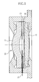
- Figure 1 is a sectional view of a photographic lens held in a lens holder;
- Figure 2 is a schematic diagram showing a lens structure according to Example 1 of the present invention;
- Figure 3 is a diagram showing transverse aberrations according to Example 1 of the present invention;
- Figure 4 is a schematic diagram showing longitudinal aberrations according to Example 1;
- Figure 5 is a schematic diagram showing a lens structure according to Example 2 of the present invention;
- Figure 6 is a diagram showing transverse aberrations according to Example 2 of the present invention;
- Figure 7 is a schematic diagram showing longitudinal aberrations according to Example 2;
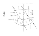
- Figure 8 is a schematic diagram showing a lens structure according to Example 3 of the present invention;
- Figure 9 is a diagram showing transverse aberrations according to Example 3 of the present invention; and
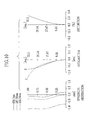
- Figure 10 is a schematic diagram showing longitudinal aberrations according to Example 3.
-
- In Fig.1, a
photographic lens 10 consists of, in the order from the object side, a firstpositive lens 11 and a secondpositive lens 12. - The first
positive lens 11 is a meniscus lens having a convex object side surface and a concave image side surface. - Both the image side surface of the first
positive lens 11 and an image side surface of the secondpositive lens 12 are formed to be aspherical. - The second
positive lens 12 is a double-convex lens having convex surfaces on both sides. - A
spacer 13 and an aperture stop (a first stop) 14 are disposed between the firstpositive lens 11 and the secondpositive lens 12. Thespacer 13 provides a space between the twolens elements aperture stop 14 limits the quantity of light from the subject that enters through thephotographic lens 10. - The
spacer 13 serves as a flare stop for blocking extraneous light beams that may fall in from outside the filed angle and cause flares. - The
aperture stop 14 is placed on the image side of thespacer 13, and defines an effective aperture size at which thephotographic lens 10 has the highest possible speed while obtaining satisfying image-forming performance - The
spacer 13 is formed to have a thinned portion on the object side so as to provide a gap between the firstpositive lens 11 and thespacer 13. Into this gap is inserted a movable stop member (a second stop) 15 with a smaller stop size than theaperture stop 14. Then themovable stop member 15 is set in a light path of the light that travels from the subject through thephotographic lens 10. - The
movable stop member 15 is switched over between the position inserted in the subject light path and a position retracted from the subject light path, for example, as being driven by a driver, such as a solenoid, that is connected to a photometry circuit measuring the subject brightness. Themovable stop member 15 may be manually switched over. - While the
movable stop member 15 is inserted in the subject light path, over-exposure is prevented at the photography under bright day light or the like when the subject brightness is high. - At a low subject brightness, like at the night photography, the
movable stop member 15 is to be displaced from the light path so as to prevent under-exposure. - The
movable stop member 15 placed on the object side of theaperture stop 14 restricts color dispersion of the subject light after passing through the firstpositive lens 11. Such color dispersion is due to chromatic aberration of magnification of the firstpositive lens 11. Therefore, this configuration prevents lowering the image quality of the photographs that can be caused by the chromatic aberration of magnification. - Now concrete examples of the present invention will be described.
- Fig.2 shows a lens structure of Example 1, and Tables 1 and 2 show lens data and aspherical coefficients for Example 1 respectively.
- Designated by "n" (n = 1, 2, 3 ...) is the surface number of respective lens surfaces in the order from the object side, "Rn" (n = 1, 2, 3 ...) is the radius of curvature of the respective lens surfaces, "Dn" is the thickness of the lenses or the air space between the lenses, "Nd" and "vd" are the refractive index and the dispersive power with respect to d-line (587.56 nm).
- The same applies to the other examples.
- The second and fourth surfaces, i.e. the image side surfaces of the first and second lenses, are aspherical in any example, and these aspherical surfaces satisfy the following condition:
- In the above equation, "c" is a reciprocal to the radius of curvature (c = 1/Rn) and "h" is a height from the optical axis.
n Rn Dn Nd νd 1 5.042 2.1 1.492 57.5 2 5.07* 1.87 Stop Infinity 0.1 3 66.41 1.42 1.492 57.5 4 -35.664* 26.34 Film -149.33 -0.595 n 2 4 K 0.056484 0.000000 A 0.3799777E-3 -0.286163E-3 B 0.537644E-4 0.362122E-4 C -0.79496E-6 -0.319652E-5 D 0.000000 0.52393E-7 - By setting the numerical values as above, the total focal length F of the
photographic lens 10, the focal length F1 of thefirst lens 11, the focal length F2 of thesecond lens 12, the f-number f (the ratio of the total focal length F to the effective aperture size of the aperture stop 14), and the half view angle ω of thephotographic lens 10 will have the following values: F = 31.9 mm;
F1 = 71.93 mm;
F2 = 47.37 mm;
f = 5.9; and
ω = 34.8° . - Therefore,
F/F1 = 0.44;
R1/f = 0.158; and
(F/R3)•f = 2.83
wherein R1 is the radius of curvature of the first surface, R3 is the radius of curvature of the third surface. - According to Example 1, the flange back varies by 0.066 mm as the center thickness of the
first lens element 11 varies by 0.01 mm. So the error sensitivity is 6.6 times. - Various aberrations of Example 1 are illustrated in Figs. 3 and 4.
- Fig.5 shows a lens structure of Example 2, and Tables 3 and 4 show lens data and aspherical coefficients for Example 2 respectively.
n Rn Dn Nd νd 1 5.699 2.65 1.492 57.5 2 5.775* 1.762 Stop Infinity 0.1 3 119.687 2.255 1.492 57.5 4 -28.524* 25.4 Film -149.33 -0.54 n 2 4 K 0.0529637 0.000000 A -0.160337E-4 -0.119867E-3 B 0.411345E-4 -0.271515E-6 C -0.226599E-5 0.132466E-6 D 0.000000 -0.305712E-7 - According to Example 2, the total focal length F of the
photographic lens 10, the focal length F1 of thefirst lens 11, the focal length F2 of thesecond lens 12, the f-number f (the ratio of the effective aperture size of theaperture stop 14 to the total focal length F), and the half view angle ω of thephotographic lens 10 will have the following values:
F = 32 mm;
F1 = 70.49 mm;
F2 = 47.05 mm;
f = 5.6 ; and
ω = 34.8° . - Therefore,
F/F1 - 0.45;
R1/f = 0.178; and
(F/R3) · f = 1.5. - According to Example 2, the flange back varies by 0.052 mm as the center thickness of the first lens element 2 varies by 0.01 mm. So the error sensitivity is 5.2 times.
- Various aberrations of Example 2 are illustrated in Figs. 6 and 7.
- Fig.8 shows a lens structure of Example 3, and Tables 5 and 6 show lens data and aspherical coefficients for Example 3 respectively.
n Rn Dn Nd νd 1 5.713 2.64 1.492 57.5 2 5.799* 1.76 Stop Infinity 0.1 3 127.53 2.25 1.492 57.5 4 -28.32* 25.41 Film -149.33 -0.59 n 2 4 K 1.2309 0.000000 A -0.501166E-3 -0.157315E-3 B 0.327578E-4 0.102189E-4 C -0.611505E-5 -0.879306E-6 D 0.000000 0.211327E-8 - According to Example 3, the total focal length F of the
photographic lens 10, the focal length F1 of thefirst lens 11, the focal length F2 of thesecond lens 12, the f-number f, and the half view angle ω will have the following values:
F = 32 mm;
F1 = 67 mm;
F2 = 47.32 mm;
f = 5.6; and
ω = 34.8° . - Therefore,
F/F1 = 0.48;
R1/f = 0.179; and
(F/R3) · f = 1.41. - According to Example 3, the flange back varies by 0.052 mm as the center thickness of the first lens element 2 varies by 0.01 mm. So the error sensitivity is 5.2 times.
- Various aberrations of Example 3 are illustrated in Figs. 9 and 10.
- As described so far, the photographic lens of the present invention reduces variations in flange back caused by variations in center thickness of the object side first lens element as compared to the conventional ones. In addition to that, the photographic lens of the present invention achieves a higher lens speed than conventional ones where the lens speed could not be higher than 6.4 in terms of f-number to maintain satisfactory image-forming performance.
- Because of the lower sensitivity to the dimensional error of the lens element, the photographic lens of the present invention is advantageous in manufacturability. Therefore the photographic lens of the present invention can improve the quality of photographs without requiring high accuracy in manufacture and thus without raising the manufacturing cost.
Claims (3)
- A photographic lens (10) comprising a first lens element (11), a second lens element (12) disposed on image side of said first lens element (11), and a first stop (14) disposed between said first and second lens elements (11, 12), said first lens element (11) being a meniscus lens having a convex object side surface, said second lens element (12) being a double-convex lens, said photographic lens (10) satisfying the following conditions:
5.6 ≤ f < 8;
F1 > F2;
0.39 < F/F1 ≤ 0.5;
0.15 < R1/F < 0.19;
1.4 < (F/R3) · f s 3.0; and
R3 > |R4|
wherein F is an overall focal length of the photographic lens (10), F1 is a focal length of said first lens element (11), F2 is a focal length of said second lens element (12), f is a ratio of the overall focal length F to an effective aperture size that is defined by the first stop (14), R1 is a radius of curvature of the object side surface of said first lens element (11), and R3 and R4 are radii of curvature of the object side spherical surface and of an average spherical surface of the image side aspherical surface of the second lens element (12) respectively. - A photographic lens as claimed in claim 1, wherein said first lens element (11) has an aspherical image side surface.
- A photographic lens as claimed in claim 1 or 2, further comprising a second stop (15) having a smaller aperture size, said second stop (15) being movable into and out of a light path between said first lens element (11) and said first stop (14).
Applications Claiming Priority (2)
| Application Number | Priority Date | Filing Date | Title |
|---|---|---|---|
| JP2003208052 | 2003-08-20 | ||
| JP2003208052A JP2005062282A (en) | 2003-08-20 | 2003-08-20 | Photographic lens |
Publications (2)
| Publication Number | Publication Date |
|---|---|
| EP1508828A1 true EP1508828A1 (en) | 2005-02-23 |
| EP1508828B1 EP1508828B1 (en) | 2006-05-31 |
Family
ID=34055953
Family Applications (1)
| Application Number | Title | Priority Date | Filing Date |
|---|---|---|---|
| EP04254728A Expired - Lifetime EP1508828B1 (en) | 2003-08-20 | 2004-08-05 | Photographic lens |
Country Status (4)
| Country | Link |
|---|---|
| US (1) | US7031080B2 (en) |
| EP (1) | EP1508828B1 (en) |
| JP (1) | JP2005062282A (en) |
| DE (1) | DE602004001027T2 (en) |
Cited By (1)
| Publication number | Priority date | Publication date | Assignee | Title |
|---|---|---|---|---|
| CN102236154A (en) * | 2010-05-05 | 2011-11-09 | 大立光电股份有限公司 | Thinned imaging lens group |
Families Citing this family (7)
| Publication number | Priority date | Publication date | Assignee | Title |
|---|---|---|---|---|
| US8016417B2 (en) * | 2008-07-02 | 2011-09-13 | Abraham Reichert | Eye model |
| TWI479221B (en) * | 2010-12-16 | 2015-04-01 | Hon Hai Prec Ind Co Ltd | Prime lens |
| US8848299B2 (en) | 2011-01-24 | 2014-09-30 | AO Ether Corporation | Two lens module including a plano-convex lens |
| KR20150092458A (en) * | 2014-02-05 | 2015-08-13 | 삼성전기주식회사 | Lens Module |
| CN113009675B (en) * | 2021-03-24 | 2022-05-13 | 天津欧菲光电有限公司 | Optical system, image capturing module and electronic equipment |
| CN113504631B (en) * | 2021-07-22 | 2023-06-23 | 广东旭业光电科技股份有限公司 | Lens assembly and light and thin type camera lens |
| TWI782827B (en) * | 2021-12-17 | 2022-11-01 | 揚明光學股份有限公司 | Projection lens for vehicle and projector for vehicle |
Citations (6)
| Publication number | Priority date | Publication date | Assignee | Title |
|---|---|---|---|---|
| US5327291A (en) * | 1992-03-30 | 1994-07-05 | Polaroid Corporation | Compact objective lens |
| US5604639A (en) * | 1994-12-30 | 1997-02-18 | Eastman Kodak Company | Two-element optical system and camera and method of making a camera |
| JPH1090597A (en) * | 1996-09-17 | 1998-04-10 | Kiyousera Opt Kk | Shooting lens |
| US5978159A (en) * | 1996-12-02 | 1999-11-02 | Olympus Optical Co., Ltd. | Hybrid photographic objective |
| JP2000227626A (en) * | 1999-02-05 | 2000-08-15 | Konica Corp | Film unit with lens |
| JP2002296496A (en) * | 2001-03-29 | 2002-10-09 | Fuji Photo Optical Co Ltd | Monofocal lens |
Family Cites Families (4)
| Publication number | Priority date | Publication date | Assignee | Title |
|---|---|---|---|---|
| JP2848523B2 (en) * | 1996-09-27 | 1999-01-20 | 株式会社日出 | Imaging lens |
| DE69728183T2 (en) * | 1996-11-29 | 2005-03-17 | 3M Innovative Properties Co., St. Paul | LENSES FOR ELECTRONIC PICTURE SYSTEMS |
| JP2000227547A (en) * | 1999-02-05 | 2000-08-15 | Fuji Photo Film Co Ltd | Photographic lens and camera using the same |
| JP2002023050A (en) | 2000-07-06 | 2002-01-23 | Fuji Photo Film Co Ltd | Photographing lens |
-
2003
- 2003-08-20 JP JP2003208052A patent/JP2005062282A/en not_active Withdrawn
-
2004
- 2004-08-05 DE DE602004001027T patent/DE602004001027T2/en not_active Expired - Fee Related
- 2004-08-05 EP EP04254728A patent/EP1508828B1/en not_active Expired - Lifetime
- 2004-08-20 US US10/921,919 patent/US7031080B2/en not_active Expired - Fee Related
Patent Citations (6)
| Publication number | Priority date | Publication date | Assignee | Title |
|---|---|---|---|---|
| US5327291A (en) * | 1992-03-30 | 1994-07-05 | Polaroid Corporation | Compact objective lens |
| US5604639A (en) * | 1994-12-30 | 1997-02-18 | Eastman Kodak Company | Two-element optical system and camera and method of making a camera |
| JPH1090597A (en) * | 1996-09-17 | 1998-04-10 | Kiyousera Opt Kk | Shooting lens |
| US5978159A (en) * | 1996-12-02 | 1999-11-02 | Olympus Optical Co., Ltd. | Hybrid photographic objective |
| JP2000227626A (en) * | 1999-02-05 | 2000-08-15 | Konica Corp | Film unit with lens |
| JP2002296496A (en) * | 2001-03-29 | 2002-10-09 | Fuji Photo Optical Co Ltd | Monofocal lens |
Non-Patent Citations (3)
| Title |
|---|
| PATENT ABSTRACTS OF JAPAN vol. 1998, no. 09 31 July 1998 (1998-07-31) * |
| PATENT ABSTRACTS OF JAPAN vol. 2000, no. 11 3 January 2001 (2001-01-03) * |
| PATENT ABSTRACTS OF JAPAN vol. 2003, no. 02 5 February 2003 (2003-02-05) * |
Cited By (2)
| Publication number | Priority date | Publication date | Assignee | Title |
|---|---|---|---|---|
| CN102236154A (en) * | 2010-05-05 | 2011-11-09 | 大立光电股份有限公司 | Thinned imaging lens group |
| CN102236154B (en) * | 2010-05-05 | 2013-03-13 | 大立光电股份有限公司 | Thinned imaging lens group |
Also Published As
| Publication number | Publication date |
|---|---|
| US20050041309A1 (en) | 2005-02-24 |
| US7031080B2 (en) | 2006-04-18 |
| DE602004001027D1 (en) | 2006-07-06 |
| DE602004001027T2 (en) | 2006-11-09 |
| EP1508828B1 (en) | 2006-05-31 |
| JP2005062282A (en) | 2005-03-10 |
Similar Documents
| Publication | Publication Date | Title |
|---|---|---|
| US9618731B2 (en) | Optical system and image pickup apparatus including the same | |
| US6335835B1 (en) | Taking lens for fixed-focus photographic camera | |
| US10073252B2 (en) | Optical system and image pickup apparatus including the same | |
| US8018663B2 (en) | Image forming lens, camera and portable information terminal | |
| US7593163B2 (en) | Rear converter lens apparatus and taking system comprising the same | |
| US8934182B2 (en) | Lens system and optical apparatus | |
| US7173776B2 (en) | Fisheye lens system | |
| US6891684B2 (en) | Image taking lens system | |
| US20100208367A1 (en) | Photographic lens and image pickup apparatus having the same | |
| US6600609B2 (en) | Inner-focus-type lens | |
| KR20030017395A (en) | Lens system and camera having the same | |
| US6844987B2 (en) | Zoom lens system for covering superwide-angle area | |
| US6747817B2 (en) | Macro lens, and camera comprising the same | |
| US7855837B2 (en) | Viewing optical system and imaging apparatus incorporating the same | |
| EP1508828B1 (en) | Photographic lens | |
| US8014074B2 (en) | Finder optical system and image pickup apparatus using the same | |
| US20020196564A1 (en) | Wide-angle, single focus lens | |
| US12326542B2 (en) | Lens optical system | |
| JP3588517B2 (en) | Imaging lens | |
| US5392082A (en) | Photographing apparatus having a trimming photographic mode | |
| US20070097521A1 (en) | Zoom lens optical system | |
| JPH0868935A (en) | Camera provided with triplet lens | |
| US20100177407A1 (en) | Lens system | |
| JP2000266997A (en) | Photographing lens and camera using same | |
| US20050259157A1 (en) | Optical system |
Legal Events
| Date | Code | Title | Description |
|---|---|---|---|
| PUAI | Public reference made under article 153(3) epc to a published international application that has entered the european phase |
Free format text: ORIGINAL CODE: 0009012 |
|
| AK | Designated contracting states |
Kind code of ref document: A1 Designated state(s): AT BE BG CH CY CZ DE DK EE ES FI FR GB GR HU IE IT LI LU MC NL PL PT RO SE SI SK TR |
|
| AX | Request for extension of the european patent |
Extension state: AL HR LT LV MK |
|
| 17P | Request for examination filed |
Effective date: 20050525 |
|
| GRAP | Despatch of communication of intention to grant a patent |
Free format text: ORIGINAL CODE: EPIDOSNIGR1 |
|
| AKX | Designation fees paid |
Designated state(s): DE FR GB |
|
| GRAS | Grant fee paid |
Free format text: ORIGINAL CODE: EPIDOSNIGR3 |
|
| GRAA | (expected) grant |
Free format text: ORIGINAL CODE: 0009210 |
|
| AK | Designated contracting states |
Kind code of ref document: B1 Designated state(s): DE FR GB |
|
| REG | Reference to a national code |
Ref country code: GB Ref legal event code: FG4D |
|
| REF | Corresponds to: |
Ref document number: 602004001027 Country of ref document: DE Date of ref document: 20060706 Kind code of ref document: P |
|
| ET | Fr: translation filed | ||
| RAP2 | Party data changed (patent owner data changed or rights of a patent transferred) |
Owner name: FUJIFILM CORPORATION |
|
| PLBE | No opposition filed within time limit |
Free format text: ORIGINAL CODE: 0009261 |
|
| STAA | Information on the status of an ep patent application or granted ep patent |
Free format text: STATUS: NO OPPOSITION FILED WITHIN TIME LIMIT |
|
| 26N | No opposition filed |
Effective date: 20070301 |
|
| REG | Reference to a national code |
Ref country code: FR Ref legal event code: TP Ref country code: FR Ref legal event code: CD |
|
| PGFP | Annual fee paid to national office [announced via postgrant information from national office to epo] |
Ref country code: DE Payment date: 20080821 Year of fee payment: 5 |
|
| PGFP | Annual fee paid to national office [announced via postgrant information from national office to epo] |
Ref country code: FR Payment date: 20080818 Year of fee payment: 5 |
|
| PGFP | Annual fee paid to national office [announced via postgrant information from national office to epo] |
Ref country code: GB Payment date: 20080813 Year of fee payment: 5 |
|
| GBPC | Gb: european patent ceased through non-payment of renewal fee |
Effective date: 20090805 |
|
| REG | Reference to a national code |
Ref country code: FR Ref legal event code: ST Effective date: 20100430 |
|
| PG25 | Lapsed in a contracting state [announced via postgrant information from national office to epo] |
Ref country code: FR Free format text: LAPSE BECAUSE OF NON-PAYMENT OF DUE FEES Effective date: 20090831 Ref country code: DE Free format text: LAPSE BECAUSE OF NON-PAYMENT OF DUE FEES Effective date: 20100302 |
|
| PG25 | Lapsed in a contracting state [announced via postgrant information from national office to epo] |
Ref country code: GB Free format text: LAPSE BECAUSE OF NON-PAYMENT OF DUE FEES Effective date: 20090805 |