EP1508814A2 - Accessory-type GPS receiver - Google Patents
Accessory-type GPS receiver Download PDFInfo
- Publication number
- EP1508814A2 EP1508814A2 EP04016858A EP04016858A EP1508814A2 EP 1508814 A2 EP1508814 A2 EP 1508814A2 EP 04016858 A EP04016858 A EP 04016858A EP 04016858 A EP04016858 A EP 04016858A EP 1508814 A2 EP1508814 A2 EP 1508814A2
- Authority
- EP
- European Patent Office
- Prior art keywords
- gps
- mobile terminal
- connector
- receiver
- type
- Prior art date
- Legal status (The legal status is an assumption and is not a legal conclusion. Google has not performed a legal analysis and makes no representation as to the accuracy of the status listed.)
- Ceased
Links
- 235000019504 cigarettes Nutrition 0.000 description 3
- 230000004075 alteration Effects 0.000 description 2
- 230000005540 biological transmission Effects 0.000 description 1
- 230000001413 cellular effect Effects 0.000 description 1
- 230000008878 coupling Effects 0.000 description 1
- 238000010168 coupling process Methods 0.000 description 1
- 238000005859 coupling reaction Methods 0.000 description 1
- 238000012986 modification Methods 0.000 description 1
- 230000004048 modification Effects 0.000 description 1
Images



Classifications
-
- G—PHYSICS
- G01—MEASURING; TESTING
- G01S—RADIO DIRECTION-FINDING; RADIO NAVIGATION; DETERMINING DISTANCE OR VELOCITY BY USE OF RADIO WAVES; LOCATING OR PRESENCE-DETECTING BY USE OF THE REFLECTION OR RERADIATION OF RADIO WAVES; ANALOGOUS ARRANGEMENTS USING OTHER WAVES
- G01S19/00—Satellite radio beacon positioning systems; Determining position, velocity or attitude using signals transmitted by such systems
- G01S19/01—Satellite radio beacon positioning systems transmitting time-stamped messages, e.g. GPS [Global Positioning System], GLONASS [Global Orbiting Navigation Satellite System] or GALILEO
- G01S19/13—Receivers
- G01S19/35—Constructional details or hardware or software details of the signal processing chain
- G01S19/36—Constructional details or hardware or software details of the signal processing chain relating to the receiver frond end
-
- H—ELECTRICITY
- H04—ELECTRIC COMMUNICATION TECHNIQUE
- H04B—TRANSMISSION
- H04B1/00—Details of transmission systems, not covered by a single one of groups H04B3/00 - H04B13/00; Details of transmission systems not characterised by the medium used for transmission
- H04B1/38—Transceivers, i.e. devices in which transmitter and receiver form a structural unit and in which at least one part is used for functions of transmitting and receiving
- H04B1/40—Circuits
-
- G—PHYSICS
- G01—MEASURING; TESTING
- G01S—RADIO DIRECTION-FINDING; RADIO NAVIGATION; DETERMINING DISTANCE OR VELOCITY BY USE OF RADIO WAVES; LOCATING OR PRESENCE-DETECTING BY USE OF THE REFLECTION OR RERADIATION OF RADIO WAVES; ANALOGOUS ARRANGEMENTS USING OTHER WAVES
- G01S19/00—Satellite radio beacon positioning systems; Determining position, velocity or attitude using signals transmitted by such systems
- G01S19/01—Satellite radio beacon positioning systems transmitting time-stamped messages, e.g. GPS [Global Positioning System], GLONASS [Global Orbiting Navigation Satellite System] or GALILEO
- G01S19/13—Receivers
- G01S19/35—Constructional details or hardware or software details of the signal processing chain
-
- H—ELECTRICITY
- H01—ELECTRIC ELEMENTS
- H01Q—ANTENNAS, i.e. RADIO AERIALS
- H01Q1/00—Details of, or arrangements associated with, antennas
- H01Q1/12—Supports; Mounting means
- H01Q1/22—Supports; Mounting means by structural association with other equipment or articles
- H01Q1/24—Supports; Mounting means by structural association with other equipment or articles with receiving set
-
- H—ELECTRICITY
- H04—ELECTRIC COMMUNICATION TECHNIQUE
- H04B—TRANSMISSION
- H04B1/00—Details of transmission systems, not covered by a single one of groups H04B3/00 - H04B13/00; Details of transmission systems not characterised by the medium used for transmission
- H04B1/38—Transceivers, i.e. devices in which transmitter and receiver form a structural unit and in which at least one part is used for functions of transmitting and receiving
- H04B1/3805—Transceivers, i.e. devices in which transmitter and receiver form a structural unit and in which at least one part is used for functions of transmitting and receiving with built-in auxiliary receivers
-
- H—ELECTRICITY
- H04—ELECTRIC COMMUNICATION TECHNIQUE
- H04M—TELEPHONIC COMMUNICATION
- H04M1/00—Substation equipment, e.g. for use by subscribers
- H04M1/60—Substation equipment, e.g. for use by subscribers including speech amplifiers
- H04M1/6033—Substation equipment, e.g. for use by subscribers including speech amplifiers for providing handsfree use or a loudspeaker mode in telephone sets
- H04M1/6041—Portable telephones adapted for handsfree use
- H04M1/6075—Portable telephones adapted for handsfree use adapted for handsfree use in a vehicle
-
- H—ELECTRICITY
- H04—ELECTRIC COMMUNICATION TECHNIQUE
- H04M—TELEPHONIC COMMUNICATION
- H04M1/00—Substation equipment, e.g. for use by subscribers
- H04M1/72—Mobile telephones; Cordless telephones, i.e. devices for establishing wireless links to base stations without route selection
- H04M1/724—User interfaces specially adapted for cordless or mobile telephones
- H04M1/72403—User interfaces specially adapted for cordless or mobile telephones with means for local support of applications that increase the functionality
- H04M1/72409—User interfaces specially adapted for cordless or mobile telephones with means for local support of applications that increase the functionality by interfacing with external accessories
-
- G—PHYSICS
- G01—MEASURING; TESTING
- G01S—RADIO DIRECTION-FINDING; RADIO NAVIGATION; DETERMINING DISTANCE OR VELOCITY BY USE OF RADIO WAVES; LOCATING OR PRESENCE-DETECTING BY USE OF THE REFLECTION OR RERADIATION OF RADIO WAVES; ANALOGOUS ARRANGEMENTS USING OTHER WAVES
- G01S19/00—Satellite radio beacon positioning systems; Determining position, velocity or attitude using signals transmitted by such systems
- G01S19/01—Satellite radio beacon positioning systems transmitting time-stamped messages, e.g. GPS [Global Positioning System], GLONASS [Global Orbiting Navigation Satellite System] or GALILEO
- G01S19/13—Receivers
- G01S19/34—Power consumption
-
- H—ELECTRICITY
- H04—ELECTRIC COMMUNICATION TECHNIQUE
- H04M—TELEPHONIC COMMUNICATION
- H04M1/00—Substation equipment, e.g. for use by subscribers
- H04M1/72—Mobile telephones; Cordless telephones, i.e. devices for establishing wireless links to base stations without route selection
- H04M1/724—User interfaces specially adapted for cordless or mobile telephones
- H04M1/72403—User interfaces specially adapted for cordless or mobile telephones with means for local support of applications that increase the functionality
- H04M1/72409—User interfaces specially adapted for cordless or mobile telephones with means for local support of applications that increase the functionality by interfacing with external accessories
- H04M1/724098—Interfacing with an on-board device of a vehicle
-
- H—ELECTRICITY
- H04—ELECTRIC COMMUNICATION TECHNIQUE
- H04M—TELEPHONIC COMMUNICATION
- H04M2250/00—Details of telephonic subscriber devices
- H04M2250/10—Details of telephonic subscriber devices including a GPS signal receiver
Definitions
- the present invention relates generally to GPS receiving devices and more particularly to a mobile accessory-type GPS receiver.
- the GPS Global Positioning System
- the GPS comprises 24 satellites orbiting 12,000 miles above the Earth, each one making two complete rotations per day.
- the orbits are arranged so that at any time, anywhere on Earth, there are at least four satellites "visible” in the sky.
- GPS receivers are designed to locate four or more of these satellites, figure out the relative distance to each satellite, and use this information to deduce its own location.
- GPS makes it possible for users equipped with ground receivers to pinpoint their own geographic location with ever-increasing accuracy.
- location accuracy may be anywhere from 10 to 100 meters for most run-of the-mill GPS equipment.
- Accuracy may be pinpointed to within one (1) meter with military-approved equipment.
- Mobile GPS receivers have presently become sufficiently low-cost and portable to attract a relatively large pool of users thus becoming common consumer products.
- mobile GPS receivers are being used in vehicles to correlate the driver's location with traffic and weather information.
- Mobile GPS receivers are generally of the cradle or accessory type.
- Fig. 1 generally illustrates a cradle-type GPS receiver 10 which may be used in vehicles. With this type of receiver, a GPS antenna may be affixed at an arbitrary position inside the vehicle so as to implement an optimal GPS reception environment.
- Fig. 2 generally depicts an accessory-type GPS receiver 12 which may be carried around by an individual user. With this type of receiver, an active GPS antenna (not shown) is integrally coupled to the GPS receiver 12.
- the accessory-type GPS receiver 12 may be operatively coupled to a mobile terminal 14 via a data link cable 16.
- the accessory-type GPS receiver 12 may also be portable enough to be worn like a necklace or stored in a shirt pocket or the like.
- the cradle-type GPS receiver 10 cannot be carried around like an accessory-type GPS receiver. If the user desires to adapt the GPS receiver 10 for additional functionality, a new special cradle would have to be used which would add to the cost of usage.
- the accessory-type GPS receiver 12 also carries some inherent disadvantages.
- the data link cable 16 may not be used to power the accessory-type GPS receiver 12 and charge the battery of the mobile terminal 14 at the same time.
- wearing the accessory-type GPS receiver 12 around one's neck or in one's shirt pocket while hand-carrying the mobile terminal 14, which is coupled to the accessory-type GPS receiver 12 may be somewhat cumbersome for some mobile GPS receiver users.
- an accessory-type GPS receiver comprises at least one mobile terminal side plug connector, at least one cradle/hand-free side receptacle connector, and at least one power supply receiving power from at least one mobile terminal power charge line being operatively coupled between the mobile terminal side plug connector and the cradle/hand-free side receptacle connector.
- the mobile terminal side plug connector may be disposed substantially opposite the cradle/hand-free side receptacle connector.
- the accessory-type GPS receiver further comprises at least one GPS signal processor adapted for UART (Universal Asynchronous Receiver/Transmitter) communication with at least one mobile terminal via the mobile terminal side plug connector.
- the GPS signal processor receives power from the power supply.
- the GPS signal processor also receives power from at least one coin power cell to maintain backed-up GPS data while the GPS signal processor is in a state of "sleep".
- the accessory-type GPS receiver further comprises at least one switch-type antenna portion being operatively coupled to the GPS signal processor via at least one GPS RF (Radio Frequency) filter, the switch-type antenna portion being used for wireless communication with at least one GPS satellite.
- the switch-type antenna portion comprises at least one internal passive GPS antenna, and at least one external active GPS antenna. When the internal passive GPS antenna is in an "on” state, the external active GPS antenna is in an “off” state, and vice versa.
- Each of the mobile terminal side plug connector and the cradle/hand-free side receptacle connector may be a standard 24-pin connector, respectively.
- an accessory-type GPS receiver comprises at least one plug-type connector used to pass GPS data directly to at least one mobile terminal, at least one receptacle-type connector used to pass non-GPS data to the mobile terminal via the plug-type connector, and at least one power supply receiving power from at least one mobile terminal power charge line being operatively coupled between the plug-type connector and the receptacle-type connector.
- the plug-type connector may be disposed substantially opposite the receptacle-type connector.
- the accessory-type GPS receiver further comprises at least one GPS signal processor adapted for UART communication with the mobile terminal via the plug-type connector.
- the GPS signal processor receives power from the power supply.
- the GPS signal processor also receives power from at least one coin power cell to maintain backed-up GPS data while the GPS signal processor is in a state of "sleep".
- the accessory-type GPS receiver further comprises at least one switch-type antenna portion being operatively coupled to the GPS signal processor via at least one GPS RF filter, the switch-type antenna portion being used for wireless communication with at least one GPS satellite.
- the switch-type antenna portion comprises at least one internal passive GPS antenna, and at least one external active GPS antenna. When the internal passive GPS antenna is in an "on” state, the external active GPS antenna is in an “off” state, and vice versa.
- Each of the plug-type connector and the receptacle-type connector may be a standard 24-pin connector, respectively.
- an accessory-type GPS receiver 18 preferably includes an integral mobile terminal side plug connection portion 20 and an integral cradle/hand-free side receptacle connection portion 22 disposed substantially opposite mobile terminal plug connection portion 20.
- accessory-type GPS receiver 18 may be configured as a portable unit approximately the size of a matchbox.
- Other GPS receiver configurations may be used, provided such other configurations do not depart from the intended purpose of the present invention.
- the accessory-type GPS receiver 18 may be directly coupled to a mobile terminal 24 via side plug connection portion 20 (i.e. without using cable(s)), and to another device, such as a vehicle cigarette jack mobile terminal charger 26, via side receptacle connection portion 22.
- Mobile terminal 24 may be a cellular telephone, as generally shown in Fig. 3B, a PDA (Personal Digital Assistant), a tablet PC (Personal Computer), a laptop computer, or the like.
- the accessory-type GPS receiver 18 may be operatively coupled to other devices, such as a UART (Universal Asynchronous Receiver/Transmitter) type data link cable, a USB (Universal Serial Bus) type data link cable, an external USB mobile terminal hard drive and the like, via side receptacle connection portion 22, as needed, provided such couplings do not depart from the spirit and scope of the present invention.
- UART Universal Asynchronous Receiver/Transmitter
- USB Universal Serial Bus
- the accessory-type GPS receiver 18 comprises a switch-type antenna portion 28 being operatively coupled to a GPS signal processor 34 via a GPS RF (Radio Frequency) filter 36.
- Switch-type antenna portion 28 includes an internal chip-type passive GPS antenna 30 and an external active GPS antenna 32. Switch-type antenna portion 28 receives/transmits wireless GPS signals from/to GPS satellites.
- external GPS antenna 32 When external GPS antenna 32 is operatively connected, internal GPS antenna 30 is in an "off" state, i.e. not functioning. Similarly, when internal GPS antenna 30 is operatively connected, external GPS antenna 32 is in an "off" state, as generally shown in Fig. 4. Antenna switching is being done automatically according to GPS reception needs in real time.
- GPS signal processor 34 receives wireless GPS signals from switch-type antenna portion 28 (via GPS RF filter 36) and outputs corresponding position information to a mobile terminal, such as mobile terminal 24 in Fig. 3B, according to a pre-designated data transmission protocol via a UART connection and integral mobile terminal side plug connection portion 20, as generally illustrated in Fig. 4.
- GPS signal processor 34 receives power from an integral power supply 38 and a coin power cell 40.
- Coin power cell 40 is used to provide power for backed-up GPS data when GPS signal processor 34 is in a state of "sleep", i.e. being powered off.
- GPS signal processor 34 is in an operative state when being powered by power supply 38.
- GPS signal processor 34 may be powered on/off via mobile terminal key input or via an integral power switch. GPS signal processor 34 may also be powered on/off via a mobile terminal power charge line 42 operatively coupled between mobile terminal side plug connection portion 20, cradle/hand-free side receptacle connection portion 22, and power supply 38, as generally illustrated in Fig. 4. Specifically, power charge line 42 feeds power into power supply 38 and mobile terminal 24 via side plug connection portion 20.
- This type of power sharing functionality allows GPS receiver 18 to operate continuously while the battery of mobile terminal 24 is being re-charged, provided GPS receiver 18 is operatively connected between vehicle cigarette jack mobile terminal charger 26 and mobile terminal 24, as generally depicted in Fig. 3.
- receptacle connection portion 22 may be used to pass various non-GPS related signals to/from mobile terminal 24 via plug connection portion 20, i.e. bypassing the GPS circuitry of GPS receiver 18.
- non-GPS related signals may include, for example, audio in/out signals, PCM (Pulse Code Modulation) clk/sync signals, USB, external power signals, etc.
- side plug connection portion 20 may be configured as a standard 24-pin connector (Fig. 5) adapted to mate with a corresponding data link connector on mobile terminal 24 (Fig. 3).
- the 4th and 5th pins of 24-pin connector 20 may be designated for input of external power, while the 21st and 22nd pins may be designated for input from a 4.2 V battery charge power.
- Other pins may be used to pass UART position information to mobile terminal 24.
- side receptacle connection portion 22 may be configured as a standard 24-pin connector (Fig. 6) adapted to mate with a corresponding connector on vehicle cigarette jack mobile terminal charger 26 (Fig. 3).
- the 7th, 8th, 9th and 11th pins of 24-pin connector 22 may be used to pass through PCM data signals to mobile terminal 24 via side plug connection portion 20.
Landscapes
- Engineering & Computer Science (AREA)
- Signal Processing (AREA)
- Computer Networks & Wireless Communication (AREA)
- Remote Sensing (AREA)
- Radar, Positioning & Navigation (AREA)
- Physics & Mathematics (AREA)
- General Physics & Mathematics (AREA)
- Human Computer Interaction (AREA)
- Position Fixing By Use Of Radio Waves (AREA)
- Navigation (AREA)
- Telephone Set Structure (AREA)
- Mobile Radio Communication Systems (AREA)
- Telephone Function (AREA)
Abstract
Description
- The present invention relates generally to GPS receiving devices and more particularly to a mobile accessory-type GPS receiver.
- The GPS (Global Positioning System) comprises 24 satellites orbiting 12,000 miles above the Earth, each one making two complete rotations per day. The orbits are arranged so that at any time, anywhere on Earth, there are at least four satellites "visible" in the sky. GPS receivers are designed to locate four or more of these satellites, figure out the relative distance to each satellite, and use this information to deduce its own location.
- GPS makes it possible for users equipped with ground receivers to pinpoint their own geographic location with ever-increasing accuracy. In general, the location accuracy may be anywhere from 10 to 100 meters for most run-of the-mill GPS equipment. Accuracy may be pinpointed to within one (1) meter with military-approved equipment.
- Mobile GPS receivers have presently become sufficiently low-cost and portable to attract a relatively large pool of users thus becoming common consumer products. In addition to their outdoor use, such as during hiking, cross-country skiing, ballooning, flying, and sailing, mobile GPS receivers are being used in vehicles to correlate the driver's location with traffic and weather information.
- Mobile GPS receivers are generally of the cradle or accessory type. Fig. 1 generally illustrates a cradle-
type GPS receiver 10 which may be used in vehicles. With this type of receiver, a GPS antenna may be affixed at an arbitrary position inside the vehicle so as to implement an optimal GPS reception environment. - Fig. 2 generally depicts an accessory-
type GPS receiver 12 which may be carried around by an individual user. With this type of receiver, an active GPS antenna (not shown) is integrally coupled to theGPS receiver 12. The accessory-type GPS receiver 12 may be operatively coupled to amobile terminal 14 via adata link cable 16. The accessory-type GPS receiver 12 may also be portable enough to be worn like a necklace or stored in a shirt pocket or the like. - In contrast, the cradle-
type GPS receiver 10 cannot be carried around like an accessory-type GPS receiver. If the user desires to adapt theGPS receiver 10 for additional functionality, a new special cradle would have to be used which would add to the cost of usage. - The accessory-
type GPS receiver 12, however, also carries some inherent disadvantages. For example, thedata link cable 16 may not be used to power the accessory-type GPS receiver 12 and charge the battery of themobile terminal 14 at the same time. Also, wearing the accessory-type GPS receiver 12 around one's neck or in one's shirt pocket while hand-carrying themobile terminal 14, which is coupled to the accessory-type GPS receiver 12 may be somewhat cumbersome for some mobile GPS receiver users. - In accordance with one aspect of the present invention, an accessory-type GPS receiver comprises at least one mobile terminal side plug connector, at least one cradle/hand-free side receptacle connector, and at least one power supply receiving power from at least one mobile terminal power charge line being operatively coupled between the mobile terminal side plug connector and the cradle/hand-free side receptacle connector.
- The mobile terminal side plug connector may be disposed substantially opposite the cradle/hand-free side receptacle connector. The accessory-type GPS receiver further comprises at least one GPS signal processor adapted for UART (Universal Asynchronous Receiver/Transmitter) communication with at least one mobile terminal via the mobile terminal side plug connector. The GPS signal processor receives power from the power supply. The GPS signal processor also receives power from at least one coin power cell to maintain backed-up GPS data while the GPS signal processor is in a state of "sleep".
- The accessory-type GPS receiver further comprises at least one switch-type antenna portion being operatively coupled to the GPS signal processor via at least one GPS RF (Radio Frequency) filter, the switch-type antenna portion being used for wireless communication with at least one GPS satellite. The switch-type antenna portion comprises at least one internal passive GPS antenna, and at least one external active GPS antenna. When the internal passive GPS antenna is in an "on" state, the external active GPS antenna is in an "off" state, and vice versa.
- Each of the mobile terminal side plug connector and the cradle/hand-free side receptacle connector may be a standard 24-pin connector, respectively.
- In accordance with another aspect of the present invention, an accessory-type GPS receiver comprises at least one plug-type connector used to pass GPS data directly to at least one mobile terminal, at least one receptacle-type connector used to pass non-GPS data to the mobile terminal via the plug-type connector, and at least one power supply receiving power from at least one mobile terminal power charge line being operatively coupled between the plug-type connector and the receptacle-type connector.
- The plug-type connector may be disposed substantially opposite the receptacle-type connector. The accessory-type GPS receiver further comprises at least one GPS signal processor adapted for UART communication with the mobile terminal via the plug-type connector.
- The GPS signal processor receives power from the power supply. The GPS signal processor also receives power from at least one coin power cell to maintain backed-up GPS data while the GPS signal processor is in a state of "sleep".
- The accessory-type GPS receiver further comprises at least one switch-type antenna portion being operatively coupled to the GPS signal processor via at least one GPS RF filter, the switch-type antenna portion being used for wireless communication with at least one GPS satellite. The switch-type antenna portion comprises at least one internal passive GPS antenna, and at least one external active GPS antenna. When the internal passive GPS antenna is in an "on" state, the external active GPS antenna is in an "off" state, and vice versa.
- Each of the plug-type connector and the receptacle-type connector may be a standard 24-pin connector, respectively.
- These and other aspects of the present invention will become apparent from a review of the accompanying drawings and the following detailed description of the present invention.
- The present invention is generally shown by way of reference to the accompanying drawings as follows.
- Figure 1 schematically illustrates a conventional cradle-type GPS receiver.
- Figure 2 schematically illustrates a conventional accessory-type GPS receiver being operatively coupled to a mobile terminal.
- Figure 3A is a top plan view of an accessory-type GPS receiver in accordance with the present invention.
- Figure 3B schematically illustrates the accessory-type GPS receiver of Figure 3A being used in accordance with the present invention.
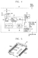
- Figure 4 schematically illustrates the architecture of an accessory-type GPS receiver in accordance with one embodiment of the present invention.
- Figure 5 is a top perspective view of a mobile terminal side plug-type connector of the accessory-type GPS receiver of Figure 3A in accordance with one embodiment of the present invention.
- Figure 6 is a top perspective view of a cradle/hand-free side receptacle-type connector of the accessory-type GPS receiver of Figure 3A in accordance with another embodiment of the present invention.
-
- Some embodiments of the present invention will be described in detail with reference to the related drawings of Figs. 1-6. Additional embodiments, features and/or advantages of the invention will become apparent from the ensuing description or may be learned by practicing the invention.
- In the figures, the drawings are not to scale with like numerals referring to like features throughout both the drawings and the description.
- The following description includes the best mode presently contemplated for carrying out the invention. This description is not to be taken in a limiting sense, but is made merely for the purpose of describing the general principles of the invention.
- As shown in Fig. 3A, an accessory-
type GPS receiver 18 preferably includes an integral mobile terminal sideplug connection portion 20 and an integral cradle/hand-free sidereceptacle connection portion 22 disposed substantially opposite mobile terminalplug connection portion 20. In one embodiment, accessory-type GPS receiver 18 may be configured as a portable unit approximately the size of a matchbox. Other GPS receiver configurations may be used, provided such other configurations do not depart from the intended purpose of the present invention. - As shown in Fig. 3B, the accessory-
type GPS receiver 18 may be directly coupled to amobile terminal 24 via side plug connection portion 20 (i.e. without using cable(s)), and to another device, such as a vehicle cigarette jack mobileterminal charger 26, via sidereceptacle connection portion 22.Mobile terminal 24 may be a cellular telephone, as generally shown in Fig. 3B, a PDA (Personal Digital Assistant), a tablet PC (Personal Computer), a laptop computer, or the like. - The accessory-
type GPS receiver 18 may be operatively coupled to other devices, such as a UART (Universal Asynchronous Receiver/Transmitter) type data link cable, a USB (Universal Serial Bus) type data link cable, an external USB mobile terminal hard drive and the like, via sidereceptacle connection portion 22, as needed, provided such couplings do not depart from the spirit and scope of the present invention. - As shown in Fig. 4, the accessory-
type GPS receiver 18 comprises a switch-type antenna portion 28 being operatively coupled to aGPS signal processor 34 via a GPS RF (Radio Frequency)filter 36. Switch-type antenna portion 28 includes an internal chip-typepassive GPS antenna 30 and an external active GPS antenna 32. Switch-type antenna portion 28 receives/transmits wireless GPS signals from/to GPS satellites. When external GPS antenna 32 is operatively connected,internal GPS antenna 30 is in an "off" state, i.e. not functioning. Similarly, wheninternal GPS antenna 30 is operatively connected, external GPS antenna 32 is in an "off" state, as generally shown in Fig. 4. Antenna switching is being done automatically according to GPS reception needs in real time. -
GPS signal processor 34 receives wireless GPS signals from switch-type antenna portion 28 (via GPS RF filter 36) and outputs corresponding position information to a mobile terminal, such asmobile terminal 24 in Fig. 3B, according to a pre-designated data transmission protocol via a UART connection and integral mobile terminal sideplug connection portion 20, as generally illustrated in Fig. 4.GPS signal processor 34 receives power from anintegral power supply 38 and acoin power cell 40.Coin power cell 40 is used to provide power for backed-up GPS data whenGPS signal processor 34 is in a state of "sleep", i.e. being powered off.GPS signal processor 34 is in an operative state when being powered bypower supply 38. -
GPS signal processor 34 may be powered on/off via mobile terminal key input or via an integral power switch.GPS signal processor 34 may also be powered on/off via a mobile terminalpower charge line 42 operatively coupled between mobile terminal sideplug connection portion 20, cradle/hand-free sidereceptacle connection portion 22, andpower supply 38, as generally illustrated in Fig. 4. Specifically,power charge line 42 feeds power intopower supply 38 andmobile terminal 24 via sideplug connection portion 20. This type of power sharing functionality allowsGPS receiver 18 to operate continuously while the battery ofmobile terminal 24 is being re-charged, providedGPS receiver 18 is operatively connected between vehicle cigarette jack mobileterminal charger 26 andmobile terminal 24, as generally depicted in Fig. 3. - As generally depicted in Fig. 4,
receptacle connection portion 22 may be used to pass various non-GPS related signals to/frommobile terminal 24 viaplug connection portion 20, i.e. bypassing the GPS circuitry ofGPS receiver 18. Such non-GPS related signals may include, for example, audio in/out signals, PCM (Pulse Code Modulation) clk/sync signals, USB, external power signals, etc. - In accordance with one embodiment of the present invention, side
plug connection portion 20 may be configured as a standard 24-pin connector (Fig. 5) adapted to mate with a corresponding data link connector on mobile terminal 24 (Fig. 3). For example, the 4th and 5th pins of 24-pin connector 20 may be designated for input of external power, while the 21st and 22nd pins may be designated for input from a 4.2 V battery charge power. Other pins may be used to pass UART position information tomobile terminal 24. - In accordance with another embodiment of the present invention, side
receptacle connection portion 22 may be configured as a standard 24-pin connector (Fig. 6) adapted to mate with a corresponding connector on vehicle cigarette jack mobile terminal charger 26 (Fig. 3). For example, the 7th, 8th, 9th and 11th pins of 24-pin connector 22 may be used to pass through PCM data signals tomobile terminal 24 via sideplug connection portion 20. - All terms should be interpreted in the broadest possible manner consistent with the context. In particular, the terms "comprises" and "comprising" should be interpreted as referring to elements, components, or steps in a non-exclusive manner, indicating that the referenced elements, components, or steps may be present, or utilized, or combined with other elements, components, or steps that are not expressly referenced.
- While the present invention has been described in detail with regards to several embodiments, it should be appreciated that various modifications and variations may be made in the present invention without departing from the scope or spirit of the invention. In this regard it is important to note that practicing the invention is not limited to the applications described hereinabove.
- Many other applications and/or alterations may be utilized provided that such other applications and/or alterations do not deviate from the intended purpose of the present invention. Also, features illustrated or described as part of one embodiment can be used in another embodiment to provide yet another embodiment such that the features are not limited to the embodiments described above. Thus, it is intended that the present invention cover all such embodiments and variations as long as such embodiments and variations come within the scope of the appended claims and their equivalents.
Claims (20)
- A GPS (Global Positioning System) receiver, comprising:at least one mobile terminal side plug connector;at least one cradle/hand-free side receptacle connector; andat least one power supply receiving power from at least one mobile terminal power charge line being operatively coupled between said at least one mobile terminal side plug connector and said at least one cradle/hand-free side receptacle connector.
- The GPS receiver of claim 1, wherein said at least one mobile terminal side plug connector is disposed substantially opposite said at least one cradle/hand-free side receptacle connector.
- The GPS receiver of claim 1, further comprising at least one GPS signal processor adapted for UART (Universal Asynchronous Receiver/Transmitter) communication with at least one mobile terminal via said at least one mobile terminal side plug connector.
- The GPS receiver of claim 3, wherein said at least one GPS signal processor receives power from said at least one power supply.
- The GPS receiver of claim 3, wherein said at least one GPS signal processor receives power from at least one coin power cell to maintain backed-up GPS data while said at least one GPS signal processor is in a state of "sleep".
- The GPS receiver of claim 3, further comprising at least one switch-type antenna portion being operatively coupled to said at least one GPS signal processor via at least one GPS RF (Radio Frequency) filter, said at least one switch-type antenna portion being used for wireless communication with at least one GPS satellite.
- The GPS receiver of claim 6, wherein said at least one switch-type antenna portion comprises at least one internal passive GPS antenna, and at least one external active GPS antenna.
- The GPS receiver of claim 7, wherein when said at least one internal passive GPS antenna is in an "on" state, said at least one external active GPS antenna is in an "off" state.
- The GPS receiver of claim 7, wherein when said at least one external active GPS antenna is in an "on" state, said at least one internal passive GPS antenna is in an "off" state.
- A GPS (Global Positioning System) receiver, comprising:at least one plug-type connector used to pass GPS data directly to at least one mobile terminal;at least one receptacle-type connector used to pass non-GPS data to said at least one mobile terminal via said at least one plug-type connector; andat least one power supply receiving power from at least one mobile terminal power charge line being operatively coupled between said at least one plug-type connector and said at least one receptacle-type connector.
- The GPS receiver of claim 10, wherein said at least one plug-type connector is disposed substantially opposite said at least one receptacle-type connector.
- The GPS receiver of claim 10, further comprising at least one GPS signal processor adapted for UART (Universal Asynchronous Receiver/Transmitter) communication with said at least one mobile terminal via said at least one plug-type connector.
- The GPS receiver of claim 12, wherein said at least one GPS signal processor receives power from said at least one power supply.
- The GPS receiver of claim 12, wherein said at least one GPS signal processor receives power from at least one coin power cell to maintain backed-up GPS data while said at least one GPS signal processor is in a state of "sleep".
- The GPS receiver of claim 12, further comprising at least one switch-type antenna portion being operatively coupled to said at least one GPS signal processor via at least one GPS RF (Radio Frequency) filter, said at least one switch-type antenna portion being used for wireless communication with at least one GPS satellite.
- The GPS receiver of claim 15, wherein said at least one switch-type antenna portion comprises at least one internal passive GPS antenna, and at least one external active GPS antenna.
- The GPS receiver of claim 16, wherein when said at least one internal passive GPS antenna is in an "on" state, said at least one external active GPS antenna is in an "off" state.
- The GPS receiver of claim 16, wherein when said at least one external active GPS antenna is in an "on" state, said at least one internal passive GPS antenna is in an "off" state.
- The GPS receiver of claim 1, wherein each of said at least one mobile terminal side plug connector and said at least one cradle/hand-free side receptacle connector is a standard 24-pin connector, respectively.
- The GPS receiver of claim 10, wherein each of said at least one plug-type connector and said at least one receptacle-type connector is a standard 24-pin connector, respectively.
Applications Claiming Priority (2)
| Application Number | Priority Date | Filing Date | Title |
|---|---|---|---|
| KR2003057324 | 2003-08-19 | ||
| KR1020030057324A KR100575730B1 (en) | 2003-08-19 | 2003-08-19 | Accessory type GPS receiver of mobile communication terminal |
Publications (2)
| Publication Number | Publication Date |
|---|---|
| EP1508814A2 true EP1508814A2 (en) | 2005-02-23 |
| EP1508814A3 EP1508814A3 (en) | 2006-11-15 |
Family
ID=34056934
Family Applications (1)
| Application Number | Title | Priority Date | Filing Date |
|---|---|---|---|
| EP04016858A Ceased EP1508814A3 (en) | 2003-08-19 | 2004-07-16 | Accessory-type GPS receiver |
Country Status (5)
| Country | Link |
|---|---|
| US (1) | US7493216B2 (en) |
| EP (1) | EP1508814A3 (en) |
| JP (1) | JP3988759B2 (en) |
| KR (1) | KR100575730B1 (en) |
| CN (1) | CN100386966C (en) |
Cited By (3)
| Publication number | Priority date | Publication date | Assignee | Title |
|---|---|---|---|---|
| EP1764621A1 (en) * | 2005-09-16 | 2007-03-21 | Bury Sp.z.o.o | Navigation device with an internal and an external antenna |
| US7634606B2 (en) * | 2007-03-16 | 2009-12-15 | Microsoft Corproation | Modular expandable mobile navigation device |
| WO2011137416A1 (en) * | 2010-04-30 | 2011-11-03 | Qualcomm Incorporated | Method and apparatus for detecting positioning system antenna connection change |
Families Citing this family (19)
| Publication number | Priority date | Publication date | Assignee | Title |
|---|---|---|---|---|
| GB2406475A (en) * | 2003-09-29 | 2005-03-30 | Nokia Corp | Inductive loop extension device |
| KR100690736B1 (en) * | 2003-11-25 | 2007-03-09 | 엘지전자 주식회사 | Mobile communication terminal with WPS function |
| KR100707695B1 (en) * | 2004-07-15 | 2007-04-16 | 주식회사 자티전자 | GP receiver and distributor with built-in output means |
| KR20060082547A (en) * | 2005-01-12 | 2006-07-19 | 삼성테크윈 주식회사 | Rechargeable Battery in Digital Image Processing Device Using Mobile Phone Charger and Digital Image Processing Device Employing It |
| US7702361B2 (en) * | 2005-03-30 | 2010-04-20 | Nextel Communications Inc. | System and method for providing communication and positioning information |
| KR100771189B1 (en) * | 2005-09-29 | 2007-11-23 | 주식회사 티노스 | GPS receiver with cradle |
| US11325468B2 (en) | 2005-11-17 | 2022-05-10 | Invently Automotive Inc. | Vehicle power management system |
| US11390165B2 (en) | 2005-11-17 | 2022-07-19 | Invently Automotive Inc. | Electric vehicle power management system |
| US7439909B2 (en) * | 2006-07-27 | 2008-10-21 | Surveylab Group Limited | Antenna selection in a positioning system |
| US20080183385A1 (en) * | 2007-01-30 | 2008-07-31 | Horn Kyle R | System for the delivery of location-specific audio tours |
| DE102007012617A1 (en) * | 2007-03-13 | 2008-09-18 | Funkwerk Dabendorf-Gmbh | Portable navigation device holder for use in road vehicle, has signal connector for transferring radio signals or for transferring information about traffic conditions to navigation device, and holder antenna firmly connected with holder |
| KR100910519B1 (en) * | 2007-09-27 | 2009-07-31 | 삼성전기주식회사 | TX / RX module |
| KR101516637B1 (en) * | 2007-12-24 | 2015-05-06 | 엘지전자 주식회사 | Computer with networking module and Method for transmitting data using the same |
| US20100176950A1 (en) * | 2009-01-15 | 2010-07-15 | Joel Bartholf | Vending enclosure recovery method and system |
| KR101030851B1 (en) * | 2009-01-23 | 2011-04-22 | 엘에스엠트론 주식회사 | Detachable Wireless Extension |
| CN102904982A (en) * | 2011-07-29 | 2013-01-30 | 富泰华工业(深圳)有限公司 | Electronic Accessories |
| JP6005785B1 (en) | 2015-03-25 | 2016-10-12 | 株式会社東芝 | Photoelectric conversion element and manufacturing method thereof |
| KR101788512B1 (en) | 2017-06-09 | 2017-10-26 | (주)케이앤디 글로벌 | Apparatus and method for signal distribution of GPS(Global Positioning System) |
| CN108092676B (en) * | 2017-11-10 | 2020-05-08 | 安克创新科技股份有限公司 | Vehicle charger and method for data transmission thereof |
Citations (1)
| Publication number | Priority date | Publication date | Assignee | Title |
|---|---|---|---|---|
| CA2305633A1 (en) * | 2000-04-25 | 2001-10-25 | Gerald Plamondon | Outdoor competitor gps-based data logger |
Family Cites Families (40)
| Publication number | Priority date | Publication date | Assignee | Title |
|---|---|---|---|---|
| EP0617869B1 (en) * | 1991-12-16 | 1997-03-12 | Albert Baur | Multi-purpose modular cordless telephone |
| US5504684A (en) | 1993-12-10 | 1996-04-02 | Trimble Navigation Limited | Single-chip GPS receiver digital signal processing and microcomputer |
| US5786789A (en) * | 1994-11-14 | 1998-07-28 | Trimble Navigation Limited | GPS and cellphone unit having add-on modules |
| DE19509685A1 (en) * | 1995-03-07 | 1996-09-12 | Deutsche Telephonwerk Kabel | Communication terminal for trunked radio |
| DE29521017U1 (en) * | 1995-09-16 | 1996-07-18 | Hippler, Matthias, 77652 Offenburg | Radiotelephone |
| DE19543058C2 (en) | 1995-11-10 | 2001-01-04 | Sms Demag Ag | Method and device for closing a tap hole |
| JPH09171863A (en) * | 1995-12-19 | 1997-06-30 | Mitsubishi Electric Corp | IC card adapter and connection structure between the adapter and IC card |
| JPH09229711A (en) | 1996-02-26 | 1997-09-05 | Matsushita Electric Works Ltd | Portable gps device |
| FI2607U1 (en) | 1996-06-17 | 1996-09-27 | Nokia Mobile Phones Ltd | Extension device designed to be connected to a digital cordless phone |
| WO1998012846A1 (en) * | 1996-09-18 | 1998-03-26 | Delorme Publishing Company, Inc. | Gps power/data cable system |
| JPH10136430A (en) | 1996-10-30 | 1998-05-22 | Denso Corp | External antenna connection device for mobile phones |
| US5745579A (en) * | 1997-04-25 | 1998-04-28 | Motorola, Inc. | Cellular telephone security adapter and method |
| JPH11133135A (en) * | 1997-10-28 | 1999-05-21 | Sony Corp | GPS receiver, GPS management station and location information system |
| US6501429B2 (en) * | 1998-02-02 | 2002-12-31 | Seiko Epson Corporation | Portable information processing apparatus |
| US6278402B1 (en) * | 1998-09-28 | 2001-08-21 | Vxt, L.L.C. | Hybrid system and method for golf course distance determination using GPS navigation signals |
| US6599147B1 (en) * | 1999-05-11 | 2003-07-29 | Socket Communications, Inc. | High-density removable expansion module having I/O and second-level-removable expansion memory |
| CN1309839A (en) * | 1999-05-19 | 2001-08-22 | 三星电子株式会社 | Portable receiver-indicator for satellite radio-navigation systems |
| JP2001153945A (en) | 1999-11-30 | 2001-06-08 | Matsushita Electric Works Ltd | Gps equipment |
| US6377825B1 (en) | 2000-02-18 | 2002-04-23 | Cellport Systems, Inc. | Hands-free wireless communication in a vehicle |
| JP2001280994A (en) | 2000-04-03 | 2001-10-10 | Datatron:Kk | Portable device for position recognition using gps |
| CN1316653A (en) * | 2000-04-05 | 2001-10-10 | 何秀凤 | Multi-antenna data collection controller for GPS |
| US20030084098A1 (en) * | 2000-04-13 | 2003-05-01 | Daniel Lavin | Navigation server for use with, for example, a wireless web access device having a navigation control unit |
| US20030083114A1 (en) * | 2000-04-13 | 2003-05-01 | Daniel Lavin | Hardware configuration for a navigation control unit for a wireless computer resource access device, such as a wireless web content access device |
| AU2001261106A1 (en) * | 2000-05-09 | 2001-11-20 | Cellguide Ltd. | Expandable mobile telephone |
| WO2001088917A1 (en) | 2000-05-19 | 2001-11-22 | Matsushita Electric Industrial Co., Ltd. | Data recording medium and reproducing apparatus thereof |
| JP2001356159A (en) * | 2000-06-15 | 2001-12-26 | Seiko Epson Corp | GPS receiving system |
| JP2002062347A (en) | 2000-08-22 | 2002-02-28 | Matsushita Electric Works Ltd | Gps sensor and its mounting unit |
| JP2002123334A (en) | 2000-10-17 | 2002-04-26 | Shoogun:Kk | Multifunctional portable equipment device |
| US6909907B1 (en) * | 2000-11-10 | 2005-06-21 | Pharos Science & Applications, Inc. | Integrated connection assembly for global positioning system (GPS) receiver and personal digital assistance (PDA) device or cellular phones |
| JP2002218029A (en) | 2001-01-19 | 2002-08-02 | Tetsuya Inoue | Attachments for mobile phones |
| JP2002320003A (en) | 2001-04-24 | 2002-10-31 | Matsushita Electric Works Ltd | Accessory for portable terminal equipment |
| KR100889163B1 (en) * | 2001-06-08 | 2009-03-17 | 소니 가부시끼 가이샤 | Extension module |
| JP2003114615A (en) | 2001-08-03 | 2003-04-18 | Sony Corp | Map providing apparatus, map providing method, and map providing system |
| WO2003036923A1 (en) * | 2001-10-26 | 2003-05-01 | Telefonaktiebolaget L M Ericsson | Housing for a portable electronic device |
| US20030132861A1 (en) * | 2002-01-17 | 2003-07-17 | Jordan Shieh | Global positioning system receiver with an infrared transmitter |
| CN1433162A (en) | 2002-01-18 | 2003-07-30 | 谢兆达 | Global Positioning System (GPS) receiver with infrared transmission |
| JP2003229942A (en) | 2002-02-05 | 2003-08-15 | Sony Corp | Mobile information terminal holding device |
| TW544563B (en) * | 2002-02-08 | 2003-08-01 | Compal Electronics Inc | Personal digital assistant system |
| TW535959U (en) * | 2002-02-27 | 2003-06-01 | C One Technology Corp | GPS electronic peripheral card capable of dynamically inserting/removing navigation information |
| US6693586B1 (en) * | 2002-08-10 | 2004-02-17 | Garmin Ltd. | Navigation apparatus for coupling with an expansion slot of a portable, handheld computing device |
-
2003
- 2003-08-19 KR KR1020030057324A patent/KR100575730B1/en not_active Expired - Fee Related
-
2004
- 2004-07-16 EP EP04016858A patent/EP1508814A3/en not_active Ceased
- 2004-08-10 JP JP2004233702A patent/JP3988759B2/en not_active Expired - Fee Related
- 2004-08-16 US US10/919,660 patent/US7493216B2/en not_active Expired - Fee Related
- 2004-08-19 CN CNB2004100577975A patent/CN100386966C/en not_active Expired - Fee Related
Patent Citations (1)
| Publication number | Priority date | Publication date | Assignee | Title |
|---|---|---|---|---|
| CA2305633A1 (en) * | 2000-04-25 | 2001-10-25 | Gerald Plamondon | Outdoor competitor gps-based data logger |
Cited By (4)
| Publication number | Priority date | Publication date | Assignee | Title |
|---|---|---|---|---|
| EP1764621A1 (en) * | 2005-09-16 | 2007-03-21 | Bury Sp.z.o.o | Navigation device with an internal and an external antenna |
| US7298322B2 (en) * | 2005-09-16 | 2007-11-20 | Bury Sp. Z.O.O. | Navigation device which switches the feed to an interface of a central processing unit between digital position information obtained with an internal antenna or digital position information obtained with an external antenna |
| US7634606B2 (en) * | 2007-03-16 | 2009-12-15 | Microsoft Corproation | Modular expandable mobile navigation device |
| WO2011137416A1 (en) * | 2010-04-30 | 2011-11-03 | Qualcomm Incorporated | Method and apparatus for detecting positioning system antenna connection change |
Also Published As
| Publication number | Publication date |
|---|---|
| JP2005062185A (en) | 2005-03-10 |
| US20050043888A1 (en) | 2005-02-24 |
| KR20050019512A (en) | 2005-03-03 |
| CN1585282A (en) | 2005-02-23 |
| US7493216B2 (en) | 2009-02-17 |
| JP3988759B2 (en) | 2007-10-10 |
| EP1508814A3 (en) | 2006-11-15 |
| KR100575730B1 (en) | 2006-05-03 |
| CN100386966C (en) | 2008-05-07 |
Similar Documents
| Publication | Publication Date | Title |
|---|---|---|
| US7493216B2 (en) | Accessory-type GPS receiver | |
| US7743999B1 (en) | Case for portable electronic device having external access port | |
| GB2347538A (en) | Battery unit suitable for a portable radio transmitter/receiver | |
| US20060135088A1 (en) | Extended microphone with positioning display | |
| CN201057823Y (en) | Automatic positioning tracing schoolbag or backpack | |
| US20080227446A1 (en) | Portable handheld satellite phone conversion module | |
| CN201191193Y (en) | Portable GPS receiving apparatus | |
| US20080001816A1 (en) | Portable wireless earphone apparatus with a global positioning system | |
| EP0818690A3 (en) | Portable DGPS receiver | |
| US20070046531A1 (en) | Bluetooth satellite receiver device powered by a cigarette lighter socket | |
| CN205507098U (en) | Little volume orientation module | |
| US20090146874A1 (en) | GPS module and computer system using the same | |
| CN210894714U (en) | Punching-free mounting vehicle-mounted GPS (global positioning system) positioner | |
| CN210295382U (en) | Anti-loss early warning device | |
| EP2243105B1 (en) | Data communication device and system | |
| KR200350683Y1 (en) | A wireless telegraphic device | |
| CN218630197U (en) | High-precision positioning terminal for railway protection board | |
| CA2513733A1 (en) | Security and tracking system | |
| KR20050105920A (en) | Cellular phone incluing removable gps receiving device | |
| CN214473972U (en) | Action track positioning device for basic-level policemen | |
| US20030132861A1 (en) | Global positioning system receiver with an infrared transmitter | |
| CN210626667U (en) | Children GPS localizer | |
| US20150167947A1 (en) | Location device | |
| US20040161967A1 (en) | GPS transceiver | |
| KR200204941Y1 (en) | Cellular(PCS) Phone Hands-Free Kit combined with GPS equipment |
Legal Events
| Date | Code | Title | Description |
|---|---|---|---|
| PUAI | Public reference made under article 153(3) epc to a published international application that has entered the european phase |
Free format text: ORIGINAL CODE: 0009012 |
|
| 17P | Request for examination filed |
Effective date: 20040716 |
|
| AK | Designated contracting states |
Kind code of ref document: A2 Designated state(s): AT BE BG CH CY CZ DE DK EE ES FI FR GB GR HU IE IT LI LU MC NL PL PT RO SE SI SK TR |
|
| AX | Request for extension of the european patent |
Extension state: AL HR LT LV MK |
|
| RIN1 | Information on inventor provided before grant (corrected) |
Inventor name: KANG, DO-WOO |
|
| PUAL | Search report despatched |
Free format text: ORIGINAL CODE: 0009013 |
|
| AK | Designated contracting states |
Kind code of ref document: A3 Designated state(s): AT BE BG CH CY CZ DE DK EE ES FI FR GB GR HU IE IT LI LU MC NL PL PT RO SE SI SK TR |
|
| AX | Request for extension of the european patent |
Extension state: AL HR LT LV MK |
|
| RIC1 | Information provided on ipc code assigned before grant |
Ipc: H04B 1/38 20060101ALI20061012BHEP Ipc: H04M 1/21 20060101ALI20061012BHEP Ipc: G01S 1/00 20060101AFI20041130BHEP |
|
| AKX | Designation fees paid |
Designated state(s): AT BE BG CH CY CZ DE DK EE ES FI FR GB GR HU IE IT LI LU MC NL PL PT RO SE SI SK TR |
|
| 17Q | First examination report despatched |
Effective date: 20071011 |
|
| RAP1 | Party data changed (applicant data changed or rights of an application transferred) |
Owner name: LG ELECTRONICS, INC. |
|
| STAA | Information on the status of an ep patent application or granted ep patent |
Free format text: STATUS: THE APPLICATION HAS BEEN REFUSED |
|
| 18R | Application refused |
Effective date: 20140701 |