EP1508775A1 - Passive terrain navigation - Google Patents
Passive terrain navigation Download PDFInfo
- Publication number
- EP1508775A1 EP1508775A1 EP03018549A EP03018549A EP1508775A1 EP 1508775 A1 EP1508775 A1 EP 1508775A1 EP 03018549 A EP03018549 A EP 03018549A EP 03018549 A EP03018549 A EP 03018549A EP 1508775 A1 EP1508775 A1 EP 1508775A1
- Authority
- EP
- European Patent Office
- Prior art keywords
- estimate
- earth
- reflection distance
- measured
- satellite
- Prior art date
- Legal status (The legal status is an assumption and is not a legal conclusion. Google has not performed a legal analysis and makes no representation as to the accuracy of the status listed.)
- Granted
Links
- 238000005259 measurement Methods 0.000 claims description 28
- 238000000034 method Methods 0.000 claims description 19
- 238000012545 processing Methods 0.000 claims description 15
- 238000004590 computer program Methods 0.000 claims description 5
- 230000006870 function Effects 0.000 claims description 4
- 238000004364 calculation method Methods 0.000 description 4
- 238000010586 diagram Methods 0.000 description 4
- 230000000295 complement effect Effects 0.000 description 2
- 238000007429 general method Methods 0.000 description 2
- 230000007774 longterm Effects 0.000 description 2
- 230000003287 optical effect Effects 0.000 description 2
- 238000000926 separation method Methods 0.000 description 2
- 230000002238 attenuated effect Effects 0.000 description 1
- 230000006399 behavior Effects 0.000 description 1
- 230000007123 defense Effects 0.000 description 1
- 230000001419 dependent effect Effects 0.000 description 1
- 230000000694 effects Effects 0.000 description 1
- 238000011156 evaluation Methods 0.000 description 1
- 230000010354 integration Effects 0.000 description 1
- 238000012886 linear function Methods 0.000 description 1
- 239000002245 particle Substances 0.000 description 1
- 239000004065 semiconductor Substances 0.000 description 1
- 238000013179 statistical model Methods 0.000 description 1
- 230000009897 systematic effect Effects 0.000 description 1
- 239000013598 vector Substances 0.000 description 1
Images


Classifications
-
- G—PHYSICS
- G01—MEASURING; TESTING
- G01C—MEASURING DISTANCES, LEVELS OR BEARINGS; SURVEYING; NAVIGATION; GYROSCOPIC INSTRUMENTS; PHOTOGRAMMETRY OR VIDEOGRAMMETRY
- G01C21/00—Navigation; Navigational instruments not provided for in groups G01C1/00 - G01C19/00
- G01C21/10—Navigation; Navigational instruments not provided for in groups G01C1/00 - G01C19/00 by using measurements of speed or acceleration
- G01C21/12—Navigation; Navigational instruments not provided for in groups G01C1/00 - G01C19/00 by using measurements of speed or acceleration executed aboard the object being navigated; Dead reckoning
- G01C21/16—Navigation; Navigational instruments not provided for in groups G01C1/00 - G01C19/00 by using measurements of speed or acceleration executed aboard the object being navigated; Dead reckoning by integrating acceleration or speed, i.e. inertial navigation
- G01C21/165—Navigation; Navigational instruments not provided for in groups G01C1/00 - G01C19/00 by using measurements of speed or acceleration executed aboard the object being navigated; Dead reckoning by integrating acceleration or speed, i.e. inertial navigation combined with non-inertial navigation instruments
-
- G—PHYSICS
- G01—MEASURING; TESTING
- G01S—RADIO DIRECTION-FINDING; RADIO NAVIGATION; DETERMINING DISTANCE OR VELOCITY BY USE OF RADIO WAVES; LOCATING OR PRESENCE-DETECTING BY USE OF THE REFLECTION OR RERADIATION OF RADIO WAVES; ANALOGOUS ARRANGEMENTS USING OTHER WAVES
- G01S13/00—Systems using the reflection or reradiation of radio waves, e.g. radar systems; Analogous systems using reflection or reradiation of waves whose nature or wavelength is irrelevant or unspecified
- G01S13/88—Radar or analogous systems specially adapted for specific applications
- G01S13/93—Radar or analogous systems specially adapted for specific applications for anti-collision purposes
- G01S13/933—Radar or analogous systems specially adapted for specific applications for anti-collision purposes of aircraft or spacecraft
- G01S13/935—Radar or analogous systems specially adapted for specific applications for anti-collision purposes of aircraft or spacecraft for terrain-avoidance
Definitions
- the present invention relates generally to terrain navigation based on a passive signal reception. More particularly the invention relates to a non signal-emitting terrain navigation arrangement according to claim 1 and a terrain navigation method according to claim 5. The invention also relates to a computer program according to claim 8 and a computer readable medium according to claim 9.
- GNSS global navigation satellite systems
- GLONASS Glo bal Na vigation S atellite S ystem, run by the Russian Federation Ministry of Defense
- Galileo system the European programme for global navigation services, which offers EGNOS (the E uropean G eostationary N avigation O verlay S ervice), developed by a collaboration between the European Space Agency and the European Union).
- GNSS-based navigation may become problematic if, for some reason, radio signals cannot be received from a sufficiently large number of satellites during an extended time, say 10 seconds or more. For example, such radio signal outage may occur if the line of sight vectors from the receiver to one or more of the satellites to which the receiver currently is locked are covered by obstacles. The radio signals from the satellites may also be jammed (intentionally or unintentionally) or be spoofed. Therefore, at least in military applications, it is often desirable to integrate the GNSS receiver with an INS ( I nertial M easurement S ystem) and a terrain navigation system, such that the systems may aid and support one another. In fact, a GNSS receiver and an INS complement each other quite well due to their fundamental differences.
- INS I nertial M easurement S ystem
- a GNSS receiver and an INS measure different quantities. Accelerometers, found in inertial sensors, measure specific forces which are translated to a known coordinate frame with the aid of rate gyro derived measurements. Newton's laws of motion are then applied to provide velocity and position information.
- a GNSS is a radio navigation system. Hence, the GNSS receiver measures satellites-to-user ranges, and from these measurements, a user position and velocity can be derived. Furthermore, GNSS measurements have a long-term stability, however a noisy behavior. INS measurements on the other hand, are only short term stable; but are less noisy than GNSS receivers.
- the position is estimated using a terrain database and a sensor for measuring the distance from a craft to the ground together with a sensor for measuring the craft's relative movement.
- a terrain navigation system is long-term stabile, however relatively noisy.
- the prior art both includes navigation solutions where a GNSS receiver and an INS are combined, and an altimeter solution where earth-reflected satellite signals are registered.
- a GNSS receiver and an INS are combined
- an altimeter solution where earth-reflected satellite signals are registered.
- there is yet no strictly passive navigation solution which generates reliable position data also under conditions when signals from very few (i.e. less than four) satellites are available.
- the object of the present invention is therefore to provide a passive navigation solution, which alleviates the problem above and thus offers highly reliable position data on basis of external signals from as few satellites as one.
- a passive terrain navigation arrangement which includes a radio receiver system, an inertial measurement unit, a terrain database and a processing unit.
- the radio receiver system is adapted to receive an earth-reflected satellite signal from at least one reference signal source whose position is known, for instance a navigation satellite, an aircraft or a radio basestation. Based on this signal, the radio receiver system derives a measured estimate of a shortest reflection distance to the satellite.
- the inertial measurement unit is adapted to register a relative spatial movement of the arrangement, and produce at least one signal which reflects this movement.
- the terrain database contains surface information pertaining to elevations of the earth surface in relation to the mean sea level at given geographical positions.
- the processing unit is adapted to receive the at least one signal, which reflects the relative spatial movement.
- the processing unit is also adapted to retrieve surface information from the terrain database. Based on this information and the movement information signal, the processing unit derives at least one calculated estimate of the shortest reflection distance to the at least one reference signal source.
- the processing unit is further adapted to determine a geographical position on basis of the measured and calculated estimates of the shortest reflection distance. Preferably, a plurality of estimates is calculated, and iteratively, for each estimate a corresponding positioning is performed.
- the processing unit is adapted to determine the geographical position on basis of a probability distribution.
- This distribution describes a probability that the arrangement is located at a specific geographical position provided that a particular measured estimate respective a particular calculated estimate of the shortest reflection distance is derived.
- a probabilistic description of the relationship between positions and reflection distances enables the position to be determined.
- the probabilistic description is given by an error function, which expresses the measurement error when deriving the measured estimate of the shortest reflection distance to the satellite (i.e. the distance measure being based on the signal which is received in the radio receiver system).
- the probability distribution may either be theoretically assigned or be determined through measurements, and there are no limitations with respect to the statistical model. This vouches both for a high flexibility and a high accuracy.
- the terrain navigation arrangement includes a barometer-based altimeter, which is adapted to register an altitude measure in relation to the mean sea level.
- the inertial measurement unit is adapted to receive the altitude measure, and based thereon, calibrate its measurements of the relative altitude movement.
- the relative measurements may be calibrated repetitively without signals from any additional satellites being required.
- this is a desirable feature.
- the object is achieved by a passive navigation method, which includes the steps of: registering a relative spatial movement; receiving an earth-reflected satellite signal from at least one reference signal source; deriving a measured estimate of a shortest reflection distance to the at least one reference signal source based on the received earth-reflected satellite signal; retrieving surface information pertaining to an elevation of the earth surface in relation to the mean sea level at at least one geographical position; deriving at least one calculated estimate of the shortest reflection distance to the at least one reference signal source based on the relative spatial movement and the surface information; and determining a geographical position based on the measured estimate and the at least one calculated estimate of the shortest reflection distance.
- the geographical position is determined on basis of a probability distribution, which describes the probability that the arrangement is located at a specific geographical position provided that a particular measured estimate respective a particular calculated estimate of the shortest reflection distance is derived. Moreover, it is preferable to derive the at least one calculated estimate of the shortest reflection distance with respect to at least two tentative geographical positions. A probability is then calculated that the earth-reflected satellite signal was measured at each of said tentative geographical positions. Finally, the geographical position is determined based on a calculated estimate of the shortest reflection distance which is associated with a probability that exceeds a threshold value. A good accuracy may thereby be accomplished.
- the object is achieved by a computer program directly loadable into the internal memory of a computer, comprising software for performing the above proposed method when said program is run on a computer.
- the object is achieved by a computer readable medium, having a program recorded thereon, where the program is to make a computer perform the above-proposed method.
- the invention offers an excellent navigation tool for critical applications wherein a high accuracy and a high reliability is desired, and at the same time, any signal emission should be minimized.
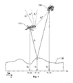
- Figure 1 illustrates both a known navigation method and the navigation method according to the invention.
- a craft 110 equipped with a GNSS receiver may determine its position x 0 , y 0 and h 0 by receiving signals from at least four different navigation satellites in the GNSS. For reasons of a simple presentation, the figure 1 only shows one of these satellites 120. Based on the received satellite signals, the GNSS receiver determines a respective distance d 0 A , d 0 B , d 0 C and d 0 D to each satellite.
- one or more of the required satellite signals may be prevented from reaching the GNSS receiver in the craft 110. In that case, the craft's 110 position cannot be determined exclusively by means of a standard GNSS receiver.
- an earth-reflected satellite signal S Dr from the navigation satellite 120 is used.
- the signal S Dr has not traveled a shortest (line-of-sight) distance d 0 A between the satellite 120 and the craft 110. Instead, the signal S Dr has bounced once against the earth surface 130. Nevertheless, it is presumed that the received signal S Dr has traveled a shortest possible reflection distance d 1 from the satellite 120 to the craft 110.
- a standard GNSS receiver is typically designed to detect the first received signal in order to suppress any multipath signals.
- the satellite's 120 position x 2 , y 2 , h 2 is known, and this information is forwarded to the navigation arrangement in the craft 110 via the signal S Dr .
- the position information x 2 , y 2 , h 2 may be forwarded to the craft 110 via a direct signal (line-of-sight) from the satellite 120. It is advantageous to receive both a direct signal and an earth-reflected signal from one and the same satellite, because thereby, by subtracting the direct signal from the earth-reflected signal, it is possible to eliminate the effects of any synchronization error between the clock signal in the satellite 120 and the local clock signal in the navigation arrangement. This, in turn, makes it possible to avoid a systematic altitude error in the calculations.
- a measured estimate d and 1 of the shortest reflection distance between the satellite 120 and the craft 110 may be derived from the earth-reflected satellite signal S Dr .
- the distribution f e1 (•) may either be assigned theoretically, or it may be determined via measurements.
- the distribution f e1 (•) may be Gaussian, however it may equally well have a different distribution.
- the measurement error e 1 includes at least two separate components, of which a first represents a measurement noise (i.e. distortions of the signals, e.g. caused by the properties of the atmosphere and the earth surface), and a second represents the fact that it may not actually be the signal which has traveled the shortest distance that is received (e.g. because this particular ray has been attenuated too much before reaching the craft 110).
- the parameters x 2 , y 2 and h 2 are known from the signal S Dr (and/or a direct signal from the satellite 120).
- a database in the proposed arrangement contains surface information pertaining to the elevation of the earth surface 130 in relation to the mean sea level z 0 at a large number of geographical positions, for instance, separated 50 meters from one another.
- the parameters x 1 , y 1 and h 1 may be derived.
- h 1 is described by a non-linear function of the x 1 and y 1 and is given by the stored terrain data.
- the parameters x 0 , y 0 and h 0 represent information, which reflects the current geographical space coordinates of the craft 110.
- the coordinates x 0 , y 0 , h 0 may be derived by registering a relative spatial movement since a previous evaluation was performed. This procedure will be discussed below with reference to the figure 2, which shows a craft 110 being located at two different positions.
- the craft 110 At a first point in time t a , the craft 110 is located at a first position x 0 , y 0 , h 0 .
- a signal from a navigation satellite 120 travels a shortest reflected distance d 1 (t a ) to the craft 110.
- the craft 110 At a second and somewhat later point in time t b , the craft 110 is located at a second position, and a shortest reflected distance between the satellite 120 and the craft 110 is instead given by d 1 (t b ).
- An inertial measurement unit in the craft 110 has registered that at the second point in time t b , the craft 110 has moved a distance in space which is represented by a set of relative coordinates ⁇ x, ⁇ y and ⁇ h respectively since a previous positioning determination was made at the first point in time t a .
- ⁇ x, ⁇ y and ⁇ h respectively since a previous positioning determination was made at the first point in time t a .
- the craft 110 is located at an estimated position x 0 + ⁇ x, y 0 + ⁇ y, h 0 + ⁇ h.
- the craft may well be located at a different location, particularly if the time difference between t b and t a is relatively large.
- an estimate of the distance d 1 not only in x 0 + ⁇ x, y 0 + ⁇ y, h 0 + ⁇ h, however also in a number of tentative points in proximity thereto.
- a volume x 0 ', y 0 ', h 0 ' for instance a sphere or a cube, is illustrated.
- a plurality of such tentative geographical positions may be selected from this volume x 0 ', y 0 ', h 0 ', which may or may not, have its center at x 0 + ⁇ x, y 0 + ⁇ y, h 0 + ⁇ h.
- Specific tentative points within the volume x 0 ', y 0 ', h 0 ' may be selected for calculation of a respective probability p(x 0 ', y 0 ', h 0 ') for each point by applying well-known probability based estimation theory, e.g. particle filters, and assuming that the probability distribution is described by a conditional probability function based on Bayes theorem. Further details regarding the principles behind this selection of points can be found in the article Nereg ⁇ rd F. et al, "A Real Time, High Integrity, Terrain Navigation System", Svenska Navigeringsdagarna, 24-25 April 2002, Sweden.
- a corresponding probability is calculated that the craft 110 is located in this point. Any probability equal to, or below, a threshold value is disregarded. Thus, the calculations must at least be repeated until one point is found which results in a probability above this threshold value. Naturally, the calculations may also be continued with respect to two or more points being associated with probabilities above the threshold value until a sufficiently high probability is attained that the craft 110 is located at a particular position. Finally, this position is regarded as the craft's 110 "true" geographical coordinates at the second point in time t b .
- FIG. 3 shows a block diagram over a proposed passive terrain navigation arrangement 300.
- the arrangement 300 includes a radio receiver system 310, an inertial measurement unit 320, a terrain database 330 and a processing unit 340.
- the radio receiver system 310 is adapted to receive an earth-reflected satellite signal S Dr from at least one navigation satellite, such as 120 in figure 2. Based on the signal S Dr the radio receiver system 310 derives a measured estimate d 1 of a shortest reflection distance to each of the at least one navigation satellite.
- the inertial measurement unit 320 is adapted to register a relative spatial movement ⁇ x, ⁇ y, ⁇ h of the arrangement 300.
- the unit 320 may contain inertial sensors in the form of gyros and accelerometers, which in turn generate one or more signals reflecting the relative spatial movement ⁇ x, ⁇ y, ⁇ h.
- the terrain database 330 contains surface information ⁇ hxy pertaining to elevations h 1 of the earth surface in relation to the mean sea level at given geographical positions x 1 , y 1 .
- these geographical positions x 1 , y 1 may represented by a box junction pattern of samples at 50 meters separation from one another.
- any alternative sample pattern and separation distance is equally well conceivable.
- the processing unit 340 receives the signal(s) reflecting the relative spatial movement information ⁇ x, ⁇ y, ⁇ h from the inertial measurement unit 320.
- the processing unit 340 also retrieves surface information ⁇ hxy from the terrain database 330.
- the processing unit 340 derives a calculated estimate d 1 of the shortest reflection distance to the satellite from which the signal S Dr is received.
- the processing unit 340 also determines a geographical position h 0 , x 0 , y 0 , based on the measured estimate d and 1 and the calculated estimate d 1 of the shortest reflection distance according to the procedure described above.
- the processing unit 340 is preferably adapted to determine the geographical position h 0 , x 0 , y 0 on basis of a probability distribution, which describes the probability that the arrangement 300 is located at a specific geographical position h 0 , x 0 , y 0 provided that a particular measured estimate d and 1 respective a particular calculated estimate d 1 of the shortest reflection distance has been derived.
- the arrangement 300 includes a barometer-based altimeter, which is adapted to register an altitude measure h 0 in relation to the mean sea level z 0 . Namely, thereby the inertial measurement unit 320 may calibrate its measurements of the relative altitude movement ⁇ h based on the altitude measure h 0 .
- a first step 410 registers a relative spatial movement.
- a step 420 receives an earth-reflected satellite signal from at least one navigation satellite, for example as illustrated by means of the signal S Dr from the satellite 120 in the figure 2.
- a step 430 then derives a measured estimate of a shortest reflection distance to the at least one navigation satellite from the received signal.
- a step 440 retrieves surface information pertaining to an elevation of the earth surface in relation to the mean sea level at at least one geographical position in proximity to a position given by a previously derived position and the registered relative spatial movement.
- a step 450 derives at least one corresponding calculated estimate of the shortest reflection distance to the at least one navigation satellite based on the relative spatial movement and the surface information.
- a step 460 determines an updated geographical position based on the measured estimate and the at least one calculated estimate of the shortest reflection distance to the at least one navigation satellite.
- steps 450 and 460 are repeated (illustrated by means of dashed arrows) until a position estimate has been determined, which has a sufficiently high probability of being correct.
- All of the process steps, as well as any sub-sequence of steps, described with reference to the figure 4 above may be controlled by means of a programmed computer apparatus, preferably located in the proposed terrain navigation arrangement.
- a programmed computer apparatus preferably located in the proposed terrain navigation arrangement.
- the embodiments of the invention described above with reference to the drawings comprise computer apparatus and processes performed in computer apparatus, the invention thus also extends to computer programs, particularly computer programs on or in a carrier, adapted for putting the invention into practice.
- the program may be in the form of source code, object code, a code intermediate source and object code such as in partially compiled form, or in any other form suitable for use in the implementation of the process according to the invention.
- the carrier may be any entity or device capable of carrying the program.
- the carrier may comprise a storage medium, such as a ROM (Read Only Memory), for example a CD (Compact Disc) or a semiconductor ROM, or a magnetic recording medium, for example a floppy disc or hard disc.
- the carrier may be a transmissible carrier such as an electrical or optical signal which may be conveyed via electrical or optical cable or by radio or by other means.
- the carrier may be constituted by such cable or device or means.
- the carrier may be an integrated circuit in which the program is embedded, the integrated circuit being adapted for performing, or for use in the performance of, the relevant processes.
Landscapes
- Engineering & Computer Science (AREA)
- Radar, Positioning & Navigation (AREA)
- Remote Sensing (AREA)
- Physics & Mathematics (AREA)
- General Physics & Mathematics (AREA)
- Aviation & Aerospace Engineering (AREA)
- Electromagnetism (AREA)
- Computer Networks & Wireless Communication (AREA)
- Automation & Control Theory (AREA)
- Position Fixing By Use Of Radio Waves (AREA)
- Harvester Elements (AREA)
Abstract
Description
- The present invention relates generally to terrain navigation based on a passive signal reception. More particularly the invention relates to a non signal-emitting terrain navigation arrangement according to claim 1 and a terrain navigation method according to claim 5. The invention also relates to a computer program according to claim 8 and a computer readable medium according to claim 9.
- In the last decades, navigation systems have been developed which facilitate the determination of a position dramatically compared to the earlier known methods. These navigation systems determine positions on basis of accurate radio signals received from a plurality of satellites (at least four), and are commonly referred to as global navigation satellite systems (GNSS:s). There exist several GNSS standards of which the most important examples are GPS (Global Positioning System, run by the U.S. Government), GLONASS (Global Navigation Satellite System, run by the Russian Federation Ministry of Defense) and the Galileo system (the European programme for global navigation services, which offers EGNOS (the European Geostationary Navigation Overlay Service), developed by a collaboration between the European Space Agency and the European Union).
- Although the above-mentioned GNSS:s generally provide relatively accurate position information, GNSS-based navigation may become problematic if, for some reason, radio signals cannot be received from a sufficiently large number of satellites during an extended time, say 10 seconds or more. For example, such radio signal outage may occur if the line of sight vectors from the receiver to one or more of the satellites to which the receiver currently is locked are covered by obstacles. The radio signals from the satellites may also be jammed (intentionally or unintentionally) or be spoofed. Therefore, at least in military applications, it is often desirable to integrate the GNSS receiver with an INS (Inertial Measurement System) and a terrain navigation system, such that the systems may aid and support one another. In fact, a GNSS receiver and an INS complement each other quite well due to their fundamental differences.
- A GNSS receiver and an INS measure different quantities. Accelerometers, found in inertial sensors, measure specific forces which are translated to a known coordinate frame with the aid of rate gyro derived measurements. Newton's laws of motion are then applied to provide velocity and position information. A GNSS is a radio navigation system. Hence, the GNSS receiver measures satellites-to-user ranges, and from these measurements, a user position and velocity can be derived. Furthermore, GNSS measurements have a long-term stability, however a noisy behavior. INS measurements on the other hand, are only short term stable; but are less noisy than GNSS receivers. Moreover, as mentioned above, since all GNSS:s are radio navigation systems, they are sensitive to external radio frequency disturbances; while an INS is not, since it is an autonomous system. Thus, an integration of a GNSS and an INS promises to combine the best of both worlds.
- In terrain navigation, the position is estimated using a terrain database and a sensor for measuring the distance from a craft to the ground together with a sensor for measuring the craft's relative movement. In similarity with GNSS measurements, a terrain navigation system is long-term stabile, however relatively noisy.
- Various solutions for combining a GNSS receiver with an INS are already known, for instance through the U.S. patent No. 6,449,559. This document describes a fully coupled positioning solution, wherein INS data is integrated with GPS data by means of a Kalman filter. Thereby, a positioning accuracy may be achieved, which is better than what would be possible to attain with a GPS receiver only.
- In contrast, the U.S. patent No. 6,256,559 describes a purely GPS-based solution for determining a craft's altitude above the ground wherein both a direct signal and an earth-reflected signal from a satellite are measured. Thereby, a reliable passive altimeter is accomplished. However, only altitude measurements are discussed, not positioning.
- Hence, the prior art both includes navigation solutions where a GNSS receiver and an INS are combined, and an altimeter solution where earth-reflected satellite signals are registered. However, there is yet no strictly passive navigation solution, which generates reliable position data also under conditions when signals from very few (i.e. less than four) satellites are available.
- The object of the present invention is therefore to provide a passive navigation solution, which alleviates the problem above and thus offers highly reliable position data on basis of external signals from as few satellites as one.
- According to one aspect of the invention the object is achieved by a passive terrain navigation arrangement, which includes a radio receiver system, an inertial measurement unit, a terrain database and a processing unit. The radio receiver system is adapted to receive an earth-reflected satellite signal from at least one reference signal source whose position is known, for instance a navigation satellite, an aircraft or a radio basestation. Based on this signal, the radio receiver system derives a measured estimate of a shortest reflection distance to the satellite. The inertial measurement unit is adapted to register a relative spatial movement of the arrangement, and produce at least one signal which reflects this movement. The terrain database contains surface information pertaining to elevations of the earth surface in relation to the mean sea level at given geographical positions. The processing unit is adapted to receive the at least one signal, which reflects the relative spatial movement. The processing unit is also adapted to retrieve surface information from the terrain database. Based on this information and the movement information signal, the processing unit derives at least one calculated estimate of the shortest reflection distance to the at least one reference signal source. The processing unit is further adapted to determine a geographical position on basis of the measured and calculated estimates of the shortest reflection distance. Preferably, a plurality of estimates is calculated, and iteratively, for each estimate a corresponding positioning is performed.
- An important advantage attained thereby is that both a relatively high accuracy and a good reliability are accomplished. At the same time, the navigation arrangement is completely silent, i.e. the arrangement does not emit any signals which may reveal it. Therefore, the arrangement is well suited for military applications where, in general, a stealthy operation is desirable.
- According to a preferred embodiment of this aspect of the invention, the processing unit is adapted to determine the geographical position on basis of a probability distribution. This distribution describes a probability that the arrangement is located at a specific geographical position provided that a particular measured estimate respective a particular calculated estimate of the shortest reflection distance is derived. Thus, a probabilistic description of the relationship between positions and reflection distances enables the position to be determined. The probabilistic description, in turn, is given by an error function, which expresses the measurement error when deriving the measured estimate of the shortest reflection distance to the satellite (i.e. the distance measure being based on the signal which is received in the radio receiver system). Hence, the probability distribution may either be theoretically assigned or be determined through measurements, and there are no limitations with respect to the statistical model. This vouches both for a high flexibility and a high accuracy.
- According to another preferred embodiment of this aspect of the invention, the terrain navigation arrangement includes a barometer-based altimeter, which is adapted to register an altitude measure in relation to the mean sea level. The inertial measurement unit is adapted to receive the altitude measure, and based thereon, calibrate its measurements of the relative altitude movement. Thereby, the relative measurements may be calibrated repetitively without signals from any additional satellites being required. Naturally, this is a desirable feature.
- According to another aspect of the invention, the object is achieved by a passive navigation method, which includes the steps of: registering a relative spatial movement; receiving an earth-reflected satellite signal from at least one reference signal source; deriving a measured estimate of a shortest reflection distance to the at least one reference signal source based on the received earth-reflected satellite signal; retrieving surface information pertaining to an elevation of the earth surface in relation to the mean sea level at at least one geographical position; deriving at least one calculated estimate of the shortest reflection distance to the at least one reference signal source based on the relative spatial movement and the surface information; and determining a geographical position based on the measured estimate and the at least one calculated estimate of the shortest reflection distance.
- Preferably, the geographical position is determined on basis of a probability distribution, which describes the probability that the arrangement is located at a specific geographical position provided that a particular measured estimate respective a particular calculated estimate of the shortest reflection distance is derived. Moreover, it is preferable to derive the at least one calculated estimate of the shortest reflection distance with respect to at least two tentative geographical positions. A probability is then calculated that the earth-reflected satellite signal was measured at each of said tentative geographical positions. Finally, the geographical position is determined based on a calculated estimate of the shortest reflection distance which is associated with a probability that exceeds a threshold value. A good accuracy may thereby be accomplished.
- The advantages of this method are apparent from the discussion hereinabove with reference to the proposed arrangement.
- According to a further aspect of the invention the object is achieved by a computer program directly loadable into the internal memory of a computer, comprising software for performing the above proposed method when said program is run on a computer.
- According to another aspect of the invention the object is achieved by a computer readable medium, having a program recorded thereon, where the program is to make a computer perform the above-proposed method.
- Thereby, the invention offers an excellent navigation tool for critical applications wherein a high accuracy and a high reliability is desired, and at the same time, any signal emission should be minimized.
- Further advantages, advantageous features and applications of the present invention will be apparent from the following description and the dependent claims.
- The present invention is now to be explained more closely by means of preferred embodiments, which are disclosed as examples, and with reference to the attached drawings.
- Figure 1
- illustrates the differences between determining the position of a craft by means of a prior-art GNSS receiver and by means of the proposed terrain navigation arrangement,
- Figure 2
- further illustrates the navigation method according to the invention,
- Figure 3
- shows a block diagram over a passive terrain navigation arrangement according to an embodiment of the invention, and
- Figure 4
- illustrates, by means of a flow diagram, a general method of navigating according to the invention.
- Figure 1 illustrates both a known navigation method and the navigation method according to the invention. Traditionally, a
craft 110 equipped with a GNSS receiver may determine its position x0, y0 and h0 by receiving signals from at least four different navigation satellites in the GNSS. For reasons of a simple presentation, the figure 1 only shows one of thesesatellites 120. Based on the received satellite signals, the GNSS receiver determines a respective distance d0 A, d0 B, d0 C and d0 D to each satellite. On further basis of these distances d0 A, d0 B, d0 C, d0 D and a timing reference, it is then possible to determine the receiver's position by means of triangulation. Namely, the position of each satellite is known and indicated to the GNSS receiver via the respective signals along with a clock signal. - As mentioned above, one or more of the required satellite signals may be prevented from reaching the GNSS receiver in the
craft 110. In that case, the craft's 110 position cannot be determined exclusively by means of a standard GNSS receiver. - However, according to the invention, an earth-reflected satellite signal SDr from the
navigation satellite 120 is used. Thus, the signal SDr has not traveled a shortest (line-of-sight) distance d0 A between thesatellite 120 and thecraft 110. Instead, the signal SDr has bounced once against theearth surface 130. Nevertheless, it is presumed that the received signal SDr has traveled a shortest possible reflection distance d1 from thesatellite 120 to thecraft 110. This is a rational assumption, since a standard GNSS receiver is typically designed to detect the first received signal in order to suppress any multipath signals. Hence, by locating the antenna of a standard GNSS receiver on a side of thecraft 110 which faces towards the general direction of theearth surface 130 an appropriate means is accomplished for receiving the earth-reflected satellite signal SDr, which has traveled a shortest reflection distance from the satellite to thecraft 110. - As also mentioned earlier, the satellite's 120 position x2, y2, h2 is known, and this information is forwarded to the navigation arrangement in the
craft 110 via the signal SDr. Alternatively, or as a complement, the position information x2, y2, h2 may be forwarded to thecraft 110 via a direct signal (line-of-sight) from thesatellite 120. It is advantageous to receive both a direct signal and an earth-reflected signal from one and the same satellite, because thereby, by subtracting the direct signal from the earth-reflected signal, it is possible to eliminate the effects of any synchronization error between the clock signal in thesatellite 120 and the local clock signal in the navigation arrangement. This, in turn, makes it possible to avoid a systematic altitude error in the calculations. - Moreover, a measured estimate d and1 of the shortest reflection distance between the
satellite 120 and thecraft 110 may be derived from the earth-reflected satellite signal SDr. The measured estimate d and1 can be expressed as: - where d1 represents an actual shortest possible reflected
distance between the
satellite 120 and thecraft 110, and - e1 represents a measurement error which has a distribution fe1(•).
-
- The distribution fe1(•) may either be assigned theoretically, or it may be determined via measurements. The distribution fe1(•) may be Gaussian, however it may equally well have a different distribution. The measurement error e1 includes at least two separate components, of which a first represents a measurement noise (i.e. distortions of the signals, e.g. caused by the properties of the atmosphere and the earth surface), and a second represents the fact that it may not actually be the signal which has traveled the shortest distance that is received (e.g. because this particular ray has been attenuated too much before reaching the craft 110).
- In any case, the actual shortest possible reflected distance d1 between the
satellite 120 and thecraft 110 is given by a distance expression:where
- x0 and y0 denote the geographical coordinates of the
craft 110, - h0 represents the craft's 110 altitude above the mean sea level z0,
- x1 and y1 denote the geographical coordinates of a
reflection point where the signal SDr bounces against the
earth surface 130 to travel a shortest reflected distance d1 to thecraft 110, - h1 is the earth surface's 130 elevation above the mean sea level z0 at the reflection point x1, y1,
- x2 and y2 denote the geographical coordinates of the
satellite 120, and - h2 represents the satellite's 120 altitude above the mean sea level z0.
-
- The parameters x2, y2 and h2 are known from the signal SDr (and/or a direct signal from the satellite 120). A database in the proposed arrangement contains surface information pertaining to the elevation of the
earth surface 130 in relation to the mean sea level z0 at a large number of geographical positions, for instance, separated 50 meters from one another. Based on the stored surface information, the parameters x1, y1 and h1 may be derived. In other words, h1 is described by a non-linear function of the x1 and y1 and is given by the stored terrain data. The parameters x0, y0 and h0 represent information, which reflects the current geographical space coordinates of thecraft 110. - Now, let us regard the positioning problem from another point-of-view. Namely, assume that we do not know the geographical space coordinates x0, y0 and h0 of the
craft 110, and further assume that we have a measured estimate d and1 of the shortest reflection distance between thesatellite 120 and the craft 110 (which is given by the received signal SDr). Instead, we now want to calculate a probability p(x0, y0, h0) that thecraft 110 is located at a specific geographical position x0, y0, h0. This may be performed by studying the expression:craft 110 being located at two different positions. At a first point in time ta, thecraft 110 is located at a first position x0, y0, h0. Here, a signal from anavigation satellite 120 travels a shortest reflected distance d1(ta) to thecraft 110. At a second and somewhat later point in time tb, thecraft 110 is located at a second position, and a shortest reflected distance between thesatellite 120 and thecraft 110 is instead given by d1(tb). - An inertial measurement unit in the
craft 110 has registered that at the second point in time tb, thecraft 110 has moved a distance in space which is represented by a set of relative coordinates Δx, Δy and Δh respectively since a previous positioning determination was made at the first point in time ta. Thus, at tb it is reasonable to assume (at least provisionally) that thecraft 110 is located at an estimated position x0+Δx, y0+Δy, h0+Δh. However, due to imperfections in the inertial measurement unit the craft may well be located at a different location, particularly if the time difference between tb and ta is relatively large. - Therefore, it is preferable to derive an estimate of the distance d1 not only in x0+Δx, y0+Δy, h0+Δh, however also in a number of tentative points in proximity thereto. In the figure 2, a volume x0', y0', h0', for instance a sphere or a cube, is illustrated. A plurality of such tentative geographical positions may be selected from this volume x0', y0', h0', which may or may not, have its center at x0+Δx, y0+Δy, h0+Δh. Specific tentative points within the volume x0', y0', h0' may be selected for calculation of a respective probability p(x0', y0', h0') for each point by applying well-known probability based estimation theory, e.g. particle filters, and assuming that the probability distribution is described by a conditional probability function based on Bayes theorem. Further details regarding the principles behind this selection of points can be found in the article Neregård F. et al, "A Real Time, High Integrity, Terrain Navigation System", Svenska Navigeringsdagarna, 24-25 April 2002, Stockholm.
- For each selected tentative point within the volume x0', y0', h0' a corresponding probability is calculated that the
craft 110 is located in this point. Any probability equal to, or below, a threshold value is disregarded. Thus, the calculations must at least be repeated until one point is found which results in a probability above this threshold value. Naturally, the calculations may also be continued with respect to two or more points being associated with probabilities above the threshold value until a sufficiently high probability is attained that thecraft 110 is located at a particular position. Finally, this position is regarded as the craft's 110 "true" geographical coordinates at the second point in time tb. - Figure 3 shows a block diagram over a proposed passive
terrain navigation arrangement 300. Thearrangement 300 includes aradio receiver system 310, aninertial measurement unit 320, aterrain database 330 and aprocessing unit 340. Theradio receiver system 310 is adapted to receive an earth-reflected satellite signal SDr from at least one navigation satellite, such as 120 in figure 2. Based on the signal SDr theradio receiver system 310 derives a measured estimate d1 of a shortest reflection distance to each of the at least one navigation satellite. Theinertial measurement unit 320 is adapted to register a relative spatial movement Δx, Δy, Δh of thearrangement 300. This means that theunit 320 may contain inertial sensors in the form of gyros and accelerometers, which in turn generate one or more signals reflecting the relative spatial movement Δx, Δy, Δh. Theterrain database 330 contains surface information Σhxy pertaining to elevations h1 of the earth surface in relation to the mean sea level at given geographical positions x1, y1. As already mentioned, these geographical positions x1, y1 may represented by a box junction pattern of samples at 50 meters separation from one another. However, of course, any alternative sample pattern and separation distance is equally well conceivable. - The
processing unit 340 receives the signal(s) reflecting the relative spatial movement information Δx, Δy, Δh from theinertial measurement unit 320. Theprocessing unit 340 also retrieves surface information Σhxy from theterrain database 330. On basis of the information Δx, Δy, Δh and Σhxy theprocessing unit 340 derives a calculated estimate d1 of the shortest reflection distance to the satellite from which the signal SDr is received. Theprocessing unit 340 also determines a geographical position h0, x0, y0, based on the measured estimate d and1 and the calculated estimate d1 of the shortest reflection distance according to the procedure described above. Thus, theprocessing unit 340 is preferably adapted to determine the geographical position h0, x0, y0 on basis of a probability distribution, which describes the probability that thearrangement 300 is located at a specific geographical position h0, x0, y0 provided that a particular measured estimate d and1 respective a particular calculated estimate d1 of the shortest reflection distance has been derived. - In addition to the above, it is preferable if the
arrangement 300 includes a barometer-based altimeter, which is adapted to register an altitude measure h0 in relation to the mean sea level z0. Namely, thereby theinertial measurement unit 320 may calibrate its measurements of the relative altitude movement Δh based on the altitude measure h0. - In order to sum up, the general method of navigating according to the invention will now be described with reference to the flow diagram in figure 4.
- A
first step 410 registers a relative spatial movement. Subsequently (or in parallel therewith), astep 420 receives an earth-reflected satellite signal from at least one navigation satellite, for example as illustrated by means of the signal SDr from thesatellite 120 in the figure 2. Astep 430 then derives a measured estimate of a shortest reflection distance to the at least one navigation satellite from the received signal. After that, astep 440 retrieves surface information pertaining to an elevation of the earth surface in relation to the mean sea level at at least one geographical position in proximity to a position given by a previously derived position and the registered relative spatial movement. Then, astep 450 derives at least one corresponding calculated estimate of the shortest reflection distance to the at least one navigation satellite based on the relative spatial movement and the surface information. Finally, astep 460 determines an updated geographical position based on the measured estimate and the at least one calculated estimate of the shortest reflection distance to the at least one navigation satellite. - In order to improve the positioning precision it is preferable to repeat the
steps steps - All of the process steps, as well as any sub-sequence of steps, described with reference to the figure 4 above may be controlled by means of a programmed computer apparatus, preferably located in the proposed terrain navigation arrangement. Moreover, although the embodiments of the invention described above with reference to the drawings comprise computer apparatus and processes performed in computer apparatus, the invention thus also extends to computer programs, particularly computer programs on or in a carrier, adapted for putting the invention into practice. The program may be in the form of source code, object code, a code intermediate source and object code such as in partially compiled form, or in any other form suitable for use in the implementation of the process according to the invention. The carrier may be any entity or device capable of carrying the program. For example, the carrier may comprise a storage medium, such as a ROM (Read Only Memory), for example a CD (Compact Disc) or a semiconductor ROM, or a magnetic recording medium, for example a floppy disc or hard disc. Further, the carrier may be a transmissible carrier such as an electrical or optical signal which may be conveyed via electrical or optical cable or by radio or by other means. When the program is embodied in a signal which may be conveyed directly by a cable or other device or means, the carrier may be constituted by such cable or device or means. Alternatively, the carrier may be an integrated circuit in which the program is embedded, the integrated circuit being adapted for performing, or for use in the performance of, the relevant processes.
- The term "comprises/comprising" when used in this specification is taken to specify the presence of stated features, integers, steps or components. However, the term does not preclude the presence or addition of one or more additional features, integers, steps or components or groups thereof.
- The invention is not restricted to the described embodiments in the figures, but may be varied freely within the scope of the claims.
Claims (10)
- A passive terrain navigation arrangement (300) comprising:a radio receiver system (310) adapted to receive an earth-reflected satellite signal (SDr) from at least one reference signal source (120) whose position is known, and based thereon, derive a measured estimate (d and1) of a shortest reflection distance to the at least one reference signal source (120),an inertial measurement unit (320) adapted to register a relative spatial movement (Δx, Δy, Δh) of the arrangement (300),a terrain database (330) containing surface information (Σhxy) pertaining to elevations (h1) of the earth surface (130) in relation to the mean sea level (z0) at given geographical positions (x1, y1), anda processing unit (340) adapted to receive at least one signal representing the relative spatial movement (Δx, Δy, Δh), retrieve surface information (Σhxy) from the terrain database (330), and based thereon, derive at least one calculated estimate (d1) of the shortest reflection distance to the at least one reference signal source (120), the processing unit (340) being further adapted to determine a geographical position (x0, y0, h0) on basis of the measured estimate (d and1) and the at least one calculated estimate (d1).
- A passive terrain navigation arrangement (300) according to claim 1, characterized in that the processing unit (340) is adapted to determine the geographical position (x0, y0, h0) on basis of a probability distribution which describes a probability that the arrangement (300) is located at a specific geographical position (x0, y0, h0) provided that a particular measured estimate (d and1) respective a particular calculated estimate (d1) of the shortest reflection distance is derived.
- A passive terrain navigation arrangement (300) according to claim 2, characterized in that the probability distribution is a conditional probability function.
- A passive terrain navigation arrangement (300) according to any one of the preceding claims, characterized in that it comprises a barometer-based altimeter adapted to register an altitude measure (h0) in relation to the mean sea level (z0), the inertial measurement unit (320) being adapted to receive the altitude measure (h0), and based thereon, calibrate its measurements of the relative spatial movement (Δx, Δy, Δh).
- A passive navigation method comprising the steps of:registering a relative spatial movement (Δx, Δy, Δh),receiving an earth-reflected satellite signal (SDr) from at least one reference signal source (120) whose position is known,deriving a measured estimate (d and1) of a shortest reflection distance to the at least one reference signal source (120) based on the received earth-reflected satellite signal (SDr),retrieving surface information (Σhxy) pertaining to an elevation (h1) of the earth surface (130) in relation to the mean sea level (z0) at at least one geographical position (x1, y1),deriving at least one calculated estimate (d1) of the shortest reflection distance to the at least one reference signal source (120) based on the relative spatial movement (Δx, Δy, Δh) and the surface information (Σhxy), anddetermining a geographical position (x0, y0, h0) based on the measured estimate (d and1) and the at least one calculated estimate (d1).
- A method according to claim 5, characterized by determining the geographical position (x0, y0, h0) on basis of a probability distribution which describes a probability that the earth-reflected satellite signal (SDr) is measured at a specific geographical position (x0, y0, h0) provided that a particular measured estimate (d and1) respective a particular calculated estimate (d1) of the shortest reflection distance is derived.
- A method according to claim 6, characterized by the steps of: deriving the at least one calculated estimate (d1) of the shortest reflection distance with respect to at least two tentative geographical positions (x0, y0, h0),
calculating a probability that the earth-reflected satellite signal (SDr) is measured at each of said tentative geographical positions (x'0, y'0, h'0), and
determining the geographical position (x0, y0, h0) based on a calculated estimate (d1) of the shortest reflection distance which is associated with a probability that exceeds a threshold value. - A method according to any one of the claims 6 or 7, characterized by the probability distribution being a Bayesian function.
- A computer program directly loadable into the internal memory of a computer, comprising software for controlling the steps of any of the claims 5 - 8 when said program is run on the computer.
- A computer readable medium, having a program recorded thereon, where the program is to make a computer control the steps of any of the claims 5 - 8.
Priority Applications (6)
| Application Number | Priority Date | Filing Date | Title |
|---|---|---|---|
| AT03018549T ATE445143T1 (en) | 2003-08-18 | 2003-08-18 | PASSIVE TERRAIN NAVIGATION |
| ES03018549T ES2331912T3 (en) | 2003-08-18 | 2003-08-18 | PASSIVE LAND NAVIGATION. |
| DE60329591T DE60329591D1 (en) | 2003-08-18 | 2003-08-18 | Passive terrain navigation |
| EP03018549A EP1508775B1 (en) | 2003-08-18 | 2003-08-18 | Passive terrain navigation |
| CA2477681A CA2477681C (en) | 2003-08-18 | 2004-08-16 | Passive terrain navigation |
| US10/919,407 US7151999B2 (en) | 2003-08-18 | 2004-08-17 | Passive terrain navigation |
Applications Claiming Priority (1)
| Application Number | Priority Date | Filing Date | Title |
|---|---|---|---|
| EP03018549A EP1508775B1 (en) | 2003-08-18 | 2003-08-18 | Passive terrain navigation |
Publications (2)
| Publication Number | Publication Date |
|---|---|
| EP1508775A1 true EP1508775A1 (en) | 2005-02-23 |
| EP1508775B1 EP1508775B1 (en) | 2009-10-07 |
Family
ID=34042852
Family Applications (1)
| Application Number | Title | Priority Date | Filing Date |
|---|---|---|---|
| EP03018549A Expired - Lifetime EP1508775B1 (en) | 2003-08-18 | 2003-08-18 | Passive terrain navigation |
Country Status (6)
| Country | Link |
|---|---|
| US (1) | US7151999B2 (en) |
| EP (1) | EP1508775B1 (en) |
| AT (1) | ATE445143T1 (en) |
| CA (1) | CA2477681C (en) |
| DE (1) | DE60329591D1 (en) |
| ES (1) | ES2331912T3 (en) |
Families Citing this family (7)
| Publication number | Priority date | Publication date | Assignee | Title |
|---|---|---|---|---|
| US20060224318A1 (en) * | 2005-03-30 | 2006-10-05 | Wilson Robert C Jr | Trajectory prediction |
| US10082583B2 (en) * | 2011-06-09 | 2018-09-25 | Invensense, Inc. | Method and apparatus for real-time positioning and navigation of a moving platform |
| US10574338B1 (en) * | 2013-02-27 | 2020-02-25 | Spatial Digital Systems, Inc. | Systems for surveillance using airborne platforms as receiving platforms for bistatic radars |
| US9541387B2 (en) | 2014-02-07 | 2017-01-10 | Goodrich Corporation | Passive altimeter |
| US10269253B2 (en) | 2015-07-16 | 2019-04-23 | Ge Aviation Systems Llc | System and method of refining trajectories for aircraft |
| CN111735437A (en) * | 2019-10-14 | 2020-10-02 | 北部湾大学 | An Interpretation Method of Submarine Geomorphology Based on Jason-1 and CryoSat-2 Satellite Data |
| US11561557B1 (en) * | 2021-07-23 | 2023-01-24 | Beta Air, Llc | System and method for initiating a command of an electric vertical take-off and landing (EVTOL) aircraft |
Citations (2)
| Publication number | Priority date | Publication date | Assignee | Title |
|---|---|---|---|---|
| US6205400B1 (en) * | 1998-11-27 | 2001-03-20 | Ching-Fang Lin | Vehicle positioning and data integrating method and system thereof |
| US6256559B1 (en) * | 2000-03-13 | 2001-07-03 | The United States Of America As Represented By The Secretary Of The Air Force | Passive altimeter employing GPS signals |
Family Cites Families (5)
| Publication number | Priority date | Publication date | Assignee | Title |
|---|---|---|---|---|
| US6246960B1 (en) * | 1998-11-06 | 2001-06-12 | Ching-Fang Lin | Enhanced integrated positioning method and system thereof for vehicle |
| US6157891A (en) * | 1998-11-16 | 2000-12-05 | Lin; Ching-Fang | Positioning and ground proximity warning method and system thereof for vehicle |
| US6449559B2 (en) * | 1998-11-20 | 2002-09-10 | American Gnc Corporation | Fully-coupled positioning process and system thereof |
| US6427122B1 (en) * | 2000-12-23 | 2002-07-30 | American Gnc Corporation | Positioning and data integrating method and system thereof |
| US6512976B1 (en) * | 2001-04-27 | 2003-01-28 | Honeywell International Inc. | Method and system for terrain aided navigation |
-
2003
- 2003-08-18 EP EP03018549A patent/EP1508775B1/en not_active Expired - Lifetime
- 2003-08-18 ES ES03018549T patent/ES2331912T3/en not_active Expired - Lifetime
- 2003-08-18 AT AT03018549T patent/ATE445143T1/en not_active IP Right Cessation
- 2003-08-18 DE DE60329591T patent/DE60329591D1/en not_active Expired - Lifetime
-
2004
- 2004-08-16 CA CA2477681A patent/CA2477681C/en not_active Expired - Fee Related
- 2004-08-17 US US10/919,407 patent/US7151999B2/en not_active Expired - Fee Related
Patent Citations (2)
| Publication number | Priority date | Publication date | Assignee | Title |
|---|---|---|---|---|
| US6205400B1 (en) * | 1998-11-27 | 2001-03-20 | Ching-Fang Lin | Vehicle positioning and data integrating method and system thereof |
| US6256559B1 (en) * | 2000-03-13 | 2001-07-03 | The United States Of America As Represented By The Secretary Of The Air Force | Passive altimeter employing GPS signals |
Non-Patent Citations (1)
| Title |
|---|
| PRITCHETT J E ET AL: "Robust guidance and navigation for airborne vehicles using GPS/terrain aiding", IEEE CONFERENCE PROCEEDINGS, 13 March 2000 (2000-03-13), pages 457 - 463, XP010376971 * |
Also Published As
| Publication number | Publication date |
|---|---|
| ES2331912T3 (en) | 2010-01-20 |
| DE60329591D1 (en) | 2009-11-19 |
| EP1508775B1 (en) | 2009-10-07 |
| US20050080562A1 (en) | 2005-04-14 |
| US7151999B2 (en) | 2006-12-19 |
| ATE445143T1 (en) | 2009-10-15 |
| CA2477681A1 (en) | 2005-02-18 |
| CA2477681C (en) | 2013-12-17 |
Similar Documents
| Publication | Publication Date | Title |
|---|---|---|
| US10175363B2 (en) | Localization and tracking using location, signal strength, and pseudorange data | |
| US20110241935A1 (en) | Method and apparatus for improving gps receiver accuracy using an embedded map database | |
| US20080238769A1 (en) | Geofencing and route adherence in global positioning system with signals from fewer than three satellites | |
| JP2010528320A (en) | Reduction of distance-dependent error in real-time kinematic (RTK) positioning | |
| JP7586885B2 (en) | Increasing sensitivity to reflected GNSS signals | |
| US10830898B2 (en) | Method and apparatus applicable to positioning in NLOS environment | |
| CN112415541A (en) | System and method for GNNS reflective surface mapping and position location estimation | |
| JP2010071686A (en) | Positioning apparatus, computer program, and positioning method | |
| KR20220039709A (en) | A method for determining a model to represent at least one environment-specific GNSS profile. | |
| EP1508775B1 (en) | Passive terrain navigation | |
| KR20110114039A (en) | DDR / GPS data fusion method | |
| JP7148039B2 (en) | Mobile object information estimation device and program | |
| JP2006162563A (en) | Data filter, data filtering method, data filtering program, positioning device, positioning method and positioning program | |
| JP5994237B2 (en) | Positioning device and program | |
| KR20230098829A (en) | At least one GNSS satellite signal evaluation method that resolves ambiguity | |
| Kirkko-Jaakkola et al. | Improving TTFF by two-satellite GNSS positioning | |
| CN118363055A (en) | A multi-source fusion positioning optimization method, device, equipment and medium | |
| KR102072630B1 (en) | Method and device based on position-domain hatch filter utilizing multi-gnss | |
| JP2009175134A (en) | Navigation system having a device for detecting inaccuracy | |
| CN117434565A (en) | A fusion positioning method and device based on multiple receiving antennas | |
| US9459344B1 (en) | Ship position and velocity using satellite ephemerides and radar range measurement of satellite | |
| JP4322829B2 (en) | Cycle slip detection device and cycle slip detection method | |
| Falletti et al. | The Kalman filter and its applications in GNSS and INS | |
| KR20180090646A (en) | Method and apparatus for location estimating using gis information | |
| US12436295B2 (en) | Method for locating a navigation unit |
Legal Events
| Date | Code | Title | Description |
|---|---|---|---|
| PUAI | Public reference made under article 153(3) epc to a published international application that has entered the european phase |
Free format text: ORIGINAL CODE: 0009012 |
|
| AK | Designated contracting states |
Kind code of ref document: A1 Designated state(s): AT BE BG CH CY CZ DE DK EE ES FI FR GB GR HU IE IT LI LU MC NL PT RO SE SI SK TR |
|
| AX | Request for extension of the european patent |
Extension state: AL LT LV MK |
|
| 17P | Request for examination filed |
Effective date: 20050322 |
|
| AKX | Designation fees paid |
Designated state(s): AT BE BG CH CY CZ DE DK EE ES FI FR GB GR HU IE IT LI LU MC NL PT RO SE SI SK TR |
|
| RIC1 | Information provided on ipc code assigned before grant |
Ipc: G01S 5/14 20060101ALI20090226BHEP Ipc: G01C 21/16 20060101ALI20090226BHEP Ipc: G01C 21/00 20060101AFI20090226BHEP Ipc: G01S 13/94 20060101ALN20090226BHEP |
|
| GRAP | Despatch of communication of intention to grant a patent |
Free format text: ORIGINAL CODE: EPIDOSNIGR1 |
|
| GRAS | Grant fee paid |
Free format text: ORIGINAL CODE: EPIDOSNIGR3 |
|
| GRAA | (expected) grant |
Free format text: ORIGINAL CODE: 0009210 |
|
| AK | Designated contracting states |
Kind code of ref document: B1 Designated state(s): AT BE BG CH CY CZ DE DK EE ES FI FR GB GR HU IE IT LI LU MC NL PT RO SE SI SK TR |
|
| REG | Reference to a national code |
Ref country code: GB Ref legal event code: FG4D |
|
| REG | Reference to a national code |
Ref country code: CH Ref legal event code: EP |
|
| REG | Reference to a national code |
Ref country code: IE Ref legal event code: FG4D |
|
| REF | Corresponds to: |
Ref document number: 60329591 Country of ref document: DE Date of ref document: 20091119 Kind code of ref document: P |
|
| REG | Reference to a national code |
Ref country code: ES Ref legal event code: FG2A Ref document number: 2331912 Country of ref document: ES Kind code of ref document: T3 |
|
| PG25 | Lapsed in a contracting state [announced via postgrant information from national office to epo] |
Ref country code: SI Free format text: LAPSE BECAUSE OF FAILURE TO SUBMIT A TRANSLATION OF THE DESCRIPTION OR TO PAY THE FEE WITHIN THE PRESCRIBED TIME-LIMIT Effective date: 20091007 |
|
| NLV1 | Nl: lapsed or annulled due to failure to fulfill the requirements of art. 29p and 29m of the patents act | ||
| PG25 | Lapsed in a contracting state [announced via postgrant information from national office to epo] |
Ref country code: PT Free format text: LAPSE BECAUSE OF FAILURE TO SUBMIT A TRANSLATION OF THE DESCRIPTION OR TO PAY THE FEE WITHIN THE PRESCRIBED TIME-LIMIT Effective date: 20100208 Ref country code: FI Free format text: LAPSE BECAUSE OF FAILURE TO SUBMIT A TRANSLATION OF THE DESCRIPTION OR TO PAY THE FEE WITHIN THE PRESCRIBED TIME-LIMIT Effective date: 20091007 Ref country code: SE Free format text: LAPSE BECAUSE OF FAILURE TO SUBMIT A TRANSLATION OF THE DESCRIPTION OR TO PAY THE FEE WITHIN THE PRESCRIBED TIME-LIMIT Effective date: 20091007 |
|
| PG25 | Lapsed in a contracting state [announced via postgrant information from national office to epo] |
Ref country code: AT Free format text: LAPSE BECAUSE OF FAILURE TO SUBMIT A TRANSLATION OF THE DESCRIPTION OR TO PAY THE FEE WITHIN THE PRESCRIBED TIME-LIMIT Effective date: 20091007 Ref country code: BE Free format text: LAPSE BECAUSE OF FAILURE TO SUBMIT A TRANSLATION OF THE DESCRIPTION OR TO PAY THE FEE WITHIN THE PRESCRIBED TIME-LIMIT Effective date: 20091007 |
|
| PG25 | Lapsed in a contracting state [announced via postgrant information from national office to epo] |
Ref country code: RO Free format text: LAPSE BECAUSE OF FAILURE TO SUBMIT A TRANSLATION OF THE DESCRIPTION OR TO PAY THE FEE WITHIN THE PRESCRIBED TIME-LIMIT Effective date: 20091007 Ref country code: DK Free format text: LAPSE BECAUSE OF FAILURE TO SUBMIT A TRANSLATION OF THE DESCRIPTION OR TO PAY THE FEE WITHIN THE PRESCRIBED TIME-LIMIT Effective date: 20091007 Ref country code: EE Free format text: LAPSE BECAUSE OF FAILURE TO SUBMIT A TRANSLATION OF THE DESCRIPTION OR TO PAY THE FEE WITHIN THE PRESCRIBED TIME-LIMIT Effective date: 20091007 Ref country code: NL Free format text: LAPSE BECAUSE OF FAILURE TO SUBMIT A TRANSLATION OF THE DESCRIPTION OR TO PAY THE FEE WITHIN THE PRESCRIBED TIME-LIMIT Effective date: 20091007 Ref country code: BG Free format text: LAPSE BECAUSE OF FAILURE TO SUBMIT A TRANSLATION OF THE DESCRIPTION OR TO PAY THE FEE WITHIN THE PRESCRIBED TIME-LIMIT Effective date: 20100107 |
|
| PLBE | No opposition filed within time limit |
Free format text: ORIGINAL CODE: 0009261 |
|
| STAA | Information on the status of an ep patent application or granted ep patent |
Free format text: STATUS: NO OPPOSITION FILED WITHIN TIME LIMIT |
|
| PG25 | Lapsed in a contracting state [announced via postgrant information from national office to epo] |
Ref country code: CZ Free format text: LAPSE BECAUSE OF FAILURE TO SUBMIT A TRANSLATION OF THE DESCRIPTION OR TO PAY THE FEE WITHIN THE PRESCRIBED TIME-LIMIT Effective date: 20091007 Ref country code: SK Free format text: LAPSE BECAUSE OF FAILURE TO SUBMIT A TRANSLATION OF THE DESCRIPTION OR TO PAY THE FEE WITHIN THE PRESCRIBED TIME-LIMIT Effective date: 20091007 |
|
| 26N | No opposition filed |
Effective date: 20100708 |
|
| PG25 | Lapsed in a contracting state [announced via postgrant information from national office to epo] |
Ref country code: GR Free format text: LAPSE BECAUSE OF FAILURE TO SUBMIT A TRANSLATION OF THE DESCRIPTION OR TO PAY THE FEE WITHIN THE PRESCRIBED TIME-LIMIT Effective date: 20100108 |
|
| PG25 | Lapsed in a contracting state [announced via postgrant information from national office to epo] |
Ref country code: MC Free format text: LAPSE BECAUSE OF NON-PAYMENT OF DUE FEES Effective date: 20100831 |
|
| REG | Reference to a national code |
Ref country code: CH Ref legal event code: PL |
|
| PG25 | Lapsed in a contracting state [announced via postgrant information from national office to epo] |
Ref country code: CH Free format text: LAPSE BECAUSE OF NON-PAYMENT OF DUE FEES Effective date: 20100831 Ref country code: LI Free format text: LAPSE BECAUSE OF NON-PAYMENT OF DUE FEES Effective date: 20100831 |
|
| PG25 | Lapsed in a contracting state [announced via postgrant information from national office to epo] |
Ref country code: IE Free format text: LAPSE BECAUSE OF NON-PAYMENT OF DUE FEES Effective date: 20100818 |
|
| PG25 | Lapsed in a contracting state [announced via postgrant information from national office to epo] |
Ref country code: CY Free format text: LAPSE BECAUSE OF FAILURE TO SUBMIT A TRANSLATION OF THE DESCRIPTION OR TO PAY THE FEE WITHIN THE PRESCRIBED TIME-LIMIT Effective date: 20091007 |
|
| PG25 | Lapsed in a contracting state [announced via postgrant information from national office to epo] |
Ref country code: HU Free format text: LAPSE BECAUSE OF FAILURE TO SUBMIT A TRANSLATION OF THE DESCRIPTION OR TO PAY THE FEE WITHIN THE PRESCRIBED TIME-LIMIT Effective date: 20100408 Ref country code: LU Free format text: LAPSE BECAUSE OF NON-PAYMENT OF DUE FEES Effective date: 20100818 |
|
| PG25 | Lapsed in a contracting state [announced via postgrant information from national office to epo] |
Ref country code: TR Free format text: LAPSE BECAUSE OF FAILURE TO SUBMIT A TRANSLATION OF THE DESCRIPTION OR TO PAY THE FEE WITHIN THE PRESCRIBED TIME-LIMIT Effective date: 20091007 |
|
| PGFP | Annual fee paid to national office [announced via postgrant information from national office to epo] |
Ref country code: DE Payment date: 20140801 Year of fee payment: 12 |
|
| PGFP | Annual fee paid to national office [announced via postgrant information from national office to epo] |
Ref country code: GB Payment date: 20140827 Year of fee payment: 12 Ref country code: ES Payment date: 20140812 Year of fee payment: 12 Ref country code: FR Payment date: 20140901 Year of fee payment: 12 |
|
| PGFP | Annual fee paid to national office [announced via postgrant information from national office to epo] |
Ref country code: IT Payment date: 20140808 Year of fee payment: 12 |
|
| REG | Reference to a national code |
Ref country code: DE Ref legal event code: R119 Ref document number: 60329591 Country of ref document: DE |
|
| GBPC | Gb: european patent ceased through non-payment of renewal fee |
Effective date: 20150818 |
|
| PG25 | Lapsed in a contracting state [announced via postgrant information from national office to epo] |
Ref country code: IT Free format text: LAPSE BECAUSE OF NON-PAYMENT OF DUE FEES Effective date: 20150818 |
|
| REG | Reference to a national code |
Ref country code: FR Ref legal event code: ST Effective date: 20160429 |
|
| PG25 | Lapsed in a contracting state [announced via postgrant information from national office to epo] |
Ref country code: DE Free format text: LAPSE BECAUSE OF NON-PAYMENT OF DUE FEES Effective date: 20160301 Ref country code: GB Free format text: LAPSE BECAUSE OF NON-PAYMENT OF DUE FEES Effective date: 20150818 |
|
| PG25 | Lapsed in a contracting state [announced via postgrant information from national office to epo] |
Ref country code: FR Free format text: LAPSE BECAUSE OF NON-PAYMENT OF DUE FEES Effective date: 20150831 |
|
| PG25 | Lapsed in a contracting state [announced via postgrant information from national office to epo] |
Ref country code: ES Free format text: LAPSE BECAUSE OF NON-PAYMENT OF DUE FEES Effective date: 20150819 |
|
| REG | Reference to a national code |
Ref country code: ES Ref legal event code: FD2A Effective date: 20180705 |